EP1516209B1 - Optical component - Google Patents
Optical component Download PDFInfo
- Publication number
- EP1516209B1 EP1516209B1 EP03736388A EP03736388A EP1516209B1 EP 1516209 B1 EP1516209 B1 EP 1516209B1 EP 03736388 A EP03736388 A EP 03736388A EP 03736388 A EP03736388 A EP 03736388A EP 1516209 B1 EP1516209 B1 EP 1516209B1
- Authority
- EP
- European Patent Office
- Prior art keywords
- electromagnetic radiation
- optical component
- portions
- radiation
- mutual
- Prior art date
- Legal status (The legal status is an assumption and is not a legal conclusion. Google has not performed a legal analysis and makes no representation as to the accuracy of the status listed.)
- Expired - Lifetime
Links
- 230000003287 optical effect Effects 0.000 title claims abstract description 103
- 230000005670 electromagnetic radiation Effects 0.000 claims abstract description 130
- 238000000034 method Methods 0.000 claims abstract description 19
- 230000005855 radiation Effects 0.000 claims description 64
- 238000002798 spectrophotometry method Methods 0.000 claims description 16
- 230000001902 propagating effect Effects 0.000 claims description 8
- WQZGKKKJIJFFOK-GASJEMHNSA-N Glucose Natural products OC[C@H]1OC(O)[C@H](O)[C@@H](O)[C@@H]1O WQZGKKKJIJFFOK-GASJEMHNSA-N 0.000 claims description 6
- 210000004369 blood Anatomy 0.000 claims description 6
- 239000008280 blood Substances 0.000 claims description 6
- 239000008103 glucose Substances 0.000 claims description 6
- 239000000126 substance Substances 0.000 claims description 5
- 210000001124 body fluid Anatomy 0.000 claims description 4
- 239000010839 body fluid Substances 0.000 claims description 4
- HVYWMOMLDIMFJA-DPAQBDIFSA-N cholesterol Chemical compound C1C=C2C[C@@H](O)CC[C@]2(C)[C@@H]2[C@@H]1[C@@H]1CC[C@H]([C@H](C)CCCC(C)C)[C@@]1(C)CC2 HVYWMOMLDIMFJA-DPAQBDIFSA-N 0.000 claims description 4
- DDRJAANPRJIHGJ-UHFFFAOYSA-N creatinine Chemical compound CN1CC(=O)NC1=N DDRJAANPRJIHGJ-UHFFFAOYSA-N 0.000 claims description 4
- 102000009027 Albumins Human genes 0.000 claims description 2
- 108010088751 Albumins Proteins 0.000 claims description 2
- 108010023302 HDL Cholesterol Proteins 0.000 claims description 2
- 102000001554 Hemoglobins Human genes 0.000 claims description 2
- 108010054147 Hemoglobins Proteins 0.000 claims description 2
- 235000012000 cholesterol Nutrition 0.000 claims description 2
- 229940109239 creatinine Drugs 0.000 claims description 2
- 238000009499 grossing Methods 0.000 claims description 2
- 210000002381 plasma Anatomy 0.000 claims description 2
- 210000002966 serum Anatomy 0.000 claims description 2
- 150000003626 triacylglycerols Chemical class 0.000 claims description 2
- 210000002700 urine Anatomy 0.000 claims description 2
- 230000003993 interaction Effects 0.000 description 10
- 239000000463 material Substances 0.000 description 7
- 238000005259 measurement Methods 0.000 description 3
- 239000000470 constituent Substances 0.000 description 2
- 206010012601 diabetes mellitus Diseases 0.000 description 2
- 230000002452 interceptive effect Effects 0.000 description 2
- 238000010521 absorption reaction Methods 0.000 description 1
- 230000003213 activating effect Effects 0.000 description 1
- 230000004913 activation Effects 0.000 description 1
- 230000001419 dependent effect Effects 0.000 description 1
- 239000011521 glass Substances 0.000 description 1
- 230000001678 irradiating effect Effects 0.000 description 1
- 239000007788 liquid Substances 0.000 description 1
- 230000003252 repetitive effect Effects 0.000 description 1
- 238000001228 spectrum Methods 0.000 description 1
Images


Classifications
-
- G—PHYSICS
- G02—OPTICS
- G02B—OPTICAL ELEMENTS, SYSTEMS OR APPARATUS
- G02B27/00—Optical systems or apparatus not provided for by any of the groups G02B1/00 - G02B26/00, G02B30/00
- G02B27/10—Beam splitting or combining systems
- G02B27/12—Beam splitting or combining systems operating by refraction only
- G02B27/126—The splitting element being a prism or prismatic array, including systems based on total internal reflection
Definitions
- the present invention relates to an optical system for spectrophotometric analysis comprising means for providing first and second electromagnetic radiation of a first and a second wavelength, respectively and a method for spectrophotometric analysis of a sample.
- Such an application may be a spectrophotometric analysis, where a sample is irradiated with the two different wavelengths and the interaction of the electromagnetic radiation and the sample is registered.
- the two different wavelengths are needed, since properties of the sample may be determined by establishing a ratio between the interactions of the sample with the different wavelengths.
- the sample is first irradiated by radiation of a first wavelength and then irradiated by radiation of a second wavelength. This may be accomplished by for example selectively activating a mirror for optionally directing the first radiation or the second radiation towards the sample to be irradiated.
- a mechanically moveable component which sets high demands on the stability of the setup and also makes the setup complex.
- the sample is irradiated by different wavelengths in different positions.
- the radiation of different wavelengths will not interact with the same parts of the sample. Therefore, differing properties of the different positions of the sample, such as differing thickness of the sample, could affect the result of the analysis.
- the sample may be irradiated by a source which emits a wide spectrum of wavelengths. However, if two specific wavelengths are needed, there may not be any source that emits these two wavelengths.
- a beam splitter may be used. Radiation incident on a beam splitter will be partly reflected and partly transmitted. Radiation of a first wavelength may then incide on one side of the beam splitter and radiation of a second wavelength may incide on the other side of the beam splitter. Part of the radiation of the first wavelength will then be transmitted through the beam splitter and will be collimated with the part of the radiation of the second wavelength that is reflected by the beam splitter. However, only 50% of the combined radiation intensity of the wavelengths may be used in the measurement, since the rest of the radiation is directed by the beam splitter away from the sample position.
- an active component may be used.
- the active component acts in a similar manner as the beam splitter. However, by applying a voltage over the active component, it may reflect 100% of the radiation incident on one side. When the voltage is turned off, the active component transmits 50% of the radiation incident on the other side.
- the active component requires an extra electric circuit for its activation. This makes the design of an optical setup using the active component more complex. Further, a measurement requires switching on and off the voltage applied to the active component.
- EP 0 390 344 and US 3,741,623 may be mentioned.
- EP 0 390 344 discloses a partially retroreflective article comprising prismatic retroreflective elements. These partially retroreflective articles are useful for internally illuminated signs and, consequently, the disclosure is not related to the field of spectrophotometric analysis.
- US 3,741,623 discloses a combined lens and reflector comprising a body of light transmitting material. An inner surface of the body is formed of a plurality of spaced cubic prisms. This disclosure relates to combined lens and reflectors, and does not relate to spectrophotometric analysis.
- the object of the invention is achieved by an optical system according to claim 1 and a method according to claim 6, wherein the inventive idea is used for spectrophotometric analysis.
- a passive optical component for directing first electromagnetic radiation incident on the component in a first direction and second electromagnetic radiation incident on the component in a second direction to a mutual direction.
- the optical component reflects essentially all the first electromagnetic radiation and transmits at least a significant portion of the second electromagnetic radiation for directing the first and the second electromagnetic radiation to a mutual direction.
- the term "passive optical component” should be interpreted as any optical component that has constant optical characteristics, i.e. the optical component should not need any outer influence in order to present its optical characteristics.
- the phrase “reflect essentially all radiation” means that most of the radiation is reflected but losses due to e.g. surface reflection or absorption may occur.
- the phrase “transmit at least a significant portion of radiation” should be interpreted as that a substantial amount of the radiation is transmitted, i.e. the portion need not be 50% but should be large enough to be clearly detectable.
- the passive optical component according to the invention allows more radiation to be directed towards a specific point than is allowed by conventional devices. Further, the passive optical component provides the funcionality through a small size component, which involves no moveable parts, and therefore is robust.
- a passive optical component comprising an interacting surface which is arranged to interact with electromagnetic radiation.
- the interacting surface has first portions, each having a surface extending in a third direction and second portions, each having a surface extending in a fourth direction.
- the first and second portions may be so arranged that essentially all radiation incident on one side of the interacting surface from the first direction and a significant portion of radiation incident on the other side of the interacting surface from the second direction will be directed by the interacting surface to a mutual direction.
- the interacting surface seen from the first direction may appear to be consisting only of the second portions. This may be accomplished by arranging the first portions such that the surfaces of the first portions extend in a direction parallel to the first direction of incident radiation. Thus, all the radiation incident from the first direction will be reflected off the surface of the second portions. Meanwhile, the interacting surface seen from the second direction may appear to consist of both the first and the second portions. Thus, the radiation incident from the second direction may be transmitted through the first portions of the interacting surface into the same direction as the reflected radiation from the first direction.
- the first portions may be arranged such that the third direction is essentially perpendicular to the mutual direction. Then, the radiation incident from the second direction may incide on the first portions with an angle of incidence of 90°. This implies that essentially all of this radiation inciding on a first portion will then be transmitted without being deflected.
- the optical component reflects the first electromagnetic radiation through internal reflection. Then, the second portions of the interacting surface of the optical component need not have a surface which is processed for optimal reflection properties. Instead, the total internal reflection which may occur when radiation passes from a thicker to a thinner medium is used. When the angle of incidence is larger than a critical angle all radiation incident on the second portions is reflected through total internal reflection.
- Radiation directed out from the optical component will form a checked pattern, since the radiation incident on the interacting surface will not impinge on a continuous surface.
- all first portions are of equal size and all second portions are of equal size. This implies that the radiation directed out from the optical component will form a uniform pattern.
- the first portions and the second portions may be of equal size. This implies that all areas of the checked pattern will be equally large. Further, half of the radiation incident from the second direction will impinge on a first portion of the interacting surface. Thus, 50% of the radiation incident from the second direction will be transmitted.
- an angle between the third and the fourth directions is essentially 45°. This implies that the radiation incident from the first direction, while being parallel to the third direction, in which the surfaces of the first portions extend, will be deflected through reflection into the same direction as the radiation incident from the second direction is transmitted in. Thus, the interacting surface seen from the first direction will appear to be consisting only of the second portions.
- the passive optical component may further comprise a plane input surface extending in a direction perpendicular to the third direction.
- the radiation incident from the first direction may impinge the input surface and be transmitted through the optical component to the interacting surface.
- the input surface extends in a direction perpendicular to the third direction
- the radiation incident from the first direction may impinge perpendicularly to this input surface while the first direction is parallel to the third direction. Then, all radiation incident from the first direction will be transmitted through the input surface without deflection.
- the passive optical component may further comprise a plane output surface extending in a direction perpendicular to the mutual direction. This implies that all the radiation propagating in the mutual direction after having interacted with the interacting surface will leave the optical component through the output surface without being deflected.
- the interacting surface may extend from a first end of the output surface to a first end of the input surface.
- a second end of the input surface may be connected to a second end of the output surface.
- the input surface, the interacting surface, and the output surface will form an essentially triangular cross-section. This implies that the optical component will have a simple shape.
- the passive optical component may be essentially formed of a plastic material.
- the optical component may easily be shaped to a desired form in a plastic material. Further, a plastic material having required optical characteristics may easily be found.
- an optical system for spectrophotometric analysis.
- the optical system comprises means for providing first and second electromagnetic radiation of a first and a second wavelength, respectively.
- the optical system further comprises a passive optical component for directing said first and said second electromagnetic radiation in a mutual direction.
- the passive optical component comprises an interacting surface which is arranged to interact with said first and second electromagnetic radiation.
- the interacting surface comprises first portions, each having a surface extending in a first direction, which is essentially perpendicular to the mutual direction, and second portions, each having a surface extending in a second direction.
- the passive optical component reflects essentially all of said first electromagnetic radiation and transmits at least a significant portion of the second electromagnetic radiation for directing the first and the second electromagnetic radiation in the mutual direction.
- a method for spectrophotometric analysis of a sample.
- the method comprises the steps of emitting first electromagnetic radiation of a first wavelength and second electromagnetic radiation of a second wavelength, directing the first electromagnetic radiation and the second electromagnetic radiation to a mutual direction by means of a passive optical component.
- the passive optical component comprises an interacting surface which is arranged to interact with said first and second electromagnetic radiation.
- the interacting surface comprises first portions, each having a surface extending in a first direction, which is essentially perpendicular to the mutual direction, and second portions, each having a surface extending in a second direction.
- the passive optical component reflects essentially all of said first electromagnetic radiation and transmits at least a significant portion of said second electromagnetic radiation for directing the first and the second electromagnetic radiation to the mutual direction.
- the method further comprises the step of detecting electromagnetic radiation propagating in the mutual direction after it has been transmitted through the sample.
- a spectrophotometric analysis using this optical system or by means of this method may utilize a large portion of the emitted electromagnetic radiation without the need for any moveable parts or any change in the optical setup during the analysis. This implies that the system is very easy to use and robust. Thus, it is suited for domestic use.
- the system and the method take advantage of the excellent optical characteristics of the passive optical component.
- the optical system may be used for irradiating a sample with the first and the second electromagnetic radiation simultaneously or separately.
- the means for providing first and second electromagnetic radiation comprises a first and a second source, which emit the first and second electromagnetic radiation, respectively.
- a first and a second source which emit the first and second electromagnetic radiation, respectively.
- the means for providing first and second electromagnetic radiation comprises a source, which emits both the first and the second electromagnetic radiation.
- the means for providing first and second electromagnetic radiation may further comprise means for splitting the electromagnetic radiation of the source into a first and a second path and filters for transmitting the first electromagnetic radiation of the first path and the second electromagnetic radiation of the second path.
- the radiation of the first and the second wavelengths may be extracted from the radiation emitted by the source and may be directed in different directions towards the passive optical component.
- the optical system may further comprise a diffusor for smoothing out the radiation intensity over a cross-section of the electromagnetic radiation propagating in the mutual direction.
- the electromagnetic radiation that leaves the passive optical component propagating in the mutual direction may not have a homogenous radiation intensity over its cross-section. It may be therefore be suitable to lead the radiation through a diffusor.
- the method for spectrophotometric analysis may be used for determining an amount of a chemical substance in a body fluid.
- the chemical substance may typically be any one of glucose, hemoglobin, albumin, creatinine, cholesterol, HDL-cholesterol, triglycerides, or CRP.
- the body fluid may be any one of blood, plasma, serum, and urine.
- the method may e.g. be used for determining glucose in a blood sample.
- the method for spectrophotometric analysis is so simple that it is suitable for domestic use. Thus, it may provide a fast method, which a diabetic may use for determining the glucose content in his/her blood.
- the optical component 2 comprises an interacting surface 4, which is intended to interact with electromagnetic radiation impinging on the optical component 2.
- the interacting surface 4 is formed according to a repetitive pattern.
- the interacting surface 4 comprises first portions 6 having a surface extending in a first direction and second portions 8 having a surface extending in a second direction.
- the interacting surface 4 is constituted of alternating first portions 6 and second portions 8. The first and the second directions form an angle of 45°.
- portions 6, 8 form a "stair-like" shape of the interacting surface 4.
- Several “stair-like” parts are formed side by side in the interacting surface 4.
- Two adjacent “stair-like” parts are displaced in depth to each other.
- third portions 10 are formed between the "stair-like” parts.
- These third portions 10 have a surface, which is perpendicular to both the surface of the first portions 6 and the surface of the second portions 8.
- the optical component 2 further comprises an input surface 12.
- This input surface 12 is perpendicular to the first portions 6.
- the optical component 2 also comprises an output surface 14, which is parallel to the first portions 6.
- the interacting surface 4 extends from a first end 16, in which it is connected to a first end 18 of the output surface 14, to a second end 20, in which it is connected to a first end 22 of the input surface 12.
- the input surface 12 is connected in a second end 24 to a second end 26 of the output surface 14.
- the input surface 12 and the output surface 14 form a right angle at their connection.
- a cross-section of the input surface 12, the output surface 14, and the interacting surface 4 form an essentially right angle triangle.
- the optical component 4 may be formed in one piece. It is formed of a material that has optical characteristics, which are suitable for the electromagnetic radiation that it is to interact with.
- the optical component 4 may be formed of a plastic material that has the required optical characteristics. However, the optical component 4 may also be formed of glass.
- the first electromagnetic radiation impinges perpendicularly on the input surface 12 of the optical component 2.
- the perpendicular incidence implies that essentially all radiation will be transmitted through the input surface 12 without being deflected.
- the first electromagnetic radiation propagates in a third direction, which is parallel to the first direction. Thus, the first electromagnetic radiation will not impinge on the first portions 6 of the interacting surface 4. All the first electromagnetic radiation propagating through the optical component 2 will interact with the second portions 8 of the optical component 2.
- the material of the optical component 2 has a refractive index that is large enough to cause total internal reflection for the first electromagnetic radiation impinging on the second portions 8.
- the interaction of the optical component 2 with second electromagnetic radiation incident from a fourth direction will be explained.
- the second electromagnetic radiation is incident on the interacting surface 4 of the optical component 2.
- the second electromagnetic radiation impinges perpendicularly on the first portions 6 of the interacting surface 4.
- the perpendicular incidence implies that essentially all radiation will be transmitted through the first portions 6 without being deflected.
- Part of the second electromagnetic radiation will impinge on the second portions 8 of the interacting surface.
- This part of the second electromagnetic radiation will be reflected or be deflectedly transmitted.
- the part of the second electromagnetic radiation which impinges on the first portions 6 will propagate after being transmitted through the surface in the same direction as the first electromagnetic radiation has after it has interacted with the second portions 8.
- the passive optical component provides a possibility of directing first electromagnetic radiation incident on the component in a first direction and second electromagnetic radiation incident on the component in a second direction to a mutual direction.
- the optical component 2 directs essentially all the first electromagnetic radiation to the mutual direction. Only the part of the second electromagnetic radiation that is incident on the first portions 6 is directed in the mutual direction. Thus, if the first portions 6 and the second portions 8 are equally large, 50% of the second electromagnetic radiation will be directed in the mutual direction.
- Both the first and the second electromagnetic radiation directed in the mutual direction will form a checkered pattern in their cross-section, the pattern corresponding to the first 6 and second portions 8. Since neither the first nor the second electromagnetic radiation is incident on a continuous surface, the radiation outputted from the interacting surface 4 will not be continuous over its cross-section. Thus, the cross-section of the first electromagnetic radiation will vary between a high intensity in areas corresponding to the interaction with the second portions 8 and no intensity at all in areas corresponding to the interaction with the first portions 6, and vice versa for the second electromagnetic radiation.
- the pattern of the cross-section is dependent on the design of the first 6 and the second portions 8.
- the optical system 30 comprises a first and a second electromagnetic radiation sources 32, 34, in the form of light emitting diodes (LEDs) emitting electromagnetic radiation of two different wavelengths.
- the first electromagnetic radiation source 32 emits first electromagnetic radiation of a first wavelength.
- the first electromagnetic radiation passes a collimator 36 and is then incident on the interactive surface 4.
- the second electromagnetic source 34 emits second electromagnetic radiation of a second wavelength.
- the second electromagnetic radiation passes a collimator 40 and is then reflected by a reflective surface 42 towards the interactive surface 4 of the optical component 2.
- the first electromagnetic radiation will interact with the optical component 2 according to the interaction described above with reference to Fig. 2 .
- the interacting surface 4 of the optical component 2 is in contact with air so that the first electromagnetic radiation will be totally reflected in the second portions of the interacting surface 4.
- the second electromagnetic radiation will interact with the optical component according to the interaction described above with reference to Fig. 3 .
- the first and the second electromagnetic radiation are directed into a mutual direction.
- the first and second electromagnetic radiation outputted from the optical component are then reflected in a reflective surface 44 towards a sample.
- the first and the second electromagnetic radiation irradiate the same portion of the sample 46.
- the optical system 30 further comprises a detector 48.
- the detector 48 detects radiation that has been transmitted through the sample 46. Since the first and the second electromagnetic radiation propagate in a mutual direction, they will interact with the same parts of the sample 46. The detected radiation is then analyzed, whereby an amount of a constituent in the sample 46 may be determined.
- the optical system 30 may comprise a diffusor (not shown) arranged in the radiation path after the optical component 2.
- the diffusor will smooth out the intensity distribution of the electromagnetic radiation.
- the checkered pattern of the electromagnetic radiation will be diffused into a more continuous pattern.
- the smooth distribution of the intensity of the electromagnetic radiation will provide a more uniform interaction between the electromagnetic radiation and the sample 46 over the cross-section of the radiation.
- a larger portion of the first electromagnetic radiation than of the second electromagnetic radiation is directed into the mutual direction by the optical component 2.
- the second source 34 emitting the second electromagnetic radiation may be stronger than the first source 32 to compensate for this.
- it may be desired that the radiation of the first wavelength has a larger intensity than the radiation of the second wavelength, e.g. if the radiation of the second wavelength is used for the purpose of calibration.
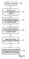
- a sample 46 that is to be analyzed is obtained, step 102, and prepared to suit the analysis.
- the sample is analyzed using the optical system 30 described above.
- first electromagnetic radiation of a first wavelength and second electromagnetic radiation of a second wavelength are emitted, step 104.
- the first electromagnetic radiation and the second electromagnetic radiation are directed to a mutual direction by means of the passive optical component, step 106.
- the first and the second electromagnetic radiation are then passed through the sample 46, step 108.
- step 110 the electromagnetic radiation that has been transmitted through the sample 46 is detected. Then, the detected amounts of radiation is analyzed and an amount of a constituent in the sample 46 is determined, step 112.
- the sample 46 may e.g. be a blood sample.
- the determined amount may be an amount of glucose in the blood.
- the optical system 30 may be so simply designed that a diabetic may use it at home for determining his or her glucose value.
- the spectrophotometric analysis may be used for determining an amount of any substance suspended in a liquid.
- the pattern formed by the first and the second portions may be varied in infinite ways. If the first portions are made larger than the second portions, a larger part of the second electromagnetic radiation will be transmitted through the interacting surface. Further, the angle between the first and the second portions may be varied. In this case, the angle of incidence of the first electromagnetic radiation will also have to be changed, so that the first electromagnetic radiation is reflected into the mutual direction. However, this implies that the first electromagnetic radiation will not propagate in parallel with the first portions. Thus, a small part of the first electromagnetic radiation will be lost through interaction with the first portions.
- the optical system may be arranged such that the electromagnetic radiation of the two sources is emitted at the same time or sequentially.
- the sources need not emit a specific, discrete wavelength, instead they may emit wavelengths of different intervals. Further, only one source may be used.
- the electromagnetic radiation is divided into two paths. In a first path, a first wavelength is passed, and in a second path a second wavelength is passed. The electromagnetic radiation of the first path and of the second path are then fed to the optical component in a similar way as the first and second electromagnetic radiation described above.
Landscapes
- Physics & Mathematics (AREA)
- General Physics & Mathematics (AREA)
- Optics & Photonics (AREA)
- Investigating Or Analysing Materials By Optical Means (AREA)
- Glass Compositions (AREA)
- Optical Couplings Of Light Guides (AREA)
Abstract
Description
- The present invention relates to an optical system for spectrophotometric analysis comprising means for providing first and second electromagnetic radiation of a first and a second wavelength, respectively and a method for spectrophotometric analysis of a sample.
- In several applications there is a need for emitting electromagnetic radiation containing two different wavelengths towards a specific point. Such an application may be a spectrophotometric analysis, where a sample is irradiated with the two different wavelengths and the interaction of the electromagnetic radiation and the sample is registered. The two different wavelengths are needed, since properties of the sample may be determined by establishing a ratio between the interactions of the sample with the different wavelengths.
- There are a number of solutions to the need for emitting electromagnetic radiation containing two wavelengths towards a sample. According to a first solution, the sample is first irradiated by radiation of a first wavelength and then irradiated by radiation of a second wavelength. This may be accomplished by for example selectively activating a mirror for optionally directing the first radiation or the second radiation towards the sample to be irradiated. However, this requires a mechanically moveable component, which sets high demands on the stability of the setup and also makes the setup complex.
- According to a second solution, the sample is irradiated by different wavelengths in different positions. However, then the radiation of different wavelengths will not interact with the same parts of the sample. Therefore, differing properties of the different positions of the sample, such as differing thickness of the sample, could affect the result of the analysis.
- According to a third solution, the sample may be irradiated by a source which emits a wide spectrum of wavelengths. However, if two specific wavelengths are needed, there may not be any source that emits these two wavelengths.
- According to a fourth solution, a beam splitter may be used. Radiation incident on a beam splitter will be partly reflected and partly transmitted. Radiation of a first wavelength may then incide on one side of the beam splitter and radiation of a second wavelength may incide on the other side of the beam splitter. Part of the radiation of the first wavelength will then be transmitted through the beam splitter and will be collimated with the part of the radiation of the second wavelength that is reflected by the beam splitter. However, only 50% of the combined radiation intensity of the wavelengths may be used in the measurement, since the rest of the radiation is directed by the beam splitter away from the sample position.
- According to a fifth solution, an active component may be used. The active component acts in a similar manner as the beam splitter. However, by applying a voltage over the active component, it may reflect 100% of the radiation incident on one side. When the voltage is turned off, the active component transmits 50% of the radiation incident on the other side. The active component requires an extra electric circuit for its activation. This makes the design of an optical setup using the active component more complex. Further, a measurement requires switching on and off the voltage applied to the active component.
- In this context,
EP 0 390 344 andUS 3,741,623 may be mentioned.EP 0 390 344 discloses a partially retroreflective article comprising prismatic retroreflective elements. These partially retroreflective articles are useful for internally illuminated signs and, consequently, the disclosure is not related to the field of spectrophotometric analysis. -
US 3,741,623 discloses a combined lens and reflector comprising a body of light transmitting material. An inner surface of the body is formed of a plurality of spaced cubic prisms. This disclosure relates to combined lens and reflectors, and does not relate to spectrophotometric analysis. - It is an object of the invention to provide an optical component, which may overcome the above-identified problems and which provides better optical characteristics for radiation from different directions without the need of any active manipulation of the optical setup.
- The object of the invention is achieved by an optical system according to claim 1 and a method according to
claim 6, wherein the inventive idea is used for spectrophotometric analysis. - According to the invention, a passive optical component is provided for directing first electromagnetic radiation incident on the component in a first direction and second electromagnetic radiation incident on the component in a second direction to a mutual direction. The optical component reflects essentially all the first electromagnetic radiation and transmits at least a significant portion of the second electromagnetic radiation for directing the first and the second electromagnetic radiation to a mutual direction.
- In the context of this application, the term "passive optical component" should be interpreted as any optical component that has constant optical characteristics, i.e. the optical component should not need any outer influence in order to present its optical characteristics. Further, as used herein the phrase "reflect essentially all radiation" means that most of the radiation is reflected but losses due to e.g. surface reflection or absorption may occur. Also, the phrase "transmit at least a significant portion of radiation" should be interpreted as that a substantial amount of the radiation is transmitted, i.e. the portion need not be 50% but should be large enough to be clearly detectable.
- The passive optical component according to the invention allows more radiation to be directed towards a specific point than is allowed by conventional devices. Further, the passive optical component provides the funcionality through a small size component, which involves no moveable parts, and therefore is robust.
- Preferably, there is provided a passive optical component comprising an interacting surface which is arranged to interact with electromagnetic radiation. The interacting surface has first portions, each having a surface extending in a third direction and second portions, each having a surface extending in a fourth direction. The first and second portions may be so arranged that essentially all radiation incident on one side of the interacting surface from the first direction and a significant portion of radiation incident on the other side of the interacting surface from the second direction will be directed by the interacting surface to a mutual direction.
- By intelligent arrangement of the first portions relative the first direction of incident radiation, the interacting surface seen from the first direction may appear to be consisting only of the second portions. This may be accomplished by arranging the first portions such that the surfaces of the first portions extend in a direction parallel to the first direction of incident radiation. Thus, all the radiation incident from the first direction will be reflected off the surface of the second portions. Meanwhile, the interacting surface seen from the second direction may appear to consist of both the first and the second portions. Thus, the radiation incident from the second direction may be transmitted through the first portions of the interacting surface into the same direction as the reflected radiation from the first direction.
- The first portions may be arranged such that the third direction is essentially perpendicular to the mutual direction. Then, the radiation incident from the second direction may incide on the first portions with an angle of incidence of 90°. This implies that essentially all of this radiation inciding on a first portion will then be transmitted without being deflected.
- According to one embodiment, the optical component reflects the first electromagnetic radiation through internal reflection. Then, the second portions of the interacting surface of the optical component need not have a surface which is processed for optimal reflection properties. Instead, the total internal reflection which may occur when radiation passes from a thicker to a thinner medium is used. When the angle of incidence is larger than a critical angle all radiation incident on the second portions is reflected through total internal reflection.
- Radiation directed out from the optical component will form a checked pattern, since the radiation incident on the interacting surface will not impinge on a continuous surface. According to one embodiment, all first portions are of equal size and all second portions are of equal size. This implies that the radiation directed out from the optical component will form a uniform pattern.
- The first portions and the second portions may be of equal size. This implies that all areas of the checked pattern will be equally large. Further, half of the radiation incident from the second direction will impinge on a first portion of the interacting surface. Thus, 50% of the radiation incident from the second direction will be transmitted.
- According to one embodiment, an angle between the third and the fourth directions is essentially 45°. This implies that the radiation incident from the first direction, while being parallel to the third direction, in which the surfaces of the first portions extend, will be deflected through reflection into the same direction as the radiation incident from the second direction is transmitted in. Thus, the interacting surface seen from the first direction will appear to be consisting only of the second portions.
- The passive optical component may further comprise a plane input surface extending in a direction perpendicular to the third direction. The radiation incident from the first direction may impinge the input surface and be transmitted through the optical component to the interacting surface. When the input surface extends in a direction perpendicular to the third direction, the radiation incident from the first direction may impinge perpendicularly to this input surface while the first direction is parallel to the third direction. Then, all radiation incident from the first direction will be transmitted through the input surface without deflection.
- The passive optical component may further comprise a plane output surface extending in a direction perpendicular to the mutual direction. This implies that all the radiation propagating in the mutual direction after having interacted with the interacting surface will leave the optical component through the output surface without being deflected.
- The interacting surface may extend from a first end of the output surface to a first end of the input surface. Thus, all radiation incident on the input surface in the first direction will impinge on the interacting surface and all radiation leaving the interacting surface in the mutual direction will leave the optical component through the output surface.
- A second end of the input surface may be connected to a second end of the output surface. Thus, the input surface, the interacting surface, and the output surface will form an essentially triangular cross-section. This implies that the optical component will have a simple shape.
- The passive optical component may be essentially formed of a plastic material. The optical component may easily be shaped to a desired form in a plastic material. Further, a plastic material having required optical characteristics may easily be found.
- According to an aspect of the invention, an optical system is provided for spectrophotometric analysis. The optical system comprises means for providing first and second electromagnetic radiation of a first and a second wavelength, respectively. The optical system further comprises a passive optical component for directing said first and said second electromagnetic radiation in a mutual direction. The passive optical component comprises an interacting surface which is arranged to interact with said first and second electromagnetic radiation. The interacting surface comprises first portions, each having a surface extending in a first direction, which is essentially perpendicular to the mutual direction, and second portions, each having a surface extending in a second direction. Thus, the passive optical component reflects essentially all of said first electromagnetic radiation and transmits at least a significant portion of the second electromagnetic radiation for directing the first and the second electromagnetic radiation in the mutual direction.
- According to another aspect of the invention, a method is provided for spectrophotometric analysis of a sample. The method comprises the steps of emitting first electromagnetic radiation of a first wavelength and second electromagnetic radiation of a second wavelength, directing the first electromagnetic radiation and the second electromagnetic radiation to a mutual direction by means of a passive optical component. The passive optical component comprises an interacting surface which is arranged to interact with said first and second electromagnetic radiation. The interacting surface comprises first portions, each having a surface extending in a first direction, which is essentially perpendicular to the mutual direction, and second portions, each having a surface extending in a second direction. Thus, the passive optical component reflects essentially all of said first electromagnetic radiation and transmits at least a significant portion of said second electromagnetic radiation for directing the first and the second electromagnetic radiation to the mutual direction. The method further comprises the step of detecting electromagnetic radiation propagating in the mutual direction after it has been transmitted through the sample.
- A spectrophotometric analysis using this optical system or by means of this method may utilize a large portion of the emitted electromagnetic radiation without the need for any moveable parts or any change in the optical setup during the analysis. This implies that the system is very easy to use and robust. Thus, it is suited for domestic use.
- The system and the method take advantage of the excellent optical characteristics of the passive optical component. The optical system may be used for irradiating a sample with the first and the second electromagnetic radiation simultaneously or separately.
- According to one embodiment, the means for providing first and second electromagnetic radiation comprises a first and a second source, which emit the first and second electromagnetic radiation, respectively. This implies that sources which are designed for emitting only the wavelengths that are needed for the spectrophotometric analysis may be used. Thus, the radiation emitted by the sources may be used efficiently.
- According to another embodiment, the means for providing first and second electromagnetic radiation comprises a source, which emits both the first and the second electromagnetic radiation.
- The means for providing first and second electromagnetic radiation may further comprise means for splitting the electromagnetic radiation of the source into a first and a second path and filters for transmitting the first electromagnetic radiation of the first path and the second electromagnetic radiation of the second path. Hereby, the radiation of the first and the second wavelengths may be extracted from the radiation emitted by the source and may be directed in different directions towards the passive optical component.
- The optical system may further comprise a diffusor for smoothing out the radiation intensity over a cross-section of the electromagnetic radiation propagating in the mutual direction. The electromagnetic radiation that leaves the passive optical component propagating in the mutual direction may not have a homogenous radiation intensity over its cross-section. It may be therefore be suitable to lead the radiation through a diffusor.
- The method for spectrophotometric analysis may be used for determining an amount of a chemical substance in a body fluid. The chemical substance may typically be any one of glucose, hemoglobin, albumin, creatinine, cholesterol, HDL-cholesterol, triglycerides, or CRP. Further, the body fluid may be any one of blood, plasma, serum, and urine. Thus, the method may e.g. be used for determining glucose in a blood sample. The method for spectrophotometric analysis is so simple that it is suitable for domestic use. Thus, it may provide a fast method, which a diabetic may use for determining the glucose content in his/her blood.
- The present invention will now be described in more detail by way of example referring to the appended drawings.
-
Fig. 1 is a perspective view of an optical component according to the invention. -
Fig. 2 is a side view of the optical component ofFig. 1 illustrating the path for radiation from a first direction. -
Fig. 3 is a side view of the optical component ofFig. 1 illustrating the path for radiation from a second direction. -
Fig. 4 is a schematic view of an optical system according to the invention. -
Fig. 5 is a flow chart illustrating a method according to the invention. - Referring to
Fig. 1 , anoptical component 2 according to the invention will be described. Theoptical component 2 comprises an interactingsurface 4, which is intended to interact with electromagnetic radiation impinging on theoptical component 2. The interactingsurface 4 is formed according to a repetitive pattern. The interactingsurface 4 comprisesfirst portions 6 having a surface extending in a first direction andsecond portions 8 having a surface extending in a second direction. The interactingsurface 4 is constituted of alternatingfirst portions 6 andsecond portions 8. The first and the second directions form an angle of 45°. - These
portions surface 4. Several "stair-like" parts are formed side by side in the interactingsurface 4. Two adjacent "stair-like" parts are displaced in depth to each other. Thus,third portions 10 are formed between the "stair-like" parts. Thesethird portions 10 have a surface, which is perpendicular to both the surface of thefirst portions 6 and the surface of thesecond portions 8. - As is best seen in
Figs 2 and3 , theoptical component 2 further comprises aninput surface 12. Thisinput surface 12 is perpendicular to thefirst portions 6. Theoptical component 2 also comprises anoutput surface 14, which is parallel to thefirst portions 6. The interactingsurface 4 extends from afirst end 16, in which it is connected to afirst end 18 of theoutput surface 14, to asecond end 20, in which it is connected to afirst end 22 of theinput surface 12. Theinput surface 12 is connected in asecond end 24 to asecond end 26 of theoutput surface 14. Theinput surface 12 and theoutput surface 14 form a right angle at their connection. A cross-section of theinput surface 12, theoutput surface 14, and the interactingsurface 4 form an essentially right angle triangle. - The
optical component 4 may be formed in one piece. It is formed of a material that has optical characteristics, which are suitable for the electromagnetic radiation that it is to interact with. Theoptical component 4 may be formed of a plastic material that has the required optical characteristics. However, theoptical component 4 may also be formed of glass. - Referring now to
Fig. 2 , the interaction of theoptical component 2 with first electromagnetic radiation incident from a third direction will be explained. The first electromagnetic radiation impinges perpendicularly on theinput surface 12 of theoptical component 2. The perpendicular incidence implies that essentially all radiation will be transmitted through theinput surface 12 without being deflected. The first electromagnetic radiation propagates in a third direction, which is parallel to the first direction. Thus, the first electromagnetic radiation will not impinge on thefirst portions 6 of the interactingsurface 4. All the first electromagnetic radiation propagating through theoptical component 2 will interact with thesecond portions 8 of theoptical component 2. Since thesesecond portions 8 are angled 45° to thefirst portions 6 and thus to the propagating direction of the first electromagnetic radiation, the first electromagnetic radiation will be deflected 90° by reflection at the second portions. The material of theoptical component 2 has a refractive index that is large enough to cause total internal reflection for the first electromagnetic radiation impinging on thesecond portions 8. - Referring to
Fig. 3 , the interaction of theoptical component 2 with second electromagnetic radiation incident from a fourth direction will be explained. The second electromagnetic radiation is incident on the interactingsurface 4 of theoptical component 2. The second electromagnetic radiation impinges perpendicularly on thefirst portions 6 of the interactingsurface 4. The perpendicular incidence implies that essentially all radiation will be transmitted through thefirst portions 6 without being deflected. Part of the second electromagnetic radiation will impinge on thesecond portions 8 of the interacting surface. This part of the second electromagnetic radiation will be reflected or be deflectedly transmitted. However, the part of the second electromagnetic radiation which impinges on thefirst portions 6 will propagate after being transmitted through the surface in the same direction as the first electromagnetic radiation has after it has interacted with thesecond portions 8. Thus, the passive optical component provides a possibility of directing first electromagnetic radiation incident on the component in a first direction and second electromagnetic radiation incident on the component in a second direction to a mutual direction. Theoptical component 2 directs essentially all the first electromagnetic radiation to the mutual direction. Only the part of the second electromagnetic radiation that is incident on thefirst portions 6 is directed in the mutual direction. Thus, if thefirst portions 6 and thesecond portions 8 are equally large, 50% of the second electromagnetic radiation will be directed in the mutual direction. - Both the first and the second electromagnetic radiation directed in the mutual direction will form a checkered pattern in their cross-section, the pattern corresponding to the first 6 and
second portions 8. Since neither the first nor the second electromagnetic radiation is incident on a continuous surface, the radiation outputted from the interactingsurface 4 will not be continuous over its cross-section. Thus, the cross-section of the first electromagnetic radiation will vary between a high intensity in areas corresponding to the interaction with thesecond portions 8 and no intensity at all in areas corresponding to the interaction with thefirst portions 6, and vice versa for the second electromagnetic radiation. The pattern of the cross-section is dependent on the design of the first 6 and thesecond portions 8. - Referring now to
Fig. 4 , anoptical system 30 using theoptical component 2 will be explained. Theoptical system 30 comprises a first and a secondelectromagnetic radiation sources electromagnetic radiation source 32 emits first electromagnetic radiation of a first wavelength. The first electromagnetic radiation passes acollimator 36 and is then incident on theinteractive surface 4. The secondelectromagnetic source 34 emits second electromagnetic radiation of a second wavelength. The second electromagnetic radiation passes acollimator 40 and is then reflected by areflective surface 42 towards theinteractive surface 4 of theoptical component 2. - The first electromagnetic radiation will interact with the
optical component 2 according to the interaction described above with reference toFig. 2 . The interactingsurface 4 of theoptical component 2 is in contact with air so that the first electromagnetic radiation will be totally reflected in the second portions of the interactingsurface 4. The second electromagnetic radiation will interact with the optical component according to the interaction described above with reference toFig. 3 . Thus, the first and the second electromagnetic radiation are directed into a mutual direction. The first and second electromagnetic radiation outputted from the optical component are then reflected in areflective surface 44 towards a sample. The first and the second electromagnetic radiation irradiate the same portion of thesample 46. - The
optical system 30 further comprises adetector 48. Thedetector 48 detects radiation that has been transmitted through thesample 46. Since the first and the second electromagnetic radiation propagate in a mutual direction, they will interact with the same parts of thesample 46. The detected radiation is then analyzed, whereby an amount of a constituent in thesample 46 may be determined. - The
optical system 30 may comprise a diffusor (not shown) arranged in the radiation path after theoptical component 2. The diffusor will smooth out the intensity distribution of the electromagnetic radiation. Thus, the checkered pattern of the electromagnetic radiation will be diffused into a more continuous pattern. The smooth distribution of the intensity of the electromagnetic radiation will provide a more uniform interaction between the electromagnetic radiation and thesample 46 over the cross-section of the radiation. - A larger portion of the first electromagnetic radiation than of the second electromagnetic radiation is directed into the mutual direction by the
optical component 2. Thesecond source 34 emitting the second electromagnetic radiation may be stronger than thefirst source 32 to compensate for this. However, it may be desired that the radiation of the first wavelength has a larger intensity than the radiation of the second wavelength, e.g. if the radiation of the second wavelength is used for the purpose of calibration. - Referring to
Fig. 5 , a method for spectrophotometric analysis of asample 46 will now be described. First, asample 46 that is to be analyzed is obtained,step 102, and prepared to suit the analysis. The sample is analyzed using theoptical system 30 described above. - Thus, first electromagnetic radiation of a first wavelength and second electromagnetic radiation of a second wavelength are emitted,
step 104. The first electromagnetic radiation and the second electromagnetic radiation are directed to a mutual direction by means of the passive optical component,step 106. The first and the second electromagnetic radiation are then passed through thesample 46,step 108. - Next, the electromagnetic radiation that has been transmitted through the
sample 46 is detected,step 110. Then, the detected amounts of radiation is analyzed and an amount of a constituent in thesample 46 is determined,step 112. - The
sample 46 may e.g. be a blood sample. Thus, the determined amount may be an amount of glucose in the blood. Theoptical system 30 may be so simply designed that a diabetic may use it at home for determining his or her glucose value. - Of course, other measurements are possible. The spectrophotometric analysis may be used for determining an amount of any substance suspended in a liquid.
- It should be emphasized that the preferred embodiment described herein is in no way limiting and that many alternative embodiments are possible within the scope of protection defined by the appended claims. For example, the pattern formed by the first and the second portions may be varied in infinite ways. If the first portions are made larger than the second portions, a larger part of the second electromagnetic radiation will be transmitted through the interacting surface. Further, the angle between the first and the second portions may be varied. In this case, the angle of incidence of the first electromagnetic radiation will also have to be changed, so that the first electromagnetic radiation is reflected into the mutual direction. However, this implies that the first electromagnetic radiation will not propagate in parallel with the first portions. Thus, a small part of the first electromagnetic radiation will be lost through interaction with the first portions.
- The optical system may be arranged such that the electromagnetic radiation of the two sources is emitted at the same time or sequentially. The sources need not emit a specific, discrete wavelength, instead they may emit wavelengths of different intervals. Further, only one source may be used. In this case, the electromagnetic radiation is divided into two paths. In a first path, a first wavelength is passed, and in a second path a second wavelength is passed. The electromagnetic radiation of the first path and of the second path are then fed to the optical component in a similar way as the first and second electromagnetic radiation described above.
Claims (9)
- An optical system (30) for spectrophotometric analysis comprising means for providing first and second electromagnetic radiation of a first and a second wavelength, respectively, characterised by further comprisinga passive optical component (2) for directing said first and said second electromagnetic radiation in a mutual direction, said passive optical component comprising an interacting surface (4) which is arranged to interact with said first and second electromagnetic radiation, said interacting surface (4) comprisingfirst portions (6), each having a surface extending in a first direction, which is essentially perpendicular to the mutual direction, andsecond portions (8), each having a surface extending in a second direction,said first and second portions forming a "stair-like" shape of said interacting surface (4),whereby the optical component reflects essentially all of said first electromagnetic radiation and transmits at least a significant portion of the second electromagnetic radiation for directing the first and the second electromagnetic radiation in the mutual direction.
- The optical system according to claim 1, wherein the means for providing first and second electromagnetic radiation comprises a first and a second source (32,34), which emit the first and second electromagnetic radiation, respectively.
- The optical system according to claim 1, wherein the means for providing first and second electromagnetic radiation comprises a source, which emits both the first and the second electromagnetic radiation.
- The optical system according to claim 3, wherein the means for providing first and second electromagnetic radiation further comprises means for splitting the electromagnetic radiation of the source into a first and a second path and filters for transmitting the first electromagnetic radiation of the first path and the second electromagnetic radiation of the second path.
- The optical system according to any one of claims 1-4, further comprising a diffusor for smoothing out the radiation intensity over a cross-section of the electromagnetic radiation propagating in the mutual direction.
- A method for spectrophotometric analysis of a sample, said method comprising the steps of:emitting first electromagnetic radiation of a first wavelength and second electromagnetic radiation of a second wavelength,directing the first electromagnetic radiation and the second electromagnetic radiation to a mutual direction by means of a passive optical component (2), said passive optical component (2) comprising an interacting surface (4) which is arranged to interact with said first and second electromagnetic radiation, said interacting surface (4) comprising first portions (6), each having a surface extending in a first direction, which is essentially perpendicular to the mutual direction, and second portions (8), each having a surface extending in a second direction, whereby the optical component reflects essentially all of said first electromagnetic radiation and transmits at least a significant portion of said second electromagnetic radiation for directing the first and the second electromagnetic radiation to the mutual direction,detecting electromagnetic radiation propagating in the mutual direction after it has been transmitted through the sample.
- The method according to claim 6 for determining an amount of a chemical substance in a body fluid.
- The method according to claim 7, wherein the chemical substance is one in the group of glucose, hemoglobin, albumin, creatinine, cholesterol, HDL-cholesterol, triglycerides, and CRP.
- The method according to claim 6 or 7, wherein the body fluid is one in the group of blood, plasma, serum, and urine.
Applications Claiming Priority (3)
| Application Number | Priority Date | Filing Date | Title |
|---|---|---|---|
| SE0201919 | 2002-06-24 | ||
| SE0201919A SE525114C2 (en) | 2002-06-24 | 2002-06-24 | Passive optical component, as well as systems and method of spectrophotometric analysis using such a passive optical component |
| PCT/SE2003/000872 WO2004001460A1 (en) | 2002-06-24 | 2003-05-28 | Optical component |
Publications (2)
| Publication Number | Publication Date |
|---|---|
| EP1516209A1 EP1516209A1 (en) | 2005-03-23 |
| EP1516209B1 true EP1516209B1 (en) | 2008-12-17 |
Family
ID=20288277
Family Applications (1)
| Application Number | Title | Priority Date | Filing Date |
|---|---|---|---|
| EP03736388A Expired - Lifetime EP1516209B1 (en) | 2002-06-24 | 2003-05-28 | Optical component |
Country Status (12)
| Country | Link |
|---|---|
| US (1) | US7289218B2 (en) |
| EP (1) | EP1516209B1 (en) |
| JP (1) | JP2005530995A (en) |
| CN (1) | CN1313845C (en) |
| AT (1) | ATE418082T1 (en) |
| AU (1) | AU2003237729A1 (en) |
| DE (1) | DE60325359D1 (en) |
| DK (1) | DK1516209T3 (en) |
| ES (1) | ES2316773T3 (en) |
| NO (1) | NO20040622L (en) |
| SE (1) | SE525114C2 (en) |
| WO (1) | WO2004001460A1 (en) |
Family Cites Families (9)
| Publication number | Priority date | Publication date | Assignee | Title |
|---|---|---|---|---|
| US3741623A (en) | 1970-08-14 | 1973-06-26 | Reflex Corp Canada Ltd | Combined lens and reflector |
| FR2620997B1 (en) | 1987-09-24 | 1990-02-02 | Peugeot | COUPLING DEVICE FOR A STEERING COLUMN AND VEHICLE EQUIPPED WITH SUCH A DEVICE |
| JPH0274903A (en) | 1988-09-12 | 1990-03-14 | Seiko Epson Corp | Dichroic optical element and projection type display device |
| US5155628A (en) * | 1988-11-04 | 1992-10-13 | Dosmann Andrew J | Optical transmission spectrometer |
| US5125747A (en) | 1990-10-12 | 1992-06-30 | Tytronics, Inc. | Optical analytical instrument and method having improved calibration |
| GB9409064D0 (en) * | 1994-05-06 | 1994-06-22 | Perkin Elmer Ltd | Improvements in or relating to optical interferometers |
| US6176586B1 (en) | 1998-03-24 | 2001-01-23 | Minolta Co., Ltd. | Projection display apparatus |
| US6545814B2 (en) * | 1999-12-28 | 2003-04-08 | Texas Instruments Incorporated | Optical architectures for combining multiple lamps in light valve projectors |
| US6384972B1 (en) | 2001-06-13 | 2002-05-07 | Prokia Technology Co., Ltd. | Projection display with three polarization beam splitter prisms |
-
2002
- 2002-06-24 SE SE0201919A patent/SE525114C2/en not_active IP Right Cessation
-
2003
- 2003-05-28 AU AU2003237729A patent/AU2003237729A1/en not_active Abandoned
- 2003-05-28 JP JP2004515287A patent/JP2005530995A/en active Pending
- 2003-05-28 ES ES03736388T patent/ES2316773T3/en not_active Expired - Lifetime
- 2003-05-28 US US10/514,629 patent/US7289218B2/en not_active Expired - Fee Related
- 2003-05-28 AT AT03736388T patent/ATE418082T1/en active
- 2003-05-28 WO PCT/SE2003/000872 patent/WO2004001460A1/en not_active Ceased
- 2003-05-28 DE DE60325359T patent/DE60325359D1/en not_active Expired - Lifetime
- 2003-05-28 EP EP03736388A patent/EP1516209B1/en not_active Expired - Lifetime
- 2003-05-28 DK DK03736388T patent/DK1516209T3/en active
- 2003-05-28 CN CNB038147181A patent/CN1313845C/en not_active Expired - Fee Related
-
2004
- 2004-02-10 NO NO20040622A patent/NO20040622L/en not_active Application Discontinuation
Also Published As
| Publication number | Publication date |
|---|---|
| JP2005530995A (en) | 2005-10-13 |
| ES2316773T3 (en) | 2009-04-16 |
| SE525114C2 (en) | 2004-11-30 |
| NO20040622L (en) | 2004-04-23 |
| US20050231833A1 (en) | 2005-10-20 |
| CN1662829A (en) | 2005-08-31 |
| ATE418082T1 (en) | 2009-01-15 |
| US7289218B2 (en) | 2007-10-30 |
| SE0201919D0 (en) | 2002-06-24 |
| AU2003237729A1 (en) | 2004-01-06 |
| WO2004001460A1 (en) | 2003-12-31 |
| DK1516209T3 (en) | 2009-03-30 |
| DE60325359D1 (en) | 2009-01-29 |
| EP1516209A1 (en) | 2005-03-23 |
| CN1313845C (en) | 2007-05-02 |
| NO20040622D0 (en) | 2004-02-10 |
| SE0201919L (en) | 2003-12-25 |
Similar Documents
| Publication | Publication Date | Title |
|---|---|---|
| US5439647A (en) | Chip level waveguide sensor | |
| US20230266243A1 (en) | Resolve Path Optical Sampling Architectures | |
| EP3081846B1 (en) | Illumination device in which source light injection is non-parallel to device's optical axis | |
| EP2466905B1 (en) | Illumination optical system and 3D image acquisition apparatus including the same | |
| JP3203383U (en) | Lighting device | |
| CA2261530C (en) | Photometric readhead with light-shaping plate | |
| US5790729A (en) | Photoplethysmographic instrument having an integrated multimode optical coupler device | |
| US5737457A (en) | Chip level waveguide sensor | |
| CA2402964C (en) | Gas cell | |
| JP2005513476A5 (en) | ||
| US12585058B2 (en) | Luminaire having a light guide with cladding | |
| KR20110004423A (en) | Diagnostic tape unit and diagnostic measuring system | |
| US7342662B2 (en) | Sample analyzer | |
| US7289218B2 (en) | Optical component for directing electromagnetic radiation | |
| CN109975298B (en) | An optical detection system, specific protein analyzer and blood analyzer | |
| US6642498B2 (en) | Micromirror optical multiplexer and method for directing light towards an array of sensors | |
| CN204255844U (en) | The unmarked bio-sensing fibre system of hyperchannel | |
| JPH08201278A (en) | Spectrum measuring device | |
| JP2007514960A (en) | Method of signal transmission on circuit board and circuit board | |
| KR102265045B1 (en) | Optical gas sensor | |
| US20220091025A1 (en) | Optical chemical analysis apparatus | |
| JP2026037112A (en) | Light receiving device and light receiving method | |
| KR20260009916A (en) | Blood component assay | |
| TW297103B (en) | ||
| JP2669931B2 (en) | Mixing filter for carbon dioxide laser beam |
Legal Events
| Date | Code | Title | Description |
|---|---|---|---|
| PUAI | Public reference made under article 153(3) epc to a published international application that has entered the european phase |
Free format text: ORIGINAL CODE: 0009012 |
|
| 17P | Request for examination filed |
Effective date: 20041215 |
|
| AK | Designated contracting states |
Kind code of ref document: A1 Designated state(s): AT BE BG CH CY CZ DE DK EE ES FI FR GB GR HU IE IT LI LU MC NL PT RO SE SI SK TR |
|
| AX | Request for extension of the european patent |
Extension state: AL LT LV MK |
|
| DAX | Request for extension of the european patent (deleted) | ||
| RIN1 | Information on inventor provided before grant (corrected) |
Inventor name: MALMBORG, JOERGEN Inventor name: NILSSON, THOMAS Inventor name: LARSSON, LARS- KE Inventor name: RAGNARSSON, PAER Inventor name: CARLSSON, MAGNUS |
|
| 17Q | First examination report despatched |
Effective date: 20070221 |
|
| GRAP | Despatch of communication of intention to grant a patent |
Free format text: ORIGINAL CODE: EPIDOSNIGR1 |
|
| RIN1 | Information on inventor provided before grant (corrected) |
Inventor name: CARLSSON, MAGNUS Inventor name: RAGNARSSON, PAER Inventor name: MALMBORG, JOERGEN Inventor name: LARSSON, LARS- AKE Inventor name: NILSSON, THOMAS |
|
| GRAS | Grant fee paid |
Free format text: ORIGINAL CODE: EPIDOSNIGR3 |
|
| GRAA | (expected) grant |
Free format text: ORIGINAL CODE: 0009210 |
|
| AK | Designated contracting states |
Kind code of ref document: B1 Designated state(s): AT BE BG CH CY CZ DE DK EE ES FI FR GB GR HU IE IT LI LU MC NL PT RO SE SI SK TR |
|
| REG | Reference to a national code |
Ref country code: GB Ref legal event code: FG4D |
|
| REG | Reference to a national code |
Ref country code: CH Ref legal event code: EP |
|
| REG | Reference to a national code |
Ref country code: IE Ref legal event code: FG4D |
|
| REF | Corresponds to: |
Ref document number: 60325359 Country of ref document: DE Date of ref document: 20090129 Kind code of ref document: P |
|
| REG | Reference to a national code |
Ref country code: SE Ref legal event code: TRGR |
|
| REG | Reference to a national code |
Ref country code: CH Ref legal event code: NV Representative=s name: OFFICE ERNEST T. FREYLINGER S.A. |
|
| REG | Reference to a national code |
Ref country code: DK Ref legal event code: T3 |
|
| REG | Reference to a national code |
Ref country code: ES Ref legal event code: FG2A Ref document number: 2316773 Country of ref document: ES Kind code of ref document: T3 |
|
| PG25 | Lapsed in a contracting state [announced via postgrant information from national office to epo] |
Ref country code: SI Free format text: LAPSE BECAUSE OF FAILURE TO SUBMIT A TRANSLATION OF THE DESCRIPTION OR TO PAY THE FEE WITHIN THE PRESCRIBED TIME-LIMIT Effective date: 20081217 |
|
| PG25 | Lapsed in a contracting state [announced via postgrant information from national office to epo] |
Ref country code: RO Free format text: LAPSE BECAUSE OF FAILURE TO SUBMIT A TRANSLATION OF THE DESCRIPTION OR TO PAY THE FEE WITHIN THE PRESCRIBED TIME-LIMIT Effective date: 20081217 Ref country code: EE Free format text: LAPSE BECAUSE OF FAILURE TO SUBMIT A TRANSLATION OF THE DESCRIPTION OR TO PAY THE FEE WITHIN THE PRESCRIBED TIME-LIMIT Effective date: 20081217 Ref country code: BG Free format text: LAPSE BECAUSE OF FAILURE TO SUBMIT A TRANSLATION OF THE DESCRIPTION OR TO PAY THE FEE WITHIN THE PRESCRIBED TIME-LIMIT Effective date: 20090317 |
|
| PG25 | Lapsed in a contracting state [announced via postgrant information from national office to epo] |
Ref country code: PT Free format text: LAPSE BECAUSE OF FAILURE TO SUBMIT A TRANSLATION OF THE DESCRIPTION OR TO PAY THE FEE WITHIN THE PRESCRIBED TIME-LIMIT Effective date: 20090518 Ref country code: CZ Free format text: LAPSE BECAUSE OF FAILURE TO SUBMIT A TRANSLATION OF THE DESCRIPTION OR TO PAY THE FEE WITHIN THE PRESCRIBED TIME-LIMIT Effective date: 20081217 |
|
| PGFP | Annual fee paid to national office [announced via postgrant information from national office to epo] |
Ref country code: SE Payment date: 20090505 Year of fee payment: 7 |
|
| PG25 | Lapsed in a contracting state [announced via postgrant information from national office to epo] |
Ref country code: SK Free format text: LAPSE BECAUSE OF FAILURE TO SUBMIT A TRANSLATION OF THE DESCRIPTION OR TO PAY THE FEE WITHIN THE PRESCRIBED TIME-LIMIT Effective date: 20081217 |
|
| PLBE | No opposition filed within time limit |
Free format text: ORIGINAL CODE: 0009261 |
|
| STAA | Information on the status of an ep patent application or granted ep patent |
Free format text: STATUS: NO OPPOSITION FILED WITHIN TIME LIMIT |
|
| 26N | No opposition filed |
Effective date: 20090918 |
|
| PG25 | Lapsed in a contracting state [announced via postgrant information from national office to epo] |
Ref country code: MC Free format text: LAPSE BECAUSE OF NON-PAYMENT OF DUE FEES Effective date: 20090531 |
|
| PG25 | Lapsed in a contracting state [announced via postgrant information from national office to epo] |
Ref country code: IE Free format text: LAPSE BECAUSE OF NON-PAYMENT OF DUE FEES Effective date: 20090528 |
|
| PG25 | Lapsed in a contracting state [announced via postgrant information from national office to epo] |
Ref country code: GR Free format text: LAPSE BECAUSE OF FAILURE TO SUBMIT A TRANSLATION OF THE DESCRIPTION OR TO PAY THE FEE WITHIN THE PRESCRIBED TIME-LIMIT Effective date: 20090318 |
|
| EUG | Se: european patent has lapsed | ||
| PG25 | Lapsed in a contracting state [announced via postgrant information from national office to epo] |
Ref country code: SE Free format text: LAPSE BECAUSE OF NON-PAYMENT OF DUE FEES Effective date: 20100529 |
|
| PG25 | Lapsed in a contracting state [announced via postgrant information from national office to epo] |
Ref country code: HU Free format text: LAPSE BECAUSE OF FAILURE TO SUBMIT A TRANSLATION OF THE DESCRIPTION OR TO PAY THE FEE WITHIN THE PRESCRIBED TIME-LIMIT Effective date: 20090618 |
|
| PG25 | Lapsed in a contracting state [announced via postgrant information from national office to epo] |
Ref country code: TR Free format text: LAPSE BECAUSE OF FAILURE TO SUBMIT A TRANSLATION OF THE DESCRIPTION OR TO PAY THE FEE WITHIN THE PRESCRIBED TIME-LIMIT Effective date: 20081217 |
|
| PG25 | Lapsed in a contracting state [announced via postgrant information from national office to epo] |
Ref country code: CY Free format text: LAPSE BECAUSE OF FAILURE TO SUBMIT A TRANSLATION OF THE DESCRIPTION OR TO PAY THE FEE WITHIN THE PRESCRIBED TIME-LIMIT Effective date: 20081217 |
|
| PGFP | Annual fee paid to national office [announced via postgrant information from national office to epo] |
Ref country code: GB Payment date: 20140527 Year of fee payment: 12 |
|
| PGFP | Annual fee paid to national office [announced via postgrant information from national office to epo] |
Ref country code: AT Payment date: 20140505 Year of fee payment: 12 Ref country code: FI Payment date: 20140529 Year of fee payment: 12 Ref country code: DE Payment date: 20140529 Year of fee payment: 12 Ref country code: CH Payment date: 20140527 Year of fee payment: 12 Ref country code: IT Payment date: 20140526 Year of fee payment: 12 Ref country code: FR Payment date: 20140519 Year of fee payment: 12 Ref country code: LU Payment date: 20140604 Year of fee payment: 12 Ref country code: NL Payment date: 20140526 Year of fee payment: 12 Ref country code: ES Payment date: 20140526 Year of fee payment: 12 |
|
| PGFP | Annual fee paid to national office [announced via postgrant information from national office to epo] |
Ref country code: DK Payment date: 20140602 Year of fee payment: 12 Ref country code: BE Payment date: 20140530 Year of fee payment: 12 |
|
| REG | Reference to a national code |
Ref country code: DE Ref legal event code: R119 Ref document number: 60325359 Country of ref document: DE |
|
| REG | Reference to a national code |
Ref country code: DK Ref legal event code: EBP Effective date: 20150531 |
|
| REG | Reference to a national code |
Ref country code: CH Ref legal event code: PL |
|
| REG | Reference to a national code |
Ref country code: AT Ref legal event code: MM01 Ref document number: 418082 Country of ref document: AT Kind code of ref document: T Effective date: 20150528 |
|
| GBPC | Gb: european patent ceased through non-payment of renewal fee |
Effective date: 20150528 |
|
| PG25 | Lapsed in a contracting state [announced via postgrant information from national office to epo] |
Ref country code: LU Free format text: LAPSE BECAUSE OF NON-PAYMENT OF DUE FEES Effective date: 20150528 Ref country code: LI Free format text: LAPSE BECAUSE OF NON-PAYMENT OF DUE FEES Effective date: 20150531 Ref country code: CH Free format text: LAPSE BECAUSE OF NON-PAYMENT OF DUE FEES Effective date: 20150531 Ref country code: IT Free format text: LAPSE BECAUSE OF NON-PAYMENT OF DUE FEES Effective date: 20150528 Ref country code: FI Free format text: LAPSE BECAUSE OF NON-PAYMENT OF DUE FEES Effective date: 20150528 |
|
| REG | Reference to a national code |
Ref country code: NL Ref legal event code: MM Effective date: 20150601 |
|
| REG | Reference to a national code |
Ref country code: FR Ref legal event code: ST Effective date: 20160129 |
|
| PG25 | Lapsed in a contracting state [announced via postgrant information from national office to epo] |
Ref country code: AT Free format text: LAPSE BECAUSE OF NON-PAYMENT OF DUE FEES Effective date: 20150528 |
|
| PG25 | Lapsed in a contracting state [announced via postgrant information from national office to epo] |
Ref country code: NL Free format text: LAPSE BECAUSE OF NON-PAYMENT OF DUE FEES Effective date: 20150601 Ref country code: DK Free format text: LAPSE BECAUSE OF NON-PAYMENT OF DUE FEES Effective date: 20150531 Ref country code: GB Free format text: LAPSE BECAUSE OF NON-PAYMENT OF DUE FEES Effective date: 20150528 Ref country code: DE Free format text: LAPSE BECAUSE OF NON-PAYMENT OF DUE FEES Effective date: 20151201 |
|
| PG25 | Lapsed in a contracting state [announced via postgrant information from national office to epo] |
Ref country code: FR Free format text: LAPSE BECAUSE OF NON-PAYMENT OF DUE FEES Effective date: 20150601 |
|
| REG | Reference to a national code |
Ref country code: ES Ref legal event code: FD2A Effective date: 20160627 |
|
| PG25 | Lapsed in a contracting state [announced via postgrant information from national office to epo] |
Ref country code: ES Free format text: LAPSE BECAUSE OF NON-PAYMENT OF DUE FEES Effective date: 20150529 |
|
| PG25 | Lapsed in a contracting state [announced via postgrant information from national office to epo] |
Ref country code: BE Free format text: LAPSE BECAUSE OF NON-PAYMENT OF DUE FEES Effective date: 20150531 |