EP1516151B1 - Weapon sight - Google Patents
Weapon sight Download PDFInfo
- Publication number
- EP1516151B1 EP1516151B1 EP03733784A EP03733784A EP1516151B1 EP 1516151 B1 EP1516151 B1 EP 1516151B1 EP 03733784 A EP03733784 A EP 03733784A EP 03733784 A EP03733784 A EP 03733784A EP 1516151 B1 EP1516151 B1 EP 1516151B1
- Authority
- EP
- European Patent Office
- Prior art keywords
- light source
- sight
- lens
- weapon sight
- drive motor
- Prior art date
- Legal status (The legal status is an assumption and is not a legal conclusion. Google has not performed a legal analysis and makes no representation as to the accuracy of the status listed.)
- Expired - Lifetime
Links
- 238000006073 displacement reaction Methods 0.000 claims abstract description 5
- 238000003384 imaging method Methods 0.000 claims abstract description 3
- 238000005259 measurement Methods 0.000 description 2
- 230000003213 activating effect Effects 0.000 description 1
- 230000001419 dependent effect Effects 0.000 description 1
- 239000006185 dispersion Substances 0.000 description 1
- 239000005337 ground glass Substances 0.000 description 1
- 230000010354 integration Effects 0.000 description 1
- 238000012986 modification Methods 0.000 description 1
- 230000004048 modification Effects 0.000 description 1
Images


Classifications
-
- F—MECHANICAL ENGINEERING; LIGHTING; HEATING; WEAPONS; BLASTING
- F41—WEAPONS
- F41G—WEAPON SIGHTS; AIMING
- F41G3/00—Aiming or laying means
- F41G3/06—Aiming or laying means with rangefinder
-
- F—MECHANICAL ENGINEERING; LIGHTING; HEATING; WEAPONS; BLASTING
- F41—WEAPONS
- F41G—WEAPON SIGHTS; AIMING
- F41G1/00—Sighting devices
- F41G1/30—Reflecting-sights specially adapted for smallarms or ordnance
-
- F—MECHANICAL ENGINEERING; LIGHTING; HEATING; WEAPONS; BLASTING
- F41—WEAPONS
- F41G—WEAPON SIGHTS; AIMING
- F41G3/00—Aiming or laying means
- F41G3/08—Aiming or laying means with means for compensating for speed, direction, temperature, pressure, or humidity of the atmosphere
-
- G—PHYSICS
- G02—OPTICS
- G02B—OPTICAL ELEMENTS, SYSTEMS OR APPARATUS
- G02B23/00—Telescopes, e.g. binoculars; Periscopes; Instruments for viewing the inside of hollow bodies; Viewfinders; Optical aiming or sighting devices
- G02B23/02—Telescopes, e.g. binoculars; Periscopes; Instruments for viewing the inside of hollow bodies; Viewfinders; Optical aiming or sighting devices involving prisms or mirrors
- G02B23/10—Telescopes, e.g. binoculars; Periscopes; Instruments for viewing the inside of hollow bodies; Viewfinders; Optical aiming or sighting devices involving prisms or mirrors reflecting into the field of view additional indications, e.g. from collimator
Definitions
- the invention relates to a weapon sight to be used on rifles, guns, and machine guns.
- the weapon sight is of the kind comprising a lens having a partially reflecting surface; a light source spaced from the lens for emitting light towards said reflecting surface to produce a light spot by direct imaging of said light source on said surface to be superimposed on a target when sighting through the lens; and means for adjustment of the location of the light spot on the reflecting surface when observed from a defined fixed position in two mutually perpendicular directions.
- a weapon sight of the kind referred to is disclosed in GB-A-2 292 465 .
- the lens is located at one end of a light channel formed by an elongate housing, and the light source is located in the channel. At sighting, the light spot and the target are observed through the light channel from the other end thereof.
- the ballistic curve of the projectile and the sight line will intersect at the distance 100 m.
- the ballistic curve will pass under the sight line; between 20 m and 100 m, the ballistic curve will pass over the sight line, whereas the ballistic curve will pass under the sight line at distances longer than 100 m.
- Measurement of the direction in which the shooter is aiming in combination with measurement of the distance to a moving target enables calculation of the speed at which the target moves.
- the speed can be measured by GPS (global positioning system).
- GPS global positioning system
- the primary object of the invention is to provide a sight of the kind referred to above with increased possibilities to take into consideration several parameters simultaneously for automatic adjustment of the light spot vertically as well as horisontally.
- a further object is to increase the precision and speed of the adjustment and to facilitate the use of the sight.
- said means for adjustment of the location of the light spot on the reflecting surface comprises a miniature drive motor operatively connected with the light source or the lens, respectively, for displacement of the light source or the lens in one of said two mutually perpendicular directions.
- the weapon sight disclosed in FIG 1 is of a well known prior art embodiment comprising a light channel formed by an outer tube 10 to be fastened to the barrel, the breechblock, or a specially designed sight holder of a weapon on which the sight shall be used, and an inner tube 11 which is mounted in the outer tube at one end 12 and is fixed at the other end by adjustment means 13, allowing adjustment of the longitudinal axis of the inner tube horizontally and vertically in relation to the longitudinal axis of the outer tube as is necessary in order to adapt the sight to the weapon on which it is used.
- a double lens 14 is provided having a layer 15 between the lenses, said layer reflecting red light.
- a light source 16 e.g.
- an LED Light Emitting Diode
- RCLED Resonant Cavity Light Emitting Diode
- the light beam is reflected by the layer 15 through a face-ground glass plate 17 having an anti-reflection layer on the side thereof facing the right end of the light channel. Sighting takes place through the light channel formed by the inner tube from the right end thereof the sight line being indicated by a dot-and-dash line 18.
- Adjustment of the sight at zeroing could be effected with the sight adjusted for a distance to the target of 100 m. Since the ballistic curve described by the projectile deviates downwards from the weapon along a parabola the sight should be adjusted such that the ballistic curve and the sight line intersect at the distance 100 m. This is illustrated in FIG 2 wherein the horizontal is indicated at H, the sight line at S and the ballistic curve at B. The sight is shown at 19 and the barrel of the weapon on which the sight is mounted is fragmentarily shown at 20. The distance of 100 m from the weapon is indicated by a dash-dotted line D. The intersection between the sight line and the ballistic curve is indicated at 21.
- the adjustment mechanism 13 is used to adjust the sight line to such position that the intersection will be located at 100 m.
- the adjustment mechanism is then calibrated so that it indicates a distance of 100 m.
- the light source has to be adjusted in order to have the sight line and the ballistic curve to intersect at the actual distance.
- the distance is only one parameter that has to be taken into consideration.
- Other parameters are the angle between the sight line and the horizontal, the speed of a moving target, influence of the wind, the speed of the projectile, the temperature of the air, and the type of ammunition used in the weapon.
- Miniature drive motors such us piezoelectric or magnetostrictive motors or elements, stepping motors, and linear motors, are available today and are small enough to be integrated with a sight of the kind referred to herein.
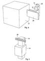
- FIG 3 such integration is illustrated.
- a mounting frame 22 which may be the tube 11 disclosed in FIG 1 lens 14 with reflecting layer is mounted by means of a connection element 23.
- Light source 16 such as an LED or RCLED is mounted on frame 22 by means of a miniature motor 24 such as a piezoelectric motor including a slide 25 which is movable in the vertical direction the light source 16 being supported by the slide.
- the light source accordingly can be shifted vertically to different positions by means of the motor, and the operation of the motor is controlled by output signals from a computer so that the light spot generated by the light source when observed from a defined fixed position at the right end of the sight will be positioned automatically in dependence of relevant parameters supplied to the computer, such that the sight line will intersect the ballistic curve on the target.
- Motor 24 can be located in a box at the lower side of frame 22 so that only slide 25 with light source 16 at the upper end thereof projects from the upper side of the frame.
- FIG 3 only the position along a vertical axis, the Y-axis, is controlled.
- motor 24 having light source 16 mounted to slide 25 thereof, also the position along a horizontal axis, the X-axis, is automatically controlled.
- motor 24 is mounted to the slide 26 of a second motor 27, slide 26 being movable along the X-axis by means of motor 27 while slide 25 is movable along the Y-axis by means of motor 24.
- Light source 16 accordingly can be adjusted in two mutually perpendicular directions by means of the two motors 24 and 27.
- the same result can be achieved by means of a single motor 24 if the light source is a diode array (Vertical Cavity Surface Emitting Laser, VCSEL) 28 mounted to slide 25 of motor 24, as shown in Fig. 5 .
- the slide is movable by means of motor 24 along the Y-axis, and the diode array extends at right angles to slide 25, i.e. along the X-axis. In this case the position vertically is controlled by motor 24 while the position horizontally is controlled by activating the proper diode in diode array 28.
- VCSEL Very Cavity Surface Emitting Laser
- motor 24 is mounted with the associated slide 25 movable along the X-axis while diode array 28 extends along the Y-axis.
- slide 25 to which light source 16 is mounted, is displaceable axially in a tube 29 fixedly mounted to frame 22.
- a two-armed lever 30 is pivoted on a fixed support 31 at 32.
- One arm of the lever supports slide 25 at the lower end thereof, the other arm being engaged from below by a piezoelectric element 33 which is controlled by electric current supplied at 34.
- the piezoelectric element will be lengthened or shortened by the voltage applied to the element being changed, in order to adjust the vertical position of the light source.
- the piezoelectric element 33 in the embodiment described with reference to FIG 6 can be replaced by a magnetostrictive element.
- a pinion 35 on an electric stepping motor 36 engages a rack 37 on slide 25.
- Stepping motor 36 is energized at 34 to rotate in either direction in order to adjust the vertical position of light source 16 by axial displacement of slide 25 in tube 29.
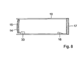
- FIG 8 another embodiment of an adjustable sight according to the present invention is shown.
- the LED is fix in the tube 10, which tube simultaneously serves as an inner tube and as an outer tube.
- the sight adjustment is performed by changing the angle of the double lens 14 by means of the piezo-electric stack 33.
- an elongation of the piezoelectric stack 33 will shift the sight line upwards, i.e. the bullet will hit the target on a lower spot.
- the piezo-electric stack 33 is placed on the upper part of the tube 10, which will give a lower sight line when the piezo-electric stack is elongated, i.e. a higher bullet hit position.
- the embodiment according to figure 8 is advantageous in that the diameter of the tube 8 can be kept at a minimum.
- the translation of the double lens 14 can be performed by other means than a piezo-electric stack, e.g. all other linear movement means that have been described in connection with the other embodiments of the invention.
Landscapes
- Physics & Mathematics (AREA)
- Engineering & Computer Science (AREA)
- General Engineering & Computer Science (AREA)
- Optics & Photonics (AREA)
- Astronomy & Astrophysics (AREA)
- General Physics & Mathematics (AREA)
- Telescopes (AREA)
- Aiming, Guidance, Guns With A Light Source, Armor, Camouflage, And Targets (AREA)
Abstract
Description
- The invention relates to a weapon sight to be used on rifles, guns, and machine guns.
- The weapon sight is of the kind comprising a lens having a partially reflecting surface; a light source spaced from the lens for emitting light towards said reflecting surface to produce a light spot by direct imaging of said light source on said surface to be superimposed on a target when sighting through the lens; and means for adjustment of the location of the light spot on the reflecting surface when observed from a defined fixed position in two mutually perpendicular directions.
- A weapon sight of the kind referred to is disclosed in
GB-A-2 292 465 - Usually, the lens is located at one end of a light channel formed by an elongate housing, and the light source is located in the channel. At sighting, the light spot and the target are observed through the light channel from the other end thereof.
- If the sight at zeroing has been calibrated for a distance from the weapon (sight) to the target of 100 m the ballistic curve of the projectile and the sight line will intersect at the distance 100 m. At very short range (up to 20 m, depending on the distance between the weapon barrel of the and the sight), the ballistic curve will pass under the sight line; between 20 m and 100 m, the ballistic curve will pass over the sight line, whereas the ballistic curve will pass under the sight line at distances longer than 100 m.
- It is desired to compensate automatically for said deviation at other distances than that the sight has been calibrated for by zeroing. However, weapons are used not only for shooting more or less horizontally but also for shooting at an angle upwards or, more often, downwards e. g. from a helicopter. Also a moving target may be aimed at. It is therefore desired to adjust the sight automatically not only for the different distances to the target but also in dependence of the different parameters involved in sighting under the conditions mentioned. At the present state of the art miniature range finders of infrared type as well as miniature angular gauges are available. The present state of the art also includes binoculars with integrated compass. Measurement of the direction in which the shooter is aiming in combination with measurement of the distance to a moving target enables calculation of the speed at which the target moves. Alternatively, the speed can be measured by GPS (global positioning system). With the parameters easily available the aiming point can be controlled in dependence thereof in order to have the weapon directed in different positions towards a target, even towards a moving target, located at different distances from the shooter. However, control of the aiming point by mechanical adjustment thereof to different positions in different directions in dependence of said parameters involves great complications.
- The primary object of the invention is to provide a sight of the kind referred to above with increased possibilities to take into consideration several parameters simultaneously for automatic adjustment of the light spot vertically as well as horisontally.
- A further object is to increase the precision and speed of the adjustment and to facilitate the use of the sight.
- According to the invention these and other objects which will be apparent from the description which follows are achieved by a sight of the kind referred to herein, which according to claim 1 is characterised in that said means for adjustment of the location of the light spot on the reflecting surface comprises a miniature drive motor operatively connected with the light source or the lens, respectively, for displacement of the light source or the lens in one of said two mutually perpendicular directions.
- Further features of the invention are defined in the dependent claims.
- Illustrative embodiments of the sight of the invention will be described in more detail in the following description with reference to the accompanying drawings in which
- FIG 1 is a diagrammatic axial cross sectional view of a weapon sight of the kind referred to herein,
-
FIG 2 is a graph showing the sight line and the ballistic curve of a projectile, -
FIG 3 is a diagrammatic side view of the weapon sight of the invention, -
FIG 4 is an enlarged perspective view of the light source and a supporting structure thereof according to a first embodiment of the invention -
FIG 5 is an enlarged perspective view of a light source comprising a diode array (VCSEL), and the supporting structure thereof according to a second embodiment of the invention, -
FIG 6 is a diagrammatic view of the light source and the supporting structure according to a third embodiment of the invention, -
FIG 7 is a diagrammatic view of the light source and the supporting structure according to a fourth embodiment of the invention, and -
Fig 8 is a diagrammatic view of another embodiment of the present invention. - The weapon sight disclosed in
FIG 1 is of a well known prior art embodiment comprising a light channel formed by anouter tube 10 to be fastened to the barrel, the breechblock, or a specially designed sight holder of a weapon on which the sight shall be used, and aninner tube 11 which is mounted in the outer tube at oneend 12 and is fixed at the other end by adjustment means 13, allowing adjustment of the longitudinal axis of the inner tube horizontally and vertically in relation to the longitudinal axis of the outer tube as is necessary in order to adapt the sight to the weapon on which it is used. In said one end of the inner tube adouble lens 14 is provided having alayer 15 between the lenses, said layer reflecting red light. Inside the inner tube alight source 16 e.g. an LED (Light Emitting Diode) or RCLED (Resonant Cavity Light Emitting Diode) is mounted to project a beam of red light with minimal dispersion onlayer 15 where the light beam forms a red spot to be used as an aiming point. The light beam is reflected by thelayer 15 through a face-ground glass plate 17 having an anti-reflection layer on the side thereof facing the right end of the light channel. Sighting takes place through the light channel formed by the inner tube from the right end thereof the sight line being indicated by a dot-and-dash line 18. - Adjustment of the sight at zeroing could be effected with the sight adjusted for a distance to the target of 100 m. Since the ballistic curve described by the projectile deviates downwards from the weapon along a parabola the sight should be adjusted such that the ballistic curve and the sight line intersect at the distance 100 m. This is illustrated in
FIG 2 wherein the horizontal is indicated at H, the sight line at S and the ballistic curve at B. The sight is shown at 19 and the barrel of the weapon on which the sight is mounted is fragmentarily shown at 20. The distance of 100 m from the weapon is indicated by a dash-dotted line D. The intersection between the sight line and the ballistic curve is indicated at 21. - If the sight line and the ballistic curve do not intersect at a distance of 100 m at zeroing of a weapon having a sight of the type disclosed in
FIG 1 theadjustment mechanism 13 is used to adjust the sight line to such position that the intersection will be located at 100 m. The adjustment mechanism is then calibrated so that it indicates a distance of 100 m. - In some cases, it is useful to adjust the sight so that the bullet will ram the target 3-5 cm above the line of sight at 100 m. By this, it is achieved that the shooter has got some security against misjudgment of the distance to the target; for most popular hunting and military caliber's, a zeroing according to the above will increase the useful range of the weapon up to about 230 m.
- When the weapon with the sight described is being used at even longer distances, the light source has to be adjusted in order to have the sight line and the ballistic curve to intersect at the actual distance. However, the distance is only one parameter that has to be taken into consideration. Other parameters are the angle between the sight line and the horizontal, the speed of a moving target, influence of the wind, the speed of the projectile, the temperature of the air, and the type of ammunition used in the weapon.
- At the present state of the art these parameters can be determined and be processed by a computer for controlling the position of the light source vertically and horizontally in dependence of the determined values of the parameters involved. Miniature drive motors such us piezoelectric or magnetostrictive motors or elements, stepping motors, and linear motors, are available today and are small enough to be integrated with a sight of the kind referred to herein.
- In
FIG 3 such integration is illustrated. On amounting frame 22 which may be thetube 11 disclosed inFIG 1 lens 14 with reflecting layer is mounted by means of aconnection element 23.Light source 16 such as an LED or RCLED is mounted onframe 22 by means of aminiature motor 24 such as a piezoelectric motor including aslide 25 which is movable in the vertical direction thelight source 16 being supported by the slide. The light source accordingly can be shifted vertically to different positions by means of the motor, and the operation of the motor is controlled by output signals from a computer so that the light spot generated by the light source when observed from a defined fixed position at the right end of the sight will be positioned automatically in dependence of relevant parameters supplied to the computer, such that the sight line will intersect the ballistic curve on the target. - Motor 24 can be located in a box at the lower side of
frame 22 so that only slide 25 withlight source 16 at the upper end thereof projects from the upper side of the frame. - In
FIG 3 , only the position along a vertical axis, the Y-axis, is controlled. In the embodiment disclosed inFIG 4 motor 24 havinglight source 16 mounted to slide 25 thereof, also the position along a horizontal axis, the X-axis, is automatically controlled. InFIG 4 motor 24 is mounted to theslide 26 of asecond motor 27,slide 26 being movable along the X-axis by means ofmotor 27 whileslide 25 is movable along the Y-axis by means ofmotor 24.Light source 16 accordingly can be adjusted in two mutually perpendicular directions by means of the twomotors - The same result can be achieved by means of a
single motor 24 if the light source is a diode array (Vertical Cavity Surface Emitting Laser, VCSEL) 28 mounted toslide 25 ofmotor 24, as shown inFig. 5 . The slide is movable by means ofmotor 24 along the Y-axis, and the diode array extends at right angles to slide 25, i.e. along the X-axis. In this case the position vertically is controlled bymotor 24 while the position horizontally is controlled by activating the proper diode indiode array 28. - In a modification of this
embodiment motor 24 is mounted with the associatedslide 25 movable along the X-axis whilediode array 28 extends along the Y-axis. - In the embodiment disclosed in
FIG 6 slide 25, to whichlight source 16 is mounted, is displaceable axially in atube 29 fixedly mounted to frame 22. A two-armed lever 30 is pivoted on a fixedsupport 31 at 32. One arm of the lever supportsslide 25 at the lower end thereof, the other arm being engaged from below by apiezoelectric element 33 which is controlled by electric current supplied at 34. The piezoelectric element will be lengthened or shortened by the voltage applied to the element being changed, in order to adjust the vertical position of the light source. - The
piezoelectric element 33 in the embodiment described with reference toFIG 6 can be replaced by a magnetostrictive element. - In the embodiment according to
FIG 7 , a pinion 35 on anelectric stepping motor 36 engages arack 37 onslide 25. Steppingmotor 36 is energized at 34 to rotate in either direction in order to adjust the vertical position oflight source 16 by axial displacement ofslide 25 intube 29. - In
figure 8 , another embodiment of an adjustable sight according to the present invention is shown. Here, the LED is fix in thetube 10, which tube simultaneously serves as an inner tube and as an outer tube. The sight adjustment is performed by changing the angle of thedouble lens 14 by means of the piezo-electric stack 33. In the embodiment shown, an elongation of thepiezoelectric stack 33 will shift the sight line upwards, i.e. the bullet will hit the target on a lower spot. In another embodiment, the piezo-electric stack 33 is placed on the upper part of thetube 10, which will give a lower sight line when the piezo-electric stack is elongated, i.e. a higher bullet hit position. The embodiment according tofigure 8 is advantageous in that the diameter of the tube 8 can be kept at a minimum. Obviously, the translation of thedouble lens 14 can be performed by other means than a piezo-electric stack, e.g. all other linear movement means that have been described in connection with the other embodiments of the invention. - Finally, one further embodiment will be described. In some cases, it could be useful to combined the diode array of
figure 5 with the movable lens offig. 8 . By combining these two embodiments, side correction of the sight line can be achieved by lighting different diodes of the diode array, whereas horizontal correction of the sight line can be achieved by means of the movable lens. Of course, it is also possible to use both a moving light source and a moving lens. - Within the scope of the invention the embodiments described above may be combined in different ways, or one embodiment may be modified by guidance of another embodiment described herein.
Claims (9)
- A weapon sight of the kind comprising a lens (14) having a partially reflecting surface; a light source (16, 28) spaced from the lens for emitting light towards said reflecting surface to produce a light spot by direct imaging of said light source on said surface to be superimposed on a target when sighting through the lens; and means (24, 27, 29) for adjustment of the location of the light spot on the reflecting surface when observed from a defined fixed position, in two mutually perpendicular directions, characterized in that said means for adjustment of the location of the light spot on the reflecting surface comprises a miniature drive motor operatively connected with the light source (16,28) or the lens (14), respectively, for displacement of the light source (16, 28) or the lens (14) in one of said two mutually perpendicular directions.
- The weapon sight of claim 1 wherein said miniature drive motor comprises a piezoelectric element.
- The weapon sight of claim 1 wherein said miniature drive motor comprises a magnetostrictive element.
- The weapon sight of claim 1 wherein said miniature drive motor comprises a stepping motor.
- The weapon sight of claim 1 further comprising a second miniature drive motor operatively connected with the light source (16, 28) or the lens (14) for displacement of the light source (16, 28) or the lens (14), respectively, in the other one of said two mutually perpendicular directions.
- The weapon sight of claim 5 wherein said second miniature drive motor comprises a piezoelectric element.
- The weapon sight of claim 5 wherein said second miniature drive motor comprises a magnetostrictive element.
- The weapon sight of claim 5 wherein said second miniature drive motor comprises a stepping motor.
- The weapon sight of claim 1 wherein the light source comprises an LED array (28) extending in the other one of said two mutually perpendicular directions.
Applications Claiming Priority (3)
| Application Number | Priority Date | Filing Date | Title |
|---|---|---|---|
| SE0201932 | 2002-06-24 | ||
| SE0201932A SE524172C2 (en) | 2002-06-24 | 2002-06-24 | weapon sight |
| PCT/SE2003/001069 WO2004001324A1 (en) | 2002-06-24 | 2003-06-23 | Weapon sight |
Publications (2)
| Publication Number | Publication Date |
|---|---|
| EP1516151A1 EP1516151A1 (en) | 2005-03-23 |
| EP1516151B1 true EP1516151B1 (en) | 2012-06-20 |
Family
ID=20288290
Family Applications (1)
| Application Number | Title | Priority Date | Filing Date |
|---|---|---|---|
| EP03733784A Expired - Lifetime EP1516151B1 (en) | 2002-06-24 | 2003-06-23 | Weapon sight |
Country Status (5)
| Country | Link |
|---|---|
| US (1) | US7764434B2 (en) |
| EP (1) | EP1516151B1 (en) |
| AU (1) | AU2003239070A1 (en) |
| SE (1) | SE524172C2 (en) |
| WO (1) | WO2004001324A1 (en) |
Cited By (2)
| Publication number | Priority date | Publication date | Assignee | Title |
|---|---|---|---|---|
| US10907934B2 (en) | 2017-10-11 | 2021-02-02 | Sig Sauer, Inc. | Ballistic aiming system with digital reticle |
| US11454473B2 (en) | 2020-01-17 | 2022-09-27 | Sig Sauer, Inc. | Telescopic sight having ballistic group storage |
Families Citing this family (13)
| Publication number | Priority date | Publication date | Assignee | Title |
|---|---|---|---|---|
| US7325318B2 (en) | 2005-09-22 | 2008-02-05 | Cubic Corporation | Compact multifunction sight |
| US7355790B1 (en) * | 2006-08-04 | 2008-04-08 | Raytheon Company | Optical sight having a reticle illuminated through a non-lambertian light diffuser |
| US9557140B2 (en) | 2008-01-24 | 2017-01-31 | Aimpoint Ab | Sight |
| SE534612C2 (en) | 2009-07-08 | 2011-10-25 | Gs Dev Ab | Fire control systems |
| US20140264020A1 (en) | 2013-03-14 | 2014-09-18 | Rochester Precision Optics, Llc | Compact thermal aiming sight |
| PL3019812T3 (en) | 2013-07-09 | 2019-04-30 | Zieger Cory | Modular holographic sighting system |
| US20150029567A1 (en) * | 2013-07-15 | 2015-01-29 | OptiFlow, Inc. | Folding holographic sight for a gun |
| WO2015009720A2 (en) * | 2013-07-15 | 2015-01-22 | OptiFlow, Inc. | Gun sight |
| US10254532B2 (en) | 2015-06-26 | 2019-04-09 | Ziel Optics, Inc. | Hybrid holographic sight |
| US10247515B2 (en) | 2015-06-26 | 2019-04-02 | Ziel Optics, Inc. | Holographic sight with optimized reflection and image angles |
| EP3390955B1 (en) * | 2015-12-18 | 2021-09-22 | Optiflow, LLC | Combination reflective and holographic weapon sight |
| US11604344B2 (en) * | 2018-09-03 | 2023-03-14 | Light Optical Works, Ltd. | Dot sight |
| TWI699572B (en) * | 2019-04-18 | 2020-07-21 | 大陸商信泰光學(深圳)有限公司 | Optical device |
Family Cites Families (15)
| Publication number | Priority date | Publication date | Assignee | Title |
|---|---|---|---|---|
| US2596522A (en) * | 1950-06-10 | 1952-05-13 | Clarence E Bethke | Illuminated gun sight |
| SE371491B (en) * | 1973-03-26 | 1974-11-18 | J Ekstrand | |
| US3951553A (en) * | 1974-10-07 | 1976-04-20 | The Perkin-Elmer Corporation | Apparatus for aiming a gun |
| SE428605B (en) * | 1979-03-19 | 1983-07-11 | Aimpoint Ab | OPTICAL GUIDELINES FOR FIREARMS |
| US4665622A (en) * | 1985-11-18 | 1987-05-19 | Elbit Computers, Ltd. | Optical sighting device |
| US4919528A (en) * | 1987-09-10 | 1990-04-24 | The Boeing Company | Boresight alignment verification device |
| DE4003932A1 (en) * | 1990-02-09 | 1991-08-14 | Messerschmitt Boelkow Blohm | METHOD FOR VISOR ADJUSTMENT IN WEAPON SYSTEMS |
| US5205044A (en) * | 1991-11-12 | 1993-04-27 | Depaoli Alfred C | Luminous dot sighting instrument |
| US5369888A (en) * | 1993-01-13 | 1994-12-06 | Kay; Ira M. | Wide field of view reflex gunsight |
| SE9300782L (en) * | 1993-03-10 | 1994-06-13 | Sandberg Dev Ab | Firearms targeting |
| GB2292465A (en) * | 1994-03-02 | 1996-02-21 | Clive Rawlinson Paige | Optical sight with part-reflective aspheric surface and mount |
| JP3188277B2 (en) * | 1996-07-05 | 2001-07-16 | ファウエルゲー・バーチャル・レーザー・ゲームズ・ゲーエムベーハー | Computer controlled game system |
| SE512276C2 (en) * | 1997-10-09 | 2000-02-21 | Gs Dev Ab | Light emitting device |
| US6154971A (en) * | 1998-07-01 | 2000-12-05 | Perkins; Ronald Keith | Sight apparatus |
| SE518587C2 (en) * | 2001-01-09 | 2002-10-29 | Gs Dev Ab | Optical sight |
-
2002
- 2002-06-24 SE SE0201932A patent/SE524172C2/en not_active IP Right Cessation
-
2003
- 2003-06-23 AU AU2003239070A patent/AU2003239070A1/en not_active Abandoned
- 2003-06-23 EP EP03733784A patent/EP1516151B1/en not_active Expired - Lifetime
- 2003-06-23 WO PCT/SE2003/001069 patent/WO2004001324A1/en not_active Ceased
-
2004
- 2004-12-16 US US11/012,314 patent/US7764434B2/en not_active Expired - Lifetime
Cited By (5)
| Publication number | Priority date | Publication date | Assignee | Title |
|---|---|---|---|---|
| US10907934B2 (en) | 2017-10-11 | 2021-02-02 | Sig Sauer, Inc. | Ballistic aiming system with digital reticle |
| US11287218B2 (en) | 2017-10-11 | 2022-03-29 | Sig Sauer, Inc. | Digital reticle aiming method |
| US11725908B2 (en) | 2017-10-11 | 2023-08-15 | Sig Sauer, Inc. | Digital reticle system |
| US12253332B2 (en) | 2017-10-11 | 2025-03-18 | Sig Sauer, Inc. | Digital reticle system |
| US11454473B2 (en) | 2020-01-17 | 2022-09-27 | Sig Sauer, Inc. | Telescopic sight having ballistic group storage |
Also Published As
| Publication number | Publication date |
|---|---|
| US20100039702A9 (en) | 2010-02-18 |
| SE0201932L (en) | 2003-12-25 |
| EP1516151A1 (en) | 2005-03-23 |
| SE0201932D0 (en) | 2002-06-24 |
| US20050225853A1 (en) | 2005-10-13 |
| SE524172C2 (en) | 2004-07-06 |
| AU2003239070A1 (en) | 2004-01-06 |
| US7764434B2 (en) | 2010-07-27 |
| WO2004001324A1 (en) | 2003-12-31 |
Similar Documents
| Publication | Publication Date | Title |
|---|---|---|
| EP1516151B1 (en) | Weapon sight | |
| US7793456B1 (en) | Gun sight reticle having adjustable sighting marks for bullet drop compensation | |
| US7827723B1 (en) | Lateral de-centering of riflescope objective for aiming adjustment | |
| US8074394B2 (en) | Riflescope with image stabilization | |
| US9033231B2 (en) | Automatic correction apparatus for trajectory of a projectile and correction method using the same | |
| EP3692323B1 (en) | Open frame reflex pivot mechanics | |
| EP3961144B1 (en) | Riflescope with turret encoder controlled laser rangefinder | |
| EP1793195B1 (en) | Improved device for remote control of a weapon. | |
| US5771623A (en) | Telescopic sight | |
| US5491546A (en) | Laser assisted telescopic target sighting system and method | |
| US8256152B2 (en) | Method and apparatus for collimating and coaligning optical components | |
| US20130298438A1 (en) | Method of Movement Compensation for a Weapon | |
| US4266463A (en) | Fire control device | |
| KR20190039508A (en) | Viewfinder with movable red dots and fixtures | |
| GB2322692A (en) | Fire control device for anti-aircraft systems | |
| US20060272194A1 (en) | Firearm for low velocity projectiles | |
| JPH0516572B2 (en) | ||
| US20120311913A1 (en) | Rifle scope with integrated laser sight | |
| AU2017297739B2 (en) | Telescopic sight | |
| US11047647B2 (en) | Firearm and method for improving accuracy | |
| CN210952515U (en) | External tracking laser transceiver | |
| RU2280225C2 (en) | Gun barrel bore direction monitor | |
| CN121206973A (en) | A mechanical aiming device that can be equipped with an electronic measurement and control module | |
| HK1144595B (en) | Improved sight with mobile red dot |
Legal Events
| Date | Code | Title | Description |
|---|---|---|---|
| PUAI | Public reference made under article 153(3) epc to a published international application that has entered the european phase |
Free format text: ORIGINAL CODE: 0009012 |
|
| 17P | Request for examination filed |
Effective date: 20041120 |
|
| AK | Designated contracting states |
Kind code of ref document: A1 Designated state(s): AT BE BG CH CY CZ DE DK EE ES FI FR GB GR HU IE IT LI LU MC NL PT RO SE SI SK TR |
|
| AX | Request for extension of the european patent |
Extension state: AL LT LV MK |
|
| DAX | Request for extension of the european patent (deleted) | ||
| RBV | Designated contracting states (corrected) |
Designated state(s): DE FR GB |
|
| GRAP | Despatch of communication of intention to grant a patent |
Free format text: ORIGINAL CODE: EPIDOSNIGR1 |
|
| GRAS | Grant fee paid |
Free format text: ORIGINAL CODE: EPIDOSNIGR3 |
|
| GRAA | (expected) grant |
Free format text: ORIGINAL CODE: 0009210 |
|
| AK | Designated contracting states |
Kind code of ref document: B1 Designated state(s): DE FR GB |
|
| REG | Reference to a national code |
Ref country code: GB Ref legal event code: FG4D |
|
| REG | Reference to a national code |
Ref country code: DE Ref legal event code: R081 Ref document number: 60341343 Country of ref document: DE Owner name: AIMPOINT AB, SE Free format text: FORMER OWNER: GS DEVELOPMENT AB, MALMOE, SE |
|
| REG | Reference to a national code |
Ref country code: DE Ref legal event code: R096 Ref document number: 60341343 Country of ref document: DE Effective date: 20120816 |
|
| PLBE | No opposition filed within time limit |
Free format text: ORIGINAL CODE: 0009261 |
|
| STAA | Information on the status of an ep patent application or granted ep patent |
Free format text: STATUS: NO OPPOSITION FILED WITHIN TIME LIMIT |
|
| 26N | No opposition filed |
Effective date: 20130321 |
|
| REG | Reference to a national code |
Ref country code: DE Ref legal event code: R097 Ref document number: 60341343 Country of ref document: DE Effective date: 20130321 |
|
| REG | Reference to a national code |
Ref country code: FR Ref legal event code: PLFP Year of fee payment: 13 |
|
| REG | Reference to a national code |
Ref country code: DE Ref legal event code: R082 Ref document number: 60341343 Country of ref document: DE Representative=s name: PAUL & ALBRECHT PATENTANWALTSSOZIETAET, DE Ref country code: DE Ref legal event code: R081 Ref document number: 60341343 Country of ref document: DE Owner name: AIMPOINT AB, SE Free format text: FORMER OWNER: GS DEVELOPMENT AB, MALMOE, SE Ref country code: DE Ref legal event code: R082 Ref document number: 60341343 Country of ref document: DE Representative=s name: PAUL & ALBRECHT PATENTANWAELTE PARTG MBB, DE |
|
| REG | Reference to a national code |
Ref country code: GB Ref legal event code: 732E Free format text: REGISTERED BETWEEN 20160512 AND 20160518 |
|
| REG | Reference to a national code |
Ref country code: FR Ref legal event code: PLFP Year of fee payment: 14 |
|
| REG | Reference to a national code |
Ref country code: FR Ref legal event code: TP Owner name: AIMPOINT AB, SE Effective date: 20160926 |
|
| REG | Reference to a national code |
Ref country code: FR Ref legal event code: PLFP Year of fee payment: 15 |
|
| REG | Reference to a national code |
Ref country code: FR Ref legal event code: PLFP Year of fee payment: 16 |
|
| PGFP | Annual fee paid to national office [announced via postgrant information from national office to epo] |
Ref country code: GB Payment date: 20220616 Year of fee payment: 20 Ref country code: DE Payment date: 20220607 Year of fee payment: 20 |
|
| PGFP | Annual fee paid to national office [announced via postgrant information from national office to epo] |
Ref country code: FR Payment date: 20220627 Year of fee payment: 20 |
|
| REG | Reference to a national code |
Ref country code: DE Ref legal event code: R071 Ref document number: 60341343 Country of ref document: DE |
|
| P01 | Opt-out of the competence of the unified patent court (upc) registered |
Effective date: 20230530 |
|
| REG | Reference to a national code |
Ref country code: GB Ref legal event code: PE20 Expiry date: 20230622 |
|
| PG25 | Lapsed in a contracting state [announced via postgrant information from national office to epo] |
Ref country code: GB Free format text: LAPSE BECAUSE OF EXPIRATION OF PROTECTION Effective date: 20230622 |