EP1515551A2 - Projection type display device - Google Patents
Projection type display device Download PDFInfo
- Publication number
- EP1515551A2 EP1515551A2 EP04020039A EP04020039A EP1515551A2 EP 1515551 A2 EP1515551 A2 EP 1515551A2 EP 04020039 A EP04020039 A EP 04020039A EP 04020039 A EP04020039 A EP 04020039A EP 1515551 A2 EP1515551 A2 EP 1515551A2
- Authority
- EP
- European Patent Office
- Prior art keywords
- image
- tilt angle
- display device
- fixed point
- screen
- Prior art date
- Legal status (The legal status is an assumption and is not a legal conclusion. Google has not performed a legal analysis and makes no representation as to the accuracy of the status listed.)
- Ceased
Links
Images




Classifications
-
- H—ELECTRICITY
- H04—ELECTRIC COMMUNICATION TECHNIQUE
- H04N—PICTORIAL COMMUNICATION, e.g. TELEVISION
- H04N9/00—Details of colour television systems
- H04N9/12—Picture reproducers
- H04N9/31—Projection devices for colour picture display, e.g. using electronic spatial light modulators [ESLM]
- H04N9/3179—Video signal processing therefor
- H04N9/3185—Geometric adjustment, e.g. keystone or convergence
-
- H—ELECTRICITY
- H04—ELECTRIC COMMUNICATION TECHNIQUE
- H04N—PICTORIAL COMMUNICATION, e.g. TELEVISION
- H04N5/00—Details of television systems
- H04N5/74—Projection arrangements for image reproduction, e.g. using eidophor
Definitions
- the present invention relates to a projection type display device such as a liquid crystal projector, and more particularly, to a projection type display device which allows an user to readily correct an optical image for distortions which are produced when an optical image is enlarged and projected on a screen with a tilt angle in the vertical and horizontal directions through a projection lens.
- a projection type display device is typically placed below the center of a screen for projecting an enlarged image with a projection lens oriented upward.
- the image projected on the screen suffers from an inverse trapezoidal distortion (trapezoidal having an upper side longer than a lower side).
- the projection type display device is placed at an angle in the horizontal direction (lateral direction) to the screen, the projected image further extends toward an upper left side or an upper right side to present a more complicated trapezoidal distortion.
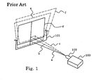
- Fig. 1 shows the relationship between the placement of the projection type display device and an image projected on the screen.
- the image projected on screen 101 reproduces original rectangular image d without tilt distortions when the image is projected from projection lens 102 of projection type display device 100 along projection optical axis a without tilt to screen 101.
- display device 100 provides vertically tilted image e in an inverse trapezoidal shape.
- the resulting image further extends toward an upper right side to present horizontally and vertically tilted image f which has more complicated distortions.
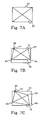
- a correction for a trapezoidal distortion which is produced when projection type display device 100 is positioned as shown in Fig. 1 (projection lens 102 is oriented upward and tilted to the right), will be described with reference to Figs. 2A to 2C.
- Figs. 2A to 2C are diagrams for describing how an image is corrected for a trapezoidal distortion.
- Figs. 2A, 2B illustrate image 113 displayed within image display range 115 on an image display device (liquid crystal panel) when a vertical correction is made.
- Displayed image 113 on an image display device (not shown) is distorted in a direction opposite to an inverse trapezoidal distortion of the image 101 projected on the screen to correct the projected image for the distortion, resulting in a rectangle.
- the correction for a vertical distortion involves increasing a compression ratio of a line corresponding to the upper side of the projected image on the displayed image, on the image display device, and reducing the compression rate toward the lower side.
- Figs. 2B, 2C illustrate image 113 displayed on the image display device when it is subjected to a horizontal correction after the vertical correction.
- a transition from Fig. 2A to Fig. 2B implies movements of upper left vertex P101 and upper right vertex P102
- a transition from Fig. 2B to Fig. 2C implies movements of lower left vertex P103 and lower right vertex P104, eventually resulting in movements of all four vertexes P101, P102, P103, P104.
- the user When an user corrects an image for distortions, the user typically matches the vertexes of the image with the vertexes of screen 101 before the correction for the distortion, so that the vertexes of the image move each time a vertical correction or a horizontal correction is made as illustrated in Fig. 2A to 2C, resulting in difficulty in correction for the distortion.
- JP-A-198993/2003 discloses a projection type display device which collectively corrects an image for distortion produced when the image is projected at tilt angles in two directions, i.e., for a trapezoidal distortion produced when the image is projected at an tilt angle in the vertical direction, and for a trapezoidal distortion when the image is projected at an tilt angle in the horizontal direction.
- This projection type display device comprises a tilt sensor for detecting a tilt angle in the vertical direction, and a rotary knob manipulated by the user to correct an image for distortions in the horizontal direction. The result detected by the tilt sensor is applied to a distortion correcting circuit through a microcomputer to automatically correct the image for distortions in the vertical direction.
- a voltage which varies in accordance with rotating angles of the rotary knob is applied to the microcomputer which converts the voltage to data related to a horizontal tilt angle set by the user, and the data is applied to the distortion correcting circuit.
- the microcomputer which converts the voltage to data related to a horizontal tilt angle set by the user
- the data is applied to the distortion correcting circuit.
- a correction is made by rotating in the reverse direction the scaled rotary knob by an angle equal to an angle by which the display device is tilted in the horizontal direction.
- the correction of an image for distortions entails difficult manipulations, so that an user must attain proficiency in the manipulations.
- a projection type display device includes an image display device for processing an input image and displaying the processed image, a projection lens for enlarging a display image of the image display device for display on a screen as a projected image, a distortion corrector for correcting the projected image for distortions when the display image is projected with a projection optical axis tilted with respect to the screen, an angle detector for detecting a tilt angle of the projection optical axis in the vertical direction, and a user interface having a controller for correcting the projected image for distortions in the horizontal direction.
- the distortion corrector includes a tilt angle generator for receiving outputs from the angle detector and the user interface to find the tilt angle of the projection optical axis of the projection lens with respect to the screen, and a display image corrector for correcting the display image using the tilt angle.
- the display image corrector includes a processor for finding four vertexes using a two-dimensional table having corrected coordinates for the four vertexes of the display image or a mathematical expression, wherein the two-dimensional table or the mathematical expression employ a vertical tilt angle and a horizontal tilt angle as variables and, and a fixed point determiner for selecting one of the four vertex as a fixed point.
- the projection type display device of the present invention selects one of vertexes of a quadrilateral represented by a projected optical image as a fixed point, and make the vortex immobile even if the image is corrected for distortions, thereby allowing an user to readily correct the image for distortions.
- the distortion corrector includes an arrow image generator for generating an image of an arrow, and an arrow positioner for displaying the image of the arrow for the fixed point determined by an input signal from the fixed point determiner.
- the corrected image and an output from the arrow positioner are combined by an image combiner of a fixed point display to generate an output image which has the arrow superimposed on the corrected image, and the output image is projected on the screen through the projection lens.
- the arrow indicates the fixed point which is determined from the tilt of the projection optical axis with respect to the screen, whether it is right-up tilt, left-up tilt, left-down tilt, or right-down tilt, the user can recognize the fixed point by view and therefore can visually and readily make a correction for distortions.
- Fig. 3 is a block diagram generally illustrating the configuration of a projection type display device according to the present invention
- Fig. 4 is a diagram showing the relationship between a screen and a projection optical axis of the projection type display device.
- projection type display device 1 comprises image display device 7 for processing input image 6 and displaying the processed image; projection lens 2 for enlarging the display image produced by image display device 7 and displaying it on screen 10 as projected image 12; distortion corrector 3 for correcting projected image 12 for distortions which are produced when the display image is projected on screen 10 along an axis tilted to axis 2a; acceleration sensor 5 for detecting a tilt angle of projection optical axis in the vertical direction; and user interface 4 having a controller (not shown) for correcting an image for distortions in the horizontal direction.
- Distortion corrector 3 comprises tilt angle generator 31 for finding a tilt angle of projection optical axis of projection lens 2 with respect to screen 10 and receives outputs from acceleration sensor 5 and user interface 4,; and display image corrector 32 for correcting display image 13 using the tilt angle.
- Display image corrector 32 comprises two-dimensional table 321 which employs a vertical tilt angle and a horizontal tilt angle as variables, and stores corrected coordinates for four vertexes of display image 13; table referrer 322 for obtaining corrected coordinates for four vertexes P1, P2, P3, P4 corresponding to the tilt angle input from tilt angle generator 31 by referring to two-dimensional table 321; and fixed point determiner 323 for selecting one of the four vertexes as fixed point 20. The description of a construction to find corrected coordinates for the four vertexes by calculations is omitted.
- Distortion corrector 3 comprises arrow image generator 33 for generating an image of arrow 19; and arrow positioner 34 for displaying the image of arrow 19 generated by arrow image generator 33 for fixed point 20 determined by an output signal from fixed point determiner 323.
- distortion corrector 3 has a CPU (Central Processing Unit), while display image corrector 32 is implemented by an LSI (Large Scale Integrated Circuit), such that the CPU controls coordinate correction processing of the LSI.
- CPU Central Processing Unit
- LSI Large Scale Integrated Circuit
- An output from display image corrector 32 and input image 6 are processed by image processor 71 (image processing LSI) of image display device 7 to generate and output corrected image 8.
- Corrected image 8 is combined with the output from arrow positioner 34 by image combiner 91 of fixed point display 9. Consequently, output image 11 having arrow 19 superimposed on corrected image 8 is projected on screen 10 through projection lens 2.
- two-dimensional table 321 stores corrected coordinates for four vertexes P1, P2, P3, P4 of display image 13 in a matrix form with vertical tilt angles and horizontal tilt angles used as parameters.
- table referrer 322 for obtaining corrected coordinates reads cell A12 in Fig. 5.
- cell A12 stores two-dimensional corrected coordinates for the four vertexes: P1 (x1,y1), P2(x2,y2), P3(x3,y3), P4(x4,y4) (specific coordinate values for x, y are omitted).
- Fig. 5 shows, as an example, two-dimensional table 321 which corresponds to the state in which projection type display device 1 is tilted in an upper right direction as shown in Fig.4 (projection optical axis in Fig. 4 falls onto first quadrant 25).
- Fig. 5 omits two-dimensional tables 321 corresponding to second quadrant 26, third quadrant 27, and fourth quadrant 28.
- the variables i.e., the vertical tilt angles and horizontal tilt angles may be indicated as an angular range, for example, from zero degree to five degrees, or from five degrees to ten degrees.
- the increments of angles in table 321, as a matter of course, may be set arbitrarily, not limited to five degrees.
- projection type display device 1 configured as described above, will be described with reference to Figs. 7A to 8B.
- Figs. 7A to 7C are diagrams for describing operations for correcting display image 13 when it is projected along a projection optical axis oriented in an obliquely upward right direction with respect to screen 10
- Figs. 8A and 8B are diagrams each for describing image 12 on screen 10, corresponding to Figs. 7B and 7C, respectively.
- Fig. 7A shows that display image 13 is not corrected within image display range 15, and Fig. 7B shows that display image 13 is corrected in the vertical direction.
- Tilt angle generator 31 generates a vertical tilt angle based on the output of accelerator sensor 5.
- Table referrer 323 reads two-dimensional table 321 of display image corrector 32 to obtain corrected coordinates corresponding to the vertical tilt angle (A10 in Fig. 5 is obtained. Corrected coordinates are omitted in the figure) to automatically correct display image 13 in the vertical direction.
- projected image 12 on screen 10 is seen as illustrated in Fig. 8A.
- the user manipulates the controller (not shown) of user interface 4 to correct projected image 12 for distortions due to the tilt angle in the horizontal direction.
- the horizontal tilt angle is detected by a rotary encoder (not shown) or the like provided in user interface 4, and a horizontal tilt angle is generated by tilt angle generator 31 using the horizontal tilt angle.
- table referrer 322 reads two-dimensional table 321 of display image corrector 32 to obtain corrected coordinates corresponding to the horizontal tilt angle (A12 in Fig. 5 is obtained) to correct display image 13 for distortions in the horizontal direction.
- the corrected coordinates for the four vertexes obtained in this event are P1 (x1,y1), P2(x2,y2), P3(x3,y3), P4(x4,y4).
- fixed point determiner 323 selects one of four vertexes P1 - P4 as fixed point 20. Specifically, upper left vertex P1 is selected as fixed point 20 when an image is projected along a projection optical axis oriented in an obliquely upward right direction with respect to screen 10; upper right vertex P2 is selected when axis is tilted in an obliquely upward left direction; lower right vertex P4 is selected when projection optical axis is tilted in an obliquely downward left direction; and lower left vertex P3 is selected when axis is tilted in an obliquely downward right direction (see Fig. 9).
- Fixed point determiner 323 is arranged in advance to select upper left vertex P1 as fixed point 20 when two-dimensional table 321 from which the corrected coordinates are obtained corresponds to first quadrant 25; upper right vertex P2 when table 321 corresponds to second quadrant 26; lower right vertex P4 when table 321 corresponds to third quadrant 27; and lower left vertex P3 when table 321 corresponds to fourth quadrant 28.
- upper left vertex P1 is selected as fixed point 20 and is therefore made immobile.
- projected image 12 is corrected as shown in Fig. 8B. In this way, the user can quite readily make a correction for distortions in the horizontal direction.
- arrow 19 is displayed to point to fixed point 20 in order for the user to visually recognize fixed point 20. Since fixed point 20 is determined corresponding to the tilt of projection optical axis of projection type display device 1 with respect to screen 10, whether it is right-up tilt, left-up tilt, left-down tilt, or right-down tilt, arrow 19 displayed for indicating fixed point 20 allows the user to more readily and visually make a correction for distortions in the horizontal direction.
Landscapes
- Engineering & Computer Science (AREA)
- Multimedia (AREA)
- Signal Processing (AREA)
- Physics & Mathematics (AREA)
- Geometry (AREA)
- Transforming Electric Information Into Light Information (AREA)
- Projection Apparatus (AREA)
- Video Image Reproduction Devices For Color Tv Systems (AREA)
Abstract
Description
Claims (9)
- A projection type display device comprising:wherein said distortion corrector includes a tilt angle generator for receiving outputs from said angle detector and said user interface to find the tilt angle of the projection optical axis of said projection lens with respect to said screen, and a display image corrector for correcting the display image using the tilt angle, andan image display device for processing an input image and displaying a processed image;a projection lens for enlarging a display image of said image display device for display on a screen as a projected image;a distortion corrector for correcting the projected image for distortions when said display image is projected with a projection optical axis tilted with respect to said screen;an angle detector for detecting a tilt angle of said projection optical axis in a vertical direction; anda user interface having a controller for correcting the projected image for distortions in a horizontal direction,
said display image corrector includes a processor for finding four vertexes using a two-dimensional table having corrected coordinates for the four vertexes of the display image or a mathematical expression, said two-dimensional table or said mathematical expression employing a vertical tilt angle and a horizontal tilt angle as variables , and a fixed point determiner for selecting one of the four vertex as a fixed point. - The projection type display device according to claim 1, wherein:said fixed point is determined such that a coordinate of said vertex does not move in response to a correction for distortions in the horizontal direction.
- The projection type display device according to claim 1 or 2, wherein:said distortion corrector includes an arrow image generator for generating an image of an arrow, and an arrow positioner for displaying the image of the arrow for the fixed point determined by an output signal from said fixed point determiner.
- The projection type display device according to claim 1,2 or 3, wherein:said image display device includes an image processor for processing an output from said display image corrector and the input image to generate a corrected image, and delivering the corrected image.
- The projection type display device according to claim 1,2,3 or 4, further comprising:a fixed point display for combining said corrected image with an output from said arrow positioner by an image combiner to generate an output image which has the arrow superimposed on the corrected image, and projecting said output image on said screen through said projection lens.
- The device according to any one of claims 1 to 5, wherein:said fixed point determiner selects an upper left vertex as the fixed point when the projection optical axis is tilted in an upper right direction with respect to said screen; an upper right vertex when the axis is tilted in an upper left direction; a lower right vertex when the axis is tilted in a lower left direction; and a lower left vertex when the axis is tilted in a lower right direction.
- The device according to any one of claims 1 to 6, wherein said angle detector includes an acceleration sensor.
- The device according to any one of claims 1 to 7, wherein said user interface includes means for detecting a horizontal tilt angle, and means for manually correcting a distortion due to a horizontal tilt angle.
- The device according to any one of claims 1 to 8, wherein said two-dimensional table stores the corrected coordinates for four vertexes of the display image in a matrix form.
Priority Applications (1)
| Application Number | Priority Date | Filing Date | Title |
|---|---|---|---|
| EP08152834A EP1936969A3 (en) | 2003-09-10 | 2004-08-24 | Projection type display device |
Applications Claiming Priority (2)
| Application Number | Priority Date | Filing Date | Title |
|---|---|---|---|
| JP2003318285 | 2003-09-10 | ||
| JP2003318285A JP3827662B2 (en) | 2003-09-10 | 2003-09-10 | Projection display |
Related Child Applications (1)
| Application Number | Title | Priority Date | Filing Date |
|---|---|---|---|
| EP08152834A Division EP1936969A3 (en) | 2003-09-10 | 2004-08-24 | Projection type display device |
Publications (2)
| Publication Number | Publication Date |
|---|---|
| EP1515551A2 true EP1515551A2 (en) | 2005-03-16 |
| EP1515551A3 EP1515551A3 (en) | 2007-08-15 |
Family
ID=34131999
Family Applications (2)
| Application Number | Title | Priority Date | Filing Date |
|---|---|---|---|
| EP04020039A Ceased EP1515551A3 (en) | 2003-09-10 | 2004-08-24 | Projection type display device |
| EP08152834A Withdrawn EP1936969A3 (en) | 2003-09-10 | 2004-08-24 | Projection type display device |
Family Applications After (1)
| Application Number | Title | Priority Date | Filing Date |
|---|---|---|---|
| EP08152834A Withdrawn EP1936969A3 (en) | 2003-09-10 | 2004-08-24 | Projection type display device |
Country Status (4)
| Country | Link |
|---|---|
| US (1) | US7201482B2 (en) |
| EP (2) | EP1515551A3 (en) |
| JP (1) | JP3827662B2 (en) |
| CN (1) | CN100541319C (en) |
Cited By (1)
| Publication number | Priority date | Publication date | Assignee | Title |
|---|---|---|---|---|
| EP2509321A3 (en) * | 2011-04-06 | 2012-11-21 | Canon Kabushiki Kaisha | Projection apparatus, control method thereof, and program |
Families Citing this family (32)
| Publication number | Priority date | Publication date | Assignee | Title |
|---|---|---|---|---|
| JP2005006228A (en) | 2003-06-13 | 2005-01-06 | Casio Comput Co Ltd | projector |
| JP3846592B2 (en) * | 2003-06-26 | 2006-11-15 | セイコーエプソン株式会社 | Image processing system, projector, program, information storage medium, and image processing method |
| JP4155890B2 (en) * | 2003-07-15 | 2008-09-24 | カシオ計算機株式会社 | Projector, projector tilt angle acquisition method, and projection image correction method |
| JP3969363B2 (en) * | 2003-07-30 | 2007-09-05 | カシオ計算機株式会社 | Projector and projection image correction method for projector |
| JP4196951B2 (en) * | 2005-02-04 | 2008-12-17 | セイコーエプソン株式会社 | Projector, projected image adjustment method |
| US7130095B1 (en) * | 2005-06-24 | 2006-10-31 | Symbol Technologies, Inc. | Correcting for image distortion in image projectors |
| JP2007036482A (en) * | 2005-07-25 | 2007-02-08 | Nippon Telegr & Teleph Corp <Ntt> | Information projection display device and program |
| JP2007067495A (en) * | 2005-08-29 | 2007-03-15 | Toshiba Corp | Projector device |
| KR100747012B1 (en) | 2005-09-26 | 2007-08-07 | 삼성전기주식회사 | Image distortion correction method and scanning display device using the same |
| CN1976482B (en) * | 2005-11-28 | 2010-09-08 | 上海科技馆 | Irregular stereo-curtain projecting method |
| KR100827619B1 (en) | 2006-10-11 | 2008-05-07 | 삼성전기주식회사 | Image distortion correction method and device |
| KR100812997B1 (en) * | 2007-03-07 | 2008-03-13 | 삼성전기주식회사 | Keystone correction method and display device |
| JP5481833B2 (en) * | 2008-10-29 | 2014-04-23 | セイコーエプソン株式会社 | Projector and projector control method |
| US8297757B2 (en) * | 2008-10-29 | 2012-10-30 | Seiko Epson Corporation | Projector and projector control method |
| US8698747B1 (en) | 2009-10-12 | 2014-04-15 | Mattel, Inc. | Hand-activated controller |
| US8322863B1 (en) * | 2010-06-18 | 2012-12-04 | Samuel Seungmin Cho | Apparatus and method for automated visual distortion adjustments for a portable projection device |
| US8919965B2 (en) * | 2010-07-02 | 2014-12-30 | At&T Intellectual Property I, L.P. | Image stabilization and skew correction for projection devices |
| CN102109972B (en) * | 2011-02-14 | 2012-09-12 | 深圳雅图数字视频技术有限公司 | Projector television wall display method and system |
| CN102271237A (en) * | 2011-02-25 | 2011-12-07 | 鸿富锦精密工业(深圳)有限公司 | Projection device and method for correcting trapezoidal distortion |
| EP2498490A1 (en) * | 2011-03-11 | 2012-09-12 | Panasonic Corporation | Image display apparatus and portable information processing apparatus having the same |
| JP5453352B2 (en) * | 2011-06-30 | 2014-03-26 | 株式会社東芝 | Video display device, video display method and program |
| JP5982787B2 (en) * | 2011-11-02 | 2016-08-31 | 株式会社リコー | projector |
| JP5891714B2 (en) * | 2011-11-02 | 2016-03-23 | 株式会社リコー | Projector and trapezoidal distortion correction method |
| JP5924020B2 (en) * | 2012-02-16 | 2016-05-25 | セイコーエプソン株式会社 | Projector and projector control method |
| CN104869377B (en) * | 2012-03-14 | 2016-11-02 | 海信集团有限公司 | A kind of method for correcting colors of projected image and projector |
| JP6201359B2 (en) * | 2013-03-22 | 2017-09-27 | カシオ計算機株式会社 | Projection system, projection method, and projection program |
| CN104754265A (en) * | 2015-03-16 | 2015-07-01 | 联想(北京)有限公司 | Data processing method and electronic device |
| US9792674B2 (en) * | 2016-03-10 | 2017-10-17 | Netflix, Inc. | Perspective correction for curved display screens |
| CN106101675B (en) * | 2016-07-20 | 2019-06-11 | 深圳市Tcl高新技术开发有限公司 | A kind of automatic trapezoidal distortion correction method and system based on projection TV |
| KR102250087B1 (en) | 2016-10-11 | 2021-05-10 | 삼성전자주식회사 | Method and device for processing an image and recording medium thereof |
| CN107422590B (en) * | 2017-09-12 | 2020-09-08 | 中广热点云科技有限公司 | Household projection system capable of automatically adjusting size of projection surface |
| CN108271010B (en) * | 2018-01-29 | 2020-05-22 | 维沃移动通信有限公司 | Projection method and terminal device |
Family Cites Families (10)
| Publication number | Priority date | Publication date | Assignee | Title |
|---|---|---|---|---|
| JP3678386B2 (en) * | 1997-03-28 | 2005-08-03 | 株式会社リコー | Pen-type input device |
| JPH10333088A (en) * | 1997-05-28 | 1998-12-18 | Canon Inc | Projection image display method and projection image display device |
| JP2002044571A (en) | 2000-07-27 | 2002-02-08 | Nec Viewtechnology Ltd | Projection type grid-shaped display device, and method for correcting distortion of projected video |
| JP4437876B2 (en) | 2001-03-27 | 2010-03-24 | 株式会社リコー | Paper feeding device and image forming apparatus |
| JP3664114B2 (en) * | 2001-07-16 | 2005-06-22 | セイコーエプソン株式会社 | Image processing of images projected by projectors |
| JP3700623B2 (en) | 2001-07-31 | 2005-09-28 | ソニー株式会社 | Projection-type image display device |
| JP4330822B2 (en) | 2001-08-17 | 2009-09-16 | 株式会社東芝 | Projection display |
| JP2003167296A (en) | 2001-11-30 | 2003-06-13 | Sony Corp | Projector device |
| JP3519393B2 (en) | 2001-12-26 | 2004-04-12 | 株式会社東芝 | Projection display device |
| JP2004032484A (en) | 2002-06-27 | 2004-01-29 | Sony Corp | Projection image display device and image conversion method |
-
2003
- 2003-09-10 JP JP2003318285A patent/JP3827662B2/en not_active Expired - Fee Related
-
2004
- 2004-08-23 US US10/922,928 patent/US7201482B2/en not_active Expired - Lifetime
- 2004-08-24 EP EP04020039A patent/EP1515551A3/en not_active Ceased
- 2004-08-24 EP EP08152834A patent/EP1936969A3/en not_active Withdrawn
- 2004-09-09 CN CNB2004100770347A patent/CN100541319C/en not_active Expired - Fee Related
Cited By (1)
| Publication number | Priority date | Publication date | Assignee | Title |
|---|---|---|---|---|
| EP2509321A3 (en) * | 2011-04-06 | 2012-11-21 | Canon Kabushiki Kaisha | Projection apparatus, control method thereof, and program |
Also Published As
| Publication number | Publication date |
|---|---|
| JP2005086648A (en) | 2005-03-31 |
| EP1936969A2 (en) | 2008-06-25 |
| EP1936969A3 (en) | 2010-05-19 |
| JP3827662B2 (en) | 2006-09-27 |
| US20050052620A1 (en) | 2005-03-10 |
| CN100541319C (en) | 2009-09-16 |
| CN1595283A (en) | 2005-03-16 |
| EP1515551A3 (en) | 2007-08-15 |
| US7201482B2 (en) | 2007-04-10 |
Similar Documents
| Publication | Publication Date | Title |
|---|---|---|
| US7201482B2 (en) | Projection type display device | |
| JP7372199B2 (en) | Projection system, projection device, and calibration method for its displayed image | |
| CN100521755C (en) | Projector and method of projecting projection image | |
| JP3846592B2 (en) | Image processing system, projector, program, information storage medium, and image processing method | |
| US7344253B2 (en) | Projector and method of projecting image from projector | |
| JP4454543B2 (en) | Projector with distortion correction means | |
| CN101990079A (en) | Projector and trapezoidal distortion correcting method | |
| US20090027629A1 (en) | Image projection method and projector | |
| JP2001061121A (en) | Projector | |
| JP2005286572A (en) | Image processing system, projector, program, information storage medium, and image processing method | |
| JP6299071B2 (en) | Projector, image correction method and program | |
| JP2017050616A (en) | Display device and control method | |
| JP2009044302A (en) | Image processing system, projector, program, and information storage medium | |
| JPH04355740A (en) | Projector | |
| CN109644248B (en) | Projection-type image display device and method for adjusting projected image | |
| JPWO2017134781A1 (en) | Projector and focus adjustment method | |
| KR20130043300A (en) | Apparatus and method for correcting image projected by projector | |
| JP4199641B2 (en) | Projector device | |
| JP2000081593A (en) | Projection display device and video system using the same | |
| JP2004029110A (en) | Projection display device | |
| US20230124225A1 (en) | Image projection method and projector | |
| JP2006005549A (en) | Image projection apparatus, image processing apparatus, and image processing method | |
| JP2010288062A (en) | Projector, program, information storage medium, and image projection method | |
| JP2004350154A (en) | Image projection apparatus, image processing apparatus and method thereof | |
| JP3742074B2 (en) | Projector having tilt angle measuring device |
Legal Events
| Date | Code | Title | Description |
|---|---|---|---|
| PUAI | Public reference made under article 153(3) epc to a published international application that has entered the european phase |
Free format text: ORIGINAL CODE: 0009012 |
|
| AK | Designated contracting states |
Kind code of ref document: A2 Designated state(s): AT BE BG CH CY CZ DE DK EE ES FI FR GB GR HU IE IT LI LU MC NL PL PT RO SE SI SK TR |
|
| AX | Request for extension of the european patent |
Extension state: AL HR LT LV MK |
|
| RAP1 | Party data changed (applicant data changed or rights of an application transferred) |
Owner name: NEC DISPLAY SOLUTIONS, LTD. |
|
| PUAL | Search report despatched |
Free format text: ORIGINAL CODE: 0009013 |
|
| AK | Designated contracting states |
Kind code of ref document: A3 Designated state(s): AT BE BG CH CY CZ DE DK EE ES FI FR GB GR HU IE IT LI LU MC NL PL PT RO SE SI SK TR |
|
| AX | Request for extension of the european patent |
Extension state: AL HR LT LV MK |
|
| 17P | Request for examination filed |
Effective date: 20070723 |
|
| 17Q | First examination report despatched |
Effective date: 20071015 |
|
| AKX | Designation fees paid |
Designated state(s): DE FR GB |
|
| STAA | Information on the status of an ep patent application or granted ep patent |
Free format text: STATUS: THE APPLICATION HAS BEEN REFUSED |
|
| 18R | Application refused |
Effective date: 20131114 |