EP1515537B1 - Image processing information association processor; printing system, method of enabling layout data output, and program - Google Patents
Image processing information association processor; printing system, method of enabling layout data output, and program Download PDFInfo
- Publication number
- EP1515537B1 EP1515537B1 EP04020048A EP04020048A EP1515537B1 EP 1515537 B1 EP1515537 B1 EP 1515537B1 EP 04020048 A EP04020048 A EP 04020048A EP 04020048 A EP04020048 A EP 04020048A EP 1515537 B1 EP1515537 B1 EP 1515537B1
- Authority
- EP
- European Patent Office
- Prior art keywords
- image
- pieces
- image processing
- processing information
- data
- Prior art date
- Legal status (The legal status is an assumption and is not a legal conclusion. Google has not performed a legal analysis and makes no representation as to the accuracy of the status listed.)
- Not-in-force
Links
- 238000000034 method Methods 0.000 title claims abstract description 257
- 238000012545 processing Methods 0.000 title claims description 299
- 238000007639 printing Methods 0.000 title claims description 70
- 230000008569 process Effects 0.000 claims abstract description 226
- 238000004364 calculation method Methods 0.000 claims description 60
- 238000006243 chemical reaction Methods 0.000 claims description 32
- 238000004088 simulation Methods 0.000 claims description 18
- 238000003702 image correction Methods 0.000 claims description 14
- 238000003860 storage Methods 0.000 claims description 14
- 230000006870 function Effects 0.000 claims description 10
- 238000013075 data extraction Methods 0.000 claims description 6
- 230000004044 response Effects 0.000 claims description 5
- 238000005457 optimization Methods 0.000 abstract description 21
- 238000012937 correction Methods 0.000 description 19
- 230000009471 action Effects 0.000 description 16
- 238000010586 diagram Methods 0.000 description 14
- 238000009826 distribution Methods 0.000 description 13
- 238000000605 extraction Methods 0.000 description 8
- 238000012935 Averaging Methods 0.000 description 5
- 239000003086 colorant Substances 0.000 description 5
- 238000012546 transfer Methods 0.000 description 5
- 238000012938 design process Methods 0.000 description 4
- 230000010365 information processing Effects 0.000 description 4
- 238000004519 manufacturing process Methods 0.000 description 4
- 238000004891 communication Methods 0.000 description 3
- 238000010276 construction Methods 0.000 description 3
- 238000003908 quality control method Methods 0.000 description 3
- 101000800590 Homo sapiens Transducin beta-like protein 2 Proteins 0.000 description 2
- 102100033248 Transducin beta-like protein 2 Human genes 0.000 description 2
- 238000007405 data analysis Methods 0.000 description 2
- 102100026338 F-box-like/WD repeat-containing protein TBL1Y Human genes 0.000 description 1
- 101000835691 Homo sapiens F-box-like/WD repeat-containing protein TBL1X Proteins 0.000 description 1
- 101000835690 Homo sapiens F-box-like/WD repeat-containing protein TBL1Y Proteins 0.000 description 1
- 101000837456 Homo sapiens Transducin beta-like protein 3 Proteins 0.000 description 1
- 102100028683 Transducin beta-like protein 3 Human genes 0.000 description 1
- 230000008859 change Effects 0.000 description 1
- 238000004042 decolorization Methods 0.000 description 1
- 230000002708 enhancing effect Effects 0.000 description 1
- 238000013507 mapping Methods 0.000 description 1
- 230000000873 masking effect Effects 0.000 description 1
- 238000012986 modification Methods 0.000 description 1
- 230000004048 modification Effects 0.000 description 1
- 230000035755 proliferation Effects 0.000 description 1
- 238000001454 recorded image Methods 0.000 description 1
Images


Classifications
-
- H—ELECTRICITY
- H04—ELECTRIC COMMUNICATION TECHNIQUE
- H04N—PICTORIAL COMMUNICATION, e.g. TELEVISION
- H04N1/00—Scanning, transmission or reproduction of documents or the like, e.g. facsimile transmission; Details thereof
- H04N1/46—Colour picture communication systems
- H04N1/56—Processing of colour picture signals
- H04N1/60—Colour correction or control
-
- H—ELECTRICITY
- H04—ELECTRIC COMMUNICATION TECHNIQUE
- H04N—PICTORIAL COMMUNICATION, e.g. TELEVISION
- H04N1/00—Scanning, transmission or reproduction of documents or the like, e.g. facsimile transmission; Details thereof
- H04N1/40—Picture signal circuits
-
- H—ELECTRICITY
- H04—ELECTRIC COMMUNICATION TECHNIQUE
- H04N—PICTORIAL COMMUNICATION, e.g. TELEVISION
- H04N1/00—Scanning, transmission or reproduction of documents or the like, e.g. facsimile transmission; Details thereof
- H04N1/40—Picture signal circuits
- H04N1/407—Control or modification of tonal gradation or of extreme levels, e.g. background level
- H04N1/4072—Control or modification of tonal gradation or of extreme levels, e.g. background level dependent on the contents of the original
Definitions
- the present invention relates to a technique for a conversion process for optimizing RGB image data for printing in a printing system for commercial printing.
- RGB image data which provides an RGB image is incorporated (or described) in accordance with a predetermined format in layout data submitted in the form of an RGB original.
- CMYK image printable image
- RGB images including graphs created using spreadsheet software or presentation software and so-called CG (computer graphics) images created using drawing software are also created in the form of RGB images.
- CG computer graphics
- the layout data is created, for example, as PDF (Portable Document Format) data.
- PDF Portable Document Format
- the color space conversion process is performed on all images arranged for layout by one operation, based on an ICC profile embedded as header information in the layout data.
- the ICC profile is originally used to maintain color reproduction between input/output devices having different color reproduction characteristics, and the color space conversion process based on the ICC profile is performed uniformly on all image data incorporated in the layout data.
- the color space conversion process neither reflects conventional conversion processes (gamut mapping) which have been done by a scanner operator based on his/her empirical rules, nor carries out an sharpness process.
- RGB image quality control system RGB image quality control system
- image processing (recipe) data indicative of the details of the color space conversion process and the image correction process which are image processing to be performed on each RGB image in the prepress/printing process step, is incorporated (or described) during a layout operation in a production/design process step into the layout data described in the PDF and including photographic data providing the RGB images.
- the printing system interprets the details of the image processing data to perform a necessary process, and thereafter performs a rasterizing process or other processes.
- RGB image quality control system solves the aforementioned problems in the prepress/printing process step.
- equipment for the production/design process step which is a sender of the layout data must have special software capable of creating the image processing data prior to the layout of printed matter.
- the layout data subjected to such a special process are not always created in the production/design process step.
- a printing system comprises: a) an image processing information association processor for performing an association process, the association process being the process of associating image processing information necessary for a predetermined output device to perform predetermined image processing with each of one or more pieces of RGB image data contained in layout data described by a page description language, the image processing information association processor including a-1) an image processing information storage element for storing therein a plurality of pieces of image processing information different in detail of processing from each other, a-2) a layout data reading element for reading layout data containing one or more pieces of RGB image data, a-3) an image data extraction element for extracting the one or more pieces of RGB image data from the layout data by searching the descriptions with respect to said RGB image data in said layout data a-4) an image feature value calculation element for calculating at least one image feature value for each of the one or more pieces of RGB image data extracted, a-5) an image classification element
- EP-A-286 414 discloses a color image processing apparatus having a function of discriminating the type of image that is scanned, and according to the type of image performing a predetermined processing and printing the processed data.
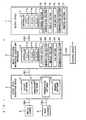
- Fig. 1 is a block diagram showing a construction of a printing system 1 according to a preferred embodiment of the present invention.
- the printing system 1 principally comprises a layout data generation device 2, an image processing information association processor 3, and an output device 7.
- the layout data generation device 2 is a device for generating layout data DL ( Fig. 4 ) serving as an original (referred to hereinafter as a printing original) of printed matter to be created, by using a photographic image, a graphic image, a CG image, or the like.
- the image processing information association processor 3 is a device for adding (or incorporating) image processing information (which will be described in detail later) to (or into) the layout data while associating the image processing information with RGB image data, the image processing information being image processing information relating to the process (an optimization process) of optimizing image data included in the layout data for printing.
- the optimization process used herein refers to a color space conversion process and an image correction process of the layout data including the RGB image data for the purpose of providing high-quality printed matter by printing based on the layout data.
- the output device 7 interprets the descriptions of the layout data (image processing equipped layout data) with predetermined image processing information added thereto to perform the optimization process described in the image processing information, and thereafter performs a rasterization process and a final output process.
- Data transfer between the layout data generation device 2 and the image processing information association processor 3 and between the image processing information association processor 3 and the output device 7 may be carried out either through communication lines CB1 and CB2 by constructing a network of these devices or through a portable
- the layout data generation device 2 is capable of acquiring photographic data obtained by image capturing using a digital camera 5 to use the photographic data for the layout of the printing original.
- the layout data generation device 2 may use image data acquired by an input device such as an image scanner 6 to do the layout.
- the image data transfer from the digital camera 5 and the image scanner 6 to the layout data generation device 2 is carried out either through connection cables CB3 and CB4 such as USB cables or by recording the image data on a portable recording medium (not shown) and reading the recorded image data in the layout data generation device 2.
- the layout data generation device 2 is implemented by a general-purpose personal computer.
- the layout data generation device 2 contains layout software 21, spreadsheet software 22, presentation software 23, drawing software 24 and the like which are installed therein.
- the layout data generation device 2 uses such software 21 to 24 to create and process an image as appropriate, and then generates the layout data serving as the printing original including the image, that is, the layout data DL with the image data incorporated therein.
- Commercially available software may be used as the software 21 to 24.
- the layout data DL is described on a page-by-page basis by a page description language (PDL).
- PDL page description language
- the layout data DL is described in the PDF.
- the image processing information association processor 3 is also implemented by a general-purpose personal computer.
- the image processing information association processor 3 principally comprises: a controller 31 including a CPU 31 a, a ROM 31 b and a RAM 31c for implementing functions to be described later; a storage section 32 constructed by a hard disk and the like for storing the layout data DL received from the outside of the processor 3, and a predetermined operating program 32p ( Fig.
- a manipulation section 33 including a mouse and a keyboard for an operator to enter various commands
- a display section 34 such as a display device
- an R/W section 35 for reading and writing data from and to various portable recording media
- a communication section 36 serving as an interface for transfer of data to and from other devices and the like.
- a so-called GUI Graphic User Interface
- a so-called GUI capable of processing while displaying the details of manipulation through the manipulation section 33 and the current processing status of various processes on the display section 34 is implemented by the functions of the controller 31, the manipulation section 33 and the display section 34. Processes in respective sections to be described later which are implemented in the controller 31 are also carried out using the GUI.
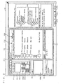
- Fig. 2 schematically shows a working window W displayed on the display section 34. The action of the GUI allows a desired process to be performed while the details of a command entered through the manipulation section 33 and the current status of operation are displayed in the working window W.
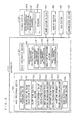
- Fig. 3 illustrates the functions implemented in the controller 31 of the image processing information association processor 3.
- Fig. 4 is a data flow diagram in the process of adding the image processing information.
- a data input/output section 40, an image processing section 50 and a image processing information processing section 60 in the controller 31 are implemented by the execution of the predetermined operating program 32p stored in the storage section 32 under the action of the CPU 31 a, the ROM 31b and the RAM 31 c.
- the data input/output section 40 is responsible for the process of reading one piece of layout data DL selected by an operator among one or more pieces of layout data DL stored in the storage section 32, and the process of storing image processing equipped layout data DLR subjected to a predetermined process to be described later in the storage section 32 so as to be able to send the image processing equipped layout data DLR to the output device 7.
- the image processing section 50 is principally responsible for the process of extracting image data DP incorporated in the layout data DL being processed to classify the image data DP.
- the image processing section 50 principally comprises an image extraction processing section 51, an image feature value calculation section 52, and an image classification processing section 53.
- the image extraction processing section 51 is responsible for the process (an image data extraction process) of analyzing the descriptions of the read layout data DL to extract the image data DP representing an RGB image.
- the layout data DL includes the descriptions of image data and text data, and layout information which are written in a predetermined page description language, for example in the PDF.
- the image extraction processing section 51 searches the layout data DL for a location which represents image data to extract the descriptions of the image data. It should be noted that a CMYK image represented in a CMYK color system may be previously extracted.
- the image feature value calculation section 52 is responsible for the process (an image feature value calculation process) of calculating an image feature value for identifying an image feature of an RGB image PC2 represented by the extracted image data DP, based on the descriptions of the extracted image data DP.
- the image feature value used herein is a generic term for values obtained (counted or calculated) for use in determining which feature the RGB image PC2 has and then classifying the RGB image PC2, which will be discussed later.
- the image feature value calculation section 52 includes a sharp peak counting section 52a, an edge component value calculation section 52b, a high saturation pixel ratio calculation section 52c, a specific color pixel ratio calculation section 52d, and an image line segment value calculation section 52e, each of which acquires a predetermined image feature value.
- the sharp peak counting section 52a is responsible for the process (a sharp peak counting process) of counting the number of sharper peaks (or taking a sharp peak count) than a predetermined limit in an RGB image represented by the image data DP.
- the sharp peak count refers to an image feature value indicative of the number of sharp peaks appearing in a histogram showing a distribution of the frequency of gradation levels for each color component of the RGB image.
- a high sharp peak count means that the image of interest has such an image feature that colors of specific gradation levels are largely outstanding. This implies that there is a high probability that the image of interest is an artificially created image such as a CG image and color-coded business graphics.
- the edge component value calculation section 52b is responsible for the process (an edge component value calculation process) of calculating an edge component value of each color component of the RGB image represented by the image data DP.
- the edge component value refers to an image feature value indicative of the proportion of the existing edges (or points at which a gradation level change occurs sharply) to the entire image.
- a high edge component value means that the image of interest has an image feature of being a sharp image having a clear boundary between regions of different color components. This implies that the image of interest has been subjected to a sharpness correction and that there is a high probability that there is no need to make the sharpness correction again thereto.
- the high saturation pixel ratio calculation section 52c is responsible for the process (a high saturation pixel ratio calculation process) of calculating a high saturation pixel ratio for the RGB image represented by the image data DP.
- the high saturation pixel ratio refers to an image feature value indicative of the proportion of pixels having a high saturation in the RGB image.
- the high saturation pixel ratio refers to the ratio of the area of a region occupied by the high-saturation pixels to the whole area occupied by the image.
- a large area of the region occupied by the high-saturation pixels in an image means that the image is a high-contrast image and is principally constructed by conspicuous color components. This implies that there is a high probability that the image is an artificially created image such as a CG image and color-coded business graphics.
- the specific color pixel ratio calculation section 52d is responsible for the process (a specific color pixel ratio calculation process) of calculating a specific color pixel ratio for the RGB image represented by the image data DP.
- the specific color pixel ratio refers to an image feature value indicative of the proportion of pixels having gradation levels falling within a specific range in the RGB image.
- the specific color pixel ratio refers to the ratio of the area of a region occupied by the pixels falling within a certain gradation level (color density) range to the whole area occupied by the image. For example, an inference that a person principally appears in the image will be derived from a large number of skin color components, and an inference that a landscape principally appears in the image will be derived from a large number of blue or green components.
- the image line segment value calculation section 52e is responsible for the process (an image line segment value calculation process) of calculating an image line segment value for the RGB image represented by the image data DP.
- the image line segment value refers to an image feature value indicative of the amount of line segments appearing in the RGB image. For example, an inference that an artificial object such as a machine, rather than a natural object such as a landscape, appears highly probably in the image will be derived from a large number of line segments drawn in the image.
- These sections of the image feature value calculation section 52 calculate the various image feature values, respectively, as discussed above, thereby to provide image feature value data DPC which is a dataset containing these image feature values. A method of calculating each of the image feature values will be described later in detail.
- the image classification processing section 53 is responsible for the process (an image classification process) of classifying RGB images represented by the image data DP incorporated in the layout data DL into some previously determined image categories in accordance with their image features.
- the image classification process is carried out by comparing the image feature value data DPC provided from the image feature value calculation section 52 with classification criterion data DCS previously determined for each image category.
- the image classification processing section 53 generates image classification data DC. This provides the classification of the plurality of RGB images arranged for the layout, based on the commonality of the features exhibited by the RGB images.
- the image classification data DC may be described, for example, in the form of (k,x,1) or (k,x,0) wherein the flag "1" is given when the k-th one of the pieces of image data DP incorporated in the layout data DL meets the x-th classification criterion described in the classification criterion data DCS; otherwise the flag "0" is given.
- Specific image categories are as follows. For example, when categorization (printing-suitability-based categorization) is made from the viewpoint of whether or not an image of sufficient quality is printed by the execution of only the color space conversion process from the RGB image to the CMYK image and the standard correction process, an ordinary image (natural image or unprocessed image) merely captured by a digital camera or read by a scanner and subjected to no corrections belongs to a "suitable" category.
- CG image and business graphics (a graph image, an image for presentation, and the like) in which specific color components are selectively used so that gradation levels exhibit a discrete distribution of frequency, an image subjected to the sharpness process, an image containing much noise, a blurred image such as an out-of-focus photograph, and the like belong to an "unsuitable" category in which it is judged that a special correction must be made to print an image of good quality.
- the classification criterion data DCS contains, for example, the following descriptions:
- the classification criterion data DCS contains, for example, the following descriptions:
- image processing information RI The generation and application of image processing information RI to be described below are based on the image categories each used as a unit. That is, a piece of image processing information RI is set, in principle, for each of the image categories.
- the image processing information processing section 60 is responsible for the process relating to the image processing information RI.
- the image processing information processing section 60 comprises a image processing information generation section 61, a image processing information application section 62, a simulation processing section 63, and a image processing information combination section 64.
- the image processing information generation section 61 is responsible for the process of generating the image processing information RI to store the image processing information RI in a image processing information database (DB) 32d provided in the storage section 32. As shown in Fig. 2 , the pieces of image processing information RI stored in the image processing information DB 32d are displayed together with respective image processing icons IC in a image processing information list box F3 of the working window W.
- DB image processing information database
- the image processing information RI refers to processing information about the details of the optimization process for printing to be performed in the output device 7 upon the image data DP incorporated in the layout data DL received as the original prior to the output process.
- the image processing information RI is described in the same description format as the layout data DL.
- the image processing information RI is also described in the PDF. If images arranged for the layout in the printing original belong to the same image category, it is considered that a color component desired to be enhanced and a consideration in color reproduction are common to the images. Therefore, the image processing information RI is preferably set for each of the image categories and previously entered in the image processing information DB 32d. Fig.
- the image processing information RI includes a color space conversion look-up table (LUT) RI1, a characteristic setting parameter RI2, and a fine adjustment parameter RI3.
- LUT color space conversion look-up table
- RI2 characteristic setting parameter
- RI3 fine adjustment parameter
- the color space conversion look-up table RI1 is set for reference during the color space conversion process for maintaining in the printed matter the color reproduction of the RGB images arranged for the layout in the printing original, the color space conversion process being included in the optimization process for printing. For example, a conversion from the original RGB color space to a color space represented based on Japan Color 2001 is set.
- the characteristic setting parameter RI2 is a setting parameter which determines the specific details of the image correction process to be performed on the image data DP, the image correction process being included in the optimization process for printing.
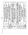
- Fig. 6 shows a setting item table TBL1 including a list of setting items of the characteristic setting parameter RI2.
- the specific settings for the respective items of the characteristic setting parameter RI2 shown in Fig. 6 are appropriately made in accordance with the features of the images belonging to each image category.
- a gradation level setting P1 is an item for setting the density range of halftone dots.
- a tone curve setting P2 is an item for setting a mid-tone or a half tone by means of a tone curve.
- a color correction setting P3 is an item for correcting a deviation from an ideal color characteristic of an ink.
- a K-plate setting P4 is an item for setting UCR (under color removal), GCR (gray component replacement) and the like for replacing an overlap between CMY colors with a K plate.
- a gray balance setting P5 is an item for setting a balance between CMY colors for proper gray representation.
- a sharpness setting P6 is an item for enhancing the sharpness of an image by the use of USM (unsharp masking) or the like.
- a resolution setting P7 is an item for converting the resolution of an image in an pixel interpolation process or the like.
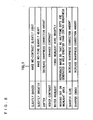
- Fig. 7 shows a corresponding relationship between image categories determined based on a certain piece of classification criterion data DCS and the details of the image correction process to be performed, prior to printing, upon images belonging to the respective image categories in the form of a correction detail table TBL2 by way of illustration.
- the characteristic setting parameter RI2 of the image processing information RI is set so that the details of the correction process shown in Fig. 7 are implemented on the images belonging to the respective image categories.
- FIG. 2 when an operator selects one of the plurality of pieces of image processing information RI listed in the image processing information list box F3 of the working window W, the detail of the corresponding correction process in the correction detail table TBL2 is displayed in a image processing information detail display box F4.
- "machine" image processing information is shown as selected.
- the output device 7 When the color space conversion look-up table RI1 and the characteristic setting parameter RI2 of the image processing information RI are appropriately set, the output device 7 performs the optimization process on the image data in accordance with the descriptions of the image processing information RI and thereafter performs the output process. If the printing original is received in the form of the RGB original, the execution of such an optimization process provides the output of printed matter of good quality.
- the fine adjustment parameter RI3 is a parameter to be set for operator's further addition of a fine adjustment to each item of the characteristic setting parameter RI2. Since a piece of image processing information RI is set, in principle, for each of the image categories as described above, it is considered appropriate to perform the same optimization process on the image data DP about images belonging to the same image category. However, because images belonging to the same image category slightly differ from each other in what they express, the uniform execution of the optimization process using the same piece of image processing information RI is not always an actually "optimum" process for the images. For use in such a case, the fine adjustment parameter RI3 is a parameter corresponding to an amount by which a default setting of the characteristic setting parameter RI2 is changed for manual fine adjustment to achieve a truly "optimum" process.
- a preferable form of the actual execution of the fine adjustment is to set the fine adjustment parameter RI3 in accordance with a processing menu of typical details of adjustment previously prepared.
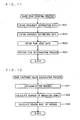
- Fig. 8 shows a fine adjustment menu table TBL3 including a typical processing menu for setting of the fine adjustment parameter RI3 in list form.
- the image processing information application section 62 is responsible for a process (a image processing information association process) in which the operator associates the image processing information RI with the image data DP incorporated in the layout data DL.
- the image processing information application section 62 is also responsible for the process of modifying the image processing information once associated, and the like.
- the image processing information association process refers to the process of associating a piece of image processing information RI suitable for each piece of image data DP incorporated in the layout data DL with the layout data DL.
- the image processing information application section 62 generates temporary data DT in which the applied piece of image processing information RI is associated with the layout data DL or the image data DP incorporated in the layout data DL. That is, the generation of the temporary data DT is the essential process of the image processing information association process.
- the temporary data DT may be generated by directly appending the image processing information RI to the layout data DL in a manner similar to the action to be achieved in the image processing information combination section 64 to be described later or by giving association information to the layout data DL or the image processing information RI to generate a dataset comprised of both thereof.
- the temporary data DT is used for an image simulation process in the simulation processing section 63 to be described later.
- the operator may click a delete button BT2 to erase all of the associated pieces of image processing information and then reexecute the image processing information association process under the action of the image processing information application section 62.
- the simulation processing section 63 is responsible for the process (a simulation process) of simulating, in the working window W, the optimization process for printing to be performed in the output device 7 upon the image data DP incorporated in the layout data DL based on the temporary data DT. Further, the operator may click a print button BT3 to cause a proofing device 4 such as a color ink jet printer connected, for example, through a connection cable CB5 to perform proof printing based on the temporary data DT.
- a proofing device 4 such as a color ink jet printer connected, for example, through a connection cable CB5 to perform proof printing based on the temporary data DT.
- the image processing information combination section 64 is responsible for the process (a image processing information addition process) of combining or adding fixed image processing information RIF with or to the layout data DL, the fixed image processing information RIF being the image processing information RI obtained when the operator judges that the image processing information RI is appropriately set as a result of the above-mentioned simulation process and the like.
- the image processing information combination section 64 generates the image processing equipped layout data DLR which is the layout data DL with the image processing information RI added thereto.
- the image processing equipped layout data DLR thus obtained is stored in the storage section 32 so as to be sendable to the output device 7.
- the image processing equipped layout data DLR is transferred to the output device 7 as appropriate, and is subjected to a predetermined process.
- the output device 7 is a device for performing a predetermined process on the layout data received from the image processing information association processor 3 to output printed matter. Prior to the output process, the output device 7 according to this preferred embodiment performs the optimization process for printing based on the descriptions of the fixed image processing information RIF, that is, the color space conversion process and image correction process optimum for what individual images express.
- the output device 7 comprises: a controller 71 including a CPU 71a, a ROM 71b and a RAM 71 c for implementing functions to be described later; a storage section 72; a manipulation section 73; a display section 74; an R/W section 75; a communication section 76, and the like, the functions of which are implemented by a computer.
- the output device 7 further comprises a printing section 77 for printing on a predetermined printing sheet.
- Fig. 9 illustrates the functions implemented in the controller 71 of the output device 7.
- An image conversion processing section 81, a rasterizing processing section 82 and a printing control section 83 in the controller 71 are implemented by the execution of a predetermined program 72p stored in the storage section 72 under the action of the CPU 71 a, the ROM 7 1 b and the RAM 71 c.
- the image conversion processing section 81 is provided for performing the optimization process on the image data DP contained in the image processing equipped layout data DLR received from the image processing information association processor 3, in accordance with the descriptions of the image processing information RI added to the image processing equipped layout data DLR by the image processing information association processor 3.
- the image conversion processing section 81 principally comprises a layout data analysis section 81a, a color space conversion section 81b, a color tone correction section 81c, a sharpness correction section 81 d, and a resolution conversion section 8 1e.
- the layout data analysis section 81 a analyzes the descriptions of the image processing equipped layout data DLR to extract the image processing information RI incorporated in the equipped layout data DLR and the image data DP to be subjected to the optimization process based on the image processing information RI.
- the color space conversion section 81b performs a CMYK conversion process on the image data DP in accordance with the color space conversion look-up table RI1 described in the image processing information RI.
- the color tone correction section 81c performs a density level correction and a tone curve correction on the CMYK-converted image data in accordance with the descriptions of the characteristic setting parameter RI2 and the fine adjustment parameter RI3 of the image processing information RI.
- the sharpness correction section 81 d performs an USM correction in accordance with the descriptions of the image processing information RI.
- the resolution conversion section 81e converts the resolution of an image in accordance with the descriptions of the image processing information RI.
- the image processing equipped layout data DLR (referred to hereinafter as optimized layout data) in which all of the pieces of image data DP incorporated therein are subjected to the processes in these sections is temporarily stored in the storage section 72, and is then provided to the rasterizing processing section 82.
- the rasterizing processing section 82 is provided for rasterizing (or performs the RIP or rasterization process on) the optimized layout data to provide raster data processable in the printing section 77 and corresponding to the plates of respective CMYK colors.
- a known technique may be used as the rasterizing process technique.
- the printing control section 83 is provided for controlling the execution of printing in the printing section 77.
- the printing section 77 performs printing on a predetermined printing sheet, based on the data for the plates of respective colors obtained by the rasterizing process.
- the output device 7 is responsible for both of the rasterizing process and the printing process in this preferred embodiment, the rasterizing process and the printing process may be performed by separate devices, respectively.
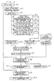
- Fig. 10 is a flow diagram for illustrating the process of adding the image processing information Rl to the layout data DL.
- the process of adding the image processing information RI starts with the process of reading the layout data DL to be processed under the action of the data input/output section 40 (in Step S1).
- a page layout image PL1 is displayed (on a reduced scale) in a layout image display box F1 of the working window W, as shown in Fig. 2 .
- the layout data DL to be processed is described in the PDF, has a file name "leaflet.pdf" and represents a printing original with a total of five pages, and the third page thereof is shown as displayed as the page layout image PL1. It is assumed that the third page has four RGB images PC1 to PC4 arranged thereon.
- the image data extraction process is performed under the action of the image extraction processing section 51 (in Step S2).
- the pieces of image data DP corresponding to the respective RGB images PC1 to PC4 are extracted and temporarily held in the RAM 31c.
- corresponding thumbnail images PS1 to PS4 are displayed in list form in an image display column F21 of a image processing application box F2 of the working window W.
- the image feature value calculation process performed in this step includes the sharp peak counting process under the action of the sharp peak counting section 52a, the edge component value calculation process under the action of the edge component value calculation section 52b, the high saturation pixel ratio calculation process under the action of the high saturation pixel ratio calculation section 52c, the specific color pixel ratio calculation process under the action of the specific color pixel ratio calculation section 52d, and the image line segment value calculation process under the action of the image line segment value calculation section 52e.
- Fig. 11 is a flow diagram of the sharp peak counting process for counting the number of sharper peaks than a predetermined limit.
- the image data DP represents an image composed of m x n pixels each containing R (red), G (green) and B (blue) color components with a 256-level gradation for representation of an 8-bit image.
- the gradation levels of a pixel (i,j) (where i and j are positive integers) in the image data DP are expressed as (R(i,j), G(ij), B(i,j)) (where 0 ⁇ R(ij), G(ij), B(ij) ⁇ 255; and R(i,j), G(i,j), B(i,j) are positive integers).
- an averaging process for averaging the frequencies of adjacent gradation levels, based on the obtained frequency distribution data is performed to provide averaged distribution data (in Step S22).
- the averaging process is carried out, for example, by averaging the frequencies of gradation levels lying within an averaging range Rp with respect to each gradation level.
- Rp 3
- a peak index calculation process is performed based on the averaged distribution data to calculate peak index data for use in a peak determination process for determining whether or not each of the gradation levels is at a peak position in the frequency distribution histogram (in Step S23).
- the peak determination process is performed using the calculated peak index data (in Step S24).
- a determination is made as to whether or not a peak index is greater than a peak threshold value Tp previously determined as a criterion of determination as to whether or not a peak is sharper than the predetermined limit.
- a determination is made as to whether or not Hbp c L > Tp is satisfied for all of values of c and L.
- Fig. 12 is a flow diagram of the edge component value calculation process.
- a calculation process (or a Laplacian filter process) for applying a 3 ⁇ 3 Laplacian filter FT1 shown in Fig. 15 to the gradation levels of the respective pixels is performed for each color component (in Step S31).
- Rf(i,j) -256 if Rf(i,j) ⁇ -256.
- Step S32 the average of the absolute values of the gradation levels obtained by the Laplacian filter process for all of the pixels is calculated for each color component (in Step S32). Adding the resultant averages for all of the color components together provides an average edge value.
- the square root of the average edge value is then calculated (in Step S33).
- an edge component value for each of the color components may be calculated by calculating the square root for each of the color components as expressed in Equation (6), rather than adding the averages for all of the color components together in Equation (5).
- Fig. 13 is a flow diagram of the high saturation pixel ratio calculation process.
- the saturations of the respective pixels are calculated (in Step S41).
- the high saturation pixel ratio is calculated using the obtained frequency distribution data (in Step S43).
- the specific color pixel ratio calculation process the number of specific color pixels is counted (or a specific color pixel count is taken), and the specific color pixel ratio is obtained as the ratio of the number of specific color pixels to the total number of pixels mn.
- the specific color pixel count Nr, for example, for the R color component is the number of pixels which meet one of the following three conditions:
- Fig. 14 is a flow diagram of the image line segment value calculation process.
- the following four line segment values are first calculated: a vertical line segment value, a horizontal line segment value, a first inclined line segment value (about a line segment slanting upwardly and rightwardly), and a second inclined line segment value (about a line segment slanting upwardly and leftwardly).
- a filter calculation process (or a vertical line segment filter process) for applying a 3 x 3 vertical line segment extraction filter FT2 shown in Fig. 16A to the gradation levels of the respective pixels is performed for each color component (in Step S51).
- the average of the gradation levels RI(ij) obtained by the vertical line segment filter process for all of the pixels is calculated for each color component (in Step S52). Adding the resultant averages for all of the color components together provides the vertical line segment value.
- Similar filter calculation processes are performed by applying a horizontal line segment extraction filter FT3 shown in Fig. 16B , a first inclined line segment extraction filter FT4 shown in Fig.
- the sections of the image feature value calculation section 52 calculate the various image feature values, respectively, as discussed above, thereby to provide the image feature value data DPC which is a dataset containing these image feature values.
- the image feature value data DPC about the k-th one of the pieces of image data DP incorporated in the layout data DL is described, for example, in the form of (k,Np,Lav,Dc,Dr,Lpav).
- the method of calculating the image feature values and the description format as described hereinabove are only illustrative, but may be modified in other forms.
- the image classification process is performed on all of the pieces of image data DP incorporated in the layout data DL under the action of the image classification processing section 53 (in Step S4).
- the image classification data DC is generated by the image classification process
- all of the image categories to which the RGB images contained in the printing original belong are displayed in list form in an image category list box F5 of the working window W, as shown in Fig. 2 .
- the image categories into which the individual RGB images PC1 to PC4 are classified are displayed in corresponding relation to the respective thumbnail images PS1 to PS4 in an image category display column F22 of the image processing application box F2 of the working window W.
- the thumbnail images PS1 to PS4 may be displayed for each image category, based on the image classification data DC.
- the operator may select a specific image category in the image category list box F5 to cause only the thumbnail images of the RGB images belonging to the specific category to be displayed.
- thumbnail images of the CMYK images incorporated in the layout data DL may be additionally displayed in the image processing application box F2. It is assumed that a thumbnail image PS5 illustrates such a CMYK image in Fig. 2 .
- Step S5 the operator then performs the image processing information association process (in Step S5).
- the manipulation by the operator is made in the working window W shown in Fig. 2 .
- all of the image categories to which the RGB images contained in the printing original belong are displayed in list form in the image category list box F5.
- the operator drags and drops (D&D) the image processing icon IC of a piece of image processing information RI desired to be applied to a certain image category (i.e., an image belonging to the certain image category) into the position of the certain image category in the image category list box F5 of the working window W.
- the image processing information application section 62 In response to the selection by the drag-and-drop operation, the image processing information application section 62 generates the temporary data DT in which the piece of image processing information RI applied by the above-mentioned drag-and-drop operation is associated with one or more pieces of image data about one or more RGB images belonging to the image category of interest among all of the pieces of image data DP incorporated in the layout data DL. This results in the simultaneous application of the same piece of image processing information RI to all of the images belonging to the same image category, thereby to reduce the complexity of processing even if a multiplicity of images are arranged for the layout.
- the temporary data DT may be generated by directly appending the image processing information RI to the layout data DL in a manner similar to the action of the image processing information combination section 64 to be described later or by giving association information indicative of the association between the layout data DL and the image processing information RI to either the layout data DL or the image processing information RI while the layout data DL and the image processing information RI are held separate.
- a display indicative of the applied piece of image processing information RI is produced in a location corresponding to each image belonging to the corresponding category in a set image processing display column F23 of the image processing application box F2 of the working window W.
- This enables the operator to visually recognize how the association is established.
- a piece of image processing information RI designated as "Landscape + Machine” is shown as set for the "landscape” category
- a piece of image processing information RI designated as "Machine” is shown as set for the "machine” category
- a piece of image processing information RI designated as "Standard” is shown as set for the "suitable” category.
- the application of the image processing information RI on an image-by-image basis may be carried out by dragging and dropping image processing icon IC into an RGB image displayed in the layout image display box F1 or into a thumbnail image displayed in the image processing application box F2.
- Step S6 After the image processing information RI is applied to the image data DP, a simulation process is performed to judge whether or not the application is appropriate (in Step S6).
- the operator selects one of the thumbnail images PS1 to PS4 displayed in the image processing application box F2 and subjected to the application of the image processing information RI.
- the simulation processing section 63 displays in a simulation image display box F6 a simulation image PSM obtained by simulating an image to be outputted after the optimization process in accordance with the image processing information RI by the output device 7 while referring to the descriptions of the piece of image data DP corresponding to the selected thumbnail image and the piece of image processing information RI associated with the piece of image data DP among the descriptions of the temporary data DT.
- This enables the operator to consider whether or not the application of the piece of image processing information RI is appropriate, based on the simulation image PSM.
- the simulation process is shown as performed on the RGB image PC2.
- Step S7 When the operator that views the simulation image PSM judges that the setting of the piece of image processing information RI is not appropriate (NO in Step S7), the operator can enter a command by clicking a image processing information fine adjustment button BT1, thereby to make a fine adjustment to the associated piece of image processing information RI (in Step S8). Clicking the image processing information fine adjustment button BT1 produces a display of predetermined items of the fine adjustment menu, for example, as shown in Fig. 8 in a fine adjustment setting box F7.
- a parameter of the associated piece of image processing information RI is adjusted under the action of the image processing information application section 62, whereby the temporary data DT is rewritten by the modification of the associated piece of image processing information RI.
- the simulation process may be performed again based on the rewritten temporary data DT.
- Step S9 When the operator judges that the image processing information RI applied to all of the images is appropriate and clicks an OK button BT4, the applied image processing information RI is fixed to provide the fixed image processing information RIF at this point of time (in Step S9).
- the operator clicks a cancel button BT5 the image processing information addition process is completely cancelled.
- the image processing information combination section 64 performs the image processing information addition process (in Step S10).
- the image processing information addition process is achieved by appending the fixed image processing information RIF to the layout data DL.
- Appending the image processing information RI to the layout data DL provides the image processing equipped layout data DLR.
- an RGB image and a piece of fixed image processing information RIF corresponding thereto are paired with each other in the descriptions of the image processing equipped layout data DLR.
- the fixed image processing information RIF corresponding to an image present on a certain page is at least described on the page.
- the image processing equipped layout data DLR thus obtained is transferred to the output device 7.
- the optimization process for printing based on the descriptions of the fixed image processing information RIF, that is, the color space conversion process and image correction process optimum for what individual images express are performed on the individual images, prior to the output process, under the action of the sections constituting the image conversion processing section 81 implemented in the controller 71. Thereafter, the rasterizing process of the rasterizing processing section 82 and the printing process are executed.
- the present invention achieves the addition to the layout data, of the image processing information necessary for the output device to perform the process (or the optimization process) of optimizing RGB image data contained in the layout data for printing while associating the image processing information with the respective image data, based on the image features of the image data.
- This enables the output device to output good-quality printed matter excellent in color reproduction and the like if information for the process of optimizing the RGB image data is not previously provided during the generation of the layout data.
- the plurality of RGB images arranged for the layout are classified based on the commonality of the features exhibited by the RGB images, and the same piece of image processing information is applied to RGB images belonging to the same image category at the same time. This reduces the complexity of processing even if a multiplicity of images are arranged for the layout.
- the simulation can be done to judge whether or not the optimization process based on the applied piece of image processing information is appropriate, and the applied piece of image processing information is fine-adjustable. This allows the application of a piece of image processing information most suitable for what the individual images express, and the provision of the most suitable piece of image processing information to the optimization process in the output device.
- the image processing information association processor may be provided in the output process step responsible for the output process to make a check of the layout data received as the original prior to the output process.
- the image processing information association processor may be provided in a design/production process step for generating the layout data, in which case the image processing information association processor is used during the receipt of the layout data as the original to suitably perform image processing, and thereafter transfers the original to the output process step.
- the latter also makes a kind of preflight check of the layout data.
- the image processing information association processor may be constructed, for example, integrally with the output device.
- the image processing information association processor may be constructed, for example, integrally with the layout data generation device.
Abstract
Description
- The present invention relates to a technique for a conversion process for optimizing RGB image data for printing in a printing system for commercial printing.
- The proliferation of digital cameras has increased the so-called submission of RGB originals, that is, the transfer (or submission) of layout data for use as an original for printing to a prepress/printing process step, the layout data being created using a photographic image which is an image (RGB image) captured by a digital camera and represented in the RGB color system. RGB image data which provides an RGB image is incorporated (or described) in accordance with a predetermined format in layout data submitted in the form of an RGB original. In the prepress/printing process step, however, it is necessary to perform a color space conversion process for converting the RGB image data into CMYK image data which provides a printable image (CMYK image) represented in the CMYK color system.
- Graphic images including graphs created using spreadsheet software or presentation software and so-called CG (computer graphics) images created using drawing software are also created in the form of RGB images. The submission of RGB originals as originals for printing in which such graphic and CG images are arranged in the form of the RGB images for layout has also been on the increase.
- The layout data is created, for example, as PDF (Portable Document Format) data. When the layout data is described in the PDF, the color space conversion process is performed on all images arranged for layout by one operation, based on an ICC profile embedded as header information in the layout data.
- However, the ICC profile is originally used to maintain color reproduction between input/output devices having different color reproduction characteristics, and the color space conversion process based on the ICC profile is performed uniformly on all image data incorporated in the layout data. Thus, the color space conversion process neither reflects conventional conversion processes (gamut mapping) which have been done by a scanner operator based on his/her empirical rules, nor carries out an sharpness process. On the other hand, it is a common practice that a plurality of images are arranged for layout on printed matter. Individual images different in type (photographic, graphic, or CG images) and in what they express necessitate different processes of image correction to be performed for improvements in expressiveness thereof. To achieve high-quality printed matter, there arises a need to individually perform such image correction processes on a plurality of pieces of image data which provide the individual images in the prepress/printing process step.
- To satisfy the need, a printing system (RGB image quality control system) to be described below has been accomplished. In this printing system image processing (recipe) data, indicative of the details of the color space conversion process and the image correction process which are image processing to be performed on each RGB image in the prepress/printing process step, is incorporated (or described) during a layout operation in a production/design process step into the layout data described in the PDF and including photographic data providing the RGB images. Then, in the prepress/printing process step, the printing system interprets the details of the image processing data to perform a necessary process, and thereafter performs a rasterizing process or other processes.
- If only the image conversion process based on the ICC profile is performed on the layout data received in the form of the RGB original, it is necessary to perform the above-mentioned image correction process on the individual pieces of RGB image data incorporated in the layout data in the prepress/printing process step. However, an output process has become more automated in the recent prepress/printing process, as represented by an intelligence workflow RIP system, and the setting of parameters regarding the output process has become a main operation in the prepress/printing process step. Thus, the above-mentioned correction process is incompatible with the more automated output process.
- There is another problem to be described below. Not only the conversion process from the RGB image data to the CMYK image data but also the image correction process to be performed on the original for printing for the purpose of providing high-quality printing has conventionally been performed in a quite different process step than the prepress/printing process step. Therefore, there are not a sufficient number of operators skilled in such processes in the prepress/printing process step.
- The use of the above-mentioned RGB image quality control system solves the aforementioned problems in the prepress/printing process step. However, in the RGB image quality control system, equipment for the production/design process step which is a sender of the layout data must have special software capable of creating the image processing data prior to the layout of printed matter. The layout data subjected to such a special process are not always created in the production/design process step.
- The present invention is intended for a technique for a conversion process for optimizing RGB image data for printing in a printing system for commercial printing. According to the present invention, a printing system comprises: a) an image processing information association processor for performing an association process, the association process being the process of associating image processing information necessary for a predetermined output device to perform predetermined image processing with each of one or more pieces of RGB image data contained in layout data described by a page description language, the image processing information association processor including a-1) an image processing information storage element for storing therein a plurality of pieces of image processing information different in detail of processing from each other, a-2) a layout data reading element for reading layout data containing one or more pieces of RGB image data, a-3) an image data extraction element for extracting the one or more pieces of RGB image data from the layout data by searching the descriptions with respect to said RGB image data in said layout data a-4) an image feature value calculation element for calculating at least one image feature value for each of the one or more pieces of RGB image data extracted, a-5) an image classification element for making a comparison between the at least one image feature value and a predetermined classification criterion to classify the one or more pieces of RGB image extracted data into a plurality of image categories in accordance with a result of the comparison, the plurality of image categories being previously determined in accordance with the classification criterion, a-6) an association processing element for associating a selected one of the plurality of pieces of image processing information with each of the one or more pieces of RGB image data, and a-7) a combination element for combining the associated one of the plurality of pieces of image processing information with the layout data; thus forming process information equipped layout data; and b) an output device including b-1) an image processing element for performing the predetermined image processing on each of the one or more pieces of RGB image data contained in the layout data, based on the associated one of the plurality of pieces of image processing information, the predetermined image processing being the process of converting each of the one or more pieces of RGB image data into a piece of image data capable of being subjected to an output process, and b-2) an output processing element for performing the output process, based on layout data containing the one or more pieces of RGB image data subjected to the predetermined image processing.
- This enables the output device to perform the image processing for converting the RGB image data into the image data capable of being subjected to the output process by reference to the image processing information combined with the layout data, thereby outputting good-quality printed matter excellent in color reproduction and the like if information for the process of optimizing the RGB image data is not previously provided during the generation of the layout data.
-
EP-A-286 414 - It is therefore an object of the present invention to provide an image processing information association processor for associating image processing information for optimization of RGB image data for printing with the RGB image data in layout data when the layout data prepared as an original for printing contains the RGB image data, and a printing system including the image processing information association processor.
- These and other objects, features, aspects and advantages of the present invention will become more apparent from the following detailed description of the present invention when taken in conjunction with the accompanying drawings.
-
-
Fig. 1 is a block diagram showing a construction of a printing system according to a preferred embodiment of the present invention; -
Fig. 2 schematically shows a working window displayed on a display section of an image processing information association processor; -
Fig. 3 illustrates functions implemented in a controller of the image processing information association processor; -
Fig. 4 is a data flow diagram in the process of adding image processing information; -
Fig. 5 schematically shows a structure of the image processing information; -
Fig. 6 shows a setting item table including a list of setting items of a characteristic setting parameter; -
Fig. 7 shows a corresponding relationship between image categories and the details of an image correction process to be performed on images belonging to the image categories in the form of a correction detail table by way of illustration; -
Fig. 8 shows a fine adjustment menu table including a typical processing menu for setting of a fine adjustment parameter in list form; -
Fig. 9 illustrates functions implemented in a controller of an output device; -
Fig. 10 is a flow diagram for illustrating the process of adding the image processing information to layout data; -
Fig. 11 is a process flow diagram in a sharp peak counting section; -
Fig. 12 is a process flow diagram in an edge component value calculation section; -
Fig. 13 is a process flow diagram in a high saturation pixel ratio calculation section; -
Fig. 14 is a process flow diagram in an image line segment value calculation section; -
Fig. 15 shows a Laplacian filter; and -
Figs. 16A to 16D show calculation process filters. -
Fig. 1 is a block diagram showing a construction of aprinting system 1 according to a preferred embodiment of the present invention. Theprinting system 1 principally comprises a layoutdata generation device 2, an image processinginformation association processor 3, and an output device 7. The layoutdata generation device 2 is a device for generating layout data DL (Fig. 4 ) serving as an original (referred to hereinafter as a printing original) of printed matter to be created, by using a photographic image, a graphic image, a CG image, or the like. The image processinginformation association processor 3 is a device for adding (or incorporating) image processing information (which will be described in detail later) to (or into) the layout data while associating the image processing information with RGB image data, the image processing information being image processing information relating to the process (an optimization process) of optimizing image data included in the layout data for printing. The optimization process used herein refers to a color space conversion process and an image correction process of the layout data including the RGB image data for the purpose of providing high-quality printed matter by printing based on the layout data. The output device 7 interprets the descriptions of the layout data (image processing equipped layout data) with predetermined image processing information added thereto to perform the optimization process described in the image processing information, and thereafter performs a rasterization process and a final output process. Data transfer between the layoutdata generation device 2 and the image processinginformation association processor 3 and between the image processinginformation association processor 3 and the output device 7 may be carried out either through communication lines CB1 and CB2 by constructing a network of these devices or through a portable recording medium. - The layout
data generation device 2 is capable of acquiring photographic data obtained by image capturing using adigital camera 5 to use the photographic data for the layout of the printing original. Alternatively, the layoutdata generation device 2 may use image data acquired by an input device such as animage scanner 6 to do the layout. The image data transfer from thedigital camera 5 and theimage scanner 6 to the layoutdata generation device 2 is carried out either through connection cables CB3 and CB4 such as USB cables or by recording the image data on a portable recording medium (not shown) and reading the recorded image data in the layoutdata generation device 2. - The layout
data generation device 2 is implemented by a general-purpose personal computer. The layoutdata generation device 2 containslayout software 21,spreadsheet software 22,presentation software 23,drawing software 24 and the like which are installed therein. The layoutdata generation device 2 usessuch software 21 to 24 to create and process an image as appropriate, and then generates the layout data serving as the printing original including the image, that is, the layout data DL with the image data incorporated therein. Commercially available software may be used as thesoftware 21 to 24. The layout data DL is described on a page-by-page basis by a page description language (PDL). Preferably, the layout data DL is described in the PDF. - The image processing
information association processor 3 is also implemented by a general-purpose personal computer. The image processinginformation association processor 3 principally comprises: acontroller 31 including aCPU 31 a, aROM 31 b and aRAM 31c for implementing functions to be described later; astorage section 32 constructed by a hard disk and the like for storing the layout data DL received from the outside of theprocessor 3, and apredetermined operating program 32p (Fig. 3 ) for causing the personal computer to implement the image processinginformation association processor 3; amanipulation section 33 including a mouse and a keyboard for an operator to enter various commands; adisplay section 34 such as a display device; an R/W section 35 for reading and writing data from and to various portable recording media; and acommunication section 36 serving as an interface for transfer of data to and from other devices and the like. - In the image processing
information association processor 3, a so-called GUI (Graphical User Interface) capable of processing while displaying the details of manipulation through themanipulation section 33 and the current processing status of various processes on thedisplay section 34 is implemented by the functions of thecontroller 31, themanipulation section 33 and thedisplay section 34. Processes in respective sections to be described later which are implemented in thecontroller 31 are also carried out using the GUI.Fig. 2 schematically shows a working window W displayed on thedisplay section 34. The action of the GUI allows a desired process to be performed while the details of a command entered through themanipulation section 33 and the current status of operation are displayed in the working window W. -
Fig. 3 illustrates the functions implemented in thecontroller 31 of the image processinginformation association processor 3.Fig. 4 is a data flow diagram in the process of adding the image processing information. - A data input/
output section 40, animage processing section 50 and a image processinginformation processing section 60 in thecontroller 31 are implemented by the execution of thepredetermined operating program 32p stored in thestorage section 32 under the action of theCPU 31 a, theROM 31b and theRAM 31 c. - The data input/
output section 40 is responsible for the process of reading one piece of layout data DL selected by an operator among one or more pieces of layout data DL stored in thestorage section 32, and the process of storing image processing equipped layout data DLR subjected to a predetermined process to be described later in thestorage section 32 so as to be able to send the image processing equipped layout data DLR to the output device 7. - The
image processing section 50 is principally responsible for the process of extracting image data DP incorporated in the layout data DL being processed to classify the image data DP. For this process, theimage processing section 50 principally comprises an imageextraction processing section 51, an image featurevalue calculation section 52, and an imageclassification processing section 53. - The image
extraction processing section 51 is responsible for the process (an image data extraction process) of analyzing the descriptions of the read layout data DL to extract the image data DP representing an RGB image. The layout data DL includes the descriptions of image data and text data, and layout information which are written in a predetermined page description language, for example in the PDF. The imageextraction processing section 51 searches the layout data DL for a location which represents image data to extract the descriptions of the image data. It should be noted that a CMYK image represented in a CMYK color system may be previously extracted. - The image feature
value calculation section 52 is responsible for the process (an image feature value calculation process) of calculating an image feature value for identifying an image feature of an RGB image PC2 represented by the extracted image data DP, based on the descriptions of the extracted image data DP. The image feature value used herein is a generic term for values obtained (counted or calculated) for use in determining which feature the RGB image PC2 has and then classifying the RGB image PC2, which will be discussed later. The image featurevalue calculation section 52 includes a sharppeak counting section 52a, an edge componentvalue calculation section 52b, a high saturation pixelratio calculation section 52c, a specific color pixelratio calculation section 52d, and an image line segmentvalue calculation section 52e, each of which acquires a predetermined image feature value. - The sharp
peak counting section 52a is responsible for the process (a sharp peak counting process) of counting the number of sharper peaks (or taking a sharp peak count) than a predetermined limit in an RGB image represented by the image data DP. The sharp peak count refers to an image feature value indicative of the number of sharp peaks appearing in a histogram showing a distribution of the frequency of gradation levels for each color component of the RGB image. A high sharp peak count means that the image of interest has such an image feature that colors of specific gradation levels are largely outstanding. This implies that there is a high probability that the image of interest is an artificially created image such as a CG image and color-coded business graphics. - The edge component
value calculation section 52b is responsible for the process (an edge component value calculation process) of calculating an edge component value of each color component of the RGB image represented by the image data DP. The edge component value refers to an image feature value indicative of the proportion of the existing edges (or points at which a gradation level change occurs sharply) to the entire image. A high edge component value means that the image of interest has an image feature of being a sharp image having a clear boundary between regions of different color components. This implies that the image of interest has been subjected to a sharpness correction and that there is a high probability that there is no need to make the sharpness correction again thereto. - The high saturation pixel
ratio calculation section 52c is responsible for the process (a high saturation pixel ratio calculation process) of calculating a high saturation pixel ratio for the RGB image represented by the image data DP. The high saturation pixel ratio refers to an image feature value indicative of the proportion of pixels having a high saturation in the RGB image. In other words, the high saturation pixel ratio refers to the ratio of the area of a region occupied by the high-saturation pixels to the whole area occupied by the image. A large area of the region occupied by the high-saturation pixels in an image means that the image is a high-contrast image and is principally constructed by conspicuous color components. This implies that there is a high probability that the image is an artificially created image such as a CG image and color-coded business graphics. - The specific color pixel
ratio calculation section 52d is responsible for the process (a specific color pixel ratio calculation process) of calculating a specific color pixel ratio for the RGB image represented by the image data DP. The specific color pixel ratio refers to an image feature value indicative of the proportion of pixels having gradation levels falling within a specific range in the RGB image. In other words, the specific color pixel ratio refers to the ratio of the area of a region occupied by the pixels falling within a certain gradation level (color density) range to the whole area occupied by the image. For example, an inference that a person principally appears in the image will be derived from a large number of skin color components, and an inference that a landscape principally appears in the image will be derived from a large number of blue or green components. - The image line segment
value calculation section 52e is responsible for the process (an image line segment value calculation process) of calculating an image line segment value for the RGB image represented by the image data DP. The image line segment value refers to an image feature value indicative of the amount of line segments appearing in the RGB image. For example, an inference that an artificial object such as a machine, rather than a natural object such as a landscape, appears highly probably in the image will be derived from a large number of line segments drawn in the image. - These sections of the image feature
value calculation section 52 calculate the various image feature values, respectively, as discussed above, thereby to provide image feature value data DPC which is a dataset containing these image feature values. A method of calculating each of the image feature values will be described later in detail. - The image
classification processing section 53 is responsible for the process (an image classification process) of classifying RGB images represented by the image data DP incorporated in the layout data DL into some previously determined image categories in accordance with their image features. The image classification process is carried out by comparing the image feature value data DPC provided from the image featurevalue calculation section 52 with classification criterion data DCS previously determined for each image category. As a result of the image classification process, the imageclassification processing section 53 generates image classification data DC. This provides the classification of the plurality of RGB images arranged for the layout, based on the commonality of the features exhibited by the RGB images. - The image classification data DC may be described, for example, in the form of (k,x,1) or (k,x,0) wherein the flag "1" is given when the k-th one of the pieces of image data DP incorporated in the layout data DL meets the x-th classification criterion described in the classification criterion data DCS; otherwise the flag "0" is given.
- Specific image categories are as follows. For example, when categorization (printing-suitability-based categorization) is made from the viewpoint of whether or not an image of sufficient quality is printed by the execution of only the color space conversion process from the RGB image to the CMYK image and the standard correction process, an ordinary image (natural image or unprocessed image) merely captured by a digital camera or read by a scanner and subjected to no corrections belongs to a "suitable" category. On the other hand, a CG image and business graphics (a graph image, an image for presentation, and the like) in which specific color components are selectively used so that gradation levels exhibit a discrete distribution of frequency, an image subjected to the sharpness process, an image containing much noise, a blurred image such as an out-of-focus photograph, and the like belong to an "unsuitable" category in which it is judged that a special correction must be made to print an image of good quality. In this case, the classification criterion data DCS contains, for example, the following descriptions:
- Unsuitable image if Np ≥ 4;
- No need for the sharpness process (or unsuitable image) if Lav ≥ 10;
- Suitable image (or ordinary image) if Dc = 0 ; unsuitable image if
Dc# 0. - When categorization (image-representation-based categorization) is made according to what images represent (or image representations), images are classified into the following categories: a "person" category, a "landscape" category, a "machine" category, and the like. In this case, the classification criterion data DCS contains, for example, the following descriptions:
- "Person" category if a skin color pixel ratio ≥ 0.8 ;
- "Landscape" category if a green pixel ratio ≥ 0.4 and a blue pixel ratio ≥ 0.4 ;
- "Machine" category if the image line segment value ≥ 0.7.
- The generation and application of image processing information RI to be described below are based on the image categories each used as a unit. That is, a piece of image processing information RI is set, in principle, for each of the image categories.
- The image processing
information processing section 60 is responsible for the process relating to the image processing information RI. For this purpose, the image processinginformation processing section 60 comprises a image processinginformation generation section 61, a image processinginformation application section 62, asimulation processing section 63, and a image processinginformation combination section 64. - The image processing
information generation section 61 is responsible for the process of generating the image processing information RI to store the image processing information RI in a image processing information database (DB) 32d provided in thestorage section 32. As shown inFig. 2 , the pieces of image processing information RI stored in the imageprocessing information DB 32d are displayed together with respective image processing icons IC in a image processing information list box F3 of the working window W. - The image processing information RI will be described. The image processing information RI refers to processing information about the details of the optimization process for printing to be performed in the output device 7 upon the image data DP incorporated in the layout data DL received as the original prior to the output process. The image processing information RI is described in the same description format as the layout data DL. Thus, when the layout data DL is described in the PDF, the image processing information RI is also described in the PDF. If images arranged for the layout in the printing original belong to the same image category, it is considered that a color component desired to be enhanced and a consideration in color reproduction are common to the images. Therefore, the image processing information RI is preferably set for each of the image categories and previously entered in the image
processing information DB 32d.Fig. 5 schematically shows a structure of the image processing information RI. As shown inFig. 5 , the image processing information RI includes a color space conversion look-up table (LUT) RI1, a characteristic setting parameter RI2, and a fine adjustment parameter RI3. - The color space conversion look-up table RI1 is set for reference during the color space conversion process for maintaining in the printed matter the color reproduction of the RGB images arranged for the layout in the printing original, the color space conversion process being included in the optimization process for printing. For example, a conversion from the original RGB color space to a color space represented based on Japan Color 2001 is set.
- The characteristic setting parameter RI2 is a setting parameter which determines the specific details of the image correction process to be performed on the image data DP, the image correction process being included in the optimization process for printing.
Fig. 6 shows a setting item table TBL1 including a list of setting items of the characteristic setting parameter RI2. The specific settings for the respective items of the characteristic setting parameter RI2 shown inFig. 6 are appropriately made in accordance with the features of the images belonging to each image category. - The items of the characteristic setting parameter RI2 will be described one by one. A gradation level setting P1 is an item for setting the density range of halftone dots. A tone curve setting P2 is an item for setting a mid-tone or a half tone by means of a tone curve. A color correction setting P3 is an item for correcting a deviation from an ideal color characteristic of an ink. A K-plate setting P4 is an item for setting UCR (under color removal), GCR (gray component replacement) and the like for replacing an overlap between CMY colors with a K plate. A gray balance setting P5 is an item for setting a balance between CMY colors for proper gray representation. A sharpness setting P6 is an item for enhancing the sharpness of an image by the use of USM (unsharp masking) or the like. A resolution setting P7 is an item for converting the resolution of an image in an pixel interpolation process or the like.
-
Fig. 7 shows a corresponding relationship between image categories determined based on a certain piece of classification criterion data DCS and the details of the image correction process to be performed, prior to printing, upon images belonging to the respective image categories in the form of a correction detail table TBL2 by way of illustration. The characteristic setting parameter RI2 of the image processing information RI is set so that the details of the correction process shown inFig. 7 are implemented on the images belonging to the respective image categories. As shown inFig. 2 , when an operator selects one of the plurality of pieces of image processing information RI listed in the image processing information list box F3 of the working window W, the detail of the corresponding correction process in the correction detail table TBL2 is displayed in a image processing information detail display box F4. InFig. 2 , "machine" image processing information is shown as selected. - When the color space conversion look-up table RI1 and the characteristic setting parameter RI2 of the image processing information RI are appropriately set, the output device 7 performs the optimization process on the image data in accordance with the descriptions of the image processing information RI and thereafter performs the output process. If the printing original is received in the form of the RGB original, the execution of such an optimization process provides the output of printed matter of good quality.
- The fine adjustment parameter RI3 is a parameter to be set for operator's further addition of a fine adjustment to each item of the characteristic setting parameter RI2. Since a piece of image processing information RI is set, in principle, for each of the image categories as described above, it is considered appropriate to perform the same optimization process on the image data DP about images belonging to the same image category. However, because images belonging to the same image category slightly differ from each other in what they express, the uniform execution of the optimization process using the same piece of image processing information RI is not always an actually "optimum" process for the images. For use in such a case, the fine adjustment parameter RI3 is a parameter corresponding to an amount by which a default setting of the characteristic setting parameter RI2 is changed for manual fine adjustment to achieve a truly "optimum" process. A preferable form of the actual execution of the fine adjustment is to set the fine adjustment parameter RI3 in accordance with a processing menu of typical details of adjustment previously prepared.
Fig. 8 shows a fine adjustment menu table TBL3 including a typical processing menu for setting of the fine adjustment parameter RI3 in list form. - Returning to the description of the image processing
information processing section 60, the image processinginformation application section 62 is responsible for a process (a image processing information association process) in which the operator associates the image processing information RI with the image data DP incorporated in the layout data DL. The image processinginformation application section 62 is also responsible for the process of modifying the image processing information once associated, and the like. The image processing information association process refers to the process of associating a piece of image processing information RI suitable for each piece of image data DP incorporated in the layout data DL with the layout data DL. - The image processing
information application section 62 generates temporary data DT in which the applied piece of image processing information RI is associated with the layout data DL or the image data DP incorporated in the layout data DL. That is, the generation of the temporary data DT is the essential process of the image processing information association process. The temporary data DT may be generated by directly appending the image processing information RI to the layout data DL in a manner similar to the action to be achieved in the image processinginformation combination section 64 to be described later or by giving association information to the layout data DL or the image processing information RI to generate a dataset comprised of both thereof. The temporary data DT is used for an image simulation process in thesimulation processing section 63 to be described later. The operator may click a delete button BT2 to erase all of the associated pieces of image processing information and then reexecute the image processing information association process under the action of the image processinginformation application section 62. - The
simulation processing section 63 is responsible for the process (a simulation process) of simulating, in the working window W, the optimization process for printing to be performed in the output device 7 upon the image data DP incorporated in the layout data DL based on the temporary data DT. Further, the operator may click a print button BT3 to cause aproofing device 4 such as a color ink jet printer connected, for example, through a connection cable CB5 to perform proof printing based on the temporary data DT. - The image processing
information combination section 64 is responsible for the process (a image processing information addition process) of combining or adding fixed image processing information RIF with or to the layout data DL, the fixed image processing information RIF being the image processing information RI obtained when the operator judges that the image processing information RI is appropriately set as a result of the above-mentioned simulation process and the like. Thus, the image processinginformation combination section 64 generates the image processing equipped layout data DLR which is the layout data DL with the image processing information RI added thereto. - The image processing equipped layout data DLR thus obtained is stored in the
storage section 32 so as to be sendable to the output device 7. The image processing equipped layout data DLR is transferred to the output device 7 as appropriate, and is subjected to a predetermined process. - The output device 7 is a device for performing a predetermined process on the layout data received from the image processing
information association processor 3 to output printed matter. Prior to the output process, the output device 7 according to this preferred embodiment performs the optimization process for printing based on the descriptions of the fixed image processing information RIF, that is, the color space conversion process and image correction process optimum for what individual images express. The output device 7 comprises: acontroller 71 including aCPU 71a, aROM 71b and aRAM 71 c for implementing functions to be described later; astorage section 72; amanipulation section 73; adisplay section 74; an R/W section 75; acommunication section 76, and the like, the functions of which are implemented by a computer. The output device 7 further comprises aprinting section 77 for printing on a predetermined printing sheet. -
Fig. 9 illustrates the functions implemented in thecontroller 71 of the output device 7. An imageconversion processing section 81, arasterizing processing section 82 and aprinting control section 83 in thecontroller 71 are implemented by the execution of a predetermined program 72p stored in thestorage section 72 under the action of theCPU 71 a, the ROM 7 1 b and theRAM 71 c. - The image
conversion processing section 81 is provided for performing the optimization process on the image data DP contained in the image processing equipped layout data DLR received from the image processinginformation association processor 3, in accordance with the descriptions of the image processing information RI added to the image processing equipped layout data DLR by the image processinginformation association processor 3. - To this end, the image
conversion processing section 81 principally comprises a layoutdata analysis section 81a, a colorspace conversion section 81b, a colortone correction section 81c, asharpness correction section 81 d, and a resolution conversion section 8 1e. - The layout
data analysis section 81 a analyzes the descriptions of the image processing equipped layout data DLR to extract the image processing information RI incorporated in the equipped layout data DLR and the image data DP to be subjected to the optimization process based on the image processing information RI. - The color
space conversion section 81b performs a CMYK conversion process on the image data DP in accordance with the color space conversion look-up table RI1 described in the image processing information RI. - The color
tone correction section 81c performs a density level correction and a tone curve correction on the CMYK-converted image data in accordance with the descriptions of the characteristic setting parameter RI2 and the fine adjustment parameter RI3 of the image processing information RI. Thesharpness correction section 81 d performs an USM correction in accordance with the descriptions of the image processing information RI. Theresolution conversion section 81e converts the resolution of an image in accordance with the descriptions of the image processing information RI. The image processing equipped layout data DLR (referred to hereinafter as optimized layout data) in which all of the pieces of image data DP incorporated therein are subjected to the processes in these sections is temporarily stored in thestorage section 72, and is then provided to therasterizing processing section 82. - The
rasterizing processing section 82 is provided for rasterizing (or performs the RIP or rasterization process on) the optimized layout data to provide raster data processable in theprinting section 77 and corresponding to the plates of respective CMYK colors. A known technique may be used as the rasterizing process technique. - The
printing control section 83 is provided for controlling the execution of printing in theprinting section 77. In accordance with the control of theprinting control section 83, theprinting section 77 performs printing on a predetermined printing sheet, based on the data for the plates of respective colors obtained by the rasterizing process. - Although the output device 7 is responsible for both of the rasterizing process and the printing process in this preferred embodiment, the rasterizing process and the printing process may be performed by separate devices, respectively.
-
Fig. 10 is a flow diagram for illustrating the process of adding the image processing information Rl to the layout data DL. The process of adding the image processing information RI starts with the process of reading the layout data DL to be processed under the action of the data input/output section 40 (in Step S1). When the layout data DL is read, a page layout image PL1 is displayed (on a reduced scale) in a layout image display box F1 of the working window W, as shown inFig. 2 . In the example shown inFig. 2 , the layout data DL to be processed is described in the PDF, has a file name "leaflet.pdf" and represents a printing original with a total of five pages, and the third page thereof is shown as displayed as the page layout image PL1. It is assumed that the third page has four RGB images PC1 to PC4 arranged thereon. - After the layout data DL is read, the image data extraction process is performed under the action of the image extraction processing section 51 (in Step S2). The pieces of image data DP corresponding to the respective RGB images PC1 to PC4 are extracted and temporarily held in the
RAM 31c. Also, in the example shown inFig. 2 , corresponding thumbnail images PS1 to PS4 are displayed in list form in an image display column F21 of a image processing application box F2 of the working window W. - After all of the pieces of image data DP are extracted, the image feature value calculation process is performed (in Step S3). The image feature value calculation process performed in this step includes the sharp peak counting process under the action of the sharp
peak counting section 52a, the edge component value calculation process under the action of the edge componentvalue calculation section 52b, the high saturation pixel ratio calculation process under the action of the high saturation pixelratio calculation section 52c, the specific color pixel ratio calculation process under the action of the specific color pixelratio calculation section 52d, and the image line segment value calculation process under the action of the image line segmentvalue calculation section 52e. -
Fig. 11 is a flow diagram of the sharp peak counting process for counting the number of sharper peaks than a predetermined limit. An example will be described in which the image data DP represents an image composed of m x n pixels each containing R (red), G (green) and B (blue) color components with a 256-level gradation for representation of an 8-bit image. The gradation levels of a pixel (i,j) (where i and j are positive integers) in the image data DP are expressed as (R(i,j), G(ij), B(i,j)) (where 0 ≤ R(ij), G(ij), B(ij) ≤ 255; and R(i,j), G(i,j), B(i,j) are positive integers). - In the sharp peak counting process, frequency distribution data is obtained by counting the number of pixels with (or the frequency of) each of the gradation levels ranging from 0 to 255 (in Step S21). It is assumed that the frequency distribution data Hb(c,L) indicates the frequency of a gradation level L (where L = 1 to 255; and L is a positive integer) for a color component c wherein c = 0, 1, 2 corresponding to flags indicating R, G, B, respectively.
- Next, an averaging process for averaging the frequencies of adjacent gradation levels, based on the obtained frequency distribution data is performed to provide averaged distribution data (in Step S22). The averaging process is carried out, for example, by averaging the frequencies of gradation levels lying within an averaging range Rp with respect to each gradation level. As an example, when Rp = 3, the averaged distribution data Hbf(c,L) is given by

where 2 ≤ L ≤ 254. - After the averaged distribution data is obtained, a peak index calculation process is performed based on the averaged distribution data to calculate peak index data for use in a peak determination process for determining whether or not each of the gradation levels is at a peak position in the frequency distribution histogram (in Step S23). The peak index data Hbp(c,L) is calculated by

- The peak determination process is performed using the calculated peak index data (in Step S24). In the peak determination process, a determination is made as to whether or not a peak index is greater than a peak threshold value Tp previously determined as a criterion of determination as to whether or not a peak is sharper than the predetermined limit. In other words, a determination is made as to whether or not

is satisfied for all of values of c and L. - Then, the number of gradation levels L satisfying Inequality (3) is counted for each color component. Adding the resultant counts for all of the color components together provides a sharp peak count Np for the image data DP.
-
Fig. 12 is a flow diagram of the edge component value calculation process. In the edge component value calculation process, a calculation process (or a Laplacian filter process) for applying a 3 × 3 Laplacian filter FT1 shown inFig. 15 to the gradation levels of the respective pixels is performed for each color component (in Step S31). For example, a gradation level Rf(i,j) subjected to the Laplacian filter process for the R color component of the pixel (i,j) is given by
The result of the calculation of Equation (4) shall be replaced with Rf(i,j) = -256 if Rf(i,j) ≤ -256. The result of the calculation of Equation (4) shall be replaced with RF(i,j) = 256 if Rf(i,j) ≥ 255. - Next, the average of the absolute values of the gradation levels obtained by the Laplacian filter process for all of the pixels is calculated for each color component (in Step S32). Adding the resultant averages for all of the color components together provides an average edge value. The average edge value Lav is obtained by

- After the average edge value is obtained, the square root of the average edge value is then calculated (in Step S33). The resultant square root is defined as the edge component value. That is, the edge component value E is obtained by

- Alternatively, an edge component value for each of the color components may be calculated by calculating the square root for each of the color components as expressed in Equation (6), rather than adding the averages for all of the color components together in Equation (5).
-
Fig. 13 is a flow diagram of the high saturation pixel ratio calculation process. In the high saturation pixel ratio calculation process, the saturations of the respective pixels are calculated (in Step S41). The saturation C(i,j) of the pixel (i,j) is obtained by
- Next, frequency distribution data is obtained by counting the number of pixels with (or the frequency of) each of the gradation levels ranging from 0 to 255, based on the obtained saturations of the respective pixels (in Step S42). It is assumed that the frequency distribution data Hc(L) indicates the frequency of a gradation level L (where L = 1 to 255; and L is a positive integer).
- The high saturation pixel ratio is calculated using the obtained frequency distribution data (in Step S43). The ratio of the number of pixels (a high saturation pixel count) Nc which have a saturation greater than a previously determined saturation threshold value Thc, that is, which satisfy

to the total number of pixels mn is given as the high saturation pixel ratio Dc. That is, the high saturation pixel ratio Dc is
- In the specific color pixel ratio calculation process, the number of specific color pixels is counted (or a specific color pixel count is taken), and the specific color pixel ratio is obtained as the ratio of the number of specific color pixels to the total number of pixels mn. For example, the specific color pixel ratio Dr for the R color component is

where Nr is the specific color pixel count. The specific color pixel count Nr, for example, for the R color component is the number of pixels which meet one of the following three conditions: - (a) To have a gradation level greater than a previously determined gradation level threshold value T(R), that is, to satisfy

- (b) To have a gradation level less than the threshold value T(R), that is, to satisfy

- (c) To have chromaticity lower than that of pixels having a gradation level ranging between gradation level threshold values T1(R) and T2(R), that is, to satisfy

Inequalities (11) to (13) are selected as appropriate depending on the range of gradation levels desired to be extracted. In the above example, the specific color pixel ratio is calculated under the threshold value conditions for one color component. Additionally, the ratio of the number of pixels which meet all threshold value conditions for the respective R, G and B color components to the total number of pixels may be calculated. -
Fig. 14 is a flow diagram of the image line segment value calculation process. In the image line segment value calculation process, the following four line segment values are first calculated: a vertical line segment value, a horizontal line segment value, a first inclined line segment value (about a line segment slanting upwardly and rightwardly), and a second inclined line segment value (about a line segment slanting upwardly and leftwardly). For calculation of the vertical line segment value, a filter calculation process (or a vertical line segment filter process) for applying a 3 x 3 vertical line segment extraction filter FT2 shown inFig. 16A to the gradation levels of the respective pixels is performed for each color component (in Step S51). For example, a gradation level R1(ij) subjected to the vertical line segment filter process for the R color component of the pixel (ij) is calculated by
- Next, the average of the gradation levels RI(ij) obtained by the vertical line segment filter process for all of the pixels is calculated for each color component (in Step S52). Adding the resultant averages for all of the color components together provides the vertical line segment value. The vertical line segment value L1av is obtained by

For the horizontal, first inclined and second inclined line segment values, similar filter calculation processes are performed by applying a horizontal line segment extraction filter FT3 shown inFig. 16B , a first inclined line segment extraction filter FT4 shown inFig. 16C (for a line segment slanting upwardly and rightwardly), and a second inclined line segment extraction filter FT5 shown inFig. 16D (for a line segment slanting upwardly and leftwardly) to calculate the horizontal line segment value L2av, the first inclined line segment value L3av, and the second inclined line segment value L4av, respectively - Adding the above-mentioned four line segment values together (in Step S53) provides the image line segment value. That is, the image line segment value Lpav is calculated by

- The sections of the image feature
value calculation section 52 calculate the various image feature values, respectively, as discussed above, thereby to provide the image feature value data DPC which is a dataset containing these image feature values. Thus, the image feature value data DPC about the k-th one of the pieces of image data DP incorporated in the layout data DL is described, for example, in the form of (k,Np,Lav,Dc,Dr,Lpav). The method of calculating the image feature values and the description format as described hereinabove are only illustrative, but may be modified in other forms. - After the image feature values are calculated, the image classification process is performed on all of the pieces of image data DP incorporated in the layout data DL under the action of the image classification processing section 53 (in Step S4). When the image classification data DC is generated by the image classification process, all of the image categories to which the RGB images contained in the printing original belong are displayed in list form in an image category list box F5 of the working window W, as shown in
Fig. 2 . Also, the image categories into which the individual RGB images PC1 to PC4 are classified are displayed in corresponding relation to the respective thumbnail images PS1 to PS4 in an image category display column F22 of the image processing application box F2 of the working window W. Although shown as displayed on a page-by-page basis inFig. 2 , the thumbnail images PS1 to PS4 may be displayed for each image category, based on the image classification data DC. In such a case, the operator may select a specific image category in the image category list box F5 to cause only the thumbnail images of the RGB images belonging to the specific category to be displayed. Further, thumbnail images of the CMYK images incorporated in the layout data DL may be additionally displayed in the image processing application box F2. It is assumed that a thumbnail image PS5 illustrates such a CMYK image inFig. 2 . - After the image classification process, the operator then performs the image processing information association process (in Step S5). The manipulation by the operator is made in the working window W shown in
Fig. 2 . As discussed above, after the completion of the image processing information association process, all of the image categories to which the RGB images contained in the printing original belong are displayed in list form in the image category list box F5. Using a mouse (not shown) or the like provided in themanipulation section 33, the operator drags and drops (D&D) the image processing icon IC of a piece of image processing information RI desired to be applied to a certain image category (i.e., an image belonging to the certain image category) into the position of the certain image category in the image category list box F5 of the working window W. In response to the selection by the drag-and-drop operation, the image processinginformation application section 62 generates the temporary data DT in which the piece of image processing information RI applied by the above-mentioned drag-and-drop operation is associated with one or more pieces of image data about one or more RGB images belonging to the image category of interest among all of the pieces of image data DP incorporated in the layout data DL. This results in the simultaneous application of the same piece of image processing information RI to all of the images belonging to the same image category, thereby to reduce the complexity of processing even if a multiplicity of images are arranged for the layout. The temporary data DT may be generated by directly appending the image processing information RI to the layout data DL in a manner similar to the action of the image processinginformation combination section 64 to be described later or by giving association information indicative of the association between the layout data DL and the image processing information RI to either the layout data DL or the image processing information RI while the layout data DL and the image processing information RI are held separate. - At the same time that the association is established by the temporary data DT, a display indicative of the applied piece of image processing information RI is produced in a location corresponding to each image belonging to the corresponding category in a set image processing display column F23 of the image processing application box F2 of the working window W. This enables the operator to visually recognize how the association is established. In
Fig. 2 , a piece of image processing information RI designated as "Landscape + Machine" is shown as set for the "landscape" category, a piece of image processing information RI designated as "Machine" is shown as set for the "machine" category, and a piece of image processing information RI designated as "Standard" is shown as set for the "suitable" category. - In place of the above-mentioned application of the same image processing information RI for each image category, the application of the image processing information RI on an image-by-image basis may be carried out by dragging and dropping image processing icon IC into an RGB image displayed in the layout image display box F1 or into a thumbnail image displayed in the image processing application box F2.
- After the image processing information RI is applied to the image data DP, a simulation process is performed to judge whether or not the application is appropriate (in Step S6). In the example shown in
Fig. 2 , the operator selects one of the thumbnail images PS1 to PS4 displayed in the image processing application box F2 and subjected to the application of the image processing information RI. In response to the selection, thesimulation processing section 63 displays in a simulation image display box F6 a simulation image PSM obtained by simulating an image to be outputted after the optimization process in accordance with the image processing information RI by the output device 7 while referring to the descriptions of the piece of image data DP corresponding to the selected thumbnail image and the piece of image processing information RI associated with the piece of image data DP among the descriptions of the temporary data DT. This enables the operator to consider whether or not the application of the piece of image processing information RI is appropriate, based on the simulation image PSM. InFig. 2 , the simulation process is shown as performed on the RGB image PC2. - When the operator that views the simulation image PSM judges that the setting of the piece of image processing information RI is not appropriate (NO in Step S7), the operator can enter a command by clicking a image processing information fine adjustment button BT1, thereby to make a fine adjustment to the associated piece of image processing information RI (in Step S8). Clicking the image processing information fine adjustment button BT1 produces a display of predetermined items of the fine adjustment menu, for example, as shown in
Fig. 8 in a fine adjustment setting box F7. When the operator makes a manipulation as appropriate in accordance with the displayed menu to execute a command entry, a parameter of the associated piece of image processing information RI is adjusted under the action of the image processinginformation application section 62, whereby the temporary data DT is rewritten by the modification of the associated piece of image processing information RI. The simulation process may be performed again based on the rewritten temporary data DT. - When the operator judges that the image processing information RI applied to all of the images is appropriate and clicks an OK button BT4, the applied image processing information RI is fixed to provide the fixed image processing information RIF at this point of time (in Step S9). When the operator clicks a cancel button BT5, the image processing information addition process is completely cancelled.
- In response to the above-mentioned click of the OK button BT4, the image processing
information combination section 64 performs the image processing information addition process (in Step S10). The image processing information addition process is achieved by appending the fixed image processing information RIF to the layout data DL. Appending the image processing information RI to the layout data DL provides the image processing equipped layout data DLR. Preferably, an RGB image and a piece of fixed image processing information RIF corresponding thereto are paired with each other in the descriptions of the image processing equipped layout data DLR. The fixed image processing information RIF corresponding to an image present on a certain page is at least described on the page. - The image processing equipped layout data DLR thus obtained is transferred to the output device 7. In the output device 7, the optimization process for printing based on the descriptions of the fixed image processing information RIF, that is, the color space conversion process and image correction process optimum for what individual images express are performed on the individual images, prior to the output process, under the action of the sections constituting the image
conversion processing section 81 implemented in thecontroller 71. Thereafter, the rasterizing process of therasterizing processing section 82 and the printing process are executed. - As discussed hereinabove, when the printing original is layout data containing RGB images, the present invention achieves the addition to the layout data, of the image processing information necessary for the output device to perform the process (or the optimization process) of optimizing RGB image data contained in the layout data for printing while associating the image processing information with the respective image data, based on the image features of the image data. This enables the output device to output good-quality printed matter excellent in color reproduction and the like if information for the process of optimizing the RGB image data is not previously provided during the generation of the layout data.
- Further, the plurality of RGB images arranged for the layout are classified based on the commonality of the features exhibited by the RGB images, and the same piece of image processing information is applied to RGB images belonging to the same image category at the same time. This reduces the complexity of processing even if a multiplicity of images are arranged for the layout. Moreover, the simulation can be done to judge whether or not the optimization process based on the applied piece of image processing information is appropriate, and the applied piece of image processing information is fine-adjustable. This allows the application of a piece of image processing information most suitable for what the individual images express, and the provision of the most suitable piece of image processing information to the optimization process in the output device.
- The image processing information association processor according to this preferred embodiment may be provided in the output process step responsible for the output process to make a check of the layout data received as the original prior to the output process. Alternatively, the image processing information association processor may be provided in a design/production process step for generating the layout data, in which case the image processing information association processor is used during the receipt of the layout data as the original to suitably perform image processing, and thereafter transfers the original to the output process step. The latter also makes a kind of preflight check of the layout data. In the former, the image processing information association processor may be constructed, for example, integrally with the output device. In the latter, the image processing information association processor may be constructed, for example, integrally with the layout data generation device.
Claims (22)
- A printing system comprising:a) an image processing information association processor (3) for performing an association process, said association process being the process of associating image processing information necessary for a predetermined output device to perform predetermined image processing with each of one or more pieces of RGB image data (DP) contained in layout data (DL) described by a page description language, said image processing information association processor includinga-1) an image processing information storage element (32d) for storing therein a plurality of pieces of image processing information (RI) different in detail of processing from each other,a-2) a layout data reading element for reading layout data (DL) containing one or more pieces of RGB image data (DP),a-3) an image data extraction element (51) for extracting said one or more pieces of RGB image data (DP) from said layout data (DL) by searching the descriptions with respect to said RGB image data in said layout data,a-4) an image feature value calculation element (52) for calculating at least one image feature value for each of said one or more pieces of RGB image data (DP) extracted,a-5) an image classification element (53) for making a comparison between said at least one image feature value and a predetermined classification criterion to classify said one or more pieces of RGB image data extracted into a plurality of image categories in accordance with a result of the comparison, said plurality of image categories being previously determined in accordance with said classification criterion,a-6) an association processing element (62) for associating a selected one of said plurality of pieces of image processing information (RI) with each of said one or more pieces of RGB image data, anda-7) a combination element (64) for combining the associated one of said plurality of pieces of image processing information (RI) with said layout data (DL); thus forming process information equipped layout data (DLR); andb) an output device (7) includingb-1) an image processing element (71) for performing said predetermined image processing on each of said one or more pieces of RGB image data contained in said layout data, based on said associated one of said plurality of pieces of image processing information, said predetermined image processing being the process of converting each of said one or more pieces of RGB image data into a piece of image data capable of being subjected to an output process, andb-2) an output processing element for performing said output process, based on layout data containing said one or more pieces of RGB image data subjected to said predetermined image processing.
- An image processing information association processor (3) for performing an association process, said association process being the process of associating image processing information necessary for a predetermined output device to perform predetermined image processing with each of one or more pieces of RGB image data contained in layout data described by a page description language, said image processing information association processor comprising:a) an image processing information storage element (32d) for storing therein a plurality of pieces of image processing information (RI) different in detail of processing from each other;b) a layout data reading element for reading layout data (DL) containing one or more pieces of RGB image data (DP);c) an image data extraction element (51) for extracting said one or more pieces of RGB image data from said layout data by searching the descriptions with respect to said RGB image data in said layout data;d) an image feature value calculation element (52) for calculating at least one image feature value for each of said one or more pieces of RGB image data (DP) extracted,e) an image classification element (53) for making a comparison between said at least one image feature value and a predetermined classification criterion to classify said one or more pieces of RGB image data extracted into a plurality of image categories in accordance with a result of the comparison, said plurality of image categories being previously determined in accordance with said classification criterion,f) an association processing element (62) for associating a selected one of said plurality of pieces of image processing information (RI) with each of said one or more pieces of RGB image data; andg) a combination element (64) for combining the associated one of said plurality of pieces of image processing information with said layout data, thus forming processing information equipped layout data (DLR)
wherein said predetermined image processing is the process of converting each of said one or more pieces of RGB image data into a piece of image data capable of being subjected to an output process in said predetermined output device, and
wherein said output process is performed based on layout data containing said one or more pieces of RGB image data subjected to said predetermined image processing. - The image processing information association processor according to claim 2, wherein
said predetermined image processing includes a color space conversion process and an image correction process. - The image processing information association processor according to claim 2, wherein
said one or more pieces of RGB image data include a plurality of pieces of RGB image data, and
said association processing element is capable of associating the same piece of image processing information with some of said plurality of pieces of RGB image data which are classified into the same image category. - The image processing information association processor according to claim 2, further comprisingh) a simulation processing element (63) capable of simulating said predetermined image processing to be performed by said predetermined output device on said one or more pieces of RGB image data, based on said associated one of said plurality of pieces of image processing information.
- The image processing information association processor according to claim 5, further comprisingi) a fine adjustment element for making a fine adjustment to said associated one of said plurality of pieces of image processing information in response to a command entry based on a result of said simulation.
- The image processing information association processor according to claim 2, wherein
said image feature value calculation element (52) includesd-1) a sharp peak counting element (52a) for counting the number of sharp peaks indicative of the number of peaks sharper than a predetermined limit which appear in a gradation level histogram for each color component of an RGB image represented by each of said one or more pieces of RGB image data. - The image processing information association processor according to claim 2, wherein
said image feature value calculation element (52) includesd-2) an edge component value calculation element (52b) for calculating an edge component value indicative of the proportion of existing edges to the entire image for each color component of an RGB image represented by each of said one or more pieces of RGB image data. - The image processing information association processor according to claim 2, wherein
said image feature value calculation element (52) includesd-3) a high saturation pixel ratio calculation element (52c) for calculating a high saturation pixel ratio indicative of the proportion of pixels having a saturation higher than a predetermined threshold value in an RGB image represented by each of said one or more pieces of RGB image data. - The image processing information association processor according to claim 2, wherein
said image feature value calculation element (52) includesd-4) a specific color pixel ratio calculation element (52d) for calculating a specific color pixel ratio indicative of the proportion of pixels having gradation levels falling within a predetermined range in an RGB image represented by each of said one or more pieces of RGB image data. - The image processing information association processor according to claim 2, wherein
said image feature value calculation element (52) includesd-5) an image line segment value calculation element (52c) for calculating an image line segment value indicative of the amount of line segments appearing in an RGB image represented by each of said one or more pieces of RGB image data. - A method of enabling a predetermined output device to perform an output process based on layout data (DL) described by a page description language and containing one or more pieces of RGB image data (DP), said method comprising the steps of:a) extracting said one or more pieces of RGB image data from said layout data by searching the descriptions with respect to said RGB image data in said layout data;b) calculating at least one image feature value for each of said one or more pieces of RGB image data extracted,c) making a comparison between said at least one image feature value and a predetermined classification criterion to classify said one or more pieces of RGB image data into a plurality of image categories in accordance with a result of the comparison, said plurality of image categories being previously determined in accordance with said classification criterion,d) associating a selected one of a plurality of pieces of image processing information (R1) with each of said one or more pieces of RGB image data, said plurality of pieces of image processing information being information necessary for said predetermined output device to perform predetermined image processing, said plurality of pieces of image processing information being stored in a predetermined image processing information storage element (32d);e) combining the associated one of said plurality of pieces of image processing information (RI) with said layout data (DL); andf) storing layout data (DLR) resulting from said combination in said step e) so as to be sendable to said output device,wherein said predetermined image processing is the process of converting each of said one or more pieces of RGB image data into a piece of image data capable of being subjected to an output process in said output device, and
wherein said output process is performed based on layout data containing said one or more pieces of RGB image data subjected to said predetermined image processing. - The method according to claim 12, wherein
said predetermined image processing includes a color space conversion process and an image correction process. - The method according to claim 12, wherein
said one or more pieces of RGB image data include a plurality of pieces of RGB image data, and
said step d) is capable of associating the same piece of image processing information with some of said plurality of pieces of RGB image data which are classified into the same image category. - The method according to claim 12, further comprising the step ofg) simulating image processing to be performed by said predetermined output device on said one or more pieces of RGB image data, based on said associated one of said plurality of pieces of image processing information.
- The method according to claim 15, further comprising the step ofh) making a fine adjustment to said associated one of said plurality of pieces of image processing information in response to a command entry based on a result of said simulation.
- The method according to claim 12, wherein
said step b) includes the step ofb-1) counting the number of sharp peaks indicative of the number of peaks sharper than a predetermined limit which appear in a gradation level histogram for each color component of an RGB image represented by each of said one or more pieces of RGB image data. - The method according to claim 12, wherein
said step b) includes the step ofb-2) calculating an edge component value indicative of the proportion of existing edges to the entire image for each color component of an RGB image represented by each of said one or more pieces of RGB image data. - The method according to claim 12, wherein
said step b) includes the step ofb-3) calculating a high saturation pixel ratio indicative of the proportion of pixels having a saturation higher than a predetermined threshold value in an RGB image represented by each of said one or more pieces of RGB image data. - The method according to claim 12, wherein
said step b) includes the step ofb-4) calculating a specific color pixel ratio indicative of the proportion of pixels having gradation levels falling within a specific range in an RGB image represented by each of said one or more pieces of RGB image data. - The method according to claim 12, wherein
said step b) includes the step ofb-5) calculating an image line segment value indicative of the amount of line segments appearing in an RGB image represented by each of said one or more pieces of RGB image data. - A program, when executed by a computer, for causing said computer to function as an image processing information association processor (3) for performing an association process, said association process being the process of associating image processing information (RI) necessary for a predetermined output device to perform predetermined image processing with each of one or more pieces of RGB image data (DP) contained in layout data (DL) described by a page description language, said image processing information association processor comprising:a) an image processing information storage element (32d) for storing therein a plurality of pieces of image processing information (RI) different in detail of processing from each other;b) a layout data reading element for reading layout data containing one or more pieces of RGB image data;c) an image data extraction element (51) for extracting said one or more pieces of RGB image data from said layout data by searching the descriptions with respect to said RGB image data in said layout data;d) an image feature value calculation element (52) for calculating at least one image feature value for each of said one or more pieces of RGB image data extracted,e) an image classification element (53) for making a comparison between said at least one image feature value and a predetermined classification criterion to classify said one or more pieces of RGB image data into a plurality of image categories in accordance with a result of the comparison, said plurality of image categories being previously determined in accordance with said classification criterion,f) an association processing element (62) for associating a selected one of said plurality of pieces of image processing information with each of said one or more pieces of RGB image data; andg) a combination element (64) for combining the associated one of said plurality of pieces of image processing information with said layout data, thus forming processing information equipped layout data (DLR)wherein said predetermined image processing is the process of converting each of said one or more pieces of RGB image data into a piece of image data capable of being subjected to an output process in said predetermined output device, and
wherein said output process is performed based on layout data containing said one or more pieces of RGB image data subjected to said predetermined image processing.
Applications Claiming Priority (2)
| Application Number | Priority Date | Filing Date | Title |
|---|---|---|---|
| JP2003319728 | 2003-09-11 | ||
| JP2003319728A JP3953994B2 (en) | 2003-09-11 | 2003-09-11 | Image processing information association processing apparatus, printing system, layout data output enabling method, and program |
Publications (3)
| Publication Number | Publication Date |
|---|---|
| EP1515537A2 EP1515537A2 (en) | 2005-03-16 |
| EP1515537A3 EP1515537A3 (en) | 2006-07-26 |
| EP1515537B1 true EP1515537B1 (en) | 2010-11-17 |
Family
ID=34132026
Family Applications (1)
| Application Number | Title | Priority Date | Filing Date |
|---|---|---|---|
| EP04020048A Not-in-force EP1515537B1 (en) | 2003-09-11 | 2004-08-24 | Image processing information association processor; printing system, method of enabling layout data output, and program |
Country Status (6)
| Country | Link |
|---|---|
| US (1) | US7903282B2 (en) |
| EP (1) | EP1515537B1 (en) |
| JP (1) | JP3953994B2 (en) |
| CN (1) | CN1595448B (en) |
| AT (1) | ATE488952T1 (en) |
| DE (1) | DE602004030079D1 (en) |
Families Citing this family (25)
| Publication number | Priority date | Publication date | Assignee | Title |
|---|---|---|---|---|
| US20060087699A1 (en) * | 2004-09-28 | 2006-04-27 | Seiko Epson Corporation | Image processing apparatus, control method of the same, and storage medium |
| JP4325552B2 (en) * | 2004-12-24 | 2009-09-02 | セイコーエプソン株式会社 | Image processing apparatus, image processing method, and image processing program |
| JP4157592B2 (en) | 2005-10-12 | 2008-10-01 | 松下電器産業株式会社 | Visual processing device, display device, visual processing method, program, and integrated circuit |
| JP4367418B2 (en) * | 2006-01-20 | 2009-11-18 | セイコーエプソン株式会社 | Print control device |
| CN102438097B (en) * | 2006-04-19 | 2015-06-03 | 松下电器(美国)知识产权公司 | Visual processing device, visual processing method |
| WO2007125732A1 (en) | 2006-04-28 | 2007-11-08 | Panasonic Corporation | Visual processing apparatus, visual processing method, program, recording medium, display, and integrated circuit |
| US9146513B2 (en) * | 2006-05-15 | 2015-09-29 | Canon Kabushiki Kaisha | Image forming apparatus and image processing method having tone correction |
| US20080068641A1 (en) * | 2006-09-19 | 2008-03-20 | Xerox Corporation | Document processing system |
| DE102006047436B4 (en) * | 2006-10-06 | 2011-07-21 | Océ Printing Systems GmbH, 85586 | Method and system for the automatic preparation of print data for a printing process |
| US20080144068A1 (en) * | 2006-12-13 | 2008-06-19 | Xerox Corporation. | Printer with image categorization capability |
| JP5084314B2 (en) * | 2007-03-19 | 2012-11-28 | 株式会社リコー | Information processing apparatus, information processing method, information processing program, and recording medium for recording information processing program |
| JP2009010819A (en) * | 2007-06-29 | 2009-01-15 | Sony Corp | Image discriminating apparatus and method, and program |
| US8416981B2 (en) * | 2007-07-29 | 2013-04-09 | Google Inc. | System and method for displaying contextual supplemental content based on image content |
| JP4399486B2 (en) * | 2007-09-27 | 2010-01-13 | シャープ株式会社 | Image processing apparatus, external storage apparatus, image forming apparatus, image transmission apparatus, image reading apparatus, image processing system, image processing method, program, and recording medium thereof |
| JP5361174B2 (en) * | 2007-11-30 | 2013-12-04 | キヤノン株式会社 | Display control apparatus, display control method, and program |
| JP4700721B2 (en) * | 2008-10-10 | 2011-06-15 | 株式会社沖データ | Image processing device |
| JP2010108022A (en) * | 2008-10-28 | 2010-05-13 | Seiko Epson Corp | Printer driver program, print control apparatus and print control method |
| JP6157138B2 (en) * | 2012-03-30 | 2017-07-05 | キヤノン株式会社 | Image processing device |
| JP6252183B2 (en) * | 2013-02-12 | 2017-12-27 | 株式会社リコー | Image inspection apparatus, image inspection system, and image inspection method |
| JP5538590B2 (en) * | 2013-04-24 | 2014-07-02 | 京セラドキュメントソリューションズ株式会社 | Print setting program |
| US9407776B2 (en) * | 2013-08-13 | 2016-08-02 | Technology Watch, LLC | Method for evaluation of printing and imaging systems that grade attributes of an image evaluation document produced by such systems |
| US20160104052A1 (en) * | 2014-10-10 | 2016-04-14 | Qualcomm Incorporated | Text-based thumbnail generation |
| US9569213B1 (en) * | 2015-08-25 | 2017-02-14 | Adobe Systems Incorporated | Semantic visual hash injection into user activity streams |
| CN109117102A (en) * | 2018-08-22 | 2019-01-01 | 北京小米移动软件有限公司 | Image printing method and device |
| CN114881314B (en) * | 2022-04-27 | 2023-04-07 | 广西科学院 | Formula optimization method based on multidirectional approximation |
Family Cites Families (13)
| Publication number | Priority date | Publication date | Assignee | Title |
|---|---|---|---|---|
| US4926251A (en) | 1987-04-07 | 1990-05-15 | Kabushiki Kaisha Toshiba | Color image processing apparatus with image corrector |
| JP2892037B2 (en) | 1989-04-28 | 1999-05-17 | コニカ株式会社 | Color image processing equipment |
| EP0518619B1 (en) * | 1991-06-11 | 2000-05-03 | Canon Kabushiki Kaisha | Image processing system with plural memory devices |
| JPH0737087A (en) | 1993-07-19 | 1995-02-07 | Matsushita Electric Ind Co Ltd | Picture processor |
| DE69515923T2 (en) | 1994-01-27 | 2000-12-21 | Hewlett Packard Co | Automatic optimization of paper images |
| US5704021A (en) | 1994-01-27 | 1997-12-30 | Hewlett-Packard Company | Adaptive color rendering by an inkjet printer based on object type |
| US6549657B2 (en) * | 1995-04-06 | 2003-04-15 | Canon Kabushiki Kaisha | Image processing apparatus and method |
| FI105059B (en) | 1996-12-18 | 2000-05-31 | Graafisen Teollisuuuden Tutkim | System and procedure for processing images |
| US6753976B1 (en) | 1999-12-03 | 2004-06-22 | Xerox Corporation | Adaptive pixel management using object type identification |
| JP2003032470A (en) * | 2001-07-11 | 2003-01-31 | Toppan Printing Co Ltd | System, method and program for saving image, and recording medium recording the program |
| JP2003150673A (en) | 2001-11-16 | 2003-05-23 | Toppan Printing Co Ltd | Content sharing server and content sharing method |
| JP2003283794A (en) | 2002-03-25 | 2003-10-03 | Ricoh Co Ltd | Print image processing system, method, program, and recording medium |
| US7375852B1 (en) * | 2003-02-04 | 2008-05-20 | Microsoft Corporation | System and method for supporting a variety of color spaces in a computer operating system |
-
2003
- 2003-09-11 JP JP2003319728A patent/JP3953994B2/en not_active Expired - Fee Related
-
2004
- 2004-08-23 US US10/922,945 patent/US7903282B2/en active Active
- 2004-08-24 DE DE602004030079T patent/DE602004030079D1/en active Active
- 2004-08-24 AT AT04020048T patent/ATE488952T1/en not_active IP Right Cessation
- 2004-08-24 EP EP04020048A patent/EP1515537B1/en not_active Not-in-force
- 2004-09-10 CN CN200410077099.1A patent/CN1595448B/en not_active Expired - Fee Related
Also Published As
| Publication number | Publication date |
|---|---|
| DE602004030079D1 (en) | 2010-12-30 |
| US7903282B2 (en) | 2011-03-08 |
| EP1515537A3 (en) | 2006-07-26 |
| US20050057776A1 (en) | 2005-03-17 |
| ATE488952T1 (en) | 2010-12-15 |
| JP2005086757A (en) | 2005-03-31 |
| JP3953994B2 (en) | 2007-08-08 |
| CN1595448A (en) | 2005-03-16 |
| CN1595448B (en) | 2010-05-05 |
| EP1515537A2 (en) | 2005-03-16 |
Similar Documents
| Publication | Publication Date | Title |
|---|---|---|
| EP1515537B1 (en) | Image processing information association processor; printing system, method of enabling layout data output, and program | |
| US6760489B1 (en) | Apparatus and method for image data interpolation and medium on which image data interpolation program is recorded | |
| EP2257038B1 (en) | Image processing apparatus, image processing method, and computer program | |
| US20060238827A1 (en) | Image processing apparatus, image processing system, and image processing program storage medium | |
| US8395813B2 (en) | Subtractive color method, subtractive color processing apparatus, image forming apparatus, and computer-readable storage medium for computer program | |
| JP4498233B2 (en) | Image processing apparatus and image processing method | |
| US20110317222A1 (en) | Methods and apparatus for dynamically soft proofing halftone images | |
| US9253368B2 (en) | Image processing device setting binary value without using dither matrix when prescribed condition is satisfied | |
| CN106303150B (en) | Image processing apparatus, control method for image processing apparatus, and storage medium | |
| US7379096B2 (en) | Image processing method for processing image data based on conditions customized for each user | |
| US20030133607A1 (en) | Image processing method and image processing apparatus, and image forming apparatus, program, and storage medium | |
| JP7367159B2 (en) | Image processing device, image processing method, and program | |
| JP5095667B2 (en) | Output instruction apparatus, image forming system, output instruction method, control program, and recording medium therefor | |
| US7809199B2 (en) | Image processing apparatus | |
| CN106488074B (en) | Image processing apparatus and electronic document generation method | |
| JP2004229261A (en) | Image-compressing method, image-compressing device, program, and recording media | |
| JP4830923B2 (en) | Image processing apparatus and image processing method | |
| US9788014B2 (en) | Image processing device for reducing data size of object in image data based on target value | |
| JP6736299B2 (en) | Printing device, printing method, and program | |
| US8665498B2 (en) | Method and system for automatically detecting and processing halftone regions in scanned documents | |
| JP4080252B2 (en) | Image processing apparatus, image forming apparatus, image processing method, program, and recording medium | |
| US7961942B2 (en) | Apparatus and method for generating catalog image and program therefor | |
| JP4375223B2 (en) | Image processing apparatus, image processing method, and image processing program | |
| JP2023108241A (en) | Image processing apparatus, image processing method, and program | |
| JP2018174418A (en) | Image processing apparatus and computer program |
Legal Events
| Date | Code | Title | Description |
|---|---|---|---|
| PUAI | Public reference made under article 153(3) epc to a published international application that has entered the european phase |
Free format text: ORIGINAL CODE: 0009012 |
|
| AK | Designated contracting states |
Kind code of ref document: A2 Designated state(s): AT BE BG CH CY CZ DE DK EE ES FI FR GB GR HU IE IT LI LU MC NL PL PT RO SE SI SK TR |
|
| AX | Request for extension of the european patent |
Extension state: AL HR LT LV MK |
|
| PUAL | Search report despatched |
Free format text: ORIGINAL CODE: 0009013 |
|
| AK | Designated contracting states |
Kind code of ref document: A3 Designated state(s): AT BE BG CH CY CZ DE DK EE ES FI FR GB GR HU IE IT LI LU MC NL PL PT RO SE SI SK TR |
|
| AX | Request for extension of the european patent |
Extension state: AL HR LT LV MK |
|
| 17P | Request for examination filed |
Effective date: 20061020 |
|
| 17Q | First examination report despatched |
Effective date: 20061127 |
|
| AKX | Designation fees paid |
Designated state(s): AT BE BG CH CY CZ DE DK EE ES FI FR GB GR HU IE IT LI LU MC NL PL PT RO SE SI SK TR |
|
| GRAP | Despatch of communication of intention to grant a patent |
Free format text: ORIGINAL CODE: EPIDOSNIGR1 |
|
| GRAS | Grant fee paid |
Free format text: ORIGINAL CODE: EPIDOSNIGR3 |
|
| GRAA | (expected) grant |
Free format text: ORIGINAL CODE: 0009210 |
|
| AK | Designated contracting states |
Kind code of ref document: B1 Designated state(s): AT BE BG CH CY CZ DE DK EE ES FI FR GB GR HU IE IT LI LU MC NL PL PT RO SE SI SK TR |
|
| REG | Reference to a national code |
Ref country code: GB Ref legal event code: FG4D |
|
| REG | Reference to a national code |
Ref country code: CH Ref legal event code: EP |
|
| REG | Reference to a national code |
Ref country code: IE Ref legal event code: FG4D |
|
| REF | Corresponds to: |
Ref document number: 602004030079 Country of ref document: DE Date of ref document: 20101230 Kind code of ref document: P |
|
| REG | Reference to a national code |
Ref country code: NL Ref legal event code: VDEP Effective date: 20101117 |
|
| PG25 | Lapsed in a contracting state [announced via postgrant information from national office to epo] |
Ref country code: SE Free format text: LAPSE BECAUSE OF FAILURE TO SUBMIT A TRANSLATION OF THE DESCRIPTION OR TO PAY THE FEE WITHIN THE PRESCRIBED TIME-LIMIT Effective date: 20101117 Ref country code: AT Free format text: LAPSE BECAUSE OF FAILURE TO SUBMIT A TRANSLATION OF THE DESCRIPTION OR TO PAY THE FEE WITHIN THE PRESCRIBED TIME-LIMIT Effective date: 20101117 Ref country code: BG Free format text: LAPSE BECAUSE OF FAILURE TO SUBMIT A TRANSLATION OF THE DESCRIPTION OR TO PAY THE FEE WITHIN THE PRESCRIBED TIME-LIMIT Effective date: 20110217 Ref country code: CY Free format text: LAPSE BECAUSE OF FAILURE TO SUBMIT A TRANSLATION OF THE DESCRIPTION OR TO PAY THE FEE WITHIN THE PRESCRIBED TIME-LIMIT Effective date: 20101117 Ref country code: NL Free format text: LAPSE BECAUSE OF FAILURE TO SUBMIT A TRANSLATION OF THE DESCRIPTION OR TO PAY THE FEE WITHIN THE PRESCRIBED TIME-LIMIT Effective date: 20101117 Ref country code: PT Free format text: LAPSE BECAUSE OF FAILURE TO SUBMIT A TRANSLATION OF THE DESCRIPTION OR TO PAY THE FEE WITHIN THE PRESCRIBED TIME-LIMIT Effective date: 20110317 Ref country code: SI Free format text: LAPSE BECAUSE OF FAILURE TO SUBMIT A TRANSLATION OF THE DESCRIPTION OR TO PAY THE FEE WITHIN THE PRESCRIBED TIME-LIMIT Effective date: 20101117 Ref country code: FI Free format text: LAPSE BECAUSE OF FAILURE TO SUBMIT A TRANSLATION OF THE DESCRIPTION OR TO PAY THE FEE WITHIN THE PRESCRIBED TIME-LIMIT Effective date: 20101117 |
|
| PG25 | Lapsed in a contracting state [announced via postgrant information from national office to epo] |
Ref country code: GR Free format text: LAPSE BECAUSE OF FAILURE TO SUBMIT A TRANSLATION OF THE DESCRIPTION OR TO PAY THE FEE WITHIN THE PRESCRIBED TIME-LIMIT Effective date: 20110218 |
|
| PG25 | Lapsed in a contracting state [announced via postgrant information from national office to epo] |
Ref country code: BE Free format text: LAPSE BECAUSE OF FAILURE TO SUBMIT A TRANSLATION OF THE DESCRIPTION OR TO PAY THE FEE WITHIN THE PRESCRIBED TIME-LIMIT Effective date: 20101117 Ref country code: EE Free format text: LAPSE BECAUSE OF FAILURE TO SUBMIT A TRANSLATION OF THE DESCRIPTION OR TO PAY THE FEE WITHIN THE PRESCRIBED TIME-LIMIT Effective date: 20101117 Ref country code: CZ Free format text: LAPSE BECAUSE OF FAILURE TO SUBMIT A TRANSLATION OF THE DESCRIPTION OR TO PAY THE FEE WITHIN THE PRESCRIBED TIME-LIMIT Effective date: 20101117 Ref country code: ES Free format text: LAPSE BECAUSE OF FAILURE TO SUBMIT A TRANSLATION OF THE DESCRIPTION OR TO PAY THE FEE WITHIN THE PRESCRIBED TIME-LIMIT Effective date: 20110228 |
|
| PG25 | Lapsed in a contracting state [announced via postgrant information from national office to epo] |
Ref country code: PL Free format text: LAPSE BECAUSE OF FAILURE TO SUBMIT A TRANSLATION OF THE DESCRIPTION OR TO PAY THE FEE WITHIN THE PRESCRIBED TIME-LIMIT Effective date: 20101117 Ref country code: RO Free format text: LAPSE BECAUSE OF FAILURE TO SUBMIT A TRANSLATION OF THE DESCRIPTION OR TO PAY THE FEE WITHIN THE PRESCRIBED TIME-LIMIT Effective date: 20101117 Ref country code: DK Free format text: LAPSE BECAUSE OF FAILURE TO SUBMIT A TRANSLATION OF THE DESCRIPTION OR TO PAY THE FEE WITHIN THE PRESCRIBED TIME-LIMIT Effective date: 20101117 Ref country code: SK Free format text: LAPSE BECAUSE OF FAILURE TO SUBMIT A TRANSLATION OF THE DESCRIPTION OR TO PAY THE FEE WITHIN THE PRESCRIBED TIME-LIMIT Effective date: 20101117 |
|
| PLBE | No opposition filed within time limit |
Free format text: ORIGINAL CODE: 0009261 |
|
| STAA | Information on the status of an ep patent application or granted ep patent |
Free format text: STATUS: NO OPPOSITION FILED WITHIN TIME LIMIT |
|
| 26N | No opposition filed |
Effective date: 20110818 |
|
| REG | Reference to a national code |
Ref country code: DE Ref legal event code: R097 Ref document number: 602004030079 Country of ref document: DE Effective date: 20110818 |
|
| PG25 | Lapsed in a contracting state [announced via postgrant information from national office to epo] |
Ref country code: IT Free format text: LAPSE BECAUSE OF FAILURE TO SUBMIT A TRANSLATION OF THE DESCRIPTION OR TO PAY THE FEE WITHIN THE PRESCRIBED TIME-LIMIT Effective date: 20101117 |
|
| PG25 | Lapsed in a contracting state [announced via postgrant information from national office to epo] |
Ref country code: MC Free format text: LAPSE BECAUSE OF NON-PAYMENT OF DUE FEES Effective date: 20110831 |
|
| REG | Reference to a national code |
Ref country code: CH Ref legal event code: PL |
|
| PG25 | Lapsed in a contracting state [announced via postgrant information from national office to epo] |
Ref country code: CH Free format text: LAPSE BECAUSE OF NON-PAYMENT OF DUE FEES Effective date: 20110831 Ref country code: LI Free format text: LAPSE BECAUSE OF NON-PAYMENT OF DUE FEES Effective date: 20110831 |
|
| REG | Reference to a national code |
Ref country code: IE Ref legal event code: MM4A |
|
| PG25 | Lapsed in a contracting state [announced via postgrant information from national office to epo] |
Ref country code: IE Free format text: LAPSE BECAUSE OF NON-PAYMENT OF DUE FEES Effective date: 20110824 |
|
| REG | Reference to a national code |
Ref country code: DE Ref legal event code: R082 Ref document number: 602004030079 Country of ref document: DE Representative=s name: KILIAN KILIAN & PARTNER, DE |
|
| PG25 | Lapsed in a contracting state [announced via postgrant information from national office to epo] |
Ref country code: LU Free format text: LAPSE BECAUSE OF NON-PAYMENT OF DUE FEES Effective date: 20110824 |
|
| PG25 | Lapsed in a contracting state [announced via postgrant information from national office to epo] |
Ref country code: TR Free format text: LAPSE BECAUSE OF FAILURE TO SUBMIT A TRANSLATION OF THE DESCRIPTION OR TO PAY THE FEE WITHIN THE PRESCRIBED TIME-LIMIT Effective date: 20101117 |
|
| PG25 | Lapsed in a contracting state [announced via postgrant information from national office to epo] |
Ref country code: HU Free format text: LAPSE BECAUSE OF FAILURE TO SUBMIT A TRANSLATION OF THE DESCRIPTION OR TO PAY THE FEE WITHIN THE PRESCRIBED TIME-LIMIT Effective date: 20101117 |
|
| REG | Reference to a national code |
Ref country code: DE Ref legal event code: R082 Ref document number: 602004030079 Country of ref document: DE Representative=s name: KILIAN KILIAN & PARTNER, DE |
|
| REG | Reference to a national code |
Ref country code: DE Ref legal event code: R082 Ref document number: 602004030079 Country of ref document: DE Representative=s name: KILIAN KILIAN & PARTNER, DE Effective date: 20150317 Ref country code: DE Ref legal event code: R081 Ref document number: 602004030079 Country of ref document: DE Owner name: SCREEN HOLDINGS CO., LTD., JP Free format text: FORMER OWNER: DAINIPPON SCREEN MFG. CO., LTD., KYOTO, JP Effective date: 20150317 Ref country code: DE Ref legal event code: R082 Ref document number: 602004030079 Country of ref document: DE Representative=s name: KILIAN KILIAN & PARTNER, DE Effective date: 20130130 Ref country code: DE Ref legal event code: R082 Ref document number: 602004030079 Country of ref document: DE Representative=s name: KILIAN KILIAN & PARTNER MBB PATENTANWAELTE, DE Effective date: 20150317 Ref country code: DE Ref legal event code: R082 Ref document number: 602004030079 Country of ref document: DE Representative=s name: KILIAN KILIAN & PARTNER MBB PATENTANWAELTE, DE Effective date: 20130130 |
|
| REG | Reference to a national code |
Ref country code: FR Ref legal event code: CD Owner name: SCREEN HOLDINGS CO., LTD. Effective date: 20150622 |
|
| REG | Reference to a national code |
Ref country code: FR Ref legal event code: PLFP Year of fee payment: 13 |
|
| REG | Reference to a national code |
Ref country code: FR Ref legal event code: PLFP Year of fee payment: 14 |
|
| REG | Reference to a national code |
Ref country code: FR Ref legal event code: PLFP Year of fee payment: 15 |
|
| PGFP | Annual fee paid to national office [announced via postgrant information from national office to epo] |
Ref country code: DE Payment date: 20190813 Year of fee payment: 16 Ref country code: FR Payment date: 20190711 Year of fee payment: 16 |
|
| PGFP | Annual fee paid to national office [announced via postgrant information from national office to epo] |
Ref country code: GB Payment date: 20190822 Year of fee payment: 16 |
|
| REG | Reference to a national code |
Ref country code: DE Ref legal event code: R119 Ref document number: 602004030079 Country of ref document: DE |
|
| GBPC | Gb: european patent ceased through non-payment of renewal fee |
Effective date: 20200824 |
|
| PG25 | Lapsed in a contracting state [announced via postgrant information from national office to epo] |
Ref country code: DE Free format text: LAPSE BECAUSE OF NON-PAYMENT OF DUE FEES Effective date: 20210302 Ref country code: FR Free format text: LAPSE BECAUSE OF NON-PAYMENT OF DUE FEES Effective date: 20200831 |
|
| PG25 | Lapsed in a contracting state [announced via postgrant information from national office to epo] |
Ref country code: GB Free format text: LAPSE BECAUSE OF NON-PAYMENT OF DUE FEES Effective date: 20200824 |