EP1515536A2 - Method and apparatus for interleaving raster scan lines in a multi-beam laser imaging device - Google Patents
Method and apparatus for interleaving raster scan lines in a multi-beam laser imaging device Download PDFInfo
- Publication number
- EP1515536A2 EP1515536A2 EP04029850A EP04029850A EP1515536A2 EP 1515536 A2 EP1515536 A2 EP 1515536A2 EP 04029850 A EP04029850 A EP 04029850A EP 04029850 A EP04029850 A EP 04029850A EP 1515536 A2 EP1515536 A2 EP 1515536A2
- Authority
- EP
- European Patent Office
- Prior art keywords
- photoreceptor
- optical beams
- raster scan
- scan lines
- laser
- Prior art date
- Legal status (The legal status is an assumption and is not a legal conclusion. Google has not performed a legal analysis and makes no representation as to the accuracy of the status listed.)
- Withdrawn
Links
Images


Classifications
-
- H—ELECTRICITY
- H04—ELECTRIC COMMUNICATION TECHNIQUE
- H04N—PICTORIAL COMMUNICATION, e.g. TELEVISION
- H04N1/00—Scanning, transmission or reproduction of documents or the like, e.g. facsimile transmission; Details thereof
- H04N1/04—Scanning arrangements, i.e. arrangements for the displacement of active reading or reproducing elements relative to the original or reproducing medium, or vice versa
- H04N1/19—Scanning arrangements, i.e. arrangements for the displacement of active reading or reproducing elements relative to the original or reproducing medium, or vice versa using multi-element arrays
- H04N1/191—Scanning arrangements, i.e. arrangements for the displacement of active reading or reproducing elements relative to the original or reproducing medium, or vice versa using multi-element arrays the array comprising a one-dimensional [1D] array
- H04N1/1911—Simultaneously or substantially simultaneously scanning picture elements on more than one main scanning line, e.g. scanning in swaths
- H04N1/1916—Simultaneously or substantially simultaneously scanning picture elements on more than one main scanning line, e.g. scanning in swaths using an array of elements displaced from one another in the main scan direction, e.g. a diagonally arranged array
-
- G—PHYSICS
- G06—COMPUTING OR CALCULATING; COUNTING
- G06K—GRAPHICAL DATA READING; PRESENTATION OF DATA; RECORD CARRIERS; HANDLING RECORD CARRIERS
- G06K15/00—Arrangements for producing a permanent visual presentation of the output data, e.g. computer output printers
- G06K15/02—Arrangements for producing a permanent visual presentation of the output data, e.g. computer output printers using printers
- G06K15/12—Arrangements for producing a permanent visual presentation of the output data, e.g. computer output printers using printers by photographic printing, e.g. by laser printers
- G06K15/1238—Arrangements for producing a permanent visual presentation of the output data, e.g. computer output printers using printers by photographic printing, e.g. by laser printers simultaneously exposing more than one point
- G06K15/1257—Arrangements for producing a permanent visual presentation of the output data, e.g. computer output printers using printers by photographic printing, e.g. by laser printers simultaneously exposing more than one point on more than one main scanning line
- G06K15/1261—Arrangements for producing a permanent visual presentation of the output data, e.g. computer output printers using printers by photographic printing, e.g. by laser printers simultaneously exposing more than one point on more than one main scanning line using an array of light sources
-
- H—ELECTRICITY
- H04—ELECTRIC COMMUNICATION TECHNIQUE
- H04N—PICTORIAL COMMUNICATION, e.g. TELEVISION
- H04N1/00—Scanning, transmission or reproduction of documents or the like, e.g. facsimile transmission; Details thereof
- H04N1/04—Scanning arrangements, i.e. arrangements for the displacement of active reading or reproducing elements relative to the original or reproducing medium, or vice versa
- H04N1/19—Scanning arrangements, i.e. arrangements for the displacement of active reading or reproducing elements relative to the original or reproducing medium, or vice versa using multi-element arrays
- H04N1/191—Scanning arrangements, i.e. arrangements for the displacement of active reading or reproducing elements relative to the original or reproducing medium, or vice versa using multi-element arrays the array comprising a one-dimensional [1D] array
- H04N1/1911—Simultaneously or substantially simultaneously scanning picture elements on more than one main scanning line, e.g. scanning in swaths
- H04N1/1912—Scanning main scanning lines which are spaced apart from one another in the sub-scanning direction
-
- H—ELECTRICITY
- H04—ELECTRIC COMMUNICATION TECHNIQUE
- H04N—PICTORIAL COMMUNICATION, e.g. TELEVISION
- H04N1/00—Scanning, transmission or reproduction of documents or the like, e.g. facsimile transmission; Details thereof
- H04N1/04—Scanning arrangements, i.e. arrangements for the displacement of active reading or reproducing elements relative to the original or reproducing medium, or vice versa
- H04N1/19—Scanning arrangements, i.e. arrangements for the displacement of active reading or reproducing elements relative to the original or reproducing medium, or vice versa using multi-element arrays
- H04N1/191—Scanning arrangements, i.e. arrangements for the displacement of active reading or reproducing elements relative to the original or reproducing medium, or vice versa using multi-element arrays the array comprising a one-dimensional [1D] array
- H04N1/1911—Simultaneously or substantially simultaneously scanning picture elements on more than one main scanning line, e.g. scanning in swaths
- H04N1/1916—Simultaneously or substantially simultaneously scanning picture elements on more than one main scanning line, e.g. scanning in swaths using an array of elements displaced from one another in the main scan direction, e.g. a diagonally arranged array
- H04N1/1917—Staggered element array, e.g. arrays with elements arranged in a zigzag
-
- H—ELECTRICITY
- H04—ELECTRIC COMMUNICATION TECHNIQUE
- H04N—PICTORIAL COMMUNICATION, e.g. TELEVISION
- H04N1/00—Scanning, transmission or reproduction of documents or the like, e.g. facsimile transmission; Details thereof
- H04N1/04—Scanning arrangements, i.e. arrangements for the displacement of active reading or reproducing elements relative to the original or reproducing medium, or vice versa
- H04N1/19—Scanning arrangements, i.e. arrangements for the displacement of active reading or reproducing elements relative to the original or reproducing medium, or vice versa using multi-element arrays
- H04N1/195—Scanning arrangements, i.e. arrangements for the displacement of active reading or reproducing elements relative to the original or reproducing medium, or vice versa using multi-element arrays the array comprising a two-dimensional [2D] array
- H04N1/19505—Scanning picture elements spaced apart from one another in at least one direction
- H04N1/1951—Scanning picture elements spaced apart from one another in at least one direction in one direction
-
- G—PHYSICS
- G06—COMPUTING OR CALCULATING; COUNTING
- G06K—GRAPHICAL DATA READING; PRESENTATION OF DATA; RECORD CARRIERS; HANDLING RECORD CARRIERS
- G06K2215/00—Arrangements for producing a permanent visual presentation of the output data
- G06K2215/111—Arrangements for producing a permanent visual presentation of the output data with overlapping swaths
-
- H—ELECTRICITY
- H04—ELECTRIC COMMUNICATION TECHNIQUE
- H04N—PICTORIAL COMMUNICATION, e.g. TELEVISION
- H04N1/00—Scanning, transmission or reproduction of documents or the like, e.g. facsimile transmission; Details thereof
- H04N1/04—Scanning arrangements, i.e. arrangements for the displacement of active reading or reproducing elements relative to the original or reproducing medium, or vice versa
- H04N1/113—Scanning arrangements, i.e. arrangements for the displacement of active reading or reproducing elements relative to the original or reproducing medium, or vice versa using oscillating or rotating mirrors
- H04N1/1135—Scanning arrangements, i.e. arrangements for the displacement of active reading or reproducing elements relative to the original or reproducing medium, or vice versa using oscillating or rotating mirrors for the main-scan only
-
- H—ELECTRICITY
- H04—ELECTRIC COMMUNICATION TECHNIQUE
- H04N—PICTORIAL COMMUNICATION, e.g. TELEVISION
- H04N1/00—Scanning, transmission or reproduction of documents or the like, e.g. facsimile transmission; Details thereof
- H04N1/04—Scanning arrangements, i.e. arrangements for the displacement of active reading or reproducing elements relative to the original or reproducing medium, or vice versa
- H04N1/12—Scanning arrangements, i.e. arrangements for the displacement of active reading or reproducing elements relative to the original or reproducing medium, or vice versa using the sheet-feed movement or the medium-advance or the drum-rotation movement as the slow scanning component, e.g. arrangements for the main-scanning
Definitions
- This invention relates to laser printers and copiers and, more particularly, to a method and apparatus for enabling a multi-beam laser copier/printer to print interleaved, plural raster scan lines without a need for complex beam steering optics.
- Laser printers and copiers are used with a wide variety of computer systems. Efforts are continually being made to increase the printing/copying speed of such devices while, at the same time, reducing their cost.
- Such a laser printer/copier scans a laser beam over the surface of a photoreceptor in a repetitive raster fashion, using a rotating polygonal mirror.
- Mochizuki et al. describe such a system in "Dual Beam Diode Laser Scanning System for High Speed Laser Beam Printers" Proceedings of the I, S and T Conference, Japan 1993, pages 222-225.
- Mochizuki et al. employ isolated diode lasers. Their laser beams are fed through complex optical pathways to a scanning mirror.
- a rotationally asymmetric aspheric lens is employed to enable use of long wavelength diode lasers. The aspheric lens corrects degradation effects which result from asymmetric displacement of a reflection point from a mirror facet and further provides high magnification and a large numerical aperture.
- Such complex optical pathways and lenses add significant cost to the printer/copier.
- a laser printer produces a raster image of plural scan lines of image pixels, each raster scan line separated from an adjacent raster scan line by a pitch distance p.
- the printer includes a movable photoreceptor and n laser sources, where n ⁇ 2.
- the laser sources produce n optical beams, separated by a distance of (n + 1)p in a direction of movement of the photoreceptor.
- a scanner scans the n optical beams in parallel paths across the photoreceptor as they are modulated in accordance with pixel data provided from an image buffer. Control circuitry modulates the n optical beams, respectively, with pixel values from one set of n raster scan lines.
- n raster scan lines of the set are separated from each other by a distance of (n + 1)p.
- the photoreceptor is moved by a distance (n x p).
- the n optical beams are again modulated with pixel values from another set of n raster scan lines that are respectively, (n + 1)p distant from the n raster scan lines of the first set. In such manner, an interleaving of the scan lines is achieved, using plural optical beams from a laser diode chip to produce the n laser beams.
- Fig. 1 is a high-level block diagram of a laser printer 10, including a central processing unit 12, a laser print engine 14 and an input/output module 16 for receiving image data from a host processor.
- Printer 10 further includes a random access memory (RAM) 18 and a read-only memory (ROM) 20.
- RAM 18 includes a portion which serves as a raster image buffer 22.
- raster image buffer 22 stores plural raster lines of an image in the form of binary pixel values. Those pixel values, when fed to print engine 14, enable output of an image on a media sheet.
- RAM 18 further includes raster line tag list A and raster line tag list B which are used by the invention to control which raster lines of the image modulate the plural imaging laser diodes included in print engine 14.
- ROM 20 includes a buffer control read-out procedure and further includes a set of constants which indicate the number of laser diodes present in print engine 14 and the physical arrangement thereof (to enable an adjustment of scan actions if one or more is offset from the beginning of a scan line).
- Fig. 1a shows details of print engine 14 and illustrates a laser module 30 which outputs a plurality of laser beams 32, 32' that are modulated in accordance with input pixel data.
- Laser beams 32, 32' are directed at a scan mechanism 34 which, in the known manner, causes beams 32, 32' to be scanned across photoreceptor 36 on a drum 38.
- Motive means (not shown) are connected via a shaft 40 to drum 38 and enable movement thereof in a manner to be described below.
- FIG. 2 An arrangement of laser diodes for a dual laser beam scan system is shown in Fig. 2 and comprises a single semiconductor chip 50 which includes two laser diodes 52, 54 that emit laser beams 32 and 32'.
- drum 40 and data output from raster buffer 22 to print engine 14 must be controlled to enable all of the data from raster buffer 22 to be outputted in a manner to assure that all data is properly written by laser diodes 52, 54 onto photoreceptor 36.
- buffer control procedure 21 (in ROM 20) initially calculates which lines of the raster image will be fed to modulate laser diode 52 and which lines of the raster image will be fed to modulate laser diode 54.
- n + 1 scans are required to fill all raster lines in a swath across photoreceptor 36.
- drum 38 is rotationally incremented, after each scan of laser beams 32, 32', by a distance (n x p) to cause a relative change in position between photoreceptor 36 and laser beams 32 and 32'.
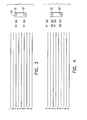
- Figs. 3-6 wherein nine raster scan lines on photoreceptor 36 are schematically illustrated and sequentially numbered. It is initially assumed that laser beams 32 and 32' are aligned to expose scan lines 1 and 4 (since laser beams 32 and 32' are separated by (n + 1) or 3 raster scan lines). During a first scan S1, laser beam 32 is modulated with image pixel data that is to be imprinted along scan line 1, whereas laser beam 32' is modulated by image pixel data that is to appear on scan line 4.
- each of the raster scan lines that is destined to be fed to laser diode 52 (so as to modulate laser beam 32) is listed in a raster line tag list A and each of the raster scan lines that is destined to be fed to laser diode 54 to modulate laser beam 32', is listed in raster line tag list B.
- a next pair of raster scan lines (one from raster line tag list A and one from raster line tag list B) are caused to modulate laser diodes 52, 54 and laser beams 32, 32'.
- a raster scan line of pixels (the one destined for scan line 6) is read out from raster buffer 18 under control of the next listed image raster line from raster line tag list B to modulate laser diode 54.
- the modulated laser beams 32 and 32' are scanned across photoreceptor 36 to achieve an exposure of each of scan lines 3 and 6.
- drum 38 is rotationally moved to reposition laser beams 32 and 32' into alignment with scan lines 5 and 8, respectively.
- the respective image pixel lines to modulate laser beams 32 and 32' are determined from raster line tag lists A and B
- the determined image pixel line data is then fed to respective laser diodes 52, 54 , causing scan lines 5 and 8 to be written on photoreceptor 36 as laser beams 32, 32' are concurrently scanned thereacross.
- the process continues, as shown in Fig. 6, until all of the image raster lines in raster buffer 22 have been written onto photoreceptor 36.
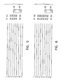
- Fig. 7 a three beam system is illustrated, showing the required spacings between each of the beams.
- the vertical beam spacing is (n + 1)p or 4p for the 3 beam array.
- the first to last beam spacing is 2(n + 1)p.
- a 4 beam system is illustrated.
- the angle ⁇ is the arctangent of 5/10 or 26.56505°.
- a 5 beam system is illustrated and shows the relative spacings between each of the respective laser beams.
Landscapes
- Engineering & Computer Science (AREA)
- Multimedia (AREA)
- Signal Processing (AREA)
- Physics & Mathematics (AREA)
- Optics & Photonics (AREA)
- General Engineering & Computer Science (AREA)
- General Physics & Mathematics (AREA)
- Theoretical Computer Science (AREA)
- Mechanical Optical Scanning Systems (AREA)
- Dot-Matrix Printers And Others (AREA)
- Facsimile Scanning Arrangements (AREA)
- Laser Beam Printer (AREA)
Abstract
Description
Leaving the p term out to get the relative spacing, 25 + 100 = 125 and the square root of 125 is 11.18034 times the desired dot pitch. The angle is the arctangent of 5/10 or 26.56505°.
For a given L, Lcos = a and Lsin = b. In order to have a fixed pitch, b = 2a and it follows that
Claims (10)
- A laser printer (10) for producing a raster image comprising plural raster scan lines of pixels, each raster scan line separated from an adjacent raster scan line by a pitch distance p, said printer comprising:a movable photoreceptor (36);n laser source means (52,54), where n ≥ 2, for producing n optical beams (32, 32') which, when incident on said photoreceptor (36), are separated by a distance of (n + 1)p in a direction of movement of said photoreceptor (36) and which, when incident on said photoreceptor (36), are offset with respect to each other in a direction perpendicular to the direction of movement of said photoreceptor (36);motive means (40) for moving said photoreceptor (36) with respect to said optical beams (32,32');scan means (34) for scanning said n optical beams (32,32') in parallel paths across said photoreceptor (36);image buffer memory means (18) for storing plural raster scan lines of pixel values comprising an image;control means (12,30) for modulating said n optical beams (32,32'), respectively, with pixel values from one set of n raster scan lines from said image buffer memory means (18) as said n optical beams (32,32') are scanned across said photoreceptor (36), each of said n raster scan lines of said one set separated by a distance of (n + 1)p on said photoreceptor (36), said control means (12,30) further causing said motive means (40) to move said photoreceptor (36) by a distance (n x p) prior to a start of each scan action of said scan means (34) and to again modulate said n optical beams (32, 32') with pixel values from another set of n raster scan lines that are, respectively, (nxp) distant from said n raster scan lines of said one set. ,
- The laser printer (10) as recited in claim 1, wherein said n laser source means (52,54) include n laser diodes, said n laser diodes positioned to emit laser beams (32,32') that are separated by a distance (n + 1)p measured along the direction of movement of said photoreceptor (36).
- The laser printer (10) as recited in claim 2, wherein said control means (12,30) includes means for selectively allocating raster scan line data to modulate said n laser diodes (52,54).
- The laser printer (10) as recited in claim 1, wherein n is an integer in a range of from two to five.
- The laser printer (19) as recited in one of claims 1 to 4, whereas the optical beams (32,32') when incident on said photoreceptor (36) are aligned in such way that the smallest distance between any two optical beams (32,32') when incident on said photoreceptor (36) is larger than the smallest distance between any two optical beams (32,32') when incident on said photoreceptor, measured in the direction of movement of said photoreceptor (36).
- The laser printer as recited in one of claims 1 to 5, whereas a main-extension, which is defined as the maximum distance between two optical beams (32,32') when incident on said photoreceptor (36), measured in the direction of movement of said photoreceptor, deviates from a sub-extenstion, which is defined as the maximum distance between two optical beams (32,32') when incident on said photoreceptor, measured in a direction perpendicular to the direction of movement of said photoreceptor (36), by no more than 50 percent.
- The laser printer as recited in one of claims 1 to 6, whereas n is equal to 3 and whereas the optical beams (32,32') when incident on said photoreceptor (36) are located at corners of an equilateral triangle, and whereas the equilateral triangle is rotated in such way that the optical beams (32,34') are spaced equidistantly in the direction of movement of said photoreceptor.
- The laser printer as recited in one of claims 1 to 6, whereas n is equal to 4, and whereas the optical beams (32,32') when incident on said photoreceptor (36) are located at corners of a square, and whereas the square is rotated in such way that the optical beams (32,34') when incident on said photoreceptor (36) are spaced equidistantly in the direction of movement of said photoreceptor.
- The laser printer as recited in one of claims 1 to 6, whereas n is equal to 5, and whereas the optical beams (32,32') when incident on said photoreceptor (36) are located at corners of a square and at the center thereof, and whereas the square is rotated in such way that the optical beams (32,34') when incident on said photoreceptor (36) are spaced equidistantly in the direction of movement of said photoreceptor.
- A method for controlling a laser printer (10) to produce a raster image comprising plural raster scan lines of pixels, each raster scan line separated from an adjacent raster scan line by a pitch distance p, said printer (10) including a movable photoreceptor (36), n laser source means (52,54), where n ≥ 2, for producing n optical beams (32,32') which, when incident on said photoreceptor (36), are separated by a distance of (n + 1)p in a direction of movement of said photoreceptor (36), and which, when incident on said photoreceptor (36), are offset in a direction perpendicular to the direction of movement of said photoreceptor (36), scan means (34) for scanning said optical beams (32,32') in parallel paths across said photoreceptor (36) and image buffer memory means (18) for storing plural raster scan lines of pixel values comprising an image, said method comprising the steps of:a. scanning said n optical beams (32,32') across said photoreceptor (36) while modulating said n optical beams (32'32'), respectively, with pixel values from one set of n raster scan lines from said image buffer means (18), each of said n raster scan lines of said one set separated by a distance of (n + 1)p when said image is transferred to a media sheet;b. moving said photoreceptor (36) by a distance (n x p) at an end of each scan of said n optical beams (32,32');c. modulating said n optical beams (32,32') with pixel value from another set of n raster scan lines that are, respectively, (n x p) distant from said n raster scan lines of said one set; andd. repeating steps a-c until said photoreceptor (36) has been exposed in accordance with all pixel values of said image.
Applications Claiming Priority (3)
| Application Number | Priority Date | Filing Date | Title |
|---|---|---|---|
| US08/583,393 US5691759A (en) | 1996-01-05 | 1996-01-05 | Method and apparatus for interleaving raster scan lines in a multi-beam laser imaging device |
| US583393 | 1996-01-05 | ||
| EP96114736A EP0783223A3 (en) | 1996-01-05 | 1996-09-13 | Method and apparatus for interleaving raster scan lines in a multi-beam laser imaging device |
Related Parent Applications (1)
| Application Number | Title | Priority Date | Filing Date |
|---|---|---|---|
| EP96114736A Division EP0783223A3 (en) | 1996-01-05 | 1996-09-13 | Method and apparatus for interleaving raster scan lines in a multi-beam laser imaging device |
Publications (2)
| Publication Number | Publication Date |
|---|---|
| EP1515536A2 true EP1515536A2 (en) | 2005-03-16 |
| EP1515536A3 EP1515536A3 (en) | 2005-03-23 |
Family
ID=24332932
Family Applications (2)
| Application Number | Title | Priority Date | Filing Date |
|---|---|---|---|
| EP96114736A Withdrawn EP0783223A3 (en) | 1996-01-05 | 1996-09-13 | Method and apparatus for interleaving raster scan lines in a multi-beam laser imaging device |
| EP04029850A Withdrawn EP1515536A3 (en) | 1996-01-05 | 1996-09-13 | Method and apparatus for interleaving raster scan lines in a multi-beam laser imaging device |
Family Applications Before (1)
| Application Number | Title | Priority Date | Filing Date |
|---|---|---|---|
| EP96114736A Withdrawn EP0783223A3 (en) | 1996-01-05 | 1996-09-13 | Method and apparatus for interleaving raster scan lines in a multi-beam laser imaging device |
Country Status (3)
| Country | Link |
|---|---|
| US (1) | US5691759A (en) |
| EP (2) | EP0783223A3 (en) |
| JP (1) | JPH09193468A (en) |
Families Citing this family (29)
| Publication number | Priority date | Publication date | Assignee | Title |
|---|---|---|---|---|
| JPH10145297A (en) * | 1996-11-08 | 1998-05-29 | Nec Corp | Feed forward distortion compensation system |
| JPH11115238A (en) * | 1997-10-09 | 1999-04-27 | Ricoh Co Ltd | Image forming device |
| US6290328B1 (en) * | 1998-02-05 | 2001-09-18 | Canon Kabushiki Kaisha | Multi-pass banded printing |
| US6037962A (en) * | 1998-04-03 | 2000-03-14 | Hewlett-Packard Company | Method and apparatus for interleaving raster scan lines in a multi-beam laser imaging device |
| KR100518517B1 (en) * | 1998-07-14 | 2005-11-25 | 삼성전자주식회사 | Laser scanning unit using multiple laser beam modules and laser beam printer having the laser scanning unit |
| US6037963A (en) * | 1998-07-28 | 2000-03-14 | Lexmark International, Inc. | Laser printer having variable beam spacing |
| US6359641B1 (en) * | 1998-09-24 | 2002-03-19 | Xerox Corporation | Multiple diode imaging system including a multiple channel beam modulation integrated circuit |
| US6222577B1 (en) * | 1999-01-26 | 2001-04-24 | Presstek, Inc. | Multiple-beam, diode-pumped imaging system |
| JP2001138572A (en) | 1999-11-16 | 2001-05-22 | Fujitsu Ltd | Image forming device |
| DE20023981U1 (en) | 2000-06-30 | 2008-06-19 | Heidelberger Druckmaschinen Ag | Compact multi-beam laser light source for the exposure of printing plates |
| DE10031915A1 (en) * | 2000-06-30 | 2002-01-10 | Heidelberger Druckmasch Ag | Compact multi-beam laser light source and interleaved scanning line method for exposure of printing plates |
| DE10108624A1 (en) | 2001-02-22 | 2002-09-05 | Heidelberger Druckmasch Ag | Banding-reducing imaging of a printing form |
| US6900826B2 (en) * | 2002-02-19 | 2005-05-31 | Presstek, Inc. | Multiple resolution helical imaging system and method |
| CA2418294A1 (en) * | 2002-03-08 | 2003-09-08 | Heidelberger Druckmaschinen Aktiengesellschaft | Imaging method for printing forms |
| US7116821B2 (en) * | 2002-03-25 | 2006-10-03 | Lexmark International, Inc. | Color trapping for an image forming apparatus |
| US6747684B2 (en) | 2002-04-10 | 2004-06-08 | Hewlett-Packard Development Company, L.P. | Laser triggered inkjet firing |
| US7104623B2 (en) * | 2002-06-07 | 2006-09-12 | Hewlett-Packard Development Company, L.P. | Fluid ejection system with photosensor activation of ejection element |
| US6799819B2 (en) | 2002-06-07 | 2004-10-05 | Hewlett-Packard Development Company, L.P. | Photosensor activation of an ejection element of a fluid ejection device |
| US6705701B2 (en) * | 2002-06-07 | 2004-03-16 | Hewlett-Packard Development Company, L.P. | Fluid ejection and scanning system with photosensor activation of ejection elements |
| US7083250B2 (en) * | 2002-06-07 | 2006-08-01 | Hewlett-Packard Development Company, L.P. | Fluid ejection and scanning assembly with photosensor activation of ejection elements |
| US6867794B2 (en) * | 2003-01-30 | 2005-03-15 | Hewlett-Packard Development Company, L.P. | Adjusting a scan line in a laser imaging device |
| US7042484B2 (en) * | 2003-03-20 | 2006-05-09 | Hewlett-Packard Development Company, L.P. | Scan line length adjustment |
| US7012246B1 (en) * | 2004-08-23 | 2006-03-14 | Lexmark International, Inc. | Multiple light beam imaging apparatus |
| JP4912006B2 (en) | 2006-03-24 | 2012-04-04 | 大日本スクリーン製造株式会社 | Image recording device |
| WO2008004047A2 (en) * | 2006-06-30 | 2008-01-10 | Kodak Graphic Communications Canada | Methods and apparatus for selecting and applying non-contiguous features in a pattern |
| GB2452205B (en) * | 2006-06-30 | 2011-04-13 | Kodak Graphic Comm Canada Co | Forming an image with a plurality of imaging heads |
| WO2011135848A1 (en) * | 2010-04-28 | 2011-11-03 | パナソニック株式会社 | Scan-type image display device |
| JP2020016529A (en) * | 2018-07-25 | 2020-01-30 | 株式会社リコー | Object detector and object detection method |
| CN118963069B (en) * | 2024-07-31 | 2025-09-26 | 深圳市先地图像科技有限公司 | Laser scanning imaging control method, system and related equipment |
Family Cites Families (7)
| Publication number | Priority date | Publication date | Assignee | Title |
|---|---|---|---|---|
| US4905025A (en) * | 1988-06-20 | 1990-02-27 | Dainippon Screen Mfg. Co., Ltd. | Method of and apparatus for recording image on photosensitive material with a plurality of photobeams |
| US4989019A (en) * | 1990-01-25 | 1991-01-29 | Xerox Corporation | Multi-beam scanning system compensated for banding |
| US5471236A (en) * | 1991-02-28 | 1995-11-28 | Fuji Xerox Co., Ltd. | Multi-beam scan optical system |
| JPH0773134B2 (en) * | 1991-02-28 | 1995-08-02 | 富士ゼロックス株式会社 | Multi-beam semiconductor laser array and multi-beam laser printer |
| US5430472A (en) * | 1991-07-29 | 1995-07-04 | Xerox Corporation | Method and apparatus for eliminating distortion via overscanned illumination for optical printers and the like having high gamma photosensitive recording media and high addressability |
| US5305022A (en) * | 1992-03-24 | 1994-04-19 | Fuji Xerox Co., Ltd. | Interlaced multi-beam scanning type recording apparatus |
| US5233367A (en) * | 1992-09-18 | 1993-08-03 | Xerox Corporation | Multiple beam interlaced scanning system |
-
1996
- 1996-01-05 US US08/583,393 patent/US5691759A/en not_active Expired - Lifetime
- 1996-09-13 EP EP96114736A patent/EP0783223A3/en not_active Withdrawn
- 1996-09-13 EP EP04029850A patent/EP1515536A3/en not_active Withdrawn
- 1996-12-24 JP JP8342894A patent/JPH09193468A/en active Pending
Also Published As
| Publication number | Publication date |
|---|---|
| EP0783223A2 (en) | 1997-07-09 |
| EP0783223A3 (en) | 1999-02-10 |
| JPH09193468A (en) | 1997-07-29 |
| EP1515536A3 (en) | 2005-03-23 |
| US5691759A (en) | 1997-11-25 |
Similar Documents
| Publication | Publication Date | Title |
|---|---|---|
| US5691759A (en) | Method and apparatus for interleaving raster scan lines in a multi-beam laser imaging device | |
| EP0263143B1 (en) | High resolution optical scanner | |
| JPH0451829B2 (en) | ||
| EP0713323B1 (en) | Multispot polygon ros with maximized line separation depth of focus | |
| US8928720B2 (en) | Apparatus and method of scanning light using an array of light sources | |
| US5274394A (en) | Electronic adjustment of slow scan image registration in an image recording apparatus | |
| EP0947950B1 (en) | Method and apparatus for interleaving raster scan lines in a multi-beam laser imaging device | |
| US4884857A (en) | Scanner for use in multiple spot laser electrophotographic printer | |
| JP2008213243A (en) | Optical scanning apparatus, optical scanning method, program, recording medium, and image forming apparatus | |
| US5461413A (en) | Laser array printing | |
| US6825457B2 (en) | Two-dimensional beam writing position detecting device and image forming apparatus using the detecting device | |
| EP0843192B1 (en) | Scanning optical device | |
| JPH09281420A (en) | Laser beam scanning optical device | |
| US7667727B2 (en) | Multiple-beam raster output scanner with a compensating filter | |
| EP0549204A1 (en) | Spot position control in a raster output scanning device | |
| US20050007443A1 (en) | Beam scanning apparatus and image forming apparatus using the same | |
| JP3832087B2 (en) | Optical beam scanning optical device | |
| CN100476501C (en) | Light beam scanning device and image forming apparatus | |
| EP0782928B1 (en) | Color xerographic printer with multiple linear arrays of surface emitting lasers with the same wavelengths | |
| JPH06217086A (en) | Optical scanning device | |
| US20070046772A1 (en) | Image forming apparatus and image forming method | |
| US5764273A (en) | Spot position control using a linear array of light valves | |
| JPH08234126A (en) | Raster scanning optical system | |
| JP3686508B2 (en) | Image forming apparatus | |
| JP2022110975A (en) | image forming device |
Legal Events
| Date | Code | Title | Description |
|---|---|---|---|
| PUAI | Public reference made under article 153(3) epc to a published international application that has entered the european phase |
Free format text: ORIGINAL CODE: 0009012 |
|
| PUAL | Search report despatched |
Free format text: ORIGINAL CODE: 0009013 |
|
| 17P | Request for examination filed |
Effective date: 20041216 |
|
| AC | Divisional application: reference to earlier application |
Ref document number: 0783223 Country of ref document: EP Kind code of ref document: P |
|
| AK | Designated contracting states |
Kind code of ref document: A2 Designated state(s): DE FR GB |
|
| AK | Designated contracting states |
Kind code of ref document: A3 Designated state(s): DE FR GB |
|
| AKX | Designation fees paid |
Designated state(s): DE FR GB |
|
| STAA | Information on the status of an ep patent application or granted ep patent |
Free format text: STATUS: THE APPLICATION HAS BEEN WITHDRAWN |
|
| 18W | Application withdrawn |
Effective date: 20060215 |