EP1515526A1 - Multicolour illumination system for displaying the status of an electronic device - Google Patents
Multicolour illumination system for displaying the status of an electronic device Download PDFInfo
- Publication number
- EP1515526A1 EP1515526A1 EP04021742A EP04021742A EP1515526A1 EP 1515526 A1 EP1515526 A1 EP 1515526A1 EP 04021742 A EP04021742 A EP 04021742A EP 04021742 A EP04021742 A EP 04021742A EP 1515526 A1 EP1515526 A1 EP 1515526A1
- Authority
- EP
- European Patent Office
- Prior art keywords
- plate
- screen
- light
- light source
- source elements
- Prior art date
- Legal status (The legal status is an assumption and is not a legal conclusion. Google has not performed a legal analysis and makes no representation as to the accuracy of the status listed.)
- Granted
Links
Images


Classifications
-
- H—ELECTRICITY
- H04—ELECTRIC COMMUNICATION TECHNIQUE
- H04M—TELEPHONIC COMMUNICATION
- H04M1/00—Substation equipment, e.g. for use by subscribers
- H04M1/02—Constructional features of telephone sets
- H04M1/22—Illumination; Arrangements for improving the visibility of characters on dials
-
- H—ELECTRICITY
- H04—ELECTRIC COMMUNICATION TECHNIQUE
- H04M—TELEPHONIC COMMUNICATION
- H04M1/00—Substation equipment, e.g. for use by subscribers
- H04M1/02—Constructional features of telephone sets
- H04M1/0202—Portable telephone sets, e.g. cordless phones, mobile phones or bar type handsets
- H04M1/0206—Portable telephones comprising a plurality of mechanically joined movable body parts, e.g. hinged housings
- H04M1/0208—Portable telephones comprising a plurality of mechanically joined movable body parts, e.g. hinged housings characterized by the relative motions of the body parts
- H04M1/0214—Foldable telephones, i.e. with body parts pivoting to an open position around an axis parallel to the plane they define in closed position
-
- H—ELECTRICITY
- H04—ELECTRIC COMMUNICATION TECHNIQUE
- H04M—TELEPHONIC COMMUNICATION
- H04M19/00—Current supply arrangements for telephone systems
- H04M19/02—Current supply arrangements for telephone systems providing ringing current or supervisory tones, e.g. dialling tone or busy tone
- H04M19/04—Current supply arrangements for telephone systems providing ringing current or supervisory tones, e.g. dialling tone or busy tone the ringing-current being generated at the substations
- H04M19/048—Arrangements providing optical indication of the incoming call, e.g. flasher circuits
Abstract
Description
- This invention relates to an illumination system for illuminating surface of various kinds of device with colored lights. The lights are cast from the inside of the device to the surface to project an image such as an emblem, symbol, trademark and geometrical pattern on the surface. Particularly, the illumination system is suitably incorporated with a portable electronic device.
- Recently, some of portable electronic devices such as a portable telephone terminal, PDA (personal data assistant) and wrist watch have a illumination system for emitting various color lights in response to a predetermined action of the devices.
- For example, a illumination system of a portable telephone terminal project an emblem on the surface of the portable telephone terminal when the terminal receives a call, or during the terminal is establishing a connection with another telephone terminal.
- A
portable telephone terminal 101 shown in Fig. 1 has afoldable housing 102 and is now folded in Fig. 1. On anupper housing 103, anconventional illuminator 104, anauxiliary display device 105 and anantenna 106 is installed. Theilluminator 104 emits light to indicate an arrival of a call or establishment of a connection with another telephone terminal. Thesub display device 105 displays information when thefoldable housing 102 is folded. Theantenna 106 directs incoming and outgoing radio waves. - As shown in Fig. 2, the
illuminator 104 includes alight source unit 107 and ascreen 108. As shown in Fig. 3, thelight source unit 107 includes ared LED 107r, agreen LED 107g and ablue LED 107b on a print-circuit plate. Lights emitted from the LEDs are cast on thescreen 108. - The LEDs blink according to a predetermined blinking pattern in order to cast a single one or a mixture of two or three colors on the screen 109. For example, if the blinking pattern consists of combinations of ON/OFF of the LEDs, then the
screen 108 is colored in one of red, green, blue, yellow, cyan, magenta, white and black. - Whichever a single LED or plural LEDs emit, a single color is cast on the
screen 108 at one time as shown in Fig. 4. Therefore, thescreen 108 cannot be divided into plural areas each of which has a different color from each other. Consequently, it is unable to express on thescreen 108 that an object with a color moves on a background with another color. - Related arts are disclosed on Japanese Patent Publication No. 2001-166738, in which a group of LEDs including a red, green and blue LEDs
- This invention provides the following an illumination system and an electronic device with the illumination system.
- According to one aspect of the present invention, an illumination system including: light source elements including at least a first element for emitting a first color light and a second element for emitting a second color light whose color is different from the first color light; a screen cast the first and second color lights from the light source elements; and a plate which is placed between the light source elements and the screen, and comprises first areas and second areas, the first and second areas having different properties of conducting light from each other, wherein: the first color light is cast through the plate on a first spot of the screen; the second color light is cast through the plate on a second spot of the screen; and the first and second spots overlap with each other is provided.
- The light source elements are for example arranged in line with each other. Alternatively, the light source elements may be arranged in vertexes of a polygon. The light axes of the light source elements are preferably parallel but offset with each other.
- The first areas of the plate may be openings opened through the plate. It is preferable that the arrangement of the first and second areas on the plate expresses a design to be cast on the screen.
- The plate may be a transparent or translucent plate. In this case, the plate is partially painted with lightproof paint as the second areas. Alternatively, the plate may be an opaque plate with penetrable areas for conducting light. In this case, the penetrable areas may be openings opened through the plate, or transparent members fit into the plate.
- The light source elements may be dots emitting light. The light source elements may include a red, green and blue light source elements for emitting red, green and blue light, respectively. Instead, the light source elements may include a cyan, magenta and yellow light source elements for emitting cyan, magenta and yellow light, respectively. Further, light emitted from one of the red, green and blue light source elements may be partially mixed with a part of light emitted from the other. Similarly, light emitted from one of the cyan, magenta and yellow light source elements may be partially mixed with a part of light emitted from the other.
- Each of the light source elements may blink according to a predetermined blinking pattern. In this case, for example, the blinking pattern is predetermined according to the shape of the first and/or second area and to the arrangement of the first and second areas on the plate. The blinking pattern may be predetermined according to the arrangement of the plate, the light source elements and the screen. The blinking pattern may be predetermined according to the arrangement of the light source elements.
- At least one filter member may be placed between the plate and the light source elements or between the plate and the screen.
- At least one of the plate and the screen may be detachable from the illumination system. The plate and the screen may be integrated with each other.
- The screen is for example a transparent or translucent plate with a diffusion layer on at least one surface of the plate. In this case, the diffusion layer diffuses light from the light source elements. The diffusion layer is preferably a white layer. The diffusion layer may be formed on a part of a surface of the plate. In this case, the diffusion layer and the rest of the surface express a design to be illuminated with the light from the light source elements.
- Additionally, according to another aspect of the present invention, an electronic device including the above-mentioned illumination system is provided. One example of the electronic device is a portable communication device. In this case, it is preferable that the illumination system is activated in response to a predetermined operation of the portable communication device.
- According to one aspect of this invention, light sources emit colors each of which is different from each other. Part of one of the colors is directly cast on a screen as it has been emitted. Other part of the color is mixed with a singular or plural other colors and then cast on the screen. As a result, gradual color change occurs on the screen and therefore, according to the present invention, decorativeness of a portable electronic device can be improved.
- According to another aspect of the present invention, pattern cast on the screen is changed in accordance with emissions from the light sources. The emissions are controlled by inputs to the light sources. Therefore, according to the present invention, temporal response of the cast pattern can be easily made.
- According to another aspect of the present invention, spots of a color mixture are cast on the screen. For example, it is assumed that the light sources are red, green and blue light emitting elements each of which is controlled by on/off switching. In this case, when the emitting elements are switched in response to a suitable switching pattern, the spot seems to move around on the screen. This aspect provides visual amusement on the screen.
- According to another aspect of the present invention, various sizes of light spots are cast on the screen at the same time to supply perspective on the screen.
- These aspects are achieved by a simple structure including a conduit plate between the screen and the light sources. No moving parts are required. Therefore, the present invention can be easily implemented in portable electronic devices, e.g. cellular phone terminals, without disturbing miniaturization, weight saving, low-profiling and lowering the cost of production of the devices.
-
- Fig. 1 shows a top view of a folding communication device with an illumination system with being folded;
- Fig. 2 shows a schematic diagram of a conventional illumination system;
- Fig. 3 shows a cross section diagram of the conventional illumination system shown in Fig. 2;
- Fig. 4 shows a screen view cast by the conventional illumination system shown in Figs. 2 and 3;
- Fig. 5 shows a top view of a folding communication device with an illumination system of a first embodiment of the present invention when it is folded;
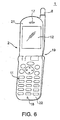
- Fig. 6 shows a top view of the folding communication device shown in Fig. 5 with being unfolded;
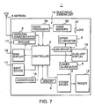
- Fig. 7 shows a block diagram of the folding communication device shown in Figs. 5 and 6;
- Fig. 8 shows a cross section diagram of a sub screen including the illumination systems of the first embodiment;
- Fig. 9 shows a schematic diagram of the illumination system of the first embodiment;
- Fig. 10 shows an arrangement of three light emitting elements;
- Fig. 11 shows an example of cover for covering a sub screen of the folding communication device;
- Fig. 12 shows a cross section diagram of the illumination system of the first embodiment;
- Fig. 13 shows a schematic diagram for use in describing the screen cast colored lights from the light emitting elements;
- Fig. 14 shows a block diagram for use in describing an
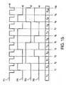
LED driver 7; - Fig. 15 shows a timing chart for use in describing switching of the light emitting elements;
- Fig. 16A shows a schematic diagram for use in describing movement of light spots on the screen;
- Fig. 16B shows a schematic diagram for use in describing movement of light spots on the screen;
- Fig. 16C shows a schematic diagram for use in describing movement of light spots on the screen;
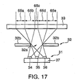
- Fig. 17 shows a schematic cross section diagram of the illumination system of the first embodiment;
- Fig. 18A shows a schematic cross section diagram for use in describing movement of light spots on the screen;
- Fig. 18B shows a schematic cross section diagram for use in describing movement of light spots on the screen;
- Fig. 19 shows a cross section diagram of a screen of a second embodiment of the present invention;
- Fig. 20 shows a cross section diagram of a screen of a third embodiment of the present invention; and
- Fig. 21 shows a top view of the screen of the third embodiment.
-
- Description will be made about a first embodiment of the present invention. The first embodiment is a
portable communication device 1, e.g. a cellular telephone terminal. With reference to Figs. 5 and 6, theportable communication device 1 has afoldable housing 2 which includes anupper housing 21 and alower housing 22. Theupper housing 21 andlower housing 22 are connected with each other via ahinge 19 and rotate on thehinge 19 to fold/unfold thefoldable housing 2. - As shown in Fig. 7, in the
foldable housing 2, theportable communication device 1 includes acontroller 3, amemory 4, anupper illuminator 5, alower illuminator 6, aLED driver 7, anantenna 8, awireless communicator 9, aninput device 11, amain display 12, anauxiliary display 13, anelectronic camera unit 14, aringer 15, aringer driver 16, aspeaker 17, and amicrophone 18. - The
controller 3 includes a CPU (Central Processing Unit) which reads/writes thememory 4 and executes programs stored in thememory 4 to control other units of theportable communication device 1. For example, the following programs are executed on the controller 3: a communication control program for controlling communication procedures such as sending a call to a telephone number; a input control program for processing data input via key switches of theinput device 11; an illumination control program for controlling theLED driver 17 to switch LEDs of theupper illuminator 5 and/or thelower illuminator 6 in response to receiving a call and while establishing a connection between other communication device; a display control program for controlling themain display 12 andauxiliary display 13 to display image data (e.g. image data generated by the electronic camera unit 14); a web browser program for communicating with a web server and interpreting web page data; a mailer program for communicating with a mail server and managing mail data and so on. - The
memory 4 stores program executed by thecontroller 3 and data read/written by thecontroller 3. Thememory 4 consists of semiconductor memory and has a program storage area and a data storage area. The program storage area stores the above-mentioned programs. The data storage area stores data of configuration, communication log, address book, blinking pattern and so on. According to the blinking pattern information data, the upper andlower illuminators electronic camera unit 14, register data and flag data for executing a program on thecontroller 3. - According to the illumination control program, in response to receiving a call or while establishing a connection, the
controller 3 makes LEDs of the upper andlower illuminators - The illumination control program states the procedure that, in response to receiving a call or while establishing a connection, the
controller 3 makes the LEDs of the upper andlower illuminators lower illuminators - The blinking pattern data are time series data. Each of the upper and
lower illuminators - In this embodiment, the upper and
lower illuminators portable communication device 1. - As shown in Figs. 5 and 8, two illumination systems, or the upper and
lower illuminators auxiliary display 13, respectively. Theupper illuminator 5 includes alight source unit 31, aconduit plate 32 and ascreen 33, as shown in Fig. 9. Similarly, thelower illuminator 6 includes alight source unit 43, aconduit plate 44 and ascreen 45. Hereinafter the description about theupper illuminator 5 is basically adaptive to that about thelower illuminator 6. - As shown in Fig. 9, the
conduit plate 32 is inserted between thelight source unit 31 and thescreen 33. Theconduit plate 32 has penetrable areas 32a1, 32a2, 32a3, ... andopaque area 32b. The penetrable areas 32a1, 32a2, 32a3, ... can transmit light and may be made of translucent or transparent material, or openings through theconduit plate 32. Theopaque area 32b blocks the passage of light from thelight source unit 31. Therefore, lights emitted from thelight source unit 31 are cast on thescreen 33 via the penetrable areas 32a1, 32a2, 32a3, .:. on theconduit plate 32. - In this embodiment, the penetrable areas are openings on the
conduit plate 32. Theconduit plate 32 is an opaque substrate, at least one of surfaces of which is covered with a opaque layer. The openings 32a1, 32a2, 32a3, ... are formed predetermined positions on the opaque substrate. - The openings have an approximate circle form and are regularly formed on the substrate. In this embodiment, the diameter of the openings is about 0.5 mm, the pitch of the openings is about 1.0 mm.
- As shown in Fig. 12, the
light source unit 31 includes ared LED 34, a green LED 35 ablue LED 36 and a PCB (printed-circuit plate) 37. TheLEDs PCB 37 in order that the centers of theLEDs PCB 37. Each light rays from theLEDs - With reference to Figs. 8 and 11, the
upper illuminator 5, thelower illuminator 6 and theauxiliary display 13 are covered with acover 38, which is made of translucent material, except for atransparent window 39. Image displayed on theauxiliary display 13 is transmitted through thetransparent window 39 toward its user's eyes. Thescreens cover 39 to oppose thelight source units screen 33 has awhite layer 41 for diffusing light from thelight source unit 31. Similarly, thescreen 46 has awhite layer 45 for diffusing light from thelight source unit 43. - The distance between the
light source unit 31 and theconduit plate 32, the distance between theconduit plate 32 and thescreen 33, the sizes, forms and arrangement of the penetrable areas 32a1, 32a2, ..., and the arrangement of thered LED 34, thegreen LED 35 and theblue LED 36 on thePCB 37 are predetermined based on an illumination pattern to be displayed on thescreen 33. For example, they are experimentally predetermined. The illumination pattern expresses arrangement of colors and temporal response of the arrangement on thescreen 33. Namely, the illumination pattern may be change of patterns displayed on thescreen 33, change of color arrangement in a pattern, and combination of these changes. The illumination pattern actuary displayed on thescreen 33 is eventually determined based on the blinking pattern of the LEDs. In this embodiment, the distance between thelight source unit 31 and theconduit plate 32 is about 0.3 mm, and the distance between theconduit plate 32 and thescreen 33 is about 1.0 mm. - The light emitted from the LEDs passes thorough routes described as following and as shown in Fig. 12.
- The light rays emitted from the
LEDs conduit plate 32, passes thorough the openings 32a1, 32a2, 32a3, 32a4 and 32a5 on theconduit plate 32, and then arrive on thescreen 33. - The opening 32a1 is opened at a position on the
conduit plate 32 where the light from thegreen LED 35 and theblue LED 36 seldom or never arrive. Therefore, the light passing through the opening 32a1 is almost red light. Similarly, the light passing through the opening 32a5 is almost blue light. Namely, the opening 32a1 mainly conducts red light and the opening 32a5 mainly conducts blue light. Each of the rest openings 32a2, 32a3 and 32a4 conducts red, green and blue light. Therefore, the colors of the light rays through the openings 32a2, 32a3 and 32a4 are mixtures of red, green and blue, although the mixtures have a different mixing ratio of red, green and blue from each other. - The light rays through the openings 32a1, 32a2, 32a3, 32a4 and 32a5 are mixed between the
conduit plate 32 and thescreen 33 and then cast on thescreen 33. In Fig. 12, red light is cast on the left end of thescreen 33, blue light is cast on the right end of thescreen 33, and between the left and right ends of thescreen 33, mixed color light whose mixing ratio is dependent on a position on thescreen 33 is cast on thescreen 33. - As a result, red, green, blue spots of light are cast on the
screen 33, spots having a mixed color of two or three of red, green and blue are cast on thescreen 33, and in addition, these spots cast from openings on theconduit plate 32 are partly cast on a same area of thescreen 33 with each other to make another color on the area. - For example, as shown in Fig. 13, each of a primary color (red, green or blue)
spot 41a, anyellow spot 41b, amagenta spot 41c, acyan spot 41d and awhite spot 41e is cast through an opening on theconduit plate 33. Theyellow spot 41b is partly cast on the same area with thewhite spot 41e. As a result, the union of thespots screen 33 has a different color from both yellow and white from the opening on theconduit plate 32. Similarly, mixture colors of the primary color and white, magenta and white and cyan and white appear on thescreen 33. - The
LED driver 14 includes a FIFO (First In First Out memory) 51, anoutput port register 52, a read-outsignal generating circuit 53, and a drivesignal output circuit 54. TheFIFO 51 read blinking pattern data of the LEDs from thememory 4 and outputs in queue order. The output port register 52 stores output from theFIFO 51 and outputs to the drivesignal output circuit 54. The read-outsignal generating circuit 53 outputs a read-out signal to theFIFO 51 in accordance with a clock signal. The drivesignal output circuit 54 outputs drive signal for driving the LEDs of the upper andlower illuminators - The
wireless communicator 9 includes a RF (radio frequency) circuit, a modulator/demodulator circuit, a base band circuit and so on. Thewireless communicator 9 modulates sound or other data to radio waves, outputs the radio waves via theantenna 8, receives radio waves via theantenna 8, demodulates the radio waves to sound or data, establishes voice or data communication in accordance with predetermined protocols. - The
input device 11 is a keypad for example including cursor keys for inputting a direction to move a cursor on themain display 12, numeric keys for inputting numbers, and function keys related to predetermined functions of theportable communication device 1. For example, function keys are browser key for executing a browser program on theportable communication device 1 to display web pages on themain display 12, an enter key for confirming user input, menu keys for displaying function menu of theportable communication device 1 on themain display 12, an input method switching key for switching input method, an address book key for displaying an address book on themain display 12, a clear key for erasing input or return state of themain display 12, a power key for turning on/off theportable communication device 1, and a camera key for activating theelectronic camera unit 14 and for pressing the shutter of thecamera unit 14. - The
main display 12 is for example a transmissive LCD and is arranged on a front face of theupper housing 21 which is aligned with a front face of thelower housing 22 when theportable communication device 1 is folded. Themain display 12 includes an LCD panel, a backlight, and a driver circuit. - The LCD panel is for example a transmissive liquid crystal display panel with TFT (Thin Film Transistor) structure, which includes a TFT substrate embedded TFTs and transparent pixel electrodes, an opposite substrate which includes a color filer and opposes to the TFT substrate with several-micrometer-gap, and a pair of polarizes arranged outside of the substrates.
- The
auxiliary display 13 is for example a transmissive LCD panel and is arranged on a back face of theupper housing 21, which displays time, arrival of calling, receiving a mail etc. when theportable communication device 1 is folded. - As shown in Figs. 5 and 7, the
electronic camera unit 14 includes ahole 56, alens 57,image sensors 58 and animage processor 59. Thehole 56 is arranged on the back face of theupper housing 21 to guide the light coming from objects to thelens 57. Thelens 57 is arranged in thehole 56, is for example a standard lens and focuses on theimage sensors 58. Theimage sensors 58 are for example CCD (Charge Coupled Devices) and transform photon flux thorough thelens 57 into a charge. Theimage processor 59 performs analog to digital translation to translate from analog image signals output by theimage sensors 58 to digital image signals and applies gamma correction, color space conversion and/or other image processing to the digital image signals. - Next, description will be made about the operation of the
portable communication device 1. - After turning the
portable communication device 1 on, thecontroller 3 enters a waiting mode for standing by for inputting via theinput device 11 or receiving a call from another communication device, and displays on themain display 12 that theportable communication device 1 is in the waiting mode. - When the
device 1 is in the waiting mode, in response to inputting via thedevice 1 or receiving a call, thecontroller 3 controls theLED driver 7 to blink the red, green andblue LEDs light source unit 107 according to a predetermined blinking pattern data. As a result, a desired illumination pattern corresponding to the blinking pattern data is performed on thescreens - Namely, the
controller 3 reads the blinking pattern data from thememory 4 and writes it to theFIFO 51. Then, as shown in Fig. 15, the read-outsignal generating circuit 53 generates a read-out signal P1 according to a clock signal. Thecircuit 53 starts this signal generation in response to a start signal that is output from thecontroller 3. - In response to the read-out signal P1, the
FIFO 51 writes the blinking pattern data to theoutput port register 52. Theoutput port register 52 outputs port output signals PR, PG and PB for driving the red, green and blue LEDs respectively. The drivesignal output circuit 54 drives the LEDs according to the port output signals PR, PG and PB. - As described above, the
FIFO 51 sequentially outputs the blinking pattern data to theoutput port register 52 and then the amount of the data that remains in theFIFO 51 reduces. When the remaining data becomes a predetermined amount, theFIFO 51 requests thecontroller 3 to provide additional data. In response to the request, according to the amount of the free space in theFIFO 51, thecontroller 3 reads the following blinking pattern data from thememory 4 and then sets the data to theFIFO 51. - As shown in Fig. 15, before the time instant t1 at which the
controller 3 detects receiving a call, namely in a unit time period T1 (t | t1), all of the port output signals PR, PG and PB are low or L. In this time period, the red, green andblue LEDs - Next, in a time period T2 (t1| t | t2), the port output signals PR, PG and PB are H, L and L, respectively and only the
red LED 34 emits to cast red light on the screen. - Similarly: in a unit time period T3 (t2 | t | t3), only the port output signal PG is H; in a unit time period T4 (t3 | t | t4), only the signal PR is L; in a period T5 (t4 | t | t5), only the signal PB is L; in a period T6 (t5 | t | t6), only the signal PG is L; in a period T7 (t6 | t | t7), only the signal PR is H; in a period T8 (t7 | t | t8), all of the signals PR, PG and PB are L; in a period T9 (t8 | t |9), all of the signals PR, PG and PB are H; and; in a unit time period T10 (t9 | t | t10), only the port output signal PR is L.
- In the periods T4, T5, T6, T9 and T10, two or three LEDs emit at once and two or three color light rays are cast on the
conduit plate 32. Some colors are mixed through theconduit plate 32 and then original colors emitted by the LEDs and the mixture colors are cast on thescreen 33. For example, in the period T9, red, green and blue are mixed through theconduit plates 32 to produce white. Two of red, green and blue are mixed through theconduit plates 32 to produce yellow, magenta or cyan. On thescreen 33, two of red, green, blue, white, yellow, magenta and cyan are mixed to produce another color. - For example, illumination pattern appears on the
screens screen 33 in a series of three time periods. - In Fig. 16A, three
spotlights screen 33 for a first unit time period. The sizes and colors of thespotlights - In a second period, as shown in Fig. 16B, three
spotlights spotlights spotlights spotlights spotlights spotlights spotlights spotlights - In a third period, as shown in Fig. 16c, three
spotlights spotlights spotlights spotlights spotlights spotlights spotlights spotlights - The size of a spot on the screen caused by a light ray from a LED depends on the distance between the LED and the hole through which the light ray is cast on the screen. If the source LED is closer to the hole, then the spot is larger. Therefore, the sizes and positions of spots on the screen change in response to blinking of the red, green and
blue LEDs - With reference to Fig. 16A, 16B and Fig. 16C, the
spot 61a seems to move to thespot 62b and then to move to thespot 63c. Thespot 61b seems to move to thespot 62c and then to move thespot 63a. Thespot 61c seems to move to thespot 62a and then to move to thespot 63b. Namely, the spots seem to revolve in the screen. Further, color of an area of the screen seems to change. - Herein, the structure of the
upper illuminator 5 will be described in detail. As shown in Fig. 17, it is assumed that relatively largepenetrable area 32a is installed at the center of theconduit plate 32 and the distance between thered LED 34 and theblue LED 36 is longer than that between the other combinations of the LEDs. - In the time period T9 of Fig. 15, namely when all of the LEDs are on, each of red, green and blue rays is cast through the
penetrable area 32a on thescreen 33. - On the screen 33: an
area 65a mainly receives blue light; anarea 65b mainly receives blue and green light to produce cyan; anarea 65c receives red, green and blue light to produce white; anarea 65d mainly receives red and green light to produce yellow; and anarea 65e mainly receives red light. Blue, cyan, white, yellow and red are displayed on thearea screen 33 displays plural colors at once. It is noted that, in conventional techniques, there is noconduit plate 32 between thelight source 37 and thescreen 33 so that all areas on the screen only displays white. - From the period T4 to T5, the
screen 33 displays as shown in Fig. 18A and 18B. In the period T4, the green andblue LEDs blue area 66a, acyan area 66b and agreen area 66c on thescreen 33. Then, in the period T5, the red andgreen LEDs green area 67a, ayellow area 67b and ared area 67c on thescreen 33. As a result, spots on thescreen 33 seem to move from theareas - As described above, spots on the
screen 33 are displayed as if they move around on thescreen 33 with changing their colors. Similarly to theupper illuminator 5, thelower illuminator 6 operates to display spots on thescreen 46. In this embodiment, thecontroller 3 makes theLED driver 7 blink the red, green andblue LEDs screens portable communication device 1 receives a call, but also while theportable communication device 1 is establishing a connection to another communication device. - According to this embodiment, the LEDs emit colors that are different from each other and cast all of the colors on the screen at once. Compared with this embodiment, according to a conventional system, even if the system includes plural LEDs that emit different colors from each other, only a single color is cast on the screen at once.
- According to this embodiment, colors are cast through a penetrable area on the conduit plate, and then the colors partially overlap with each other on the screen to produce other colors. Therefore, the number of colors displayed on the screen at once further increases.
- According to the embodiment, each of the LEDs blinks in accordance with a different blinking pattern. A blinking pattern of a LED is independent on that of another LED. In this embodiment, three LEDs are installed and consequently, one of 2Λ3 = 8 patterns is available for being displayed at one time period on the screen. Moreover, in case of defining a series of ten patterns as an illumination pattern, the number of illumination patterns is 8^10 = 1073741824. A lot of illumination patters each of which may include combinations of plural colors are available for displaying on the screen.
- According to this embodiment, although both the LEDs and the conduit plate are fixed, color spots on the screen are displayed as if the spots revolve around with changing their colors. Therefore, the illumination system improves visual amusement of the
portable communication device 1. - The sizes of spots displayed on the screen are different from each other. This difference supplies perspective to the screen. Therefore, in spite of its simple structure, the illumination system of this embodiment provides perspective decoration on the screen.
- As mentioned above, according to this embodiment, the appearance and amusement of the
portable communication device 1 are improved. This improvement depends on the conduit plate between the LEDs and the screen. All of these are fixed elements. Therefore, the illumination system can be installed into a device without preventing miniaturization, weight saving, reducing the thickness and cost of the device. - Description will be made about a second embodiment of the present invention with reference to Fig. 19. Compared to the illumination system of the first embodiment, a
screen 33A of the second embodiment corresponding to thescreen 33 has another structure. Thescreen 33A includes atransparent plate 39 and awhite layer 41a that covers the exit surface of thetransparent plate 39. The incoming surface of thetransparent plate 39 faces thelight source unit 31 and the exit surface of thetransparent plate 39 faces outside of theportable communication device 1. - In an illumination system including a screen with a white layer on its incoming surface of a transparent plate, light rays focus images on the white layer and do not travel thorough the transparent plate. On the other hand, in the illumination system including the
screen 33A, light rays travel through thetransparent plate 39 and then focus on thewhite layer 33A. Therefore, thescreen 33A displays larger images and their movement on thewhite layer 41a than the screen including the white layer on the incoming surface does. As a result, more dynamic movement of spots is displayed on thescreen 33A than on thescreen 33. - Description will be made about a third embodiment of the present invention. According to the third embodiment, the illumination system includes a
screen 33B as shown in Figs. 20 and 21. Thescreen 33B includes, as shown in Fig. 20, atransparent plate 39, awhite layer 41b on the exit surface of theplate 39 and anotherwhite layer 41c on the incoming surface of theplate 39. Thewhite layers white layer white layer 41b is star-shaped and thewhite layer 41c has a star-shaped hole, which corresponds to the shape of thewhite layer 41b, at its center. - According to this embodiment, since there is a light path difference between the
white layers white layer 41b. - While this invention has thus far been described in conjunction with a few embodiments thereof, it will be readily possible for those skilled in the art to put the this invention into various other manners.
- Although the illumination system is installed in order for example to inform of receiving a call, it may be installed to light up key buttons of the
portable communication device 1. - In the embodiments mentioned above, in response both to receiving a call and to establishing a connection, the illumination system works according to a single illumination pattern. However, different illumination patterns may be applied.
- In the embodiments mentioned above, the upper and
lower illuminators lower illuminators - The number of illuminators is not necessarily 2. The number may be one or more than 3.
- In the embodiments, the red, green and blue LEDs are arranged in a triangle. However, the LEDs may be arranged in a single line.
- The numbers of the red, green and blue LEDs may be not only one but also more than two. The numbers may be different from each other. For example, the numbers of the red, green and blue LEDs may be one, two and three, respectively.
- In the embodiments, the combination of colors of the LEDs is red, green and blue to constitute an additive color system. However, according to the present invention, color combination of the LEDs are not restricted to an additive color system. For example, a combination of orange, yellow and yellowish green LEDs may compose the light source unit. Further, a white LED may be added to the combinations.
- A combination of cyan, magenta and yellow lights may be emitted from the light source unit. These emissions may be made by a combination of cyan, magenta and yellow LEDs to constitute an additive secondary color system. A color of the additive secondary color system may be emitted from a combination of a LED which emits a color of an additive color system and a fluorescent plate which emits another color of the additive color system. Alternatively, a color of the additive secondary color system may be emitted from a combination of a white LED and a color filter.
- In the embodiments, the LEDs are just switched between ON and OFF and their emission intensities are not variable. However, according to the present invention, the emission intensities may be variable to change the amount of light through the penetrable area. In this case, the illumination system can provide richer expressiveness than the illumination system mentioned above can.
- In the embodiments, the auxiliary display is a LCD. However, the auxiliary display may be composed of LEDs. Further, when the auxiliary display is composed of LEDs, they may include the LEDs of the upper and lower illuminatiors.
- In the embodiment, the blinking pattern is fixed. However, the blinking pattern may be settable by the operator of the portable communication device. In this case, the operator previously sets a desired blinking pattern to the
memory 4. Thecontroller 3 accesses thememory 4 to read the setting of the blinking pattern and orders theLED driver 7 to drive the LEDs of the upper andlower illuminators - Each of the penetrable areas on the conduit plate may have any shape. For example, a penetrable area may be a circle, triangle, rectangle, star-shaped, or even indeterminate form. Further, the penetrable areas may be arranged in any formation. For example, the penetrable areas are arranged in a grid, radiation spiral or irregular pattern. The conduit plate may be composed of a net member woven from line members in a grid pattern, or of a pectinate member woven from line members that are arranged in parallel with each other.
- Although in the embodiments the illumination system includes a single conduit plate, the illumination system of the present invention may include plural conduit plates. In this case, penetrable areas on one conduit plate may be or not be arranged at the same positions where penetrable areas on other conduit plate are arranged.
- A transparent plate on which a black layer is formed as opaque areas may be used as the conduit plate. For example, the black layer may be printed on the transparent plate to form opaque areas.
- Instead of a white layer on the screen, a diffusion layer may be formed on the screen. The surface of the diffusion layer is unevenness in order to diffuse incoming light and is for example a satin finished surface or a wrinkle surface.
- The conduit plate and screen may be detachable from the illumination system. At least one of the conduit plate and the screen may be adjustable to adjust the space between them.
- In the above-mentioned embodiments, the conduit plate, screen and white layer are flat. Instead, they may be domed.
- The conduit plate may be integrated with the lower surface of the screen.
- Inside of the
upper housing 21 covering the upper and lower illuminators may be painted white or silver. - In the third embodiment, a single star-shaped
white layer 41b is formed on the center of thetransparent plate 39. However, plural shapes may be formed on thetransparent plate 39. The plural shapes may be arranged in for example concentric circles, stripes or a checkerboard pattern.
Claims (28)
- An illumination system comprising:wherein:light source elements including at least a first element for emitting a first color light and a second element for emitting a second color light whose color is different from the first color light;a screen cast the first and second color lights from the light source elements; anda plate which is placed between the light source elements and the screen, and comprises first areas and second areas, the first and second areas having different properties of conducting light from each other,the first color light is cast through the plate on a first spot of the screen;the second color light is cast through the plate on a second spot of the screen; andthe first and second spots overlap with each other.
- The system as claimed in claim 1, wherein the light source elements are arranged in line with each other.
- The system as claimed in claim 1 or 2, wherein the light source elements are arranged in vertexes of a polygon.
- The system as claimed in claim 1, 2 or 3, wherein the light axes of the light source elements are parallel but offset with each other.
- The system as claimed in claim 1, 2, 3 or 4, wherein the first areas of the plate are openings opened through the plate.
- The system as claimed in claim 1, 2, 3, 4 or 5, wherein the arrangement of the first and second areas on the plate expresses a design to be cast on the screen.
- The system as claimed in any one of claims 1 to 6, wherein:the plate is a transparent or translucent plate; andthe plate is partially painted with lightproof paint as the second areas.
- The system as claimed in any one of claims 1 to 7, wherein the plate is an opaque plate with penetrable areas for conducting light.
- The system as claimed in claim 8, wherein the penetrable areas are openings opened through the plate.
- The illumination system claimed in claim 8, wherein the penetrable areas are transparent members fit into the plate.
- The system as claimed in any one of claims 1 to 10, wherein the light source elements are dots emitting light.
- The system as claimed in any one of claims 1 to 11, wherein the light source elements comprise a red, green and blue light source elements for emitting red, green and blue light, respectively.
- The system as claimed in any one of claims 1 to 12, wherein the light source elements comprise a cyan, magenta and yellow light source elements for emitting cyan, magenta and yellow light, respectively.
- The system as claimed in claim 12, wherein light emitted from one of the red, green and blue light source elements is partially mixed with a part of light emitted from the other.
- The system as claimed in claim 13, wherein light emitted from one of the cyan, magenta and yellow light source elements is partially mixed with a part of light emitted from the other.
- The system as claimed in any one of claims 1 to 15, wherein each of the light source elements blinks according to a predetermined blinking pattern.
- The system as claimed in claim 16, wherein the blinking pattern is predetermined according to the shape of the first and/or second area and to the arrangement of the first and second areas on the plate.
- The system as claimed in claim 16, wherein the blinking pattern is predetermined according to the arrangement of the plate, the light source elements and the screen.
- The system as claimed in claim 16, wherein the blinking pattern is predetermined according to the arrangement of the light source elements.
- The system as claimed in any one of claims 1 to 19, wherein at least one filter member is placed between the plate and the light source elements or between the plate and the screen.
- The system as claimed in any one of claims 1 to 20, wherein at least one of the plate and the screen is detachable from the illumination system.
- The system as claimed in any one of claims 1 to 21, wherein the plate and the screen are integrated with each other.
- The system as claimed in any one of claims 1 to 22, wherein:the screen is a transparent or translucent plate with a diffusion layer on at least one surface of the plate; andthe diffusion layer diffuses light from the light source elements.
- The system as claimed in claim 23, wherein the diffusion layer is a white layer.
- The system as claimed in claim 23, wherein:the diffusion layer is formed on a part of a surface of the plate; andthe diffusion layer and the rest of the surface express a design to be illuminated with the light from the light source elements.
- An electronic device comprising the illumination system as claimed in any one of claims 1 to 25.
- A portable communication device comprising the illumination system as claimed in any one of claims 1 to 25.
- The portable communication device as claimed in claim 27, wherein the illumination system is activated in response to a predetermined operation of the portable communication device.
Applications Claiming Priority (2)
| Application Number | Priority Date | Filing Date | Title |
|---|---|---|---|
| JP2003319779A JP4167570B2 (en) | 2003-09-11 | 2003-09-11 | Illumination structure used in portable electronic device, and portable electronic device including the structure |
| JP2003319779 | 2003-09-11 |
Publications (2)
| Publication Number | Publication Date |
|---|---|
| EP1515526A1 true EP1515526A1 (en) | 2005-03-16 |
| EP1515526B1 EP1515526B1 (en) | 2016-01-06 |
Family
ID=34132027
Family Applications (1)
| Application Number | Title | Priority Date | Filing Date |
|---|---|---|---|
| EP04021742.4A Expired - Fee Related EP1515526B1 (en) | 2003-09-11 | 2004-09-13 | Multicolour illumination system for displaying the status of a portable electronic device |
Country Status (4)
| Country | Link |
|---|---|
| US (1) | US7147351B2 (en) |
| EP (1) | EP1515526B1 (en) |
| JP (1) | JP4167570B2 (en) |
| CN (1) | CN1648970B (en) |
Cited By (2)
| Publication number | Priority date | Publication date | Assignee | Title |
|---|---|---|---|---|
| WO2007089895A1 (en) * | 2006-02-01 | 2007-08-09 | Vonage Holdings Corp. | Method and apparatus for communicating a status of a device in a packet-based communication network |
| EP2639782A1 (en) * | 2010-11-10 | 2013-09-18 | NEC CASIO Mobile Communications, Ltd. | Electronic device |
Families Citing this family (7)
| Publication number | Priority date | Publication date | Assignee | Title |
|---|---|---|---|---|
| JP3966320B2 (en) * | 2004-09-28 | 2007-08-29 | セイコーエプソン株式会社 | Electro-optical device and electronic apparatus |
| US20070223744A1 (en) * | 2006-03-23 | 2007-09-27 | Epson Imaging Devices Corporation | Electro-optic device and electronic apparatus |
| JP2010509664A (en) * | 2006-11-14 | 2010-03-25 | オーワイ モディリス エルティディ | Light guide configuration and related applications |
| JP2008131597A (en) * | 2006-11-24 | 2008-06-05 | Fujitsu Ltd | Mobile terminal device |
| JP5521261B2 (en) * | 2006-11-28 | 2014-06-11 | 日本電気株式会社 | Portable terminal, luminous body drive control method and luminous body drive control program used for the portable terminal |
| TW201040447A (en) * | 2009-03-13 | 2010-11-16 | Koninkl Philips Electronics Nv | Pattern-projecting light-output system |
| EP3505823A1 (en) * | 2018-01-02 | 2019-07-03 | Signify Holding B.V. | Lighting module and lighting kit |
Citations (8)
| Publication number | Priority date | Publication date | Assignee | Title |
|---|---|---|---|---|
| US1880026A (en) * | 1931-01-02 | 1932-09-27 | Singerman Joseph | Color box |
| US3425146A (en) * | 1965-10-08 | 1969-02-04 | John Eric Winstanley | Colored light apparatus |
| FR2036356A5 (en) * | 1969-03-14 | 1970-12-24 | Brizzi Albert | |
| DE2403564A1 (en) * | 1974-01-25 | 1975-08-07 | William Robert Gersch | Advertising equipment with translucent side panels - has rotating inner lights with intervening screen having translucent areas |
| US4641446A (en) * | 1985-03-11 | 1987-02-10 | Jackson Thomas L | Apparatus and method for producing a multisided, multicolored display |
| JP2001103141A (en) * | 1999-09-28 | 2001-04-13 | Nec Saitama Ltd | System and method for multi-colored call reception indication red for mobile phone |
| DE20102247U1 (en) * | 2001-02-09 | 2001-06-07 | Mizera Erich | Light object |
| JP2002281143A (en) * | 2001-03-16 | 2002-09-27 | Shinobu Maejima | Mobile telephone |
Family Cites Families (5)
| Publication number | Priority date | Publication date | Assignee | Title |
|---|---|---|---|---|
| US1702497A (en) * | 1929-02-19 | craig | ||
| US4646446A (en) * | 1985-11-04 | 1987-03-03 | American Screen Printing Equipment Company | UV curing apparatus |
| JP4522516B2 (en) | 1999-12-10 | 2010-08-11 | アビックス株式会社 | Linear illumination control data creation device and program storage medium |
| US6720863B2 (en) * | 2001-08-16 | 2004-04-13 | Wildseed Ltd. | Mobile electronic communication device with lights to indicate received messages |
| CN2562054Y (en) * | 2002-06-28 | 2003-07-23 | 安特威电子(东莞)有限公司 | Magic cubic light structure |
-
2003
- 2003-09-11 JP JP2003319779A patent/JP4167570B2/en not_active Expired - Fee Related
-
2004
- 2004-09-10 CN CN200410095170.9A patent/CN1648970B/en not_active Expired - Fee Related
- 2004-09-13 EP EP04021742.4A patent/EP1515526B1/en not_active Expired - Fee Related
- 2004-09-13 US US10/938,676 patent/US7147351B2/en not_active Expired - Fee Related
Patent Citations (8)
| Publication number | Priority date | Publication date | Assignee | Title |
|---|---|---|---|---|
| US1880026A (en) * | 1931-01-02 | 1932-09-27 | Singerman Joseph | Color box |
| US3425146A (en) * | 1965-10-08 | 1969-02-04 | John Eric Winstanley | Colored light apparatus |
| FR2036356A5 (en) * | 1969-03-14 | 1970-12-24 | Brizzi Albert | |
| DE2403564A1 (en) * | 1974-01-25 | 1975-08-07 | William Robert Gersch | Advertising equipment with translucent side panels - has rotating inner lights with intervening screen having translucent areas |
| US4641446A (en) * | 1985-03-11 | 1987-02-10 | Jackson Thomas L | Apparatus and method for producing a multisided, multicolored display |
| JP2001103141A (en) * | 1999-09-28 | 2001-04-13 | Nec Saitama Ltd | System and method for multi-colored call reception indication red for mobile phone |
| DE20102247U1 (en) * | 2001-02-09 | 2001-06-07 | Mizera Erich | Light object |
| JP2002281143A (en) * | 2001-03-16 | 2002-09-27 | Shinobu Maejima | Mobile telephone |
Non-Patent Citations (2)
| Title |
|---|
| PATENT ABSTRACTS OF JAPAN vol. 2000, no. 21 3 August 2001 (2001-08-03) * |
| PATENT ABSTRACTS OF JAPAN vol. 2003, no. 01 14 January 2003 (2003-01-14) * |
Cited By (4)
| Publication number | Priority date | Publication date | Assignee | Title |
|---|---|---|---|---|
| WO2007089895A1 (en) * | 2006-02-01 | 2007-08-09 | Vonage Holdings Corp. | Method and apparatus for communicating a status of a device in a packet-based communication network |
| EP2639782A1 (en) * | 2010-11-10 | 2013-09-18 | NEC CASIO Mobile Communications, Ltd. | Electronic device |
| EP2639782A4 (en) * | 2010-11-10 | 2014-04-30 | Nec Casio Mobile Comm Ltd | Electronic device |
| US9459003B2 (en) | 2010-11-10 | 2016-10-04 | Nec Corporation | Electronic equipment |
Also Published As
| Publication number | Publication date |
|---|---|
| US20050057933A1 (en) | 2005-03-17 |
| JP4167570B2 (en) | 2008-10-15 |
| JP2005084620A (en) | 2005-03-31 |
| CN1648970A (en) | 2005-08-03 |
| EP1515526B1 (en) | 2016-01-06 |
| US7147351B2 (en) | 2006-12-12 |
| CN1648970B (en) | 2012-06-20 |
Similar Documents
| Publication | Publication Date | Title |
|---|---|---|
| JP5439802B2 (en) | Electronics | |
| US7197338B2 (en) | Display device and portable terminal apparatus | |
| EP1758140B1 (en) | Arrangement for generating dual images | |
| US7880686B2 (en) | Mobile device | |
| US7147351B2 (en) | Illumination system for illuminating an electronic device with multicolored light | |
| JP2014207245A (en) | Lighting device | |
| JP2004355368A (en) | Display device | |
| US20080090621A1 (en) | Portable apparatus | |
| US20080088553A1 (en) | Portable apparatus | |
| JP2008017402A (en) | Folding type mobile phone terminal | |
| JP2001312228A (en) | Display device, display method and portable device with incorporated display part | |
| KR20060104252A (en) | Data input apparatus for mobile communication terminal | |
| JP4159508B2 (en) | Small component mounting structure and flexible wiring board arrangement method in portable electronic device | |
| JPH0622017A (en) | Telephone set with back light | |
| JP2003273969A (en) | Mobile terminal and display control method for the mobile terminal | |
| JP5186755B2 (en) | Light emitting diode display device and portable terminal device | |
| JP2007259470A (en) | Portable appliance | |
| JP2006280011A (en) | Portable apparatus | |
| JP2007240910A (en) | Electrooptical device and electronic apparatus | |
| JP2008009526A (en) | Mobile wireless terminal device | |
| JPH11231795A (en) | Color image display method of monochromatic liquid crystal display device | |
| CN100421007C (en) | Backlighting device for dual liquid crystal display and folder-type mobile phone therewith | |
| JP2001242840A (en) | Color back-light device for liquid crystal module | |
| KR100800830B1 (en) | Called lamp device for folder-type portable radio telephone | |
| CN1747495A (en) | Mobile communication apparatus with constellation information display |
Legal Events
| Date | Code | Title | Description |
|---|---|---|---|
| PUAI | Public reference made under article 153(3) epc to a published international application that has entered the european phase |
Free format text: ORIGINAL CODE: 0009012 |
|
| AK | Designated contracting states |
Kind code of ref document: A1 Designated state(s): AT BE BG CH CY CZ DE DK EE ES FI FR GB GR HU IE IT LI LU MC NL PL PT RO SE SI SK TR |
|
| AX | Request for extension of the european patent |
Extension state: AL HR LT LV MK |
|
| 17P | Request for examination filed |
Effective date: 20050120 |
|
| 17Q | First examination report despatched |
Effective date: 20050503 |
|
| AKX | Designation fees paid |
Designated state(s): DE FR GB IT |
|
| GRAP | Despatch of communication of intention to grant a patent |
Free format text: ORIGINAL CODE: EPIDOSNIGR1 |
|
| INTG | Intention to grant announced |
Effective date: 20150728 |
|
| GRAS | Grant fee paid |
Free format text: ORIGINAL CODE: EPIDOSNIGR3 |
|
| GRAA | (expected) grant |
Free format text: ORIGINAL CODE: 0009210 |
|
| AK | Designated contracting states |
Kind code of ref document: B1 Designated state(s): DE FR GB IT |
|
| REG | Reference to a national code |
Ref country code: GB Ref legal event code: FG4D |
|
| REG | Reference to a national code |
Ref country code: DE Ref legal event code: R096 Ref document number: 602004048441 Country of ref document: DE |
|
| PG25 | Lapsed in a contracting state [announced via postgrant information from national office to epo] |
Ref country code: IT Free format text: LAPSE BECAUSE OF FAILURE TO SUBMIT A TRANSLATION OF THE DESCRIPTION OR TO PAY THE FEE WITHIN THE PRESCRIBED TIME-LIMIT Effective date: 20160106 |
|
| REG | Reference to a national code |
Ref country code: DE Ref legal event code: R097 Ref document number: 602004048441 Country of ref document: DE |
|
| PGFP | Annual fee paid to national office [announced via postgrant information from national office to epo] |
Ref country code: DE Payment date: 20160907 Year of fee payment: 13 Ref country code: GB Payment date: 20160907 Year of fee payment: 13 |
|
| PLBE | No opposition filed within time limit |
Free format text: ORIGINAL CODE: 0009261 |
|
| STAA | Information on the status of an ep patent application or granted ep patent |
Free format text: STATUS: NO OPPOSITION FILED WITHIN TIME LIMIT |
|
| 26N | No opposition filed |
Effective date: 20161007 |
|
| REG | Reference to a national code |
Ref country code: FR Ref legal event code: ST Effective date: 20170531 |
|
| PG25 | Lapsed in a contracting state [announced via postgrant information from national office to epo] |
Ref country code: FR Free format text: LAPSE BECAUSE OF NON-PAYMENT OF DUE FEES Effective date: 20160930 |
|
| REG | Reference to a national code |
Ref country code: DE Ref legal event code: R119 Ref document number: 602004048441 Country of ref document: DE |
|
| GBPC | Gb: european patent ceased through non-payment of renewal fee |
Effective date: 20170913 |
|
| PG25 | Lapsed in a contracting state [announced via postgrant information from national office to epo] |
Ref country code: GB Free format text: LAPSE BECAUSE OF NON-PAYMENT OF DUE FEES Effective date: 20170913 Ref country code: DE Free format text: LAPSE BECAUSE OF NON-PAYMENT OF DUE FEES Effective date: 20180404 |