EP1515307A1 - Method and apparatus for audio coding with noise suppression - Google Patents
Method and apparatus for audio coding with noise suppression Download PDFInfo
- Publication number
- EP1515307A1 EP1515307A1 EP03019690A EP03019690A EP1515307A1 EP 1515307 A1 EP1515307 A1 EP 1515307A1 EP 03019690 A EP03019690 A EP 03019690A EP 03019690 A EP03019690 A EP 03019690A EP 1515307 A1 EP1515307 A1 EP 1515307A1
- Authority
- EP
- European Patent Office
- Prior art keywords
- frequency
- audio signal
- coder
- signal
- noise
- Prior art date
- Legal status (The legal status is an assumption and is not a legal conclusion. Google has not performed a legal analysis and makes no representation as to the accuracy of the status listed.)
- Granted
Links
Images


Classifications
-
- G—PHYSICS
- G10—MUSICAL INSTRUMENTS; ACOUSTICS
- G10L—SPEECH ANALYSIS OR SYNTHESIS; SPEECH RECOGNITION; SPEECH OR VOICE PROCESSING; SPEECH OR AUDIO CODING OR DECODING
- G10L21/00—Processing of the speech or voice signal to produce another audible or non-audible signal, e.g. visual or tactile, in order to modify its quality or its intelligibility
- G10L21/02—Speech enhancement, e.g. noise reduction or echo cancellation
- G10L21/0208—Noise filtering
-
- G—PHYSICS
- G10—MUSICAL INSTRUMENTS; ACOUSTICS
- G10L—SPEECH ANALYSIS OR SYNTHESIS; SPEECH RECOGNITION; SPEECH OR VOICE PROCESSING; SPEECH OR AUDIO CODING OR DECODING
- G10L19/00—Speech or audio signals analysis-synthesis techniques for redundancy reduction, e.g. in vocoders; Coding or decoding of speech or audio signals, using source filter models or psychoacoustic analysis
- G10L19/04—Speech or audio signals analysis-synthesis techniques for redundancy reduction, e.g. in vocoders; Coding or decoding of speech or audio signals, using source filter models or psychoacoustic analysis using predictive techniques
- G10L19/16—Vocoder architecture
- G10L19/18—Vocoders using multiple modes
-
- G—PHYSICS
- G10—MUSICAL INSTRUMENTS; ACOUSTICS
- G10L—SPEECH ANALYSIS OR SYNTHESIS; SPEECH RECOGNITION; SPEECH OR VOICE PROCESSING; SPEECH OR AUDIO CODING OR DECODING
- G10L21/00—Processing of the speech or voice signal to produce another audible or non-audible signal, e.g. visual or tactile, in order to modify its quality or its intelligibility
- G10L21/02—Speech enhancement, e.g. noise reduction or echo cancellation
- G10L21/0208—Noise filtering
- G10L2021/02082—Noise filtering the noise being echo, reverberation of the speech
Definitions
- the present invention generally relates to an audio signal processing apparatus which is applied to digital audio communications systems in the mobile communications field of, e.g., portable phones and the like and, more particularly, to a noise suppression function or echo suppression function in audio coding.
- a digital audio communications system In general, in the mobile communications field of, e.g., portable phones and the like, a digital audio communications system is applied.
- the digital audio communications system adopts audio coding (compression coding) to transmit compressed audio data.
- CELP Code Excited Linear Prediction
- an audio coding circuit adopts a noise suppression circuit called a noise canceller so as to input only an audio signal from which noise components are suppressed.
- an echo suppression circuit such as an echo canceller, voice switch, or the like is adopted to input an audio signal from which echo components are suppressed.
- the noise canceller determines a state wherein no audio signal is input, i.e., only an ambient noise signal is input.
- the noise canceller analyzes the feature of the ambient noise signal in that state. Then, the noise canceller suppresses noise components using the feature during a period in which an audio signal and noise components mix.
- the echo canceller determines a state wherein an audio signal reaches the receiving side but no audio signal is output from the sending side, i.e., a single-talk state of the receiving side.
- the echo canceller learns the returned acoustic characteristics from the receiving side to the sending side in that state. Then, the noise canceller suppresses echo components that mix in a signal on the sending side using the learned acoustic characteristics.
- the voice switch compares the signal powers of the receiving and sending sides, and suppresses echo components by inputting a loss to the lower power side.
- An audio coding scheme used in current portable phones is limited to the frequency band where an audio signal is mainly present.
- a wideband coding scheme that implements audio coding in a frequency band wider than the audio signal frequency band is undergoing standardization.
- Such wideband coding scheme adopts CELP, and requires the noise canceller and echo canceller or voice switch.
- a digital audio signal routed via the noise canceller is divided into high-frequency audio signal components which have less power as an audio signal and are not important in terms of information, and other low-frequency audio signal components.
- High-frequency audio signal components are not necessary in a given coding mode, and a method of removing such components from encoded audio data is known.
- AMR-WB Adaptive Multi-Rate Wideband codec specified by the 3GPP (3rd Generation Partnership Project) standard is available.
- the noise canceller need not execute a noise suppression process for digital audio signal components of a full frequency band output from an A/D converter 11, and need only execute a noise suppression process for low-frequency audio signal components.
- the noise canceller comprises a digital signal processor (DSP). Therefore, when the noise canceller executes digital audio signal components of the full frequency band, an excessive data processing volume and memory size are required for the DSP upon implementing the noise canceller function.
- DSP digital signal processor
- the echo canceller and the audio signal processing efficiency are desirably improved by reducing the data processing volume and memory size required to implement an echo suppression function.
- An apparatus for audio coding comprises a high-frequency audio coder which executes encoding for high-frequency audio components of a digital audio signal, a downsampling unit which lowers a sampling frequency of the same digital audio signal as the high-frequency audio coder processes, a noise suppressor which suppresses noise components contained in the signal processed by the downsampling unit, and a low-frequency audio coder which encodes the signal processed by the noise suppressor.
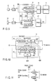
- the fundamental arrangement of the present invention is classified into four patterns, as shown in FIGS. 16A to 16D.
- a band division (BD) unit 1 divides a digital audio signal into frequency bands.
- a corrector 2 corrects a low-frequency audio signal after band division, and outputs the corrected signal to a low-frequency coder 3.
- a high-frequency coder 4 encodes a high-frequency audio signal after band division.
- a band division (BD) unit 1 outputs a low-frequency audio signal after band division to a low-frequency coder 3, and outputs a high-frequency audio signal to a high-frequency coder 4.
- a corrector 2 corrects high-frequency audio codes encoded by the high-frequency coder 4.
- a corrector 2 refers to a decoded signal output from a low-frequency decoder 5 upon correcting a low-frequency audio signal after band division.
- a corrector refers to a decoded signal output from a high-frequency decoder 6 upon correcting a high-frequency audio signal after band division.
- the correction process can be executed at a lower sampling rate than that before band division, and the data processing volume and memory size can be reduced.
- FIG. 1 is a block diagram showing the principal part of an audio codec according to the first embodiment.
- an apparatus of this embodiment is roughly comprised of a coding system for generating encoded audio data (TX) from a digital audio signal, and a reproduction system (decoding system) for decoding encoded audio data (RX) normally stored in a memory 15 to obtain an original audio signal.
- a coding system for generating encoded audio data (TX) from a digital audio signal
- decoding system for decoding encoded audio data (RX) normally stored in a memory 15 to obtain an original audio signal.
- the coding system has an A/D converter 11 for converting an audio signal input via a microphone 10 into a digital audio signal, a noise canceller 12, an encoder 13, and a multiplexer (data multiplexing unit) 14.
- the reproduction system has a loudspeaker 20, D/A converter 21, decoder (audio decoding circuit) 22, and demultiplexer 23. Note that the reproduction system shown in FIG. 1 is the same as the conventional system, and a description thereof will be omitted.
- the noise canceller 12, encoder 13, and multiplexer 14 are normally implemented by a digital signal processor (DSP).
- DSP digital signal processor
- the encoder 13 is an audio encoding circuit which executes compression coding of a digital audio signal using a predetermined algorithm (e.g., CELP), and generates encoded audio data.
- the encoder 13 is a wideband (e.g., AMR-WB) audio encoding circuit, and is separated into a low-frequency audio coder 130 and high-frequency audio coder (to be also referred to as an H coder hereinafter) 131.
- the multiplexer 14 converts encoded audio data generated by the encoder 13 to a format according to the characteristics of a transmission path, modem, error correction unit, or the like, and outputs the converted data to a memory 15.
- the noise suppression function of the noise canceller 12 is controlled to be enabled/disabled in accordance with a mode signal (HM) which sets the operation mode of the encoder 13.
- This mode signal is output from, e.g., a CPU 100 of a portable phone, and is used to determine whether or not to enable the high-frequency audio coder (H coder) 131.
- H coder high-frequency audio coder
- the low-frequency audio coder 130 has a module 200 including a downsample unit 201 and low-frequency coder (L coder) 202, and a noise canceller 203, as shown in FIG. 2.
- L coder low-frequency coder
- the downsample unit 201 downsamples to reduce the predetermined number of samples so as to execute a low-frequency process for the digital audio signal (VS) output from the A/D converter 11.
- the A/D converter 11 converts an audio signal input via the microphone 10 into a digital audio signal.
- H coder high-frequency audio coder
- the H coder 131 executes a coding process for a high-frequency audio signal.
- the noise canceller 203 skips a noise suppression process for the digital audio signal (VS) downsampled by the downsample unit 201, and directly passes it to the L coder 202.
- the downsampled digital audio signal (VS) has already undergone the noise suppression process by the noise canceller 12 of the previous stage.
- the outputs (encoded audio data) from the H coder 131 and L coder 202 are multiplexed by the multiplexer 14, and the multiplexed data is stored in the memory 15.
- the H coder 131 is disabled.
- the noise canceller 203 executes a noise suppression process for the digital audio signal (VS) downsampled by the downsample unit 201, and outputs the processed signal to the L coder 202.
- the L coder 202 generates low-frequency encoded audio data, and outputs it to the multiplexer 14.
- the noise canceller 12 inserted before the encoder 13 is also disabled. Therefore, the digital audio signal (VS) output from the A/D converter 11 passes through the noise canceller 12 and is supplied to the low-frequency audio coder 130 of the encoder 13.
- the noise canceller 203 is enabled to execute a noise suppression process for the digital audio signal (VS) downsampled by the downsample unit 201, and outputs the processed signal to the L coder 202. In this manner, the low-frequency audio coder 130 generates low-frequency encoded audio data from the low-frequency digital audio signal from which noise components has been suppressed.
- the noise canceller 12 inserted before the encoder 13 is disabled.
- the data processing volume and memory size in the DSP required to implement the noise canceller function can be reduced.
- the low-frequency audio coder 130 since the low-frequency noise canceller 203 is enabled, low-frequency encoded audio data can be generated without sound quality deterioration.
- the low-frequency noise canceller 203 executes a noise suppression process for the downsampled digital audio signal (the number of samples of which has been reduced).
- the data processing volume and memory size in the DSP required to implement the function of the noise canceller 203 can be more reduced than those upon enabling the high-frequency noise canceller 12.
- FIG. 3 is a block diagram showing the principal part of an audio codec according to the second embodiment.
- a coding system of this embodiment does not have any independent high-frequency noise canceller, and comprises an encoder 30 which has a low-frequency audio coder 300 including a low-frequency noise canceller (LNC) and a high-frequency audio coder 301 including a high-frequency noise canceller (HNC).
- LNC low-frequency noise canceller
- HNC high-frequency noise canceller
- the low-frequency audio coder 300 has a low-frequency coder (L coder) 400, downsample unit 401, and low-frequency noise canceller (LNC) 402, as shown in FIG. 4.
- the downsample unit 401 downsamples to reduce the predetermined number of samples so as to execute a low-frequency process for a digital audio signal (VS) output from the A/D converter 11.
- the LNC 402 executes a noise suppression process for mainly suppressing low-frequency ambient noise from the downsampled digital audio signal (VS).
- the L coder 400 generates low-frequency encoded audio data from the digital audio signal (downsampled signal) that has undergone noise suppression by the LNC 402, and outputs it to the multiplexer 14.
- the high-frequency audio coder 301 has a high-frequency coder (H coder) 500 and high-frequency noise canceller (HNC) 501.
- H coder high-frequency coder
- HNC high-frequency noise canceller
- the HNC 501 executes a noise suppression process for suppressing high-frequency ambient noise.
- the outputs (encoded audio data) from the HNC 501 and L coder 400 are multiplexed by the multiplexer 14, and the multiplexed data is stored in the memory 15.
- the H coder 500 is disabled (e.g., when the transmission rate is other than 23.85 kbps in AMR-WB).
- the low-frequency audio coder 300 alone is enabled to output encoded audio data as the output from the L coder 400 to the multiplexer 14.
- the high-frequency audio coder 301 is disabled, and the low-frequency audio coder 300 alone is enabled.
- the low-frequency audio coder 300 has a VAD (Voice Activity Detection) function of detecting, based on the digital audio signal (VS), whether the input speech period is a voiced or silence period. Upon detection of a silence period, the coder 300 outputs a predetermined flag (VADF) to the high-frequency audio coder 301.
- VAD Voice Activity Detection
- the output from the H coder 500 is encoded audio data mainly associated with the high-frequency gain of an audio signal.
- the HNC 501 is a high-frequency noise canceller which simply cancels noise by processing that encoded audio data.
- the L coder 400 includes the VAD function. More specifically, the L coder 400 has a VAD unit 50, voiced coder unit 51, and silence coder unit 52, as shown in FIG. 5A.
- the L coder 400 may have a VAD unit 50, voiced coder unit 51, silence coder unit 52, and switch unit 53, as shown in FIG. 5B.
- FIG. 6 is a block diagram showing a modification of the second embodiment.
- the operation of the HNC 501 in the high-frequency audio coder 301 is controlled in accordance with an operation mode signal (MS) from, e.g., a CPU 100 of a portable phone.
- the operation mode signal (MS) corresponds to a signal for setting a mode that processes an audio signal for, e.g., music.
- operation mode signal (MS) set by the CPU 100 is not limited to such specific mode for music, but may be used to set various other modes.
- FIG. 7 is a block diagram showing the principal part of an audio codec according to the third embodiment.
- FIGS. 8A and 8B are block diagrams showing the arrangement of a low-frequency audio coder 172 and low-frequency audio decoder 222 in FIG. 7.
- the noise canceller in the first embodiment is replaced by an echo canceller, a received audio signal (BR signal) input from the encoder 22 to a wideband echo canceller 16 is added, and an LBR signal input from the low-frequency audio decoder 222 to the low-frequency audio coder 172 (echo canceller 204) is added.
- BR signal received audio signal
- LBR signal input from the low-frequency audio decoder 222 to the low-frequency audio coder 172
- Either one of the echo cancellers 16 and 204 is enabled: when a high-frequency audio coder 171 is enabled (e.g., when the transmission rate is 23.85 kbps in AMR-WB), the echo canceller 16 alone is enabled; when the coder 171 is disabled (e.g., when the transmission rate is other than 23.85 kbps in AMR-WB), the echo canceller 204 alone is enabled. Therefore, when the high-frequency audio coder 171 is disabled, the data processing volume and memory size in the DSP required to implement the function of the echo canceller can be reduced.
- FIG. 9 is a block diagram showing the principal part of an audio codec according to the fourth embodiment.
- FIG. 10 is a block diagram showing the arrangement of an encoder 31 in FIG. 9.
- the noise canceller in the second embodiment is replaced by an echo canceller, an LBR signal input from a low-frequency audio decoder 222 to a low-frequency audio coder 310 (low-frequency echo canceller 403) is added, and an HBR signal input from a high-frequency audio decoder 221 to a high-frequency audio coder 311 (high-frequency echo canceller 502) is added.
- the high-frequency audio coder 500 When the high-frequency audio coder 500 is disabled (e.g., when the transmission rate is other than 23.85 kbps in AMR-WB), a high-frequency echo canceller 502 is disabled, and the low-frequency echo canceller 403 alone is enabled. Hence, when the high-frequency audio coder 500 is disabled, the data processing volume and memory size in the DSP required to implement the function of the echo canceller can be reduced.
- FIG. 11 is a block diagram showing a modification of the fourth embodiment.
- the operation of the HEC 502 in the high-frequency audio coder 311 is controlled in accordance with an operation mode signal (RBT) from, e.g., a CPU 100 of a portable phone. More specifically, the operation mode signal (RBT) sets a mode for processing a signal which has an extreme frequency deviation like a push tone, calling melody, alarm tone, or the like of a phone.
- RBT operation mode signal
- the HEC 502 and the LEC 403 stop learning operation.
- the operation mode signal (RBT) set from the CPU 100 is not limited to such specific mode for processing a push tone, calling melody, alarm tone, or the like, but may be used to set various other modes such as a coding mode or the like.
- FIGS. 12 to 15B are available.
- a low-frequency voice switch (LVS) 81 and high-frequency voice switch (HVS) 82 are combined.
- a high-frequency voice switch and low-frequency voice switch are combined.
- a high-frequency audio coder e.g., when the transmission rate is other than 23.85 kbps in AMR-WB
- only the low-frequency voice switch is enabled to reduce the data processing volume and memory size.
- the high-frequency audio coder 500 is inserted before the high-frequency noise canceller 501.
- the high-frequency noise canceller 501 may be inserted before the high-frequency audio coder 500.
- high-frequency audio coding is done after a noise cancellation process of a high-frequency signal.
- FIGS. 10 and 15A The same modification of the arrangement applies to FIGS. 10 and 15A.
- the high-frequency echo canceller 502 or a high-frequency attenuator may be inserted before the high-frequency audio coder 500.
- high-frequency audio coder 500 when the high-frequency audio coder 500 is enabled, high-frequency audio coding is done after a high-frequency echo cancellation process or a high-frequency voice switch process.
- the output signal from the high-frequency audio decoder 221 is used as a reference signal for the high-frequency echo canceller.
- an input signal of the high-frequency audio decoder 221 may be used as a reference signal.
- the high-frequency echo canceller uses a high-frequency signal power in an input bitstream of the high-frequency audio decoder 221 as a reference signal.
- an attenuator of the high-frequency voice switch 80 is inserted after the high-frequency audio decoder 221.
- the attenuator may be inserted before the high-frequency audio decoder 221.
- the high-frequency voice switch 80 executes a loss control process for a high-frequency signal power in an input bitstream of the high-frequency audio decoder 221.
- a loss controller of each voice switch comprises an attenuator, but may comprise an ON/OFF switch instead.
- the data processing volume and memory size required to implement the function of the noise canceller, echo canceller, or voice switch especially in the coding system can be reduced without deteriorating the sound quality.
- the audio coding processing efficiency can be consequently improved. More specifically, when an audio coding process for high-frequency audio signal components is skipped, and audio coding for low-frequency signal components is executed, a suppression process of noise or echo components contained in the low-frequency audio signal components can be executed. Therefore, in the arrangement that executes a noise or echo suppression process using the DSP, the data processing volume and memory size required to implement the function of the noise canceller, echo canceller, or voice switch can be reduced in the mode that skips the high-frequency audio coding process.
Abstract
Description
- The present invention generally relates to an audio signal processing apparatus which is applied to digital audio communications systems in the mobile communications field of, e.g., portable phones and the like and, more particularly, to a noise suppression function or echo suppression function in audio coding.
- In general, in the mobile communications field of, e.g., portable phones and the like, a digital audio communications system is applied. The digital audio communications system adopts audio coding (compression coding) to transmit compressed audio data.
- In the mobile communications field, a low-bit rate coding method called CELP (Code Excited Linear Prediction) is known as a typical audio coding method. Upon audio coding using such method, not only an audio signal but also an audio signal including noise components called high-frequency ambient noise is often encoded.
- As is known, when an audio signal containing noise and echo components is encoded, encoded audio data with poor quality is generated. For this reason, an audio coding circuit adopts a noise suppression circuit called a noise canceller so as to input only an audio signal from which noise components are suppressed. Also, an echo suppression circuit such as an echo canceller, voice switch, or the like is adopted to input an audio signal from which echo components are suppressed.
- The noise canceller determines a state wherein no audio signal is input, i.e., only an ambient noise signal is input. The noise canceller analyzes the feature of the ambient noise signal in that state. Then, the noise canceller suppresses noise components using the feature during a period in which an audio signal and noise components mix.
- The echo canceller determines a state wherein an audio signal reaches the receiving side but no audio signal is output from the sending side, i.e., a single-talk state of the receiving side. The echo canceller learns the returned acoustic characteristics from the receiving side to the sending side in that state. Then, the noise canceller suppresses echo components that mix in a signal on the sending side using the learned acoustic characteristics. The voice switch compares the signal powers of the receiving and sending sides, and suppresses echo components by inputting a loss to the lower power side.
- An audio coding scheme used in current portable phones is limited to the frequency band where an audio signal is mainly present. In recent years, a wideband coding scheme that implements audio coding in a frequency band wider than the audio signal frequency band is undergoing standardization. Such wideband coding scheme adopts CELP, and requires the noise canceller and echo canceller or voice switch.
- In an audio signal processor which uses a noise canceller and adopts a wideband coding scheme, a digital audio signal routed via the noise canceller is divided into high-frequency audio signal components which have less power as an audio signal and are not important in terms of information, and other low-frequency audio signal components. High-frequency audio signal components are not necessary in a given coding mode, and a method of removing such components from encoded audio data is known. As the coding mode, for example, AMR-WB (Adaptive Multi-Rate Wideband) codec specified by the 3GPP (3rd Generation Partnership Project) standard is available.
- In fact, in the coding mode that outputs encoded audio data of only low-frequency audio signal components (e.g., when the transmission rate is other than 23.85 kbps in AMR-WB), the noise canceller need not execute a noise suppression process for digital audio signal components of a full frequency band output from an A/
D converter 11, and need only execute a noise suppression process for low-frequency audio signal components. - In general, the noise canceller comprises a digital signal processor (DSP). Therefore, when the noise canceller executes digital audio signal components of the full frequency band, an excessive data processing volume and memory size are required for the DSP upon implementing the noise canceller function.
- The same applies to the echo canceller, and the audio signal processing efficiency are desirably improved by reducing the data processing volume and memory size required to implement an echo suppression function.
- Note that a method of reducing the calculation volume and necessary memory size has been proposed, in which echo cancellation of only low-frequency audio signal components without that of high-frequency audio signal components is executed (for example, see Jpn. Pat. Appln. KOKAI Publication No. 8-65211). However, with this method, high-frequency echo components remain unremoved.
- In accordance with one embodiment of the present invention, it is an object of the present invention to provide an audio coding apparatus which can improve the audio coding processing efficiency by reducing the data processing volume and memory size required for a noise canceller in audio coding.
- An apparatus for audio coding comprises a high-frequency audio coder which executes encoding for high-frequency audio components of a digital audio signal, a downsampling unit which lowers a sampling frequency of the same digital audio signal as the high-frequency audio coder processes, a noise suppressor which suppresses noise components contained in the signal processed by the downsampling unit, and a low-frequency audio coder which encodes the signal processed by the noise suppressor.
- This summary of the invention does not necessarily describe all necessary features so that the invention may also be a sub-combination of these described features.
- The invention can be more fully understood from the following detailed description when taken in conjunction with the accompanying drawings, in which:
- FIG. 1 is a block diagram showing the principal part of an audio codec according to the first embodiment of the present invention;
- FIG. 2 is a block diagram showing the arrangement of a low-frequency audio coder according to the first embodiment;
- FIG. 3 is a block diagram showing the principal part of an audio codec according to the second embodiment of the present invention;
- FIG. 4 is a block diagram showing the arrangement of an encoder according to the second embodiment;
- FIGS. 5A and 5B are block diagrams for explaining a VAD function according to the second embodiment;
- FIG. 6 is a block diagram showing a modification of the second embodiment;
- FIG. 7 is a block diagram showing the principal part of an audio codec according to the third embodiment of the present invention;
- FIGS. 8A and 8B are block diagrams showing the arrangement of a low-frequency audio coder according to the third embodiment;
- FIG. 9 is a block diagram showing the principal part of an audio codec according to the fourth embodiment of the present invention;
- FIG. 10 is a block diagram showing the arrangement of an encoder according to the fourth embodiment;
- FIG. 11 is a block diagram showing a modification of the fourth embodiment;
- FIG. 12 is a block diagram showing the principal part of an audio codec according to the fifth embodiment of the present invention;
- FIGS. 13A and 13B are block diagrams showing the arrangement of a low-frequency audio coder according to the fifth embodiment;
- FIG. 14 is a block diagram showing the principal part of an audio codec according to the sixth embodiment of the present invention;
- FIGS. 15A and 15B are block diagrams showing the arrangement of an encoder according to the sixth embodiment; and
- FIGS. 16A to 16D are block diagrams showing the fundamental arrangement of the present invention.
-
- The fundamental arrangement of the present invention is classified into four patterns, as shown in FIGS. 16A to 16D.
- In the first pattern, as shown in FIG. 16A, a band division (BD)
unit 1 divides a digital audio signal into frequency bands. Acorrector 2 corrects a low-frequency audio signal after band division, and outputs the corrected signal to a low-frequency coder 3. A high-frequency coder 4 encodes a high-frequency audio signal after band division. - In the second pattern, as shown in FIG. 16B, a band division (BD)
unit 1 outputs a low-frequency audio signal after band division to a low-frequency coder 3, and outputs a high-frequency audio signal to a high-frequency coder 4. Acorrector 2 corrects high-frequency audio codes encoded by the high-frequency coder 4. - In the third pattern, as shown in FIG. 16C, a
corrector 2 refers to a decoded signal output from a low-frequency decoder 5 upon correcting a low-frequency audio signal after band division. - In the fourth pattern, as shown in FIG. 16D, a corrector refers to a decoded signal output from a high-
frequency decoder 6 upon correcting a high-frequency audio signal after band division. - With these arrangement patterns, the correction process can be executed at a lower sampling rate than that before band division, and the data processing volume and memory size can be reduced.
- Preferred embodiments of the present invention will be described hereinafter with reference to the accompanying drawings.
- FIG. 1 is a block diagram showing the principal part of an audio codec according to the first embodiment.
- As shown in FIG. 1, an apparatus of this embodiment is roughly comprised of a coding system for generating encoded audio data (TX) from a digital audio signal, and a reproduction system (decoding system) for decoding encoded audio data (RX) normally stored in a
memory 15 to obtain an original audio signal. - The coding system has an A/
D converter 11 for converting an audio signal input via amicrophone 10 into a digital audio signal, anoise canceller 12, anencoder 13, and a multiplexer (data multiplexing unit) 14. On the other hand, the reproduction system has aloudspeaker 20, D/A converter 21, decoder (audio decoding circuit) 22, anddemultiplexer 23. Note that the reproduction system shown in FIG. 1 is the same as the conventional system, and a description thereof will be omitted. In the coding system, thenoise canceller 12,encoder 13, andmultiplexer 14 are normally implemented by a digital signal processor (DSP). - The
encoder 13 is an audio encoding circuit which executes compression coding of a digital audio signal using a predetermined algorithm (e.g., CELP), and generates encoded audio data. Theencoder 13 is a wideband (e.g., AMR-WB) audio encoding circuit, and is separated into a low-frequency audio coder 130 and high-frequency audio coder (to be also referred to as an H coder hereinafter) 131. Themultiplexer 14 converts encoded audio data generated by theencoder 13 to a format according to the characteristics of a transmission path, modem, error correction unit, or the like, and outputs the converted data to amemory 15. - The noise suppression function of the
noise canceller 12 is controlled to be enabled/disabled in accordance with a mode signal (HM) which sets the operation mode of theencoder 13. This mode signal is output from, e.g., a CPU 100 of a portable phone, and is used to determine whether or not to enable the high-frequency audio coder (H coder) 131. Assume that theH coder 131 is enabled when "HM = 1" (e.g., when the transmission rate is 23.85 kbps in AMR-WB), and theH coder 131 is disabled when "HM = 0" (e.g., when the transmission rate is other than 23.85 kbps in AMR-WB), for the sake of simplicity. - The
noise canceller 12 is enabled when "HM = 1", and suppresses noise components of the digital audio signal output from the A/D converter 11. On the other hand, thenoise canceller 12 skips a noise suppression process, and allows the digital audio signal (VS) output from the A/D converter 11 to pass through it, when "HM = 0". - The low-
frequency audio coder 130 has amodule 200 including adownsample unit 201 and low-frequency coder (L coder) 202, and anoise canceller 203, as shown in FIG. 2. - The
downsample unit 201 downsamples to reduce the predetermined number of samples so as to execute a low-frequency process for the digital audio signal (VS) output from the A/D converter 11. - The
noise canceller 203 executes a noise suppression process for the digital audio signal (VS) downsampled by thedownsample unit 201, and outputs the processed signal to theL coder 202, when "HM = 0". On the other hand, thenoise canceller 203 skips a noise suppression process for the digital audio signal (VS) downsampled by thedownsample unit 201, and directly passes it to theL coder 202, when "HM = 1". - The operation of the coding system of this embodiment will be described below with reference to FIGS. 1 and 2.
- For example, the CPU of a portable phone outputs a mode signal HM to set the operation mode (HM = 1/0) of the
encoder 13. The A/D converter 11 converts an audio signal input via themicrophone 10 into a digital audio signal. - Assume that the operation mode that enables the high-frequency audio coder (H coder) 131 (e.g., when the transmission rate is 23.85 kbps in AMR-WB) is set (HM = 1). The
noise canceller 12 is enabled when "HM = 1", suppresses noise components of the digital audio signal output from the A/D converter 11, and outputs that signal to theencoder 13. - In the
encoder 13, theH coder 131 executes a coding process for a high-frequency audio signal. On the other hand, in the low-frequency audio coder 130, when "HM = 1", thenoise canceller 203 skips a noise suppression process for the digital audio signal (VS) downsampled by thedownsample unit 201, and directly passes it to theL coder 202. Note that the downsampled digital audio signal (VS) has already undergone the noise suppression process by thenoise canceller 12 of the previous stage. The outputs (encoded audio data) from theH coder 131 andL coder 202 are multiplexed by themultiplexer 14, and the multiplexed data is stored in thememory 15. - On the other hand, assume that the operation mode that disables the high-frequency audio coder (H coder) 131 (e.g., when the transmission rate is other than 23.85 kbps in AMR-WB) is set (HM = 0). When "HM = 0", the
noise canceller 12 skips a noise suppression process, and allows the digital audio signal (VS) output from the A/D converter 11 to pass through it. TheH coder 131 is disabled. - In the low-
frequency audio coder 130, when "HM = 0", thenoise canceller 203 executes a noise suppression process for the digital audio signal (VS) downsampled by thedownsample unit 201, and outputs the processed signal to theL coder 202. TheL coder 202 generates low-frequency encoded audio data, and outputs it to themultiplexer 14. - As described above, according to this embodiment, when the operation mode of the coding system disables the H coder 131 (HM = 0), the
noise canceller 12 inserted before theencoder 13 is also disabled. Therefore, the digital audio signal (VS) output from the A/D converter 11 passes through thenoise canceller 12 and is supplied to the low-frequency audio coder 130 of theencoder 13. - In the low-
frequency audio coder 130, when "HM = 0", thenoise canceller 203 is enabled to execute a noise suppression process for the digital audio signal (VS) downsampled by thedownsample unit 201, and outputs the processed signal to theL coder 202. In this manner, the low-frequency audio coder 130 generates low-frequency encoded audio data from the low-frequency digital audio signal from which noise components has been suppressed. - Therefore, in the operation mode that disables the high-
frequency audio coder 131, thenoise canceller 12 inserted before theencoder 13 is disabled. Hence, the data processing volume and memory size in the DSP required to implement the noise canceller function can be reduced. On the other hand, in the low-frequency audio coder 130, since the low-frequency noise canceller 203 is enabled, low-frequency encoded audio data can be generated without sound quality deterioration. In this case, the low-frequency noise canceller 203 executes a noise suppression process for the downsampled digital audio signal (the number of samples of which has been reduced). Hence, the data processing volume and memory size in the DSP required to implement the function of thenoise canceller 203 can be more reduced than those upon enabling the high-frequency noise canceller 12. - FIG. 3 is a block diagram showing the principal part of an audio codec according to the second embodiment.
- A coding system of this embodiment does not have any independent high-frequency noise canceller, and comprises an
encoder 30 which has a low-frequency audio coder 300 including a low-frequency noise canceller (LNC) and a high-frequency audio coder 301 including a high-frequency noise canceller (HNC). Note that the reproduction system (decoding system) is the same as that in the first embodiment (see FIG. 1), and a description thereof will be omitted. - In the
encoder 30, the low-frequency audio coder 300 has a low-frequency coder (L coder) 400,downsample unit 401, and low-frequency noise canceller (LNC) 402, as shown in FIG. 4. Thedownsample unit 401 downsamples to reduce the predetermined number of samples so as to execute a low-frequency process for a digital audio signal (VS) output from the A/D converter 11. TheLNC 402 executes a noise suppression process for mainly suppressing low-frequency ambient noise from the downsampled digital audio signal (VS). TheL coder 400 generates low-frequency encoded audio data from the digital audio signal (downsampled signal) that has undergone noise suppression by theLNC 402, and outputs it to themultiplexer 14. - On the other hand, the high-
frequency audio coder 301 has a high-frequency coder (H coder) 500 and high-frequency noise canceller (HNC) 501. Whether or not theH coder 500 is enabled is determined in accordance with an operation mode (HM = 1/0) set by the aforementioned mode signal HM. That is, when "HM = 1", theH coder 500 is enabled (e.g., when the transmission rate is 23.85 kbps in AMR-WB), and executes a coding process for a high-frequency audio signal of the digital audio signal (VS) output from the A/D converter 11. - The
HNC 501 executes a noise suppression process for suppressing high-frequency ambient noise. The outputs (encoded audio data) from theHNC 501 andL coder 400 are multiplexed by themultiplexer 14, and the multiplexed data is stored in thememory 15. - When "HM = 0", the
H coder 500 is disabled (e.g., when the transmission rate is other than 23.85 kbps in AMR-WB). In this operation mode, the low-frequency audio coder 300 alone is enabled to output encoded audio data as the output from theL coder 400 to themultiplexer 14. - As described above, according to this embodiment, when the operation mode of the coding system disables the H coder 500 (HM = 0), the high-
frequency audio coder 301 is disabled, and the low-frequency audio coder 300 alone is enabled. Hence, when "HM = 0", only theLNC 402 included in the low-frequency audio coder 300 is enabled to execute a noise suppression process for the digital audio signal (VS) downsampled by thedownsample unit 401. Therefore, in the operation mode that disables the high-frequency audio coder 301, the data processing volume and memory size in the DSP required to implement the function of the noise canceller can be reduced. - The low-
frequency audio coder 300 has a VAD (Voice Activity Detection) function of detecting, based on the digital audio signal (VS), whether the input speech period is a voiced or silence period. Upon detection of a silence period, thecoder 300 outputs a predetermined flag (VADF) to the high-frequency audio coder 301. - In the high-
frequency audio coder 301, the output from theH coder 500 is encoded audio data mainly associated with the high-frequency gain of an audio signal. TheHNC 501 is a high-frequency noise canceller which simply cancels noise by processing that encoded audio data. - Upon detection of a silence period (VADF = 0), the
HNC 501 determines that the high-frequency gain is that of a noise signal (noise), subtracts a value corresponding to the gain from the output signal from theH coder 500, and outputs the difference to themultiplexer 14. On the other hand, upon detection of a voiced period (VADF = 1), theHNC 501 subtracts the value, which is subtracted in the silence period (VADF = 0) from the input of theH coder 500, and outputs the difference to themultiplexer 14. - In the low-
frequency audio coder 300, theL coder 400 includes the VAD function. More specifically, theL coder 400 has aVAD unit 50, voicedcoder unit 51, andsilence coder unit 52, as shown in FIG. 5A. Thesilence coder unit 52 is enabled when theVAD unit 50 outputs a flag (VADF = 0) indicating a silence period. The voicedcoder unit 51 is enabled when theVAD unit 50 outputs a flag (VADF = 1) indicating a voiced period. TheVAD unit 50 outputs the flag (VADF = 1/0) to theHNC 501 of the high-frequency audio coder 301. - The
L coder 400 may have aVAD unit 50, voicedcoder unit 51,silence coder unit 52, and switchunit 53, as shown in FIG. 5B. Theswitch unit 53 transfers the digital audio signal (VS) to thesilence coder unit 52 when theVAD unit 50 outputs a flag (VADF = 0) indicating a silence period. Theswitch unit 53 transfers the digital audio signal (VS) to the voicedcoder unit 51 when theVAD unit 50 outputs a flag (VADF = 1) indicating a voiced period. TheVAD unit 50 outputs the flag (VADF = 1/0) to theHNC 501 of the high-frequency audio coder 301. - FIG. 6 is a block diagram showing a modification of the second embodiment.
- In an arrangement of this modification, the operation of the
HNC 501 in the high-frequency audio coder 301 is controlled in accordance with an operation mode signal (MS) from, e.g., a CPU 100 of a portable phone. More specifically, the operation mode signal (MS) corresponds to a signal for setting a mode that processes an audio signal for, e.g., music. - In the high-
frequency audio coder 301, upon executing a high-frequency coding process for an audio signal for music coming from the CPU 100, theHNC 501 operates in accordance with the operation mode signal (MS = 1), and executes a high-frequency noise suppression process effective for music. - Note that the operation mode signal (MS) set by the CPU 100 is not limited to such specific mode for music, but may be used to set various other modes.
- FIG. 7 is a block diagram showing the principal part of an audio codec according to the third embodiment. FIGS. 8A and 8B are block diagrams showing the arrangement of a low-
frequency audio coder 172 and low-frequency audio decoder 222 in FIG. 7. - In this embodiment, as can be seen from comparison between FIGS. 1 and 7 and that between FIGS. 2 and 8A, the noise canceller in the first embodiment is replaced by an echo canceller, a received audio signal (BR signal) input from the
encoder 22 to awideband echo canceller 16 is added, and an LBR signal input from the low-frequency audio decoder 222 to the low-frequency audio coder 172 (echo canceller 204) is added. - Either one of the
echo cancellers frequency audio coder 171 is enabled (e.g., when the transmission rate is 23.85 kbps in AMR-WB), theecho canceller 16 alone is enabled; when thecoder 171 is disabled (e.g., when the transmission rate is other than 23.85 kbps in AMR-WB), theecho canceller 204 alone is enabled. Therefore, when the high-frequency audio coder 171 is disabled, the data processing volume and memory size in the DSP required to implement the function of the echo canceller can be reduced. - FIG. 9 is a block diagram showing the principal part of an audio codec according to the fourth embodiment. FIG. 10 is a block diagram showing the arrangement of an
encoder 31 in FIG. 9. - In this embodiment, as can be seen from comparison between FIGS. 3 and 9 and that between FIGS. 4 and 10, the noise canceller in the second embodiment is replaced by an echo canceller, an LBR signal input from a low-
frequency audio decoder 222 to a low-frequency audio coder 310 (low-frequency echo canceller 403) is added, and an HBR signal input from a high-frequency audio decoder 221 to a high-frequency audio coder 311 (high-frequency echo canceller 502) is added. - When the high-
frequency audio coder 500 is disabled (e.g., when the transmission rate is other than 23.85 kbps in AMR-WB), a high-frequency echo canceller 502 is disabled, and the low-frequency echo canceller 403 alone is enabled. Hence, when the high-frequency audio coder 500 is disabled, the data processing volume and memory size in the DSP required to implement the function of the echo canceller can be reduced. - FIG. 11 is a block diagram showing a modification of the fourth embodiment.
- In an arrangement of this modification, the operation of the
HEC 502 in the high-frequency audio coder 311 is controlled in accordance with an operation mode signal (RBT) from, e.g., a CPU 100 of a portable phone. More specifically, the operation mode signal (RBT) sets a mode for processing a signal which has an extreme frequency deviation like a push tone, calling melody, alarm tone, or the like of a phone. - The
HEC 502 operates in accordance with the operation mode signal (RBT = 1).TheHEC 502 and theLEC 403 stop learning operation. - Note that the operation mode signal (RBT) set from the CPU 100 is not limited to such specific mode for processing a push tone, calling melody, alarm tone, or the like, but may be used to set various other modes such as a coding mode or the like.
- Also, by replacing the echo cancellers in FIGS. 7 to 10 by voice switches, embodiments shown in FIGS. 12 to 15B are available. In FIGS. 12, 13A, and 13B, a low-frequency voice switch (LVS) 81 and high-frequency voice switch (HVS) 82 are combined.
- In FIGS. 14, 15A, and 15B, a high-frequency voice switch and low-frequency voice switch are combined. In either embodiment, when a high-frequency audio coder is disabled (e.g., when the transmission rate is other than 23.85 kbps in AMR-WB), only the low-frequency voice switch is enabled to reduce the data processing volume and memory size.
- In FIG. 4, the high-
frequency audio coder 500 is inserted before the high-frequency noise canceller 501. Alternatively, the high-frequency noise canceller 501 may be inserted before the high-frequency audio coder 500. In this case, when the high-frequency audio coder 500 is enabled, high-frequency audio coding is done after a noise cancellation process of a high-frequency signal. The same modification of the arrangement applies to FIGS. 10 and 15A. - That is, the high-
frequency echo canceller 502 or a high-frequency attenuator may be inserted before the high-frequency audio coder 500. In this case, when the high-frequency audio coder 500 is enabled, high-frequency audio coding is done after a high-frequency echo cancellation process or a high-frequency voice switch process. - In FIG. 9, the output signal from the high-
frequency audio decoder 221 is used as a reference signal for the high-frequency echo canceller. Alternatively, an input signal of the high-frequency audio decoder 221 may be used as a reference signal. In this case, the high-frequency echo canceller uses a high-frequency signal power in an input bitstream of the high-frequency audio decoder 221 as a reference signal. - In FIG. 14, an attenuator of the high-
frequency voice switch 80 is inserted after the high-frequency audio decoder 221. Alternatively, the attenuator may be inserted before the high-frequency audio decoder 221. In this case, the high-frequency voice switch 80 executes a loss control process for a high-frequency signal power in an input bitstream of the high-frequency audio decoder 221. - In FIGS. 12 to 15, a loss controller of each voice switch comprises an attenuator, but may comprise an ON/OFF switch instead.
- As described above, according to the above embodiments, especially in an audio codec which has a wideband audio coding circuit (encoder) and one or more of a noise canceller, echo canceller, and voice switch, the data processing volume and memory size required to implement the function of the noise canceller, echo canceller, or voice switch especially in the coding system can be reduced without deteriorating the sound quality.
- Therefore, the audio coding processing efficiency can be consequently improved. More specifically, when an audio coding process for high-frequency audio signal components is skipped, and audio coding for low-frequency signal components is executed, a suppression process of noise or echo components contained in the low-frequency audio signal components can be executed. Therefore, in the arrangement that executes a noise or echo suppression process using the DSP, the data processing volume and memory size required to implement the function of the noise canceller, echo canceller, or voice switch can be reduced in the mode that skips the high-frequency audio coding process.
Claims (14)
- An apparatus for audio coding, characterized by comprising:a high-frequency audio coder (131) which encodes high-frequency components of a digital audio signal;a downsampling unit (201) which lowers a sampling frequency of the same digital audio signal as the high-frequency audio coder processes;a noise suppressor (203) which suppresses noise components contained in the signal processed by the downsampling unit (201); anda low-frequency audio coder (202) which encodes the signal processed by the noise suppressor (203).
- An apparatus according to claim 1, characterized by further comprising a second noise suppressor (12) which suppresses high-frequency noise components of the digital audio signal before the digital audio signal is processed by the high-frequency audio coder (131) and the downsampling unit (201).
- An apparatus according to claim 1, characterized in that when the high-frequency audio coder (131) is disabled, the second noise suppressor (12) skips suppression of the high-frequency noise components and allows the digital audio signal to pass through it.
- An apparatus according to claim 1, characterized in that when the high-frequency audio coder (131) is enabled, the noise suppressor (203) skips suppression of the low-frequency noise components, and inputs the digital audio signal to the low-frequency audio decoder (202).
- An apparatus according to claim 1, characterized in that the high-frequency audio coder (301) includes a high-frequency noise suppressor (501) which suppresses noise components contained in the encoded high-frequency audio signal.
- An apparatus according to claim 1, characterized in that the low-frequency audio coder (300) identifies a silence signal from the digital audio signal, and outputs a signal indicating the silence signal to the high-frequency audio coder (301),
the high-frequency audio coder (301) includes a high-frequency noise suppressor (501) which suppresses noise components contained in the encoded high-frequency audio signal, and
the high-frequency noise suppressor (501) subtracts a value corresponding to a gain of the silence signal from the encoded high-frequency audio signal in accordance with the silence signal. - An apparatus according to claim 1, characterized in that the high-frequency audio coder (301) includes a high-frequency noise suppressor (501) which suppresses noise components contained in the encoded high-frequency audio signal, and
the apparatus further comprises:a CPU (100) which controls to enable or disable a function of the high-frequency noise suppressor (501) in accordance with a coding mode of the digital audio signal. - An apparatus for audio coding, characterized by comprising:a first echo suppressor (16) which suppresses high-frequency echo components of a digital audio signal;a high-frequency audio coder (171) which encodes the signal processed by the first echo suppressor (16);a downsampling unit (201) which lowers a sampling frequency of the same digital audio signal as the first echo suppressor processes;a second echo suppressor (204) which suppresses echo components contained in the signal processed by the downsampling unit (201); anda low-frequency audio coder (202) which encodes the signal processed by the second echo suppressor (204) .
- An apparatus according to claim 8, characterized in that when the high-frequency audio coder (171) is disabled, the first echo suppressor (16) skips suppression of the echo components and allows the digital audio signal to pass through it.
- An apparatus according to claim 8, characterized in that when the high-frequency audio coder (171) is enabled, the second echo suppressor (204) skips suppression of the echo components, and inputs the digital audio signal to the low-frequency audio decoder (202) .
- An apparatus according to claim 8, characterized in that the high-frequency audio coder (311) includes a high-frequency echo suppressor (502) which suppresses echo components contained in the encoded high-frequency audio signal.
- An apparatus according to claim 8, characterized in that the high-frequency audio coder (311) includes a high-frequency echo suppressor (502) which suppresses echo components contained in the encoded high-frequency audio signal, and
the apparatus further comprises:a CPU (100) which controls to enable or disable a function of the second high-frequency echo suppressor (502) in accordance with a coding mode of the digital audio signal. - A method of audio coding, characterized by comprising:encoding high-frequency components of a digital audio signal;downsampling the digital audio signal being not encoded;suppressing noise components contained in the downsampled digital audio signal; andencoding the digital audio signal the noise components of which are suppressed.
- A method of audio coding, characterized by comprising:suppressing echo components contained in a high-frequency range of a digital audio signal;encoding the high-frequency digital audio signal the echo components of which are suppressed;downsampling the digital audio signal being not suppressed;suppressing echo components of the downsampled digital audio signal; andencoding a low-frequency digital audio signal the echo components of which are suppressed.
Priority Applications (3)
| Application Number | Priority Date | Filing Date | Title |
|---|---|---|---|
| US10/654,400 US7443978B2 (en) | 2003-09-04 | 2003-09-04 | Method and apparatus for audio coding with noise suppression |
| EP03019690A EP1515307B1 (en) | 2003-09-04 | 2003-09-09 | Method and apparatus for audio coding with noise suppression |
| DE60309468T DE60309468T2 (en) | 2003-09-09 | 2003-09-09 | Method and apparatus for audio coding with noise reduction |
Applications Claiming Priority (2)
| Application Number | Priority Date | Filing Date | Title |
|---|---|---|---|
| US10/654,400 US7443978B2 (en) | 2003-09-04 | 2003-09-04 | Method and apparatus for audio coding with noise suppression |
| EP03019690A EP1515307B1 (en) | 2003-09-04 | 2003-09-09 | Method and apparatus for audio coding with noise suppression |
Publications (2)
| Publication Number | Publication Date |
|---|---|
| EP1515307A1 true EP1515307A1 (en) | 2005-03-16 |
| EP1515307B1 EP1515307B1 (en) | 2006-11-02 |
Family
ID=34524694
Family Applications (1)
| Application Number | Title | Priority Date | Filing Date |
|---|---|---|---|
| EP03019690A Expired - Lifetime EP1515307B1 (en) | 2003-09-04 | 2003-09-09 | Method and apparatus for audio coding with noise suppression |
Country Status (2)
| Country | Link |
|---|---|
| US (1) | US7443978B2 (en) |
| EP (1) | EP1515307B1 (en) |
Cited By (1)
| Publication number | Priority date | Publication date | Assignee | Title |
|---|---|---|---|---|
| CN101277331B (en) * | 2007-03-27 | 2011-10-05 | 索尼株式会社 | Sound reproducing device and sound reproduction method |
Families Citing this family (14)
| Publication number | Priority date | Publication date | Assignee | Title |
|---|---|---|---|---|
| US7333475B2 (en) * | 2002-09-27 | 2008-02-19 | Broadcom Corporation | Switchboard for multiple data rate communication system |
| US7987095B2 (en) * | 2002-09-27 | 2011-07-26 | Broadcom Corporation | Method and system for dual mode subband acoustic echo canceller with integrated noise suppression |
| US7574353B2 (en) * | 2004-11-18 | 2009-08-11 | Lsi Logic Corporation | Transmit/receive data paths for voice-over-internet (VoIP) communication systems |
| KR101168095B1 (en) * | 2005-11-30 | 2012-07-24 | 삼성전자주식회사 | Method and apparatus for communication using tx/rx fifo in a wide-band stereo codec interface |
| FR2897733A1 (en) * | 2006-02-20 | 2007-08-24 | France Telecom | Echo discriminating and attenuating method for hierarchical coder-decoder, involves attenuating echoes based on initial processing in discriminated low energy zone, and inhibiting attenuation of echoes in false alarm zone |
| US20100017197A1 (en) * | 2006-11-02 | 2010-01-21 | Panasonic Corporation | Voice coding device, voice decoding device and their methods |
| US8982744B2 (en) * | 2007-06-06 | 2015-03-17 | Broadcom Corporation | Method and system for a subband acoustic echo canceller with integrated voice activity detection |
| MX2011010870A (en) | 2009-04-14 | 2012-04-20 | En Technology Corp | Digital audio communication and control in a live performance venue. |
| US20130066638A1 (en) * | 2011-09-09 | 2013-03-14 | Qnx Software Systems Limited | Echo Cancelling-Codec |
| FR2992766A1 (en) * | 2012-06-29 | 2014-01-03 | France Telecom | EFFECTIVE MITIGATION OF PRE-ECHO IN AUDIONUMERIC SIGNAL |
| US9269368B2 (en) * | 2013-03-15 | 2016-02-23 | Broadcom Corporation | Speaker-identification-assisted uplink speech processing systems and methods |
| US10186276B2 (en) * | 2015-09-25 | 2019-01-22 | Qualcomm Incorporated | Adaptive noise suppression for super wideband music |
| US11257476B2 (en) * | 2018-03-16 | 2022-02-22 | Sony Corporation | Signal processing apparatus and signal processing method |
| US11031026B2 (en) * | 2018-12-13 | 2021-06-08 | Qualcomm Incorporated | Acoustic echo cancellation during playback of encoded audio |
Citations (6)
| Publication number | Priority date | Publication date | Assignee | Title |
|---|---|---|---|---|
| JPH0865211A (en) * | 1994-08-17 | 1996-03-08 | Ricoh Co Ltd | Echo canceler |
| US6144937A (en) * | 1997-07-23 | 2000-11-07 | Texas Instruments Incorporated | Noise suppression of speech by signal processing including applying a transform to time domain input sequences of digital signals representing audio information |
| EP1154408A2 (en) * | 2000-05-10 | 2001-11-14 | Kabushiki Kaisha Toshiba | Multimode speech coding and noise reduction |
| US20020072899A1 (en) * | 1999-12-21 | 2002-06-13 | Erdal Paksoy | Sub-band speech coding system |
| US6408269B1 (en) * | 1999-03-03 | 2002-06-18 | Industrial Technology Research Institute | Frame-based subband Kalman filtering method and apparatus for speech enhancement |
| US20020097807A1 (en) * | 2001-01-19 | 2002-07-25 | Gerrits Andreas Johannes | Wideband signal transmission system |
Family Cites Families (2)
| Publication number | Priority date | Publication date | Assignee | Title |
|---|---|---|---|---|
| US5561668A (en) | 1995-07-06 | 1996-10-01 | Coherent Communications Systems Corp. | Echo canceler with subband attenuation and noise injection control |
| US6526139B1 (en) * | 1999-11-03 | 2003-02-25 | Tellabs Operations, Inc. | Consolidated noise injection in a voice processing system |
-
2003
- 2003-09-04 US US10/654,400 patent/US7443978B2/en active Active
- 2003-09-09 EP EP03019690A patent/EP1515307B1/en not_active Expired - Lifetime
Patent Citations (6)
| Publication number | Priority date | Publication date | Assignee | Title |
|---|---|---|---|---|
| JPH0865211A (en) * | 1994-08-17 | 1996-03-08 | Ricoh Co Ltd | Echo canceler |
| US6144937A (en) * | 1997-07-23 | 2000-11-07 | Texas Instruments Incorporated | Noise suppression of speech by signal processing including applying a transform to time domain input sequences of digital signals representing audio information |
| US6408269B1 (en) * | 1999-03-03 | 2002-06-18 | Industrial Technology Research Institute | Frame-based subband Kalman filtering method and apparatus for speech enhancement |
| US20020072899A1 (en) * | 1999-12-21 | 2002-06-13 | Erdal Paksoy | Sub-band speech coding system |
| EP1154408A2 (en) * | 2000-05-10 | 2001-11-14 | Kabushiki Kaisha Toshiba | Multimode speech coding and noise reduction |
| US20020097807A1 (en) * | 2001-01-19 | 2002-07-25 | Gerrits Andreas Johannes | Wideband signal transmission system |
Cited By (1)
| Publication number | Priority date | Publication date | Assignee | Title |
|---|---|---|---|---|
| CN101277331B (en) * | 2007-03-27 | 2011-10-05 | 索尼株式会社 | Sound reproducing device and sound reproduction method |
Also Published As
| Publication number | Publication date |
|---|---|
| US7443978B2 (en) | 2008-10-28 |
| US20050055116A1 (en) | 2005-03-10 |
| EP1515307B1 (en) | 2006-11-02 |
Similar Documents
| Publication | Publication Date | Title |
|---|---|---|
| EP1346553B1 (en) | Audio signal quality enhancement in a digital network | |
| US7058574B2 (en) | Signal processing apparatus and mobile radio communication terminal | |
| JP4897173B2 (en) | Noise suppression | |
| US7443978B2 (en) | Method and apparatus for audio coding with noise suppression | |
| JP5065687B2 (en) | Audio data processing device and terminal device | |
| AU2017405291B2 (en) | Method and apparatus for processing speech signal adaptive to noise environment | |
| US6122531A (en) | Method for selectively including leading fricative sounds in a portable communication device operated in a speakerphone mode | |
| JPH11126098A (en) | Voice synthesizing method and device therefor, band width expanding method and device therefor | |
| JPH02288520A (en) | Voice encoding/decoding system with background sound reproducing function | |
| US20030065507A1 (en) | Network unit and a method for modifying a digital signal in the coded domain | |
| WO2001002929A2 (en) | Coded domain noise control | |
| JP3854188B2 (en) | Audio signal processing device | |
| JP3727800B2 (en) | Echo canceller and voice communication apparatus provided with the echo canceller | |
| JP2004053763A (en) | Speech encoding transmission system of multipoint controller | |
| JP3316945B2 (en) | Transmission error compensator | |
| JP3355585B2 (en) | Echo cancellation method | |
| JP2002006898A (en) | Method and device for noise reduction | |
| JP2002041100A (en) | Digital voice processing device | |
| JPH08130515A (en) | Voice coding device | |
| JP3432319B2 (en) | Voice communication device | |
| JP3163567B2 (en) | Voice coded communication system and apparatus therefor | |
| JP2002198870A (en) | Echo processing device | |
| JPH08139688A (en) | Voice encoding device | |
| JP2000101683A (en) | Voice communication equipment | |
| JPH10307598A (en) | Voice encoding transmitter |
Legal Events
| Date | Code | Title | Description |
|---|---|---|---|
| PUAI | Public reference made under article 153(3) epc to a published international application that has entered the european phase |
Free format text: ORIGINAL CODE: 0009012 |
|
| 17P | Request for examination filed |
Effective date: 20030909 |
|
| AK | Designated contracting states |
Kind code of ref document: A1 Designated state(s): AT BE BG CH CY CZ DE DK EE ES FI FR GB GR HU IE IT LI LU MC NL PT RO SE SI SK TR |
|
| AX | Request for extension of the european patent |
Extension state: AL LT LV MK |
|
| AKX | Designation fees paid |
Designated state(s): DE FR GB |
|
| GRAP | Despatch of communication of intention to grant a patent |
Free format text: ORIGINAL CODE: EPIDOSNIGR1 |
|
| GRAS | Grant fee paid |
Free format text: ORIGINAL CODE: EPIDOSNIGR3 |
|
| GRAA | (expected) grant |
Free format text: ORIGINAL CODE: 0009210 |
|
| AK | Designated contracting states |
Kind code of ref document: B1 Designated state(s): DE FR GB |
|
| REG | Reference to a national code |
Ref country code: GB Ref legal event code: FG4D |
|
| REF | Corresponds to: |
Ref document number: 60309468 Country of ref document: DE Date of ref document: 20061214 Kind code of ref document: P |
|
| ET | Fr: translation filed | ||
| PLBE | No opposition filed within time limit |
Free format text: ORIGINAL CODE: 0009261 |
|
| STAA | Information on the status of an ep patent application or granted ep patent |
Free format text: STATUS: NO OPPOSITION FILED WITHIN TIME LIMIT |
|
| 26N | No opposition filed |
Effective date: 20070803 |
|
| REG | Reference to a national code |
Ref country code: FR Ref legal event code: PLFP Year of fee payment: 14 |
|
| REG | Reference to a national code |
Ref country code: FR Ref legal event code: PLFP Year of fee payment: 15 |
|
| REG | Reference to a national code |
Ref country code: FR Ref legal event code: PLFP Year of fee payment: 16 |
|
| PGFP | Annual fee paid to national office [announced via postgrant information from national office to epo] |
Ref country code: GB Payment date: 20220721 Year of fee payment: 20 Ref country code: DE Payment date: 20220609 Year of fee payment: 20 |
|
| PGFP | Annual fee paid to national office [announced via postgrant information from national office to epo] |
Ref country code: FR Payment date: 20220709 Year of fee payment: 20 |
|
| REG | Reference to a national code |
Ref country code: DE Ref legal event code: R071 Ref document number: 60309468 Country of ref document: DE |
|
| REG | Reference to a national code |
Ref country code: GB Ref legal event code: PE20 Expiry date: 20230908 |
|
| PG25 | Lapsed in a contracting state [announced via postgrant information from national office to epo] |
Ref country code: GB Free format text: LAPSE BECAUSE OF EXPIRATION OF PROTECTION Effective date: 20230908 |