Technical Field
This invention relates to an optical mixer in which a hollow motor is used to
rotate an optical mixing plate at a peripheral speed of at least 1800 times per minute
relative to the laser beam diameter to convert coherent light into virtually incoherent
light.
Background of the Invention
A method to simply pass a laser beam through a rotating diffusion plate is
conventionally used in laboratories to solve problems caused by coherence that are
unique to the laser beam. This method, however, is unable to remove speckle
patterns from the excellent coherence unique to the laser beam. The laser beam is
merely homogenized.
In 1977 Hard et al made a laser beam pass a round optical glass-made wedge
that was rotating at 2500 rpm and the variations in wedge thickness were
immediately reflected on the length of the light path. Their method solved many
problems associated with coherence unique to the laser beam and served to improve
differential interference contrast images.
Presently, an optical fiber lightguide is set between the laser beam and
microscope, and the length of the light path is modified by vibrating the lightguide
using a piezoelectric element or speaker-vibrated membrane. When a lightguide
(optical fibers) is vibrated, the laser beam becomes incoherent in terms of time at a
frequencies lower than the vibration frequency.
However, the above system that vibrates a lightguide set between laser beam
and microscope to change the length of the light path is not an optical component
easily built into optical systems. A unit incorporating such a system is not compact
and the cost is rather high.
When a laser beam is used in illumination systems, the coherence of the laser
beam has the effect of generating a complex diffraction pattern due to interference
of the reflected light from all surfaces, dirty optical elements, and scattered light
from damaged optical parts.
Even fluorescence of a different wavelength from excitation light used for
illumination (assumed to be an incoherent light) like one on a fluorescence
microscope is not immune from this influence. Strong interference fringes caused by
excitation light for illumination give rise to striped patterns even in the fluorescent
images. This problem is experienced in a wide range of microscopic observations.
The coherence of laser beams, in particular, is very strong and the coherence-related
problems have basically remained unsolved. This is the reason why laser beams are
not used much as bright light sources of excellent monochromaticity at present.
This invention intends to solve these conventional problems by providing an
optical mixer that converts the coherence of the laser beams into virtual incoherence
by rapidly changing the length of the light path and using the light mixing effect.
The light mixer of this invention can be used as an additional optical
component in any optical system to realize a compact and inexpensive equipment.
Disclosure of the Invention
The technical means adopted by this invention to solve the above problems
is:
The above-stated optical mixer in which said optical mixing plate includes
both nonperiodic random structures such as a lemon skin filter and beam- forming
diffuser and periodic structures such as a holographic plate (diffraction pattern
generator), fly's-eye lens, and micro-lens array;
The above-stated optical mixer in which annulus illumination is achieved by
installing a tilted flat parallel glass disc or wedge disc glass on the center shaft of
said hollow motor with the unnecessary interference fringes removed by high-speed
rotation.
The above-stated optical mixer in which said optical mixing plate is
constructed as thin as possible and is installed as close as possible to the end face on
the laser emitting side;
The above-stated optical mixer in which the rotor (rotating section) of said
hollow motor is designed and constructed symmetrically in terms of both weight and
shape; and
The above-stated optical mixer in which said hollow motor rotating at high
speed is supported within the housing via cushions.
Brief Description of the Drawings
Figure 1: Front view of the first embodiment of this invention.
Figure 2: Enlarged sectional view of section A-A in Figure 1.
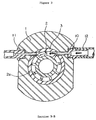
Figure 3: Sectional view of section B-B in Figure 2.
Figure 4: Sectional and side views of this embodiment using a flat coreless
electric motor.
Figure 5: Sectional view of an example in which the hollow motor is
supported by O-rings.
Figure 6: An example of conventional applications in which laser beams
enter an optical mixing plate which is parallel to the beams and no condenser lens is
used after said plate.
Figure 7: An example of applications in which a collimated laser beams
enters an optical mixing plate and the secondary light source image created by a
periodic structure in the plate is collimated into parallel light flux by means of a
condenser lens.
Figure 9: An application of the optical mixing plate of this invention in
which a tilted flat parallel plate is used in place of the optical mixing plate.
Figure 10: Another application of the optical mixing plate of this invention in
which a deflection prism is used in place of the optical mixing plate.
Best Embodiments of this Invention
The embodiments of this invention are described below. Figure 1 is the front
view of the first embodiment of this invention. Figure 2 is an enlarged sectional
view of section A-A in Figure 1. Figure 3 is the sectional view of section B-B in
Figure 2. An air motor is used to drive the hollow motor in this embodiment.
In these drawings, the parts are denoted as follows: 1 body, 2 rotating center
shaft with vanes, 3 intermediate tube, 4 angular bearing, 5 spring washer, 6 circular
glass retaining fixture, 7 stepped fixation ring, 8 optical mixing plate, 9 window
glass, 10 air jet port, 11 air discharge port, 12 tube, and 13 air compressor.
The body 1 has a cylindrical through-hole at the center as shown in Figure 2.
In this through-hole, the rotating center shaft equipped with vanes 2 is held in place
by angular bearings 4 and 4, circular glass retaining fixture 6, and stepped fixation
rings 7 and 7 so that the rotating center shaft can rotate freely. The inner rings of the
angular bearings 4 holding the rotating center shaft 2 in place are fixed directly or by
the stepped fixation ring 7 via spring washer 5. The side of the outer ring of the
angular bearing 4 is fixed by the circular glass retaining fixture 6. Spring washer 5 is
used on the right side only in Figure 2. It is possible to use this washer on the left
side or on both sides.
The rotating center shaft equipped with vanes 2 is provided with a through
hole 2b at the center to allow the laser beams to pass through it. Multiple vanes 2a
are formed on the periphery of the center shaft at equal distances as shown in Figure
3. The rotating center shaft 2 rotates when high pressure air strikes the vanes 2a.
Said vanes are located between angular bearings 4 and 4 as shown in Figure 2. The
intermediate tube 3 is placed around the vanes. High pressure air is jetted from air
jet port 10 (to be described later) at vanes 2a to rotate the rotating center shaft 2. The
body 1 is provided with an air jet port 10 and an air discharge port 11, which are
connected to each other to form a flow path. Said vanes 2a are located in said flow
path. The air jet port 10 is connected to an air compressor via tube 12.
The relationships of vanes 2a, intermediate tube 3, and angular bearings 4 are
not necessarily limited to those shown in the figures. Various other means may be
used provided that high pressure air strikes the vanes 2a on the rotating center shaft
2 to rotate it at high speed.
In Figure 2, stepped fixation ring 7 with a through hole at the center is
mounted on the laser beam exit side of the rotating center shaft equipped with vanes
2 via the spring washer 5. The optical mixing plate 8 is fitted into the through hole
of the stepped fixation ring 7 using an appropriate means (adhesive, screws, etc.) so
that the optical mixing plate 8 rotates at high speed together with the rotating center
shaft equipped with vanes 2.
A circular glass retaining fixture 6 is mounted on either end and outside of
the rotating center shaft equipped with vanes 2. A window glass 9 is fastened to each
of said circular glass retaining fixtures 6 using an appropriate means.
With the optical mixer constructed as above, laser beams enter the window
glass 9 on the left side as shown in Figure 2, pass through the hole 2b of the rotating
center shaft 2 and optical mixing plate 8, and exit from the window glass 9 on the
right side. Said optical mixing plate should preferably be located as close as possible
to the end face of the body on the laser beam exit side. The optical mixer should also
be constructed as thin as possible.
The optical mixer constructed as above is described below. A lemon skin
filter (diffuser) is used as the optical mixing plate.
A typical lemon skin filter is an assembly of convex lenses with random,
different and small focal distances. To reduce cost in practical applications, plate
glasses are frosted by rough grinding and chemically etched to reduce scattering.
This treatment gives the surface the appearance of lemon skin. The product is
therefore not an assembly of convex lenses with uniform small focal distances (a
micro-lens array) but a random, nonperiodic structure consisting of convex and
concave lenses of random focal distances.
The rotating center shaft equipped with vanes 2 of the hollow motor rotates
at high speed (e.g. at a peripheral speed of at least 1800 times per minute relative to
the laser beam diameter) when struck by high-pressure air from the air compressor
jetted from the air jet port 10. The laser beams enter the window glass 9 on the left
side as shown in Figure 2, pass through the hole 2b of the rotating center shaft with
vanes 2 and optical mixing plate 8, and exit from the window glass 9 on the right
side.
At that time, in Figure 2, the laser beams are scattered on the lemon skin
filter which retains the effects of its assembly of convex and concave lenses with
random, different and small focal distances. When the filter rotates, the scattered
laser beams are mixed and the length of the light path changes quickly. As a result,
the incident laser beams are virtually incoherent in terms of time average.
The center shaft of the hollow motor can rotate at a speed of more than
10,000 rpm. When a laser beam 1 mm in diameter is emitted to an area 3.2 mm in
radius around the center of the optical mixing plate, radiations of different states
(different wave trains) are emitted 200,000 times per minute. Incoherence of the
laser beam is virtually guaranteed, assuming time average, at frequencies lower than
at least 3.3 kHz.
Experiments have shown that, in this state, speckle patterns can be
completely removed from ordinary detectors. Incoherence of the laser beam is
virtually achieved, assuming time average, at frequencies lower than at least 30 kHz
if a larger size of hollow motor is used; the area is 10 mm in radius around the center
of the optical mixing plate; and the laser beam diameter is tightened to 0.3 mm.
Interference fringes are not recorded on ordinary video cameras if the optical mixing
plate rotates at or above the peripheral speed of 1800 times per minute (30 Hz in this
case) relative to the laser beam diameter. It is safe, however, to select a speed of at
least several times the above value.
The above optical mixing plate may be, in place of a lemon skin filter, a
frosted glass obtained immediately before optical polishing called a diffusion plate
or a beam-forming diffuser from Physical Optics Corporation. (This beam-forming
diffuser has a surface relief hologram and has the same effects as an array of micro-concave
lenses.) Other holographic plates available include a diffractive optical
element marketed by Edmund Optics Japan as a diffraction pattern generator
product. The coherence unique to the laser beam can also be made incoherent in
terms average, by the use of time of periodical structures such as fly's-eye lenses
and micro-lens arrays depending on the way such components are used.
The second embodiment of this invention is described below. This example
features a flat coreless electric motor as the hollow motor to rotate the optical
mixing plate. Figure 4 shows a sectional view and a side view of the second
embodiment of this invention using a flat coreless electric motor.
In the figure the parts are denoted as follows: 21 outer tube, 22 rotating
center shaft with yoke, 23 fixation ring with lid, 24 angular bearing, 25 coil support
plate, 26 coil, 27 yoke, 28 magnet, 29 optical mixing plate, 30 case, 31 spring
washer, 32 cable, 33 machine screw, and 34 pan head screw.
The outer rings of the two angular bearings 24 are press-fitted into outer tube
21 by double combination. The rotating center shaft with yoke 22 is fitted into the
inner rings of angular bearings 24 and fastened by the fixation ring with lid 23 via
spring washer 31. A through hole 22a passes through the center of the rotating
center shaft with yoke 22. The yoke 27 is fastened to the center shaft 22 by a pan
head screw 34. A magnet 28 is fastened to said yoke 27. The yoke 27 is provided
with a through hole 27a at the center, which connects to through hole 22a. The
optical mixing plate 29 is mounted on the outlet of through hole 27a and fixed by a
suitable means (adhesion, etc.). A case 30, fastened to the outer tube 21, is mounted
on the outside of the optical mixing plate 29. In the above structure, the rotating
center shaft with yoke 22 rotates together with the integrally mounted spring washer
31 and fixation ring with lid 23. It is also possible to use other support means
replacing spring washer 31 and fixation ring with lid 23 and to support only the
rotating center shaft with yoke 22 on the angular bearings and rotate it.
Coil support plate 25 is fastened to the outer tube 21 by machine screw 33.
Coil 26, set on the coil support plate 25, connects to a power supply (not shown) via
a cable. Coil 26, yoke 27, and magnet 28 comprise the conventionally known flat
coreless electric motor.
With the optical mixer of this invention constructed as above, when coil 26 is
energized, magnet 28 and yoke 27 rotate, and the optical mixing plate 29 also
rotates. It is possible, as in the first embodiment of this invention, to make the laser
beam passing through optical mixing plate 29 virtually incoherent. Since the
operating principle of the electric motor is identical to that of a conventionally
known flat coreless motor, a detailed explanation is omitted here.
The third embodiment of this invention is described below.
The third embodiment of this invention features an anti-vibration means.
Figure 5 shows a section of the embodiment of this invention in which the
hollow motor is supported by O-rings as cushions. The optical mixer is supported on
the housing via the O-rings placed along the periphery and on both the right and left
sides of said optical mixer. Vibration transferred to the housing is absorbed by the
O-rings. The rotor is symmetrically structured in terms of both mass and shape
which prevents vibrations of 100 Hz and below that are harmful for microscope and
measuring equipment. The remaining high harmonic vibrations can easily be
prevented by installing O-rings or other cushions in the housing.
Some specific structures of the optical mixer of this invention have been
introduced. The use the optical mixer of this invention is described below. The
drawings referred to in the description below show only the relationship between the
optical mixing plate and laser beams.
Figure 6 shows an example of typical applications in which laser beams enter
the optical mixing plate that is parallel to the beams and no condenser lens is used
after said plate.
Figure 7 shows an example of applications in which parallel laser beams
enter the optical mixing plate. The secondary light source image created by a
periodic structure is converted into a parallel light flux by means of a condenser
lens.
Figure 8 shows laser beams that are focused on the optical mixing plate and
then used as parallel light flux by lenses or other means. (This also applies to the
optical mixing plate that is installed in the reverse beam expander.)
Lemon skin filters and beam-forming diffusers can be used as random
nonperiodic structures in any of methods shown in Figures 6, 7 and 8.
The methods shown in Figures 7 and 8 are recommended for use when a
periodic structural holographic plate (diffraction pattern generator), fly-eye lens, and
micro-lens array are included.
Figure 9 is an example of applications of the optical mixing plate of this
invention in which a tilted flat parallel plate is used in place of the optical mixing
plate.
To create this condition, laser beams are aimed at the rotating center shaft
and refracted on the flat parallel plate, and an orbicular light is generated as the
hollow motor rotates. The radius of the annulus light depends on the angle of tilt and
the thickness of the flat parallel plate.
This annulus illumination introduces laser beams to the margins of the
objective lens of a microscope and generates fluorescence through total internal
reflection (at the interface between glass and solution) (excitation of evanescent
waves). Figure 10 shows another example of an application of the optical mixing
plate of this invention in which a wedge prism is used in place of the optical mixing
plate.
To create this condition, laser beams are incident at the rotating center shaft
and refracted on a wedge prism, and an orbicular light with an angle of inclination of
annulus light is generated as the hollow motor rotates. The angle of inclination of
annulus light depends on the vertical angle of the wedge prism.
As described above, the orbicular light can be mixed using the hollow motor.
It is also possible to design the unit compactly and make it symmetrical about the
rotating center shaft in terms of both shape and mass, which serves to reduce
vibrations significantly.
Implementation of the optical mixer with a hollow motor of this invention
has been described. Other means of driving the hollow motor may be used
including, for example, a gear drive. The optical mixing plate and the method of
using it are not limited to what is described above but various other utilization
methods can be adopted.
This invention may be implemented in various other forms of embodiment
without deviating from the spirit of its main features. The above-mentioned
embodiments are therefore only a few examples and should not be construed as
limiting.
Industrial Applicability
This invention enables the construction of a compact optical mixer. It is
therefore easy to incorporate it in optical equipment or install it as an external unit
on existing equipment. It is also easy to make the laser beam virtually incoherent at
frequencies lower than at least 3.3 kHz. In this state, speckle patterns, which cause
problems in a wide range of applications, are completely removed from ordinary
detectors. It is also easy to realize virtual incoherence at frequencies lower than 30
kHz assuming minor changes in the setting conditions.
It is possible to use laser beams extensively as bright light sources that
feature the exceedingly monochromatic output of the laser. The industrial merits and
applicable fields are infinite.
The motor load is low, and a super high-speed, low vibration optical mixer is
realized because the use of a hollow motor allows the use of a compact circular
optical mixing plate.
By using a hollow motor, not limited to an air motor or flat electric motor,
the compact optical mixing plate can be installed as close as possible to the end face
on the laser emitting side. In addition, a thin optical mixer has been designed.
Because of these structural features, the light spread from optical mixing plate, not
limited to laser beams, is collected effectively by lenses, making it possible to
enlarge and homogenize the light source image and otherwise expand the fields of
practical application.
Since this is a compact optical mixer with the drive motor designed
symmetrically in terms of both mass and shape to reduce vibrations, and with the
remaining high harmonic vibrations absorbed by O-rings and other cushions
installed in the housing, the optical mixer of this invention is easily built into optical
equipment or can be externally attached.
By incorporating a tilted flat parallel plate or a wedge prism in place of the
mixing plate, annulus illumination from parallel annulus light or annulus light with
an angle of inclination can be formed within a lighting system such as microscope or
exposure device, with the unnecessary interference fringes removed. These are some
of the excellent effects of this invention.