EP1514971B1 - Support pour un filtre dans une bouche d'égout - Google Patents
Support pour un filtre dans une bouche d'égout Download PDFInfo
- Publication number
- EP1514971B1 EP1514971B1 EP04021675A EP04021675A EP1514971B1 EP 1514971 B1 EP1514971 B1 EP 1514971B1 EP 04021675 A EP04021675 A EP 04021675A EP 04021675 A EP04021675 A EP 04021675A EP 1514971 B1 EP1514971 B1 EP 1514971B1
- Authority
- EP
- European Patent Office
- Prior art keywords
- holder
- gully
- filter
- outer part
- support means
- Prior art date
- Legal status (The legal status is an assumption and is not a legal conclusion. Google has not performed a legal analysis and makes no representation as to the accuracy of the status listed.)
- Expired - Lifetime
Links
- 238000007789 sealing Methods 0.000 claims abstract description 3
- 239000002352 surface water Substances 0.000 description 10
- 239000010802 sludge Substances 0.000 description 6
- XLYOFNOQVPJJNP-UHFFFAOYSA-N water Substances O XLYOFNOQVPJJNP-UHFFFAOYSA-N 0.000 description 4
- 238000001914 filtration Methods 0.000 description 2
- 238000009825 accumulation Methods 0.000 description 1
- 238000010276 construction Methods 0.000 description 1
- 230000003247 decreasing effect Effects 0.000 description 1
- 230000001419 dependent effect Effects 0.000 description 1
- 239000000463 material Substances 0.000 description 1
- 238000000746 purification Methods 0.000 description 1
- 239000004576 sand Substances 0.000 description 1
- 239000010935 stainless steel Substances 0.000 description 1
- 229910001220 stainless steel Inorganic materials 0.000 description 1
- 238000010025 steaming Methods 0.000 description 1
- 239000000126 substance Substances 0.000 description 1
- 238000011179 visual inspection Methods 0.000 description 1
Images

Classifications
-
- E—FIXED CONSTRUCTIONS
- E03—WATER SUPPLY; SEWERAGE
- E03F—SEWERS; CESSPOOLS
- E03F5/00—Sewerage structures
- E03F5/04—Gullies inlets, road sinks, floor drains with or without odour seals or sediment traps
- E03F5/0401—Gullies for use in roads or pavements
- E03F5/0404—Gullies for use in roads or pavements with a permanent or temporary filtering device; Filtering devices specially adapted therefor
-
- E—FIXED CONSTRUCTIONS
- E03—WATER SUPPLY; SEWERAGE
- E03F—SEWERS; CESSPOOLS
- E03F1/00—Methods, systems, or installations for draining-off sewage or storm water
-
- C—CHEMISTRY; METALLURGY
- C02—TREATMENT OF WATER, WASTE WATER, SEWAGE, OR SLUDGE
- C02F—TREATMENT OF WATER, WASTE WATER, SEWAGE, OR SLUDGE
- C02F1/00—Treatment of water, waste water, or sewage
- C02F1/001—Processes for the treatment of water whereby the filtration technique is of importance
-
- C—CHEMISTRY; METALLURGY
- C02—TREATMENT OF WATER, WASTE WATER, SEWAGE, OR SLUDGE
- C02F—TREATMENT OF WATER, WASTE WATER, SEWAGE, OR SLUDGE
- C02F2103/00—Nature of the water, waste water, sewage or sludge to be treated
- C02F2103/001—Runoff or storm water
-
- C—CHEMISTRY; METALLURGY
- C02—TREATMENT OF WATER, WASTE WATER, SEWAGE, OR SLUDGE
- C02F—TREATMENT OF WATER, WASTE WATER, SEWAGE, OR SLUDGE
- C02F2307/00—Location of water treatment or water treatment device
- C02F2307/08—Treatment of wastewater in the sewer, e.g. to reduce grease, odour
Definitions
- the present invention relates to a holder for gully filter.
- the filter holder comprises an outer part and an inner part, which is arranged inside the outer part.
- the inner part is arranged to hold a filter.
- Filtering of surface water is an important part of the way of the water through our society. Greater and greater demands are made on purification of the surface water before the water reaches the recipient, which may be a lake or a river. For surface water, it becomes increasingly common with filters directly in the surface-water gully. This is particularly important in surface-water gullies placed in exposed environments such as parking places and filling stations.
- CA-A-2296034 discloses a holder for a gully filter, which holder comprises a basket support installed in a sewer pipe.
- a basket with a filter screen rests on and within the basket support and has a handle for removal of the filled basket.
- the basket support includes a circular flat strip that is extendable to fit into the sewer pipe. The flat strip forces the basket support against the sewer wall so as to keep the basket support with sealing abutment against the entire wall.
- the object of the present invention is to provide an improved filter holder for use in a gully, which filter holder solves the above-mentioned problems.
- the filter holder in question enables that the filter is replaced in an easy and fast way.
- the construction of the filter holder enables visual inspection of the degree of clogging of the filter without the holder having to be lifted up from the gully, and that equipment for, among other things, sludge removal and supply of steam can be inserted into the gully with the filter holder mounted therein.
- An additional object of the present invention is to provide good connection between the filter holder and the wall of the gully.
- the advantage is obtained that the filter holder, because said support means being arranged between the holder and said opposite inner side of said gully's inner wall, can be formed to only abut sealingly against a part of the inner wall of a gully. This ensures that a spack is provided between the holder the and said opposite inner side of said gully's inner wall which allows to visually inspect the degree of clogging of the filter, and sludge removal can be carried out without the filter holder needing to be moved from the position thereof. In this way, the advantage is obtained that the number of lifts of the filter holder upon such occasions is considerably decreased.
- the passage that has been provided between the filter holder and the gully's opposite side of said gully's inner wall furthermore ensures that the amount of water that has flowed into the gully not entirely is received in the holder, which entails that the holder upon a possible filter replacement is considerably lighter to lift out of the gully than previously known filter holders.
- the filter holder can be arranged to only occupy a part, preferably 30-70 %, and preferably max 50 %, of the horizontal cross-sectional area of a gully,
- the same holder may, e.g., be manufactured from some plastic material or stainless steel.
- the support means is arranged to support the filter holder against the wall in a gully.
- said support means is telescopically formed and can be locked in the desired position by means of a screw.
- the advantage is that the length of the support means can be adapted according to the design of the gully, and said support means can thereby be arranged to provide a pressing force against the filter holder.
- the length of the support means can of course also be adapted to the design of the gully by it being cut off to a suitable length.
- the support means may comprise at least one spring element in order to provide said pressing force against the filter holder.
- the filter holder may comprise a wedge that provides said pressing force against the filter holder.
- said support means may be provided with wheels for facilitating mounting and dismounting of the filter holder in a gully.
- the filter holder comprises an additional turnable support means. This is particularly advantageous in some older gullies where joints between parts may be present in the depth of the gully. When the parts frequently are somewhat displaced in relation to each other, this means that the wall of the gully is displaced laterally at the joints.
- the filter holder By providing the filter holder with two vertically displaced support means, a stable location of the filter is obtained also in case the wall of the gully has irregularities.
- the outer part of the filter holder may comprise guides in order to be able to displaceably connect the inner part to the outer part, wherein the inner part easily can be mounted into the outer part and held in place therein.
- the upper part upon mounting into a gully can be arranged to constitute a fall protection member.
- a clamp unit may be arranged at the upper part of the filter holder in order to be able to adapt the size of the fall protection member to the size of the cross-sectional area of the gully.
- said inner part comprises a handle in order to facilitate taking out of the inner part from the outer part upon a filter replacement.
- Said inner part may comprise a first and a second half, which are arranged to be able to assume an open position and a closed position in relation to each other for enabling the filter replacement.
- a support leg is arranged between the lower part of the outer part and the bottom of the gully so that said outer part of the holder should not stand on the bottom of the gully.
- said support leg may be telescopically formed and the length thereof can be locked in desired posilion by means of a screw.
- the length of the support leg may of course also be adapted to the desired distance between holder and gully bottom by it being cut off to a suitable length.
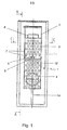
- FIG. 1-4 an embodiment of the present invention is shown, applied to a holder intended for filters in gullies.
- the filter holder 1 in the figures comprises an outer part 2, which detachably connects an inner part 3 by means of guides 7, the inner part 3 holding a filter 12 and comprises at least partly perforations 4 along the limiting surface thereof for enabling filtering of the water of a gully 17 between the inlet 15 and outlet 16 of the gully 17.
- a turnable support means 5 is attached at the outer part 2.
- the support means 5 Upon mounting into a gully 17, the support means 5 is folded out perpendicularly to the filter holder 1 and thereby supports the filter holder 1 against the inside of a gully17.
- the support means 5 is provided with a wheel 6, which assists upon mounting and dismounting of the filter holder 1 in the gully 17.
- a handle 8 is arranged at the inner part 3 to assist upon filter replacements when the inner part 3 should be lifted out from the outer part 2.
- the filter holder 1 comprises a clamp unit 9, intended to work as an extended fall protection member, arranged at the upper part of the filter holder 1.
- a clamp unit 9 intended to work as an extended fall protection member, arranged at the upper part of the filter holder 1.
- the upper part of the filter holder 1 is opened, in figure 2 shown as a gap 10 having hinges 11 in the lowered position thereof, and then the inner part 3 is lifted out from the outer part 2.
- the filter 12 inside the inner part 3 is then replaced and the inner part 3 is again pushed down into the outer part 2.
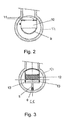
- FIG 3 a section view C-C of the holder 1 according to figure 1 is shown.
- the filter holder1 is shown straight from above and the inner part 3, comprising the filter 12, is here in a pushed-down position in the outer part 2.
- the support means 5 comprises two spring elements 13 arranged between the outer part 2 and said support means 5.
- the filter holder 1 occupies only a part of the cross-sectional area of a gully 17. Thereby, passage down into the gully 17 of, for instance, a sludge-removal hose or equipment for steaming away possible ice plugs is allowed.
- FIG 4 there is also shown how the support means 5 is turned out from the filter holder 1 and how the support means 5 in the folded-out position thereof assumes a perpendicular position to the filter holder 1. The folded-out position of the support means 5 is also illustrated in figure 1 .
- a support leg 14 is arranged at the lower part of the outer part 2 and the bottom of the gully17. A space is thereby formed between the lower part of the outer part 2 and the bottom of the gully 17, which means an extended space for accumulation of sludge and gravel. Said support leg 14 is also illustrated in figure 1 .
Landscapes
- Health & Medical Sciences (AREA)
- Life Sciences & Earth Sciences (AREA)
- Engineering & Computer Science (AREA)
- Hydrology & Water Resources (AREA)
- Public Health (AREA)
- Water Supply & Treatment (AREA)
- Sewage (AREA)
- Filtering Of Dispersed Particles In Gases (AREA)
- Piezo-Electric Or Mechanical Vibrators, Or Delay Or Filter Circuits (AREA)
- Lubrication Details And Ventilation Of Internal Combustion Engines (AREA)
- Filtration Of Liquid (AREA)
- Sink And Installation For Waste Water (AREA)
Claims (10)
- Support (1) pour un filtre dans une bouche d'égout, comprenant une partie extérieure (2) et une partie intérieure (3), la partie intérieure (3) étant reliée de manière détachable à la partie extérieure (2) et ladite partie intérieure (3) étant munie d'un filtre (12), caractérisé en ce qu'au moins un moyen d'appui (5) est agencé de manière à pouvoir tourner au niveau de la partie extérieure (2) du support (1), lequel moyen d'appui (5) dépasse hors de la partie extérieure (2) de façon à maintenir le support (1) en place en butée étanche contre une partie de la paroi intérieure d'une bouche d'égout(17).
- Support pour un filtre dans une bouche d'égout selon l'une quelconque des revendications précédentes, caractérisé en ce que l'un au moins desdits moyens d'appui (5) présente une forme télescopique et peut être bloqué dans la position voulue à l'aide d'une vis.
- Support pour un filtre dans une bouche d'égout selon l'une quelconque des revendications précédentes, caractérisé en ce que l'un au moins desdits moyens d'appui (5) est muni de roulettes (6).
- Support pour un filtre dans une bouche d'égout selon l'une quelconque des revendications précédentes, caractérisé en ce que l'un au moins desdits moyens d'appui (5) comprend au moins un élément à ressort (13) qui exerce une force de pression contre le support (1).
- Support pour un filtre dans une bouche d'égout selon l'une quelconque des revendications précédentes, caractérisé en ce que le support (1) comprend une cale en coin qui est agencée pour être placée entre l'un au moins desdits moyens d'appui (5) et le côté intérieur opposé de la paroi intérieure de ladite bouche d'égout (17) afin d'exercer ladite force de pression contre le support (1).
- Support pour un filtre dans une bouche d'égout selon l'une quelconque des revendications précédentes, caractérisé en ce qu'il comprend au moins deux moyens d'appui (5) qui sont agencés avec un écartement vertical l'un par rapport à l'autre.
- Support pour un filtre dans une bouche d'égout selon l'une quelconque des revendications précédentes, caractérisé en ce que la partie extérieure (2) comprend des guides (7) pour relier la partie intérieure (3) de manière déplaçable à la partie extérieure (2).
- Support pour un filtre dans une bouche d'égout selon l'une quelconque des revendications précédentes, caractérisé en ce que ladite partie intérieure (3) comprend une poignée (8) permettant de détacher complètement la partie intérieure (3) de la partie extérieure (2) sans qu'il soit nécessaire de sortir la partie extérieure (2) de la bouche d'égout(17).
- Support pour un filtre dans une bouche d'égout selon l'une quelconque des revendications précédentes, caractérisé en ce qu'un pied support (14) est agencé entre le dessous de la partie extérieure (2) et le fond de la bouche d'égout(17).
- Support pour un filtre dans une bouche d'égout selon la revendication 9, caractérisé en ce que ledit pied support (14) a une forme télescopique et peut être bloqué dans la position voulue à l'aide d'une vis.
Applications Claiming Priority (2)
| Application Number | Priority Date | Filing Date | Title |
|---|---|---|---|
| SE0302445 | 2003-09-11 | ||
| SE0302445A SE0302445D0 (sv) | 2003-09-11 | 2003-09-11 | Hållare för dagvattenfilter |
Publications (2)
| Publication Number | Publication Date |
|---|---|
| EP1514971A1 EP1514971A1 (fr) | 2005-03-16 |
| EP1514971B1 true EP1514971B1 (fr) | 2011-08-10 |
Family
ID=28787325
Family Applications (1)
| Application Number | Title | Priority Date | Filing Date |
|---|---|---|---|
| EP04021675A Expired - Lifetime EP1514971B1 (fr) | 2003-09-11 | 2004-09-13 | Support pour un filtre dans une bouche d'égout |
Country Status (5)
| Country | Link |
|---|---|
| EP (1) | EP1514971B1 (fr) |
| AT (1) | ATE519895T1 (fr) |
| DK (1) | DK1514971T3 (fr) |
| ES (1) | ES2371473T3 (fr) |
| SE (1) | SE0302445D0 (fr) |
Families Citing this family (1)
| Publication number | Priority date | Publication date | Assignee | Title |
|---|---|---|---|---|
| FR2916458B1 (fr) * | 2007-05-25 | 2009-08-07 | Constru Sa | Bouche d'egout avec un puits equipe d'un porte-filtre et d'un filtre amovible |
Family Cites Families (3)
| Publication number | Priority date | Publication date | Assignee | Title |
|---|---|---|---|---|
| WO1999042405A1 (fr) * | 1998-02-18 | 1999-08-26 | Abtech Industries, Inc. | Collecteurs d'eaux de ruissellement a bouche sous trottoir destines a filtrer les detritus et les hydrocarbures |
| CA2296034C (fr) * | 2000-01-17 | 2002-07-16 | Gilles Remon | Panier d'egout et support connexe |
| US6767456B2 (en) * | 2001-03-19 | 2004-07-27 | Circle Environmental, Inc. | Reusable storm water sampler and pollutant filter insert |
-
2003
- 2003-09-11 SE SE0302445A patent/SE0302445D0/xx unknown
-
2004
- 2004-09-13 DK DK04021675.6T patent/DK1514971T3/da active
- 2004-09-13 EP EP04021675A patent/EP1514971B1/fr not_active Expired - Lifetime
- 2004-09-13 AT AT04021675T patent/ATE519895T1/de not_active IP Right Cessation
- 2004-09-13 ES ES04021675T patent/ES2371473T3/es not_active Expired - Lifetime
Also Published As
| Publication number | Publication date |
|---|---|
| ATE519895T1 (de) | 2011-08-15 |
| ES2371473T3 (es) | 2012-01-03 |
| SE0302445D0 (sv) | 2003-09-11 |
| DK1514971T3 (da) | 2012-01-09 |
| EP1514971A1 (fr) | 2005-03-16 |
Similar Documents
| Publication | Publication Date | Title |
|---|---|---|
| US6562233B1 (en) | Storm drain line with riser 2 | |
| US6884343B2 (en) | Curb inlet catch basin filter | |
| US5405539A (en) | Storm drain filter system | |
| US7201843B2 (en) | Framed storm drain insert sediment filter | |
| US20050109693A1 (en) | Downspout filter | |
| US20050199537A1 (en) | Storm drain filtration system | |
| CN103382739B (zh) | 一种雨水口截污装置及其使用方法 | |
| US20060049085A1 (en) | Quick release drain filter apparatus and system | |
| CN202113672U (zh) | 反冲洗精密过滤器 | |
| EP1514971B1 (fr) | Support pour un filtre dans une bouche d'égout | |
| CN212534420U (zh) | 一种市政工程用多层过滤雨水口装置 | |
| CN109647026B (zh) | 用于排水管路的过滤装置及其安装方法 | |
| CN210086430U (zh) | 一种防堵型市政雨水管道 | |
| WO2006079141A1 (fr) | Appareil de purification d'eau | |
| CN218725649U (zh) | 环境水取样装置 | |
| CN111622325B (zh) | 一种市政排水系统 | |
| CN105714918B (zh) | 一种雨水口垃圾过滤循环系统的过滤装置 | |
| CN210917666U (zh) | 一种市政下水管道排水结构 | |
| CN210214868U (zh) | 一种多级过滤式分离设备 | |
| JP4636386B2 (ja) | 管内濁質除去装置並びにその吸込ノズルの設置方法 | |
| KR100627572B1 (ko) | 하수 맨홀 쓰레기 제거 장치 | |
| CN212224133U (zh) | 带有过滤装置的地下污水管道 | |
| CN219753436U (zh) | 一种地下管网清淤装置 | |
| CN218441271U (zh) | 一种水利管道 | |
| CN115853095B (zh) | 具有过滤装置的市政用排水管道 |
Legal Events
| Date | Code | Title | Description |
|---|---|---|---|
| PUAI | Public reference made under article 153(3) epc to a published international application that has entered the european phase |
Free format text: ORIGINAL CODE: 0009012 |
|
| AK | Designated contracting states |
Kind code of ref document: A1 Designated state(s): AT BE BG CH CY CZ DE DK EE ES FI FR GB GR HU IE IT LI LU MC NL PL PT RO SE SI SK TR |
|
| AX | Request for extension of the european patent |
Extension state: AL HR LT LV MK |
|
| 17P | Request for examination filed |
Effective date: 20050916 |
|
| AKX | Designation fees paid |
Designated state(s): AT BE BG CH CY CZ DE DK EE ES FI FR GB GR HU IE IT LI LU MC NL PL PT RO SE SI SK TR |
|
| RAP1 | Party data changed (applicant data changed or rights of an application transferred) |
Owner name: FLEXICLEAN AB |
|
| RIN1 | Information on inventor provided before grant (corrected) |
Inventor name: ENEROTH, LEIF |
|
| GRAP | Despatch of communication of intention to grant a patent |
Free format text: ORIGINAL CODE: EPIDOSNIGR1 |
|
| GRAS | Grant fee paid |
Free format text: ORIGINAL CODE: EPIDOSNIGR3 |
|
| GRAA | (expected) grant |
Free format text: ORIGINAL CODE: 0009210 |
|
| AK | Designated contracting states |
Kind code of ref document: B1 Designated state(s): AT BE BG CH CY CZ DE DK EE ES FI FR GB GR HU IE IT LI LU MC NL PL PT RO SE SI SK TR |
|
| REG | Reference to a national code |
Ref country code: GB Ref legal event code: FG4D |
|
| REG | Reference to a national code |
Ref country code: CH Ref legal event code: EP |
|
| REG | Reference to a national code |
Ref country code: IE Ref legal event code: FG4D |
|
| REG | Reference to a national code |
Ref country code: SE Ref legal event code: TRGR |
|
| REG | Reference to a national code |
Ref country code: DE Ref legal event code: R096 Ref document number: 602004033825 Country of ref document: DE Effective date: 20111103 |
|
| REG | Reference to a national code |
Ref country code: NL Ref legal event code: VDEP Effective date: 20110810 |
|
| REG | Reference to a national code |
Ref country code: ES Ref legal event code: FG2A Ref document number: 2371473 Country of ref document: ES Kind code of ref document: T3 Effective date: 20120103 |
|
| REG | Reference to a national code |
Ref country code: DK Ref legal event code: T3 |
|
| PG25 | Lapsed in a contracting state [announced via postgrant information from national office to epo] |
Ref country code: NL Free format text: LAPSE BECAUSE OF FAILURE TO SUBMIT A TRANSLATION OF THE DESCRIPTION OR TO PAY THE FEE WITHIN THE PRESCRIBED TIME-LIMIT Effective date: 20110810 Ref country code: PT Free format text: LAPSE BECAUSE OF FAILURE TO SUBMIT A TRANSLATION OF THE DESCRIPTION OR TO PAY THE FEE WITHIN THE PRESCRIBED TIME-LIMIT Effective date: 20111212 |
|
| REG | Reference to a national code |
Ref country code: AT Ref legal event code: MK05 Ref document number: 519895 Country of ref document: AT Kind code of ref document: T Effective date: 20110810 |
|
| PG25 | Lapsed in a contracting state [announced via postgrant information from national office to epo] |
Ref country code: AT Free format text: LAPSE BECAUSE OF FAILURE TO SUBMIT A TRANSLATION OF THE DESCRIPTION OR TO PAY THE FEE WITHIN THE PRESCRIBED TIME-LIMIT Effective date: 20110810 Ref country code: CY Free format text: LAPSE BECAUSE OF FAILURE TO SUBMIT A TRANSLATION OF THE DESCRIPTION OR TO PAY THE FEE WITHIN THE PRESCRIBED TIME-LIMIT Effective date: 20110810 Ref country code: GR Free format text: LAPSE BECAUSE OF FAILURE TO SUBMIT A TRANSLATION OF THE DESCRIPTION OR TO PAY THE FEE WITHIN THE PRESCRIBED TIME-LIMIT Effective date: 20111111 Ref country code: PL Free format text: LAPSE BECAUSE OF FAILURE TO SUBMIT A TRANSLATION OF THE DESCRIPTION OR TO PAY THE FEE WITHIN THE PRESCRIBED TIME-LIMIT Effective date: 20110810 Ref country code: SI Free format text: LAPSE BECAUSE OF FAILURE TO SUBMIT A TRANSLATION OF THE DESCRIPTION OR TO PAY THE FEE WITHIN THE PRESCRIBED TIME-LIMIT Effective date: 20110810 |
|
| PG25 | Lapsed in a contracting state [announced via postgrant information from national office to epo] |
Ref country code: BE Free format text: LAPSE BECAUSE OF FAILURE TO SUBMIT A TRANSLATION OF THE DESCRIPTION OR TO PAY THE FEE WITHIN THE PRESCRIBED TIME-LIMIT Effective date: 20110810 |
|
| PG25 | Lapsed in a contracting state [announced via postgrant information from national office to epo] |
Ref country code: MC Free format text: LAPSE BECAUSE OF NON-PAYMENT OF DUE FEES Effective date: 20110930 Ref country code: SK Free format text: LAPSE BECAUSE OF FAILURE TO SUBMIT A TRANSLATION OF THE DESCRIPTION OR TO PAY THE FEE WITHIN THE PRESCRIBED TIME-LIMIT Effective date: 20110810 Ref country code: CZ Free format text: LAPSE BECAUSE OF FAILURE TO SUBMIT A TRANSLATION OF THE DESCRIPTION OR TO PAY THE FEE WITHIN THE PRESCRIBED TIME-LIMIT Effective date: 20110810 |
|
| REG | Reference to a national code |
Ref country code: CH Ref legal event code: PL |
|
| PG25 | Lapsed in a contracting state [announced via postgrant information from national office to epo] |
Ref country code: EE Free format text: LAPSE BECAUSE OF FAILURE TO SUBMIT A TRANSLATION OF THE DESCRIPTION OR TO PAY THE FEE WITHIN THE PRESCRIBED TIME-LIMIT Effective date: 20110810 Ref country code: RO Free format text: LAPSE BECAUSE OF FAILURE TO SUBMIT A TRANSLATION OF THE DESCRIPTION OR TO PAY THE FEE WITHIN THE PRESCRIBED TIME-LIMIT Effective date: 20110810 Ref country code: IT Free format text: LAPSE BECAUSE OF FAILURE TO SUBMIT A TRANSLATION OF THE DESCRIPTION OR TO PAY THE FEE WITHIN THE PRESCRIBED TIME-LIMIT Effective date: 20110810 |
|
| PLBE | No opposition filed within time limit |
Free format text: ORIGINAL CODE: 0009261 |
|
| STAA | Information on the status of an ep patent application or granted ep patent |
Free format text: STATUS: NO OPPOSITION FILED WITHIN TIME LIMIT |
|
| REG | Reference to a national code |
Ref country code: IE Ref legal event code: MM4A |
|
| 26N | No opposition filed |
Effective date: 20120511 |
|
| PG25 | Lapsed in a contracting state [announced via postgrant information from national office to epo] |
Ref country code: CH Free format text: LAPSE BECAUSE OF NON-PAYMENT OF DUE FEES Effective date: 20110930 Ref country code: LI Free format text: LAPSE BECAUSE OF NON-PAYMENT OF DUE FEES Effective date: 20110930 Ref country code: IE Free format text: LAPSE BECAUSE OF NON-PAYMENT OF DUE FEES Effective date: 20110913 |
|
| REG | Reference to a national code |
Ref country code: DE Ref legal event code: R097 Ref document number: 602004033825 Country of ref document: DE Effective date: 20120511 |
|
| PG25 | Lapsed in a contracting state [announced via postgrant information from national office to epo] |
Ref country code: LU Free format text: LAPSE BECAUSE OF NON-PAYMENT OF DUE FEES Effective date: 20110913 |
|
| PG25 | Lapsed in a contracting state [announced via postgrant information from national office to epo] |
Ref country code: BG Free format text: LAPSE BECAUSE OF FAILURE TO SUBMIT A TRANSLATION OF THE DESCRIPTION OR TO PAY THE FEE WITHIN THE PRESCRIBED TIME-LIMIT Effective date: 20111110 |
|
| PG25 | Lapsed in a contracting state [announced via postgrant information from national office to epo] |
Ref country code: TR Free format text: LAPSE BECAUSE OF FAILURE TO SUBMIT A TRANSLATION OF THE DESCRIPTION OR TO PAY THE FEE WITHIN THE PRESCRIBED TIME-LIMIT Effective date: 20110810 |
|
| PG25 | Lapsed in a contracting state [announced via postgrant information from national office to epo] |
Ref country code: HU Free format text: LAPSE BECAUSE OF FAILURE TO SUBMIT A TRANSLATION OF THE DESCRIPTION OR TO PAY THE FEE WITHIN THE PRESCRIBED TIME-LIMIT Effective date: 20110810 |
|
| REG | Reference to a national code |
Ref country code: FR Ref legal event code: PLFP Year of fee payment: 12 |
|
| PGFP | Annual fee paid to national office [announced via postgrant information from national office to epo] |
Ref country code: GB Payment date: 20150928 Year of fee payment: 12 |
|
| REG | Reference to a national code |
Ref country code: FR Ref legal event code: PLFP Year of fee payment: 13 |
|
| GBPC | Gb: european patent ceased through non-payment of renewal fee |
Effective date: 20160913 |
|
| PG25 | Lapsed in a contracting state [announced via postgrant information from national office to epo] |
Ref country code: GB Free format text: LAPSE BECAUSE OF NON-PAYMENT OF DUE FEES Effective date: 20160913 |
|
| REG | Reference to a national code |
Ref country code: FR Ref legal event code: PLFP Year of fee payment: 14 |
|
| REG | Reference to a national code |
Ref country code: FR Ref legal event code: PLFP Year of fee payment: 15 |
|
| PGFP | Annual fee paid to national office [announced via postgrant information from national office to epo] |
Ref country code: FI Payment date: 20230921 Year of fee payment: 20 |
|
| PGFP | Annual fee paid to national office [announced via postgrant information from national office to epo] |
Ref country code: SE Payment date: 20230919 Year of fee payment: 20 Ref country code: FR Payment date: 20230915 Year of fee payment: 20 Ref country code: DK Payment date: 20230918 Year of fee payment: 20 Ref country code: DE Payment date: 20230921 Year of fee payment: 20 |
|
| PGFP | Annual fee paid to national office [announced via postgrant information from national office to epo] |
Ref country code: ES Payment date: 20231005 Year of fee payment: 20 |
|
| REG | Reference to a national code |
Ref country code: DE Ref legal event code: R071 Ref document number: 602004033825 Country of ref document: DE |
|
| REG | Reference to a national code |
Ref country code: DK Ref legal event code: EUP Expiry date: 20240913 |
|
| REG | Reference to a national code |
Ref country code: ES Ref legal event code: FD2A Effective date: 20240927 |
|
| PG25 | Lapsed in a contracting state [announced via postgrant information from national office to epo] |
Ref country code: ES Free format text: LAPSE BECAUSE OF EXPIRATION OF PROTECTION Effective date: 20240914 |
|
| REG | Reference to a national code |
Ref country code: SE Ref legal event code: EUG |
|
| PG25 | Lapsed in a contracting state [announced via postgrant information from national office to epo] |
Ref country code: ES Free format text: LAPSE BECAUSE OF EXPIRATION OF PROTECTION Effective date: 20240914 |