EP1514822A2 - Sheet reverse device - Google Patents
Sheet reverse device Download PDFInfo
- Publication number
- EP1514822A2 EP1514822A2 EP04020148A EP04020148A EP1514822A2 EP 1514822 A2 EP1514822 A2 EP 1514822A2 EP 04020148 A EP04020148 A EP 04020148A EP 04020148 A EP04020148 A EP 04020148A EP 1514822 A2 EP1514822 A2 EP 1514822A2
- Authority
- EP
- European Patent Office
- Prior art keywords
- sheet
- conveying
- reverse
- normal
- roller
- Prior art date
- Legal status (The legal status is an assumption and is not a legal conclusion. Google has not performed a legal analysis and makes no representation as to the accuracy of the status listed.)
- Withdrawn
Links
Images


Classifications
-
- B—PERFORMING OPERATIONS; TRANSPORTING
- B65—CONVEYING; PACKING; STORING; HANDLING THIN OR FILAMENTARY MATERIAL
- B65H—HANDLING THIN OR FILAMENTARY MATERIAL, e.g. SHEETS, WEBS, CABLES
- B65H7/00—Controlling article feeding, separating, pile-advancing, or associated apparatus, to take account of incorrect feeding, absence of articles, or presence of faulty articles
- B65H7/02—Controlling article feeding, separating, pile-advancing, or associated apparatus, to take account of incorrect feeding, absence of articles, or presence of faulty articles by feelers or detectors
- B65H7/06—Controlling article feeding, separating, pile-advancing, or associated apparatus, to take account of incorrect feeding, absence of articles, or presence of faulty articles by feelers or detectors responsive to presence of faulty articles or incorrect separation or feed
-
- B—PERFORMING OPERATIONS; TRANSPORTING
- B07—SEPARATING SOLIDS FROM SOLIDS; SORTING
- B07C—POSTAL SORTING; SORTING INDIVIDUAL ARTICLES, OR BULK MATERIAL FIT TO BE SORTED PIECE-MEAL, e.g. BY PICKING
- B07C3/00—Sorting according to destination
- B07C3/02—Apparatus characterised by the means used for distribution
- B07C3/08—Apparatus characterised by the means used for distribution using arrangements of conveyors
-
- B—PERFORMING OPERATIONS; TRANSPORTING
- B65—CONVEYING; PACKING; STORING; HANDLING THIN OR FILAMENTARY MATERIAL
- B65H—HANDLING THIN OR FILAMENTARY MATERIAL, e.g. SHEETS, WEBS, CABLES
- B65H15/00—Overturning articles
- B65H15/004—Overturning articles employing rollers
-
- B—PERFORMING OPERATIONS; TRANSPORTING
- B65—CONVEYING; PACKING; STORING; HANDLING THIN OR FILAMENTARY MATERIAL
- B65H—HANDLING THIN OR FILAMENTARY MATERIAL, e.g. SHEETS, WEBS, CABLES
- B65H29/00—Delivering or advancing articles from machines; Advancing articles to or into piles
- B65H29/58—Article switches or diverters
-
- B—PERFORMING OPERATIONS; TRANSPORTING
- B65—CONVEYING; PACKING; STORING; HANDLING THIN OR FILAMENTARY MATERIAL
- B65H—HANDLING THIN OR FILAMENTARY MATERIAL, e.g. SHEETS, WEBS, CABLES
- B65H2301/00—Handling processes for sheets or webs
- B65H2301/30—Orientation, displacement, position of the handled material
- B65H2301/33—Modifying, selecting, changing orientation
- B65H2301/333—Inverting
- B65H2301/3331—Involving forward reverse transporting means
- B65H2301/33312—Involving forward reverse transporting means forward reverse rollers pairs
-
- B—PERFORMING OPERATIONS; TRANSPORTING
- B65—CONVEYING; PACKING; STORING; HANDLING THIN OR FILAMENTARY MATERIAL
- B65H—HANDLING THIN OR FILAMENTARY MATERIAL, e.g. SHEETS, WEBS, CABLES
- B65H2301/00—Handling processes for sheets or webs
- B65H2301/30—Orientation, displacement, position of the handled material
- B65H2301/35—Spacing
-
- B—PERFORMING OPERATIONS; TRANSPORTING
- B65—CONVEYING; PACKING; STORING; HANDLING THIN OR FILAMENTARY MATERIAL
- B65H—HANDLING THIN OR FILAMENTARY MATERIAL, e.g. SHEETS, WEBS, CABLES
- B65H2301/00—Handling processes for sheets or webs
- B65H2301/40—Type of handling process
- B65H2301/44—Moving, forwarding, guiding material
- B65H2301/445—Moving, forwarding, guiding material stream of articles separated from each other
- B65H2301/4452—Regulating space between separated articles
-
- B—PERFORMING OPERATIONS; TRANSPORTING
- B65—CONVEYING; PACKING; STORING; HANDLING THIN OR FILAMENTARY MATERIAL
- B65H—HANDLING THIN OR FILAMENTARY MATERIAL, e.g. SHEETS, WEBS, CABLES
- B65H2511/00—Dimensions; Position; Numbers; Identification; Occurrences
- B65H2511/10—Size; Dimensions
- B65H2511/11—Length
-
- B—PERFORMING OPERATIONS; TRANSPORTING
- B65—CONVEYING; PACKING; STORING; HANDLING THIN OR FILAMENTARY MATERIAL
- B65H—HANDLING THIN OR FILAMENTARY MATERIAL, e.g. SHEETS, WEBS, CABLES
- B65H2511/00—Dimensions; Position; Numbers; Identification; Occurrences
- B65H2511/20—Location in space
- B65H2511/22—Distance
-
- B—PERFORMING OPERATIONS; TRANSPORTING
- B65—CONVEYING; PACKING; STORING; HANDLING THIN OR FILAMENTARY MATERIAL
- B65H—HANDLING THIN OR FILAMENTARY MATERIAL, e.g. SHEETS, WEBS, CABLES
- B65H2511/00—Dimensions; Position; Numbers; Identification; Occurrences
- B65H2511/50—Occurence
- B65H2511/51—Presence
- B65H2511/514—Particular portion of element
-
- B—PERFORMING OPERATIONS; TRANSPORTING
- B65—CONVEYING; PACKING; STORING; HANDLING THIN OR FILAMENTARY MATERIAL
- B65H—HANDLING THIN OR FILAMENTARY MATERIAL, e.g. SHEETS, WEBS, CABLES
- B65H2513/00—Dynamic entities; Timing aspects
- B65H2513/10—Speed
- B65H2513/11—Speed angular
-
- B—PERFORMING OPERATIONS; TRANSPORTING
- B65—CONVEYING; PACKING; STORING; HANDLING THIN OR FILAMENTARY MATERIAL
- B65H—HANDLING THIN OR FILAMENTARY MATERIAL, e.g. SHEETS, WEBS, CABLES
- B65H2513/00—Dynamic entities; Timing aspects
- B65H2513/20—Acceleration or deceleration
-
- B—PERFORMING OPERATIONS; TRANSPORTING
- B65—CONVEYING; PACKING; STORING; HANDLING THIN OR FILAMENTARY MATERIAL
- B65H—HANDLING THIN OR FILAMENTARY MATERIAL, e.g. SHEETS, WEBS, CABLES
- B65H2701/00—Handled material; Storage means
- B65H2701/10—Handled articles or webs
- B65H2701/13—Parts concerned of the handled material
- B65H2701/131—Edges
- B65H2701/1311—Edges leading edge
-
- B—PERFORMING OPERATIONS; TRANSPORTING
- B65—CONVEYING; PACKING; STORING; HANDLING THIN OR FILAMENTARY MATERIAL
- B65H—HANDLING THIN OR FILAMENTARY MATERIAL, e.g. SHEETS, WEBS, CABLES
- B65H2701/00—Handled material; Storage means
- B65H2701/10—Handled articles or webs
- B65H2701/13—Parts concerned of the handled material
- B65H2701/131—Edges
- B65H2701/1313—Edges trailing edge
-
- B—PERFORMING OPERATIONS; TRANSPORTING
- B65—CONVEYING; PACKING; STORING; HANDLING THIN OR FILAMENTARY MATERIAL
- B65H—HANDLING THIN OR FILAMENTARY MATERIAL, e.g. SHEETS, WEBS, CABLES
- B65H2701/00—Handled material; Storage means
- B65H2701/10—Handled articles or webs
- B65H2701/19—Specific article or web
- B65H2701/1912—Banknotes, bills and cheques or the like
Definitions
- the present invention relates to a sheet reverse device for reversing the conveying direction of sheets, for example, mails being conveyed.
- a mail processing apparatus to process mails such as, for example, sealed letters, post cards, etc. and a banknote processing apparatus to process banknotes are known.
- a mail processing apparatus is composed of a sheet take-out unit to take out sheets such as sealed letters, post cards, etc.
- a sheet conveying unit to convey taken out sheets between various units on a conveying path
- a discrimination unit to read image data from the front and back surfaces of sheets conveyed and discriminate a position where a stamp is pasted
- a twist reverse unit to reverse the front and back surfaces of a sheet by turning it by 180° centering on the conveying direction with a twist reverse belt
- a reverse controller to reverse the front and rear ends in the sheet conveying direction and the front and back of sheet at the same time
- a stamping unit to stamp a postmark on a pasted stamp
- a stacker to stack sheets in a stacking storage
- gates to sort sheets to respective units selectively.
- a twist reverse unit and a reverse controller are selectively used to move the position of a stamp pasted on a sheet to a position where a postmark can be stamped.
- a twist reverse unit turns (twist reversing) a sheet by 180° centering on the direction same as the sheet conveying direction.
- the reverse controller reverses the front and rear ends of a sheet in the conveying direction and the front and back of a sheet at the same time (the switchback reversing).
- an apparatus provided with a normal/reverse rotation roller, a hit blade, etc. to convey a sheet that is conveyed directly in the straight direction or in the reverse direction is devised as a sheet reverse controller.
- a conveying unit and other units are so controlled as to maintain a space (gap) between conveying sheets or a distance (pitch) between front edges of sheets being conveyed.
- a reverse controller when sheets are reversed, control to accelerate or decelerate a conveying speed of sheets is complicated. Therefore, before and after the reversing operation, a gap or pitch between sheets tend to change. In particular, when a gap or pitch after the reversing operation becomes short, sheets come too close each other in the conveying unit at the downstream side and sheets tends to jam easily.
- the sheet reverse device is also named reverse controller.
- FIG. 1 is a block diagram showing the control system of a sheet processing apparatus 1 of the present invention.
- a main controller 2 is composed of a CPU to process data sent from component units of sheet processing apparatus 1 and directs operations to the component units, a memory to store an application program required for the operation of this CPU, and controls the entire operation of the apparatus. Further, main controller 2 receives and processes data sent from a discrimination unit 15, a reject stacker 17, a seal unit 20, a stacker 21, etc. which will be described later and operates the component units.
- a take-out controller 3 is connected to main controller 2 and receives/transmits various data, and is composed of memories storing drivers to operate a take-out portion 13 that will be described later.
- a conveying controller 4 is connected to main controller 2, receives/transmits various data and is composed of a memory storing drivers to operate a twist reverse unit 18, a reverse controller (sheet reverse device) 19 and a conveying unit 14.
- shift sensor controller 5 As shift sensor controller 5 is connected to main controller 2, receives/transmits various data, receives detected data of sheet 12 from shift sensors 35 and 53 installed in reverse controller 19 and conveying unit 14 that will be described later and transmits this detected data to main controller 1.
- Gate controller 6 is connected to main controller 2, receives and transmits various data and controls the operations of gates 15a, 15b and 15c.
- FIG. 2 is a block diagram showing the construction of sheet processing apparatus 1 involved in the embodiments of the present invention.
- Sheet processing apparatus 1 shown in FIG. 2 discriminates stamps put on sheets 12 such as sealed letters, post cards, etc. and puts a postmark on the stamps.
- stamps put on sheets 12 such as sealed letters, post cards, etc.
- Such mails as sealed letters and postcards have sizes and stiffness largely differing from banknotes and valuable securities such as checks and are hard to treat.
- the apparatus is explained as a mail processing apparatus, it can be sufficiently used as a valuable security processing apparatus to treat valuable securities.
- Sheet processing apparatus 1 shown in FIG. 2 retains sealed letters, postcards and other mails (herein after called as sheet 12) together and is composed of take-out portion 13 to take out a sheet in the apparatus one by one, conveying unit 14 to convey a sheet to each unit along a conveying path such as a belt, rollers, etc., discrimination unit 15 to read image data on the front and back sides of conveyed sheet 12 and discriminate a stamp position put on a sheet 12, and a reject stacker 17 to stack sheets 12 with no stamp pasted and sheets that are pre-set to be rejected based on the result of discrimination of discrimination unit 15.
- conveying unit 14 to convey a sheet to each unit along a conveying path such as a belt, rollers, etc.
- discrimination unit 15 to read image data on the front and back sides of conveyed sheet 12 and discriminate a stamp position put on a sheet 12 and discriminate a stamp position put on a sheet 12, and a reject stacker 17 to stack sheets 12 with no stamp pasted and sheets that are pre
- Sheet processing apparatus 1 is further composed of twist reverse unit 18 to rotate (twist reverse) a sheet by 180° centering the same direction as the sheet conveying direction by the twist reverse belt, reverse controller (sheet reverse device) 19 to reverse (switchback reverse) the front and rear ends of sheet 12 in the conveying direction and the front and back sides of sheet 12 at the same time, seal unit 20 to put a postmark on a stamp pasted on sheet 12, stacker 21 to stack sheet 12 of which stamping process is completed in the stacking portion in order, and a gate 25a to sort sheets to the normal conveying path or reject stacker 17.
- Sheet processing apparatus 1 is further composed of a gate 25b to sort sheets to either the normal conveying path or twisted reverse unit 18 and a gate 25c to sort sheets to either the normal conveying path or reverse controller 19.
- Plural sheets 12 are stacked in take-out portion 13 in the random direction by operator who operates sheet processing apparatus 1. Plural sheets 12 stacked in take-out portion are separated one by one and taken out on conveying unit 14 and conveyed to discrimination unit 15. Discrimination unit 15 reads image data on the front and back sides of sheet 12, discriminates the position of a stamp put on sheet 12 and sends the discrimination result to main controller 1. Main controller 2 judges whether sheet 12 is an object for rejection based on the result of discrimination from discrimination unit 15. When sheet 12 is an object for rejection, gate 25a operates to send it to reject stacker 17. Further, when sheet 12 is judged to be other than an object for rejection, main controller 2 judges the necessity for twist reverse or switchback reverse from the position of a stamp put on sheet 12 and selects gate 25b or gate 25c and actuates it.
- a stamp pasted on sheet 12 being conveyed comes to a specified position, for example, the downstream side in the conveying direction and upside on the right side surface to the downstream in the conveying direction.
- This specified position is a place where a postmark can be stamped by seal unit 20 and is a position over which a stamp on sheet 12 passes.
- Sheet 12 stamped in seal unit 20 is conveyed to stacker 21 and stacked in the stacking portion sequentially.
- FIG. 3 shows a basic construction diagram of reverse controller 19 in the embodiments of the present invention.
- Reverse controller 19 is basically composed of a conveyor in a main body 27 and a reverse unit 29.
- the conveyor in main body 27 is composed of conveying rollers 31 and conveying belts 33 likewise conveying unit 14 and conveys sheet 12 by holding it with conveying belts 33.
- the conveyor in main body 27 is provided with shift sensors 35 and detects sheet 12. The reverse operation of reverse unit 29 is triggered by this detection. Shift sensors 35 detect a length of sheet 12 by detecting its front and rear ends.
- Reverse unit 29 is composed of a normal/reverse rotation roller 37 - equipped with a driving source independent from conveying rollers 31, etc., a pinch roller 39 that is driven following normal/reverse rotation roller 37, and guides 41 and 41 to lead sheet 12.
- Pinch roller 39 is attached rotatably to one end of an L-shaped lever 44.
- L-shaped lever 44 is supported in the oscillating state via a rotation fulcrum 43.
- the other end of L-shaped lever 44 is kept pilled by the restoring force of a spring 45 and pinch roller 39 is pressed against normal/reverse roller 37 by the oscillation of L-shaped lever 44 in the counterclockwise direction.
- a hit lever 47 which is driven by a solenoid and oscillates.
- lever 47 When lever 47 is oscillated, the front end of reversed sheet 12 is led to an exit side 19b of reverse controller 19.
- FIG. 4 is a graph showing the control of the operation of normal/reverse rotation roller 37 in the basic construction of reverse controller 19 shown in the first through the third embodiments and FIG. 3 of the present invention.
- the axis of abscissa of the graph shown in FIG. 4 indicates a time T (s), the axis of ordinate indicates a peripheral velocity (conveying velocity) V (m/s) of normal/reverse rotation roller 37.
- Peripheral velocity V0 of normal/reverse rotation roller 37 is almost the same velocity of the conveying velocity of conveying unit 14.
- the peripheral velocities V0, V1 are changes as appropriate according to characteristic amounts such as size, stiffness, weight of sheets 12 that are conveyed and not specifically restricted.
- pinch roller 39 rotates centering around pinch roller rotation fulcrum 43 according to a thickness of sheet 12 and escapes by the thickness of sheet 12.
- normal/reverse rotation roller 37 starts to rotate in the reverse direction (the counterclockwise direction in FIG. 3) and the peripheral velocity reaches -V0.
- normal/reverse rotation roller 37 performs a series of operations; that is, normal rotation at a constant velocity, acceleration, normal rotation at a constant velocity, deceleration, stop, acceleration in reverse rotation and reverse rotation at a constant velocity.
- a space that is, a gap (or pitch) between sheets 12 is maintained and therefore, it is possible to make a gap (or pitch) and improve the processing capacity of sheet processing apparatus 1.
- a gap is a distance to the front end of another sheet 12 being conveyed at the upstream side in the conveying direction rather than this sheet 12.
- a pitch is a distance from the front end of sheet 12 being conveyed to the front end of another sheet 12 being conveyed at the upstream side in the conveying direction rather than this sheet 12.
- the accelerating operation of normal/reverse rotation roller 37 is made at a different acceleration curve (accelerating inclination) based on the detection result of length of sheets 12 by shift sensors 35.
- sheets 12 that are conveyed are in the same size such as tickets or checks or when a difference in length is small as in banknotes, it is not required to change an acceleration curve.
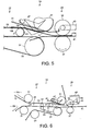
- FIG. 5 shows the construction of reverse controller 19 in the reverse operation.
- the component elements of reverse controller 19 shown in FIG. 5 are the same as those of an apparatus shown in FIG. 3 and the explanations of common elements will be omitted.
- FIG. 5 shows the state that the front end 12a of sheet 12 is held between normal/reverse rotation roller 37 and pitch roller 39 and normal/reverse rotation roller 37 starts the accelerating operation.
- a portion of sheet 12 from the rear end 12b to 12c in the vicinity of the exit of conveyor in a main body 27 is held by conveyor belt 33. Therefore, even when normal/reverse rotation roller 37 holding the front end 12a starts to accelerate, the portion of sheet 12 from the rear end 12b to 12c in the vicinity of the exit of conveyor in a main body 27 is held by conveyor belt 33 and becomes a resistance and the stop position of sheet 12 shifts to the upstream side in the conveying direction (the left side in FIG. 5).
- FIG. 6 is a diagram showing the entire structure of reverse controller 19 in the first embodiment of the present invention.
- a driving roller 49 having a driving source independent from conveying unit 14 is provided to the conveying path for conveying sheets 12 after converse and a pinch roller 51 is provided at a position opposite to this driving roller 49 when compared with the basic structure shown in FIG. 3.
- a shift sensor 53 that acts as a trigger to operate driving roller 49 is provided at the upstream side in the conveying direction upper than driving roller 49.
- the shift sensor 53 detects the front and rear ends of sheet 12 and monitors a gap between sheets 12. Further, shift sensor 53 detects the front end of sheet 12 and monitors a pitch between sheets.
- FIG. 7 is a sectional view of driving roller 49, pinch roller 51 and conveying belt 33 shown in FIG. 6 viewed from the conveying direction. As shown in FIG. 7, a pair of driving rollers 49 and pinch rollers 51 is provided both sides of conveying belt 33.
- Driving roller 49 rotates normally at the same peripheral velocity as the conveying velocity of conveying belt 33 and does not change the conveying velocity of conveyed sheets 12.
- Shift sensor 53 detects a gap (or a pitch) between a sheet 12 reversed by reverse controller 19 and another sheet conveyed at the downstream side in the conveying direction of this sheet 12. Based on the result of this detection, when a gap (or a pitch) becomes short, driving roller 49 and pinch roller 51 decelerate at a moment when they hold a sheet 12 and decelerate a sheet 12 and a gap (or a pitch) with another sheet 12 being conveyed at the downstream side in the conveying direction is corrected to a proper length.
- reversed sheet 12 is held on conveying belt 33.
- the conveying path is straight through and its holding force is small and when a pinching pressure of pinch roller 51 is made moderately larger than the holding force of conveying belt 33, it becomes possible to correct a gap properly.
- change in gap (or pitch) of sheets 12 after reversed by reverse controller 19 can be resolved by correcting a gap (or pitch) not only when a gap (or pitch) becomes short but also when it becomes long.
- FIG. 8 is a diagram showing the construction of reverse controller 19 in the second embodiment. Explanations of component elements common to those of reverse controller 19 shown in FIG. 3 will be omitted.
- driving roller 57 to convey sheet 12 pinch roller 59 arranged at a position opposite to this driving roller 57 to give a pinch pressure to sheet 12 and guides 41, 41, 41, and 41 to lead sheet 12 to reverse unit 29 are provided at an exit 55 in main body conveyor immediately before reverse unit 29.
- Driving roller 57 receives a driving force from conveying unit 14 of sheet processing apparatus 1 and rotates at the same peripheral velocity as the conveying velocity of conveying unit 14. Further, driving roller 57 is equipped with a one-way clutch that freely rotates only in the direction to which sheet 12 is pulled out. Therefore, when a sheet 12 is pulled out in a moment when normal/reverse rotation roller 37 and pinch roller 39 hold sheet 12, the rear end of sheet 12 does not resist even when it remains in the vicinity of exit in main body conveyor.
- sheet 12 conveyed through entrance side 19a is held by normal/reverse rotation roller 37 and pinch roller 39 at its front end and pulled out to reverse unit 29 side as accelerated.
- the rear end of sheet 12 is held between driving roller 57 and pinch roller 59.
- it escapes in the pulled-out direction by one-way clutch of driving roller 57 and therefore, it is free from resistance by being held by driving roller 57 and pinch roller 59.
- Driving roller 57 and pinch roller 59 are one set but it is not necessary to restrict especially and plural sets may be installed according to the shape of conveying unit 14 or other conditions.
- FIG. 9 and FIG. 10 show the structure of reverse controller 19 in a third embodiment of the present invention. Explanation of component elements common to those of reverse controller 19 shown in FIG. 3 will be omitted.
- a swingable tension roller 61 equipped with an independent motor driving source is provided in conveying unit 14 at the upstream side from reverse unit 29 of reverse controller 19. Swingable tension roller 61 is normally pressed by conveying belt 33 at the upper stream side in the conveying direction of exit in main body conveyor 55 as shown in FIG. 9 and a holding force to sheet 12 is generated in conveying belt 33.
- swingable tension roller 61 is separated from conveying belt 33 as shown in FIG. 10. Therefore, exit in main body conveyor 55 is released from the thrust pressure of swingable tension roller 61 and the holding force of belt 33 decreases.
- FIG. 11 shows the construction of sheet processing apparatus 1 involved in a fourth embodiment of the present invention.
- Conveying unit 14 from entrance side 19a of reverse controller 19 to exit in main body conveyor 55 is composed of shift sensors 35 and plural rollers described later, etc.
- These plural rollers are composed of driving rollers 63 and 63 which rotate at the same conveying velocity as conveying unit 14 of sheet processing apparatus 1, an acceleration drive roller 65 which rotates at a conveying velocity faster than driving rollers 63, and pinch rollers 67, 67 and 67 which are arranged opposing to drive rollers 63 and 63 and acceleration drive roller 65 and give pinch pressure. Further, guides 41, 41, 41 and 41 are provided to lead sheet 12 to reverse unit 29.
- Sheet 12 is accelerated every time when passes drive rollers 63 and 63 and acceleration drive roller 65.
- Drive rollers 63 and 63 are provided with a one-way clutch and accelerate the conveying velocity of sheet 12 without receiving a resistance.
- FIG. 12 is a graph showing the control of the peripheral velocity V (conveying velocity) of normal/reverse rotation roller 37 of reverse controller 19 in a fourth embodiment of the present invention.
- the axis of abscissas of the graph shows a time T (s), and the axis of ordinate shows a peripheral velocity (a conveying velocity) V (m/s) of normal/reverse rotation roller 37.
- the peripheral velocity V0 of normal/reverse rotation roller is almost the same velocity as the conveying velocity of conveying unit 14.
- the peripheral velocity is changed properly according to various characteristic amounts such as size, stiffness, weight, etc. of sheet 12 that is conveyed and not particularly restricted.
- shift sensors 35 detect the rear end of sheet 12
- normal/reverse rotation roller 37 starts to decelerate after a specified time from the detected time (t11) and stops to rotate (t12). At this time, it becomes possible to make the rear end positions of sheets 12 (or the front end after reversed) uniform at the same deceleration curve irrespective of the length of sheet 12 in the conveying direction.
- acceleration drive roller 65 and pinch roller 67 are not restricted to be one set but plural sets of acceleration drive rollers 65 equipped with a one-way clutch may be provided so as to accelerate in stages.
- acceleration drive rollers 65 may be constructed with drive rollers equipped with a one-way clutch so as to accelerate normal/reverse rotation roller 37 in a moment when it holds sheet 12. At this time, the conveying velocity of normal/reverse rotation roller 37 is so controlled as shown in FIG. 4. According to the modification of the fourth embodiment, when normal/reverse rotation roller 37 pulls out sheet 12, acceleration drive roller 65 and pinch roller 67 do not resist and therefore, it becomes possible to reduce change in gear or pitch of sheet 12 and generation of jamming before and after the reverse operation.
- the sheet reverse device (reverse controller) of the present invention has the structure and actions as described above and is capable of reducing generation of jamming by reducing change in gap or pitch between sheets before and after the sheet reversing operation.
Landscapes
- Engineering & Computer Science (AREA)
- Mechanical Engineering (AREA)
- Separation, Sorting, Adjustment, Or Bending Of Sheets To Be Conveyed (AREA)
- Delivering By Means Of Belts And Rollers (AREA)
- Sorting Of Articles (AREA)
Abstract
Description
- FIG. 1
- is a block diagram showing a control system of a controller involved in the embodiment of the present invention;
- FIG. 2
- is a block diagram showing the construction of sheet processing device involved in the embodiment of the present invention;
- FIG. 3
- is a basic construction diagram of the sheet reverse device involved in respective embodiments;
- FIG. 4
- is a graph showing the operation of the normal/reverse rotation roller of the basic construction of the reverse controller shown involved in the first through third embodiments of the present invention and FIG. 3;
- FIG. 5
- is a schematic diagram showing the operation of the sheet reverse device in the reverse operation;
- FIG. 6
- is a schematic diagram showing the construction of the sheet reverse device involved in the first embodiment;
- FIG. 7
- is a sectional view of a driving roller, a pinch roller and a conveying belt involved in the first embodiment of the present invention;
- FIG. 8
- is a schematic diagram showing the construction of the sheet reverse device involved in the second embodiment of the present invention;
- FIG. 9
- is a schematic diagram showing the construction of the sheet reverse device involved in the third embodiment of the present invention;
- FIG. 10
- is a schematic diagram showing the construction of the sheet reverse device involved in the third embodiment of the present invention;
- FIG. 11
- is a schematic diagram showing the construction of the sheet reverse device involved in the fourth embodiment of the present invention; and
- FIG. 12
- is a graph showing the operation of the normal/reverse rotation roller involved in the fourth embodiment of the present invention.
Claims (12)
- A sheet reverse device comprising:first conveying means (31, 33) for conveying a sheet in a first direction;a reverse unit (29) to reverse the sheet conveyed from the first conveying means in a second direction differing from the first direction;second conveying means (31, 33, 49, 51) for conveying the sheet reversed in the reverse unit in the second direction;a sensor (53) provided on the second conveying means to detect the sheet;calculation means (2, 4, 5) for calculating a space between the sheets based on the detected result of the sensor; anda controller (2, 4, 5) adapted to control the conveying velocity of the second conveying unit so as to decelerate the conveying velocity of the sheet when the space between the sheets is shorter than a specified value and accelerate the conveying velocity of the sheets when a space between the sheets is longer than a specified value.
- The device as set force in claim 1, wherein the sensor (53) detects a front end of the sheet and a rear end of the sheet conveyed preceding to the next sheet,
the calculating means calculates a gap and/or a pitch between the sheets based on the result of detection by the sensor. - The device as set force in claim 1 or 2, wherein the reverse unit includes a normal/reverse rotation roller (37) capable of rotating in a normal/reverse direction and a pinch roller (39) arranged opposing to the normal/reverse rotation roller, the normal/reverse rotation roller rotating in the normal direction and taking the sheet conveyed from the first conveying means and then, the normal/reverse rotation roller rotating in the reverse direction and conveying the taken sheet in the second direction differing from the first direction.
- The device as set force in one of claims 1 to 3, wherein the second conveying unit includes a driving roller (49) and a pinch roller (51) arranged opposing to the driving roller so as to hold the sheet, the controller controlling the rotating velocity of the driving roller based on the result of calculation by the calculating means.
- A sheet reverse device comprising:first conveying means (31, 33) for holding and conveying a sheet in a first direction;a reverse unit (29) to reverse the sheet conveyed from the first conveying means in a second direction differing from the first direction;second conveying means (31, 33) for conveying the sheet reversed in the reverse unit in the second direction; andresistance reducing means (57, 59; 61; 63, 65, 67) provided on the first conveying means for reducing a conveying resistance resulting from the holding of the sheet by the first conveying means when the sheet is conveyed to the reverse unit from the first conveying means.
- The sheet reverse device as set force in claim 5, wherein the reverse unit includes a normal/reverse rotation roller (37) capable of rotating in a normal/reverse direction and a pinch roller (39) arranged opposing to the normal/reverse rotation roller, the normal/reverse rotation roller rotating in the normal direction and taking the sheet by accelerating the conveying velocity of the sheet conveyed from the first conveying means and then, rotating in the reverse direction and conveying the taken sheet in the second direction differing from the first direction.
- The sheet reverse device as set force in claim 5 or 6, wherein the resistance reducing means includes a one-way clutch that is rotated and driven only in the first direction.
- A sheet reverse device comprising:a conveying roller (57; 63, 65) equipped with a one-way clutch that is rotated and driven only in a first direction to convey a sheet in a first conveying direction;a reverse unit (29) to take the sheet from the conveying rollers with a normal/reverse rotation roller (37) capable of rotating in a normal/reverse direction and a pinch roller (39) provided opposing to the normal/reverse rotation roller while accelerating the conveying velocity of the sheet and convey in a second direction differing from the first direction; andconveying means (31, 33) for conveying the sheet conveyed from the reverse unit in the second direction.
- A sheet reverse device comprising:a conveying belt (33) to hold and convey a sheet in a first direction;holding force adjusting means (61) provided to the conveying belt detachably for increasing a holding force of the conveying belt to hold the sheet by contacting the conveying belt and decreasing the holding force of the conveying belt to hold the sheet by getting away from the conveying belt;a reverse unit (29) to take in the sheet conveyed from the conveying belt while accelerating the conveying velocity of the sheet by a normal/reverse rotation roller (37) capable of rotating in the normal/reverse direction and convey the sheet in a second direction differing from the first direction;conveying means (31, 33) for conveying the sheet conveyed from the reverse unit in the second direction; anda controller (2, 4, 5) to control the holding force adjusting means so as to reduce the holding force of the conveying belt by operating the holding force adjusting means.
- A sheet reverse device comprising:a conveying roller (63) equipped with a one-way clutch that is rotated and driven in a first direction only to convey a sheet in a first direction at a first conveying velocity;an acceleration drive roller (65) to convey the sheet conveyed from the conveying roller in the first direction at a second conveying velocity faster than the first conveying velocity;a reverse unit (29) to take the sheet conveyed from the acceleration drive roller at the second conveying velocity by a normal/reverse rotation roller capable of rotating in a normal/reverse direction and a pinch roller provided opposing to the normal/reverse rotation roller and convey in a second direction differing from the first direction; andconveying means for conveying the sheet conveyed from the reverse unit in the second direction.
- The sheet reverse device as set force in Claim 10 further comprising:a sensor (35) provided at the upper stream side in the conveying direction from the reverse unit to detect a rear end of the sheet,wherein the reverse unit decelerates the conveying velocity of the sheet and stops the sheet based on the detection result of the sensor.
- The sheet reverse device as set force in Claim 10 or 11, wherein the acceleration drive roller (65) is equipped with a one-way clutch that is rotated and driven in a first direction only, and
the reverse unit (29) accelerates the sheet that is conveyed by the acceleration drive roller to a third conveying velocity faster than the second conveying velocity.
Applications Claiming Priority (2)
| Application Number | Priority Date | Filing Date | Title |
|---|---|---|---|
| JP2003319964A JP2005082394A (en) | 2003-09-11 | 2003-09-11 | Paper sheet reversal control device |
| JP2003319964 | 2003-09-11 |
Publications (2)
| Publication Number | Publication Date |
|---|---|
| EP1514822A2 true EP1514822A2 (en) | 2005-03-16 |
| EP1514822A3 EP1514822A3 (en) | 2005-04-20 |
Family
ID=34132036
Family Applications (1)
| Application Number | Title | Priority Date | Filing Date |
|---|---|---|---|
| EP04020148A Withdrawn EP1514822A3 (en) | 2003-09-11 | 2004-08-25 | Sheet reverse device |
Country Status (4)
| Country | Link |
|---|---|
| US (1) | US20050067765A1 (en) |
| EP (1) | EP1514822A3 (en) |
| JP (1) | JP2005082394A (en) |
| KR (1) | KR100621278B1 (en) |
Cited By (2)
| Publication number | Priority date | Publication date | Assignee | Title |
|---|---|---|---|---|
| EP1705144B1 (en) * | 2005-03-22 | 2013-07-31 | Kabushiki Kaisha Toshiba | Apparatus for processing paper sheets and method of processing paper sheets |
| CN114308733A (en) * | 2021-12-23 | 2022-04-12 | 常州市同裕塑件有限公司 | Cut circle with detecting integrative equipment of pile |
Families Citing this family (5)
| Publication number | Priority date | Publication date | Assignee | Title |
|---|---|---|---|---|
| JP4602196B2 (en) * | 2005-08-16 | 2010-12-22 | 株式会社東芝 | Paper sheet processing equipment |
| JP2007246261A (en) | 2006-03-17 | 2007-09-27 | Toshiba Corp | Switchback mechanism, switchback device, and switchback method |
| US8016282B2 (en) * | 2007-12-21 | 2011-09-13 | Pitney Bowes Inc. | Transport for singulating items |
| JP4510899B2 (en) * | 2008-01-11 | 2010-07-28 | シャープ株式会社 | Sheet conveying apparatus, document processing apparatus and image forming apparatus using the same |
| JP2017186132A (en) * | 2016-04-06 | 2017-10-12 | 沖電気工業株式会社 | Medium processor |
Family Cites Families (22)
| Publication number | Priority date | Publication date | Assignee | Title |
|---|---|---|---|---|
| US3724657A (en) * | 1970-05-16 | 1973-04-03 | Nippon Electric Co | Switching device for delivering sheet-like articles |
| US3734490A (en) * | 1971-11-29 | 1973-05-22 | J Parks | Document feeding mechanism |
| JPS5139382B2 (en) * | 1972-02-17 | 1976-10-27 | ||
| JPS5522381B2 (en) * | 1972-10-05 | 1980-06-17 | ||
| JPH0825695B2 (en) * | 1986-05-30 | 1996-03-13 | 日立工機株式会社 | Duplex printing device |
| US5129642A (en) * | 1988-06-02 | 1992-07-14 | Bell & Howell Company | Controllable document drive and separation system |
| JPH072409A (en) * | 1993-05-06 | 1995-01-06 | Licentia Patent Verwalt Gmbh | Shifting device of flat sent article |
| US5887868A (en) * | 1993-12-09 | 1999-03-30 | Xerox Corporation | Drive system for rollers |
| JP2718358B2 (en) * | 1994-02-23 | 1998-02-25 | 日本電気株式会社 | Paper sheet turning device |
| US5461468A (en) * | 1994-10-31 | 1995-10-24 | Xerox Corporation | Document handler interdocument gap control system |
| US5575466A (en) * | 1994-11-21 | 1996-11-19 | Unisys Corporation | Document transport with variable pinch-roll force for gap adjust |
| US5689795A (en) * | 1996-09-24 | 1997-11-18 | Xerox Corporation | Sheet transfer apparatus with adaptive speed-up delay |
| JP3889188B2 (en) * | 1998-09-11 | 2007-03-07 | 株式会社リコー | Automatic document feeder |
| JP3548449B2 (en) * | 1999-02-01 | 2004-07-28 | キヤノン株式会社 | Sheet conveying device and image forming apparatus provided with the device |
| US6322069B1 (en) * | 1999-03-12 | 2001-11-27 | Xerox Corporation | Interpaper spacing control in a media handling system |
| EP1785954B1 (en) * | 2000-03-23 | 2016-11-30 | Kabushiki Kaisha Toshiba | Reversing and aligning mechanism for sheet processing apparatus |
| JP4477740B2 (en) * | 2000-04-20 | 2010-06-09 | 東芝テック株式会社 | Sheet conveying apparatus and image reading apparatus |
| JP3493336B2 (en) * | 2000-08-18 | 2004-02-03 | スター精密株式会社 | Paper ejection device and printer |
| US6533264B1 (en) * | 2001-02-09 | 2003-03-18 | Unisys Corporation | Constant space document feeder |
| JP4532788B2 (en) * | 2001-07-25 | 2010-08-25 | キヤノン株式会社 | Sheet transport device |
| JP4145638B2 (en) * | 2002-11-27 | 2008-09-03 | 株式会社東芝 | Paper sheet inversion control device and paper sheet inversion control method |
| JP4256251B2 (en) * | 2003-12-17 | 2009-04-22 | 株式会社東芝 | Paper sheet direction reversing device and paper sheet stamping device |
-
2003
- 2003-09-11 JP JP2003319964A patent/JP2005082394A/en active Pending
-
2004
- 2004-08-17 US US10/919,509 patent/US20050067765A1/en not_active Abandoned
- 2004-08-25 EP EP04020148A patent/EP1514822A3/en not_active Withdrawn
- 2004-09-09 KR KR1020040072057A patent/KR100621278B1/en not_active Expired - Fee Related
Cited By (3)
| Publication number | Priority date | Publication date | Assignee | Title |
|---|---|---|---|---|
| EP1705144B1 (en) * | 2005-03-22 | 2013-07-31 | Kabushiki Kaisha Toshiba | Apparatus for processing paper sheets and method of processing paper sheets |
| CN114308733A (en) * | 2021-12-23 | 2022-04-12 | 常州市同裕塑件有限公司 | Cut circle with detecting integrative equipment of pile |
| CN114308733B (en) * | 2021-12-23 | 2023-11-28 | 常州市同裕塑件有限公司 | Cut circle with detecting integrative equipment of pile |
Also Published As
| Publication number | Publication date |
|---|---|
| JP2005082394A (en) | 2005-03-31 |
| EP1514822A3 (en) | 2005-04-20 |
| US20050067765A1 (en) | 2005-03-31 |
| KR100621278B1 (en) | 2006-09-19 |
| KR20050027028A (en) | 2005-03-17 |
Similar Documents
| Publication | Publication Date | Title |
|---|---|---|
| US20100314217A1 (en) | Posture converting device and paper-like material processing apparatus | |
| JP4361821B2 (en) | Paper sheet skew correction device and banknote deposit and withdrawal device | |
| JP2002193517A (en) | Paper processing equipment | |
| US20110074088A1 (en) | Paper sheet pick up device | |
| EP1514822A2 (en) | Sheet reverse device | |
| US20070267807A1 (en) | Sheet processing apparatus and sheet processing method | |
| EP2843631B1 (en) | Sheet discriminating device and sheet processing apparatus | |
| KR100858380B1 (en) | Switchback mechanism, switchback apparatus, and switchback method | |
| US8596634B2 (en) | System for controlling a singulating belt in a mailpiece feeder | |
| CN107437296B (en) | Active paper spacing adjustment device and method | |
| JP3746144B2 (en) | Paper sorter | |
| JP4300072B2 (en) | Paper sheet pitch correction device | |
| US8596635B2 (en) | System for controlling mailpiece conveyance in a mailpiece feeder | |
| JP3368351B2 (en) | Paper sheet transport device and paper sheet stacking device | |
| JPH0438652B2 (en) | ||
| JP2576213B2 (en) | Paper feeding mechanism | |
| JP2005162407A (en) | Paper sheet weight detection device | |
| JP2003292176A (en) | Paper unloading and conveying device | |
| JPH05319682A (en) | Transport control method and apparatus | |
| JP3275692B2 (en) | Paper processing equipment | |
| JPH01176751A (en) | Skew correcting method | |
| JPH1119595A (en) | Mail interval adjusting device, mail interval adjusting method, and mail sorting / stacking device | |
| JP2003292201A (en) | Paper processing equipment | |
| JPH02163226A (en) | Mechanism for delivering paper sheet | |
| JPH01197252A (en) | Sheet overlapped-feeding detector |
Legal Events
| Date | Code | Title | Description |
|---|---|---|---|
| PUAI | Public reference made under article 153(3) epc to a published international application that has entered the european phase |
Free format text: ORIGINAL CODE: 0009012 |
|
| PUAL | Search report despatched |
Free format text: ORIGINAL CODE: 0009013 |
|
| 17P | Request for examination filed |
Effective date: 20040825 |
|
| AK | Designated contracting states |
Kind code of ref document: A2 Designated state(s): AT BE BG CH CY CZ DE DK EE ES FI FR GB GR HU IE IT LI LU MC NL PL PT RO SE SI SK TR |
|
| AX | Request for extension of the european patent |
Extension state: AL HR LT LV MK |
|
| AK | Designated contracting states |
Kind code of ref document: A3 Designated state(s): AT BE BG CH CY CZ DE DK EE ES FI FR GB GR HU IE IT LI LU MC NL PL PT RO SE SI SK TR |
|
| AX | Request for extension of the european patent |
Extension state: AL HR LT LV MK |
|
| AKX | Designation fees paid |
Designated state(s): DE FR GB IT SE |
|
| 17Q | First examination report despatched |
Effective date: 20070515 |
|
| STAA | Information on the status of an ep patent application or granted ep patent |
Free format text: STATUS: THE APPLICATION IS DEEMED TO BE WITHDRAWN |
|
| 18D | Application deemed to be withdrawn |
Effective date: 20080226 |