EP1514799B1 - Method for attitude determination of spacecraft using a direction vector and a total momentum measurement - Google Patents
Method for attitude determination of spacecraft using a direction vector and a total momentum measurement Download PDFInfo
- Publication number
- EP1514799B1 EP1514799B1 EP04020693A EP04020693A EP1514799B1 EP 1514799 B1 EP1514799 B1 EP 1514799B1 EP 04020693 A EP04020693 A EP 04020693A EP 04020693 A EP04020693 A EP 04020693A EP 1514799 B1 EP1514799 B1 EP 1514799B1
- Authority
- EP
- European Patent Office
- Prior art keywords
- vector
- spacecraft
- coordinate system
- angular momentum
- determination
- Prior art date
- Legal status (The legal status is an assumption and is not a legal conclusion. Google has not performed a legal analysis and makes no representation as to the accuracy of the status listed.)
- Expired - Lifetime
Links
- 239000013598 vector Substances 0.000 title claims description 98
- 238000000034 method Methods 0.000 title claims description 32
- 238000005259 measurement Methods 0.000 title claims description 12
- 239000011159 matrix material Substances 0.000 claims description 15
- 230000009466 transformation Effects 0.000 claims description 13
- 230000001902 propagating effect Effects 0.000 claims description 7
- 230000000644 propagated effect Effects 0.000 claims description 2
- 230000008901 benefit Effects 0.000 description 3
- 230000008569 process Effects 0.000 description 3
- 230000008878 coupling Effects 0.000 description 2
- 238000010168 coupling process Methods 0.000 description 2
- 238000005859 coupling reaction Methods 0.000 description 2
- 238000010586 diagram Methods 0.000 description 2
- 230000002123 temporal effect Effects 0.000 description 2
- 230000002730 additional effect Effects 0.000 description 1
- 230000008859 change Effects 0.000 description 1
- 230000003287 optical effect Effects 0.000 description 1
- 230000002787 reinforcement Effects 0.000 description 1
- 210000002023 somite Anatomy 0.000 description 1
Images

Classifications
-
- B—PERFORMING OPERATIONS; TRANSPORTING
- B64—AIRCRAFT; AVIATION; COSMONAUTICS
- B64G—COSMONAUTICS; VEHICLES OR EQUIPMENT THEREFOR
- B64G1/00—Cosmonautic vehicles
- B64G1/22—Parts of, or equipment specially adapted for fitting in or to, cosmonautic vehicles
- B64G1/24—Guiding or controlling apparatus, e.g. for attitude control
- B64G1/36—Guiding or controlling apparatus, e.g. for attitude control using sensors, e.g. sun-sensors, horizon sensors
-
- B—PERFORMING OPERATIONS; TRANSPORTING
- B64—AIRCRAFT; AVIATION; COSMONAUTICS
- B64G—COSMONAUTICS; VEHICLES OR EQUIPMENT THEREFOR
- B64G1/00—Cosmonautic vehicles
- B64G1/22—Parts of, or equipment specially adapted for fitting in or to, cosmonautic vehicles
- B64G1/24—Guiding or controlling apparatus, e.g. for attitude control
- B64G1/28—Guiding or controlling apparatus, e.g. for attitude control using inertia or gyro effect
- B64G1/285—Guiding or controlling apparatus, e.g. for attitude control using inertia or gyro effect using momentum wheels
-
- B—PERFORMING OPERATIONS; TRANSPORTING
- B64—AIRCRAFT; AVIATION; COSMONAUTICS
- B64G—COSMONAUTICS; VEHICLES OR EQUIPMENT THEREFOR
- B64G1/00—Cosmonautic vehicles
- B64G1/22—Parts of, or equipment specially adapted for fitting in or to, cosmonautic vehicles
- B64G1/24—Guiding or controlling apparatus, e.g. for attitude control
- B64G1/26—Guiding or controlling apparatus, e.g. for attitude control using jets
-
- B—PERFORMING OPERATIONS; TRANSPORTING
- B64—AIRCRAFT; AVIATION; COSMONAUTICS
- B64G—COSMONAUTICS; VEHICLES OR EQUIPMENT THEREFOR
- B64G1/00—Cosmonautic vehicles
- B64G1/22—Parts of, or equipment specially adapted for fitting in or to, cosmonautic vehicles
- B64G1/24—Guiding or controlling apparatus, e.g. for attitude control
- B64G1/36—Guiding or controlling apparatus, e.g. for attitude control using sensors, e.g. sun-sensors, horizon sensors
- B64G1/365—Guiding or controlling apparatus, e.g. for attitude control using sensors, e.g. sun-sensors, horizon sensors using horizon or Earth sensors
-
- B—PERFORMING OPERATIONS; TRANSPORTING
- B64—AIRCRAFT; AVIATION; COSMONAUTICS
- B64G—COSMONAUTICS; VEHICLES OR EQUIPMENT THEREFOR
- B64G1/00—Cosmonautic vehicles
- B64G1/22—Parts of, or equipment specially adapted for fitting in or to, cosmonautic vehicles
- B64G1/24—Guiding or controlling apparatus, e.g. for attitude control
- B64G1/36—Guiding or controlling apparatus, e.g. for attitude control using sensors, e.g. sun-sensors, horizon sensors
- B64G1/366—Guiding or controlling apparatus, e.g. for attitude control using sensors, e.g. sun-sensors, horizon sensors using magnetometers
Definitions
- the object of the present invention is therefore to provide a simplified and improved method for determining the position of a spacecraft, in particular a three-axis-stabilized spacecraft. This object is solved by the features of claims 1 and 5.
- the invention relates to a method for determining the attitude of a spacecraft based on the determination of direction vectors and spin vectors, wherein sensor data and spin data are determined as output variables for determining the position, wherein the first vector determination is a measurement of a direction vector in a body-fixed coordinate system with the aid of a sensor, the second vector determination is the determination of a reference direction vector in a reference coordinate system on the basis of the orbital position of the spacecraft and an orbit model, the third vector determination determines the total spin vector of the spacecraft in the body-fixed coordinate system, is determined as the fourth vector determination of the reference total spin vector of the spacecraft in a reference coordinate system by temporally propagating known initial values of the total spin of the spacecraft or by temporally tracking a reference model for the total spin and Based on the four vectors, a determination of the position of the spacecraft takes place.
- the total spin can be determined, for example, as a deviation from a reference total spin.
- the reference total spin can be determined on the one hand by temporal propagation of known initial values of the total spin. Therefore, a measurement or estimation of the total spin at a certain starting time is required.
- the reference direction vector can also be determined-analogously to the reference total spin-either by temporally propagating known initial values of the direction vector or by temporally tracking a reference model for the direction vector.
- a specific embodiment of the method according to the invention provides that, as an intermediate step for determining the position, first the rotational speed or a part of the rotational speed between a body-fixed coordinate system and the reference coordinate system is determined.
- the reference direction vector and a temporally propagated from known initial values or temporally tracked by a reference model total spin initially the Leksraten portion of the rotational speed or the rotational speed vector in the direction of the direction vector between the body-fixed coordinate system and the reference Coordinate system is determined.
- the total spin can be used in a suitable representation, for example in an orbit coordinate system. With the help of the longitudinal rate component, the total spin vector is determined in the body-fixed coordinate system.
- a transformation matrix is determined which describes the deviations of the actual position of the body-fixed coordinate system of the spacecraft from the reference position of the body-fixed coordinate system representing reference coordinate system, ie a transformation matrix of the deviations of the actual position of the body coordinate system of the spacecraft from the reference coordinate system determined.
- the reference coordinate system thus represents the desired position of the body-fixed coordinate system.
- the total spin is used. It is therefore necessary for the entire orientation only the knowledge of the direction vector and the total spin, which greatly simplifies the process. Moreover, in the last method step, it is not the total twist required in direction and magnitude that suffices for the direction of the total spin alone.
- At least the direction vector and the reference direction vector are additionally used in particular.
- the overall spin is essentially determined by whether the spacecraft has spin wheels whose wheel spin constitutes an essential component of the total spin.
- the method described so far can also be carried out on a spacecraft with twisting wheels without an explicit measurement of the wheel spin. It is then possible additionally to determine the rotational speed or portions of the rotational speed on the basis of estimated values or measured values for the wheel spin.
- the determination of the longitudinal rate component and the determination of the total spin vector can thus additionally be carried out on the basis of the determined spin vector of spiral wheels of the spacecraft.
- the arrangements mentioned can consist of one or more functional components. Such an arrangement is used in particular for carrying out the o.g. Process. There are also here already o.g. Advantages and possibilities.
- a further development of the arrangement according to the invention additionally comprises: a device for determining the longitudinal rate component of the rotational speed or of the rotational speed vector in the direction of the direction vector between the body-fixed coordinate system and the reference coordinate system.
- the arrangement according to the invention can have a device for measuring or estimating the swirl vector of swirl wheels of the spacecraft.
- the essential advantage of the described method is that, irrespective of the time-variant desired orientation with respect to the orbit system (for example in so-called yaw steering), all computation steps remain unchanged since only the matrix T R0 is selected accordingly.
- extensive calculations for compensation terms or even time-variable dynamics for the observer are accepted.
- sensors eg earth sensor, magnetometer
- FIG. 1 shows as a specific embodiment a block diagram of components that can be used to implement the method described here:
- the reference unit vector e o is determined with the aid of a stored orbit model in a first orbital model device 1 and fed to a device for longitudinal rate determination 2 for determining c according to equation (4).
- this device 2 is also the means of the known, stored transformation matrix T RO by a transformation device 3, transformed into the reference system unit vector e R , and its time derivative, obtained via the differentiator 4, respectively.
- the unit vector e R is further fed into the swirl determination module 5, as well as into the position determination module 6.
- the unit vector e B is determined and fed to the modules for longitudinal rate determination 2, for swirl determination 5, and for position determination 6, using a sensor 9 (eg, earth sensor, magnetometer) shown in FIG.
- a sensor 9 eg, earth sensor, magnetometer
- the two first-mentioned modules, the derivative of a differentiator 7, derived time derivative of e B is also supplied.
- the swirl vector of the wheels, h w won. This is fed into the modules for longitudinal rate determination 2 and for swirl determination 5.
- the longitudinal rate c determined in module 2 is fed to the swirl determination module 5, the result of which, h B , is in turn fed into the position determining module 6 and into a reference model module for the orbital swirl 8.
- This reference model module 8 is also supplied with estimates i for external disturbance torques.
Landscapes
- Engineering & Computer Science (AREA)
- Remote Sensing (AREA)
- Chemical & Material Sciences (AREA)
- Combustion & Propulsion (AREA)
- Radar, Positioning & Navigation (AREA)
- Aviation & Aerospace Engineering (AREA)
- Navigation (AREA)
Description
Die vorliegende Erfindung betrifft ein Verfahren zur Lagebestimmung eines Raumfahrzeuges basierend auf zwei Vektorbestimmungen, wobei Sensordaten und Dralldaten als Ausgangsgrößen zur Lagebestimmung ermittelt werden.The present invention relates to a method for determining the attitude of a spacecraft based on two vector determinations, wherein sensor data and spin data are determined as output variables for position determination.
Aus dem Stand der Technik sind Verfahren bekannt, mit denen ein Raumfahrzeug, ausgerüstet mit einem Erdsensor (= Richtungsmessung) und Drallrädern, die einen Drall-Sollwert erzeugen, um alle 3 Achsen stabilisiert werden kann (z. B. Whecon-Prinzip).From the prior art methods are known, with which a spacecraft, equipped with an earth sensor (= direction measurement) and swirl wheels, which produce a swirl target value, can be stabilized around all 3 axes (eg Whecon principle).
All diese Verfahren nutzen die dynamische Kopplung zwischen Rollen und Gieren, hervorgerufen durch den Drall-Sollwert aus, um entweder direkt durch entsprechend gewählte Aktuatoransteuerung (Düsen oder Räder) oder durch Einsatz eines Beobachters zur Ermittlung der fehlenden Lageinformation (in der Regel die Gierlage) das Raumfahrzeug zu stabilisieren.All of these methods utilize the dynamic coupling between rolls and yaw caused by the swirl setpoint to either directly through appropriately selected actuator control (nozzles or wheels) or by using an observer to determine the missing attitude information (typically the yaw attitude) To stabilize spacecraft.
Hierzu wird beispielhaft auf EP 0 785 132 verwiesen. Dort wird einerseits das Whecon-Prinzip erläutert, andererseits wird ein Verfahren zur Lagebestimmung eines Raumfahrzeuges beschrieben, bei dem eine Entkopplung der einzelnen Momente erfolgt, die auf das Raumfahrzeug einwirken. Es werden dort also Entkopplungsterme bestimmt, um eine Entkopplung der Roll-Gier-Kopplungsterme zu erzielen. Dies stellt jedoch einen relativ hohen Rechenaufwand dar.Reference is made by way of example to EP 0 785 132. There, on the one hand, the Whecon principle is explained, on the other hand, a method for determining the attitude of a spacecraft is described, in which a decoupling of the individual moments takes place, which act on the spacecraft. Decoupling terms are therefore determined there in order to achieve a decoupling of the roll-yaw coupling terms. However, this represents a relatively high computational effort.
Aus US 6,282,467 ist ein System und ein Verfahren zur Bestimmung der Lage eines spinstabilisierten Raumfahrzeuges in einem inertialen Koordinatensystem bekannt. Dabei werden folgende Schritte durchgeführt: Bestimmung einer Drallvektorrichtung in dem inertialen Koordinatensystem auf Basis von Messdaten, insbesondere Sensordaten; Bestimmung einer Drallvektorrichtung in einem körperfesten Koordinatensystem auf Basis bekannter Trägheitsdaten; Bestimmung eines Richtungsvektors aus einachsigen Sensordaten; Bestimmung eines Referenz-Richtungsvektors mit Hilfe eines Ephemeridenmodells; Bestimmung der Lage des Raumfahrzeuges aus den genannten vier Vektoren und Propagation der Lage unter Benutzung von Sensordaten. Dieses Verfahren ist für dreiachsenstabilisierte Raumfahrzeuge nicht anwendbar und erfordert überdies eine relativ große Zahl bekannter Eingangsgrößen und Sensordaten.From US 6,282,467 a system and a method for determining the position of a spin-stabilized spacecraft in an inertial coordinate system is known. The following steps are carried out: determination of a spin vector direction in the inertial coordinate system on the basis of measured data, in particular sensor data; Determining a spin vector direction in a body-fixed coordinate system based on known inertial data; Determination of a direction vector from uniaxial sensor data; Determination of a reference direction vector with the help of an ephemeris model; Determining the position of the spacecraft from said four vectors and propagating the location using sensor data. This method is not applicable to three-axis stabilized spacecraft and moreover requires a relatively large number of known inputs and sensor data.
Aufgabe der vorliegenden Erfindung ist es daher, ein vereinfachtes und verbessertes Verfahren zur Lagebestimmung eines Raumfahrzeuges, insbesondere eines dreiachsen-stabilisierten Raumfahrzeuges, bereitzustellen. Diese Aufgabe wird gelöst durch die Merkmale der Ansprüche 1 und 5.The object of the present invention is therefore to provide a simplified and improved method for determining the position of a spacecraft, in particular a three-axis-stabilized spacecraft. This object is solved by the features of claims 1 and 5.
Gegenstand der Erfindung ist ein Verfahren zur Lagebestimmung eines Raumfahrzeuges basierend auf der Bestimmung von Richtungsvektoren und Drallvektoren, wobei Sensordaten und Dralldaten als Ausgangsgrößen zur Lagebestimmung ermittelt werden, wobei
als erste Vektorbestimmung eine Messung eines Richtungsvektors in einem körperfesten Koordinatensystem mit Hilfe eines Sensors erfolgt,
als zweite Vektorbestimmung die Bestimmung eines Referenz-Richtungsvektors in einem Referenz-Koordinatensystem auf Basis der Bahnposition des Raumfahrzeuges und eines Orbitmodells erfolgt,
als dritte Vektorbestimmung der Gesamtdrallvektor des Raumfahrzeuges in dem körperfesten Koordinatensystem ermittelt wird,
als vierte Vektorbestimmung der Referenz-Gesamtdrallvektor des Raumfahrzeuges in einem Referenz-Koordinatensystem durch zeitliche Propagation bekannter Anfangswerte des Gesamtdralls des Raumfahrzeuges oder durch zeitliches Nachführen eines Referenzmodells für den Gesamtdrall ermittelt wird und
auf Basis der vier Vektoren eine Bestimmung der Lage des Raumfahrzeuges erfolgt.The invention relates to a method for determining the attitude of a spacecraft based on the determination of direction vectors and spin vectors, wherein sensor data and spin data are determined as output variables for determining the position, wherein
the first vector determination is a measurement of a direction vector in a body-fixed coordinate system with the aid of a sensor,
the second vector determination is the determination of a reference direction vector in a reference coordinate system on the basis of the orbital position of the spacecraft and an orbit model,
the third vector determination determines the total spin vector of the spacecraft in the body-fixed coordinate system,
is determined as the fourth vector determination of the reference total spin vector of the spacecraft in a reference coordinate system by temporally propagating known initial values of the total spin of the spacecraft or by temporally tracking a reference model for the total spin and
Based on the four vectors, a determination of the position of the spacecraft takes place.
Dieses Verfahren ist einfacher als das oben genannte Verfahren aus dem Stand der Technik, da durch die Verwendung der Kenntnis eines Anfangswertes des Gesamtdralls einerseits eine aufwändige Ermittlung von Entkopplungstermen entbehrlich wird und die einzelnen Ermittlungsschritte zur Bestimmung der Lage vereinfacht werden, wie im folgenden noch ausgeführt wird. Insbesondere ist grundsätzlich nur eine einzige einachsige Vektormessung mit Hilfe eines Sensors erforderlich, nämlich zur Messung eines Richtungsvektors in einem körperfesten Koordinatensystem.This method is simpler than the above-mentioned method of the prior art, since the use of the knowledge of an initial value of the total twist on the one hand, a costly determination of Entkopplungstermen is unnecessary and the individual determination steps for determining the position be simplified, as will be explained below. In particular, in principle only a single uniaxial vector measurement with the aid of a sensor is required, namely for measuring a direction vector in a body-fixed coordinate system.
Der Gesamtdrall kann beispielsweise als Abweichung gegenüber einem Referenz-Gesamtdrall ermittelt werden. Der Referenz-Gesamtdrall kann einerseits durch zeitliche Propagation bekannter Anfangswerte des Gesamtdralls ermittelt werden. Hierzu ist also eine Messung oder Schätzung des Gesamtdralls zu einem bestimmten Anfangszeitpunkt erforderlich. Es kann aber auch der Referenz-Gesamtdrall durch zeitliches Nachführen eines Referenzmodells für den Gesamtdrall ermittelt werden. Dies entspricht grundsätzlich dem Verfahren der Verwendung eines Beobachters, wie es prinzipiell aus dem Stand der Technik bekannt ist. Der Referenz-Richtungsvektor kann grundsätzlich auch - analog zum Referenz-Gesamtdrall - entweder durch zeitliche Propagation bekannter Anfangswerte des Richtungsvektors oder durch zeitliches Nachführen eines Referenzmodells für den Richtungsvektor ermittelt werden.The total spin can be determined, for example, as a deviation from a reference total spin. The reference total spin can be determined on the one hand by temporal propagation of known initial values of the total spin. Therefore, a measurement or estimation of the total spin at a certain starting time is required. However, it is also possible to determine the reference total spin by temporally tracking a reference model for the total spin. This basically corresponds to the method of using an observer, as it is known in principle from the prior art. In principle, the reference direction vector can also be determined-analogously to the reference total spin-either by temporally propagating known initial values of the direction vector or by temporally tracking a reference model for the direction vector.
Eine spezielle Ausgestaltung des erfindungsgemäßen Verfahrens sieht vor, dass als ein Zwischenschritt zur Lagebestimmung zunächst die Drehgeschwindigkeit oder ein Teil der Drehgeschwindigkeit zwischen einem körperfesten Koordinatensystem und dem Referenz-Koordinatensystem ermittelt wird. Hierbei ist vorgesehen, dass zumindest aus dem Richtungsvektor, dem Referenz-Richtungsvektor und einem aus bekannten Anfangswerten zeitlich propagierten oder mittels eines Referenzmodells zeitlich nachgeführten Gesamtdralls zunächst der Längsraten-Anteil der Drehgeschwindigkeit bzw. des Drehgeschwindigkeitsvektors in Richtung des Richtungsvektors zwischen dem körperfesten Koordinatensystem und dem Referenz-Koordinatensystem ermittelt wird. Der Gesamtdrall kann dabei in einer geeigneten Darstellung verwendet werden, beispielsweise in einem Orbit-Koordinatensystem. Mit Hilfe des Längsraten-Anteils wird der Gesamtdrallvektor im körperfesten Koordinatensystem ermittelt. Auf Basis des Richtungsvektors, des Referenz-Richtungsvektors, des Gesamtdrallvektors und des Referenz-Gesamtdrallvektors wird eine Transformationsmatrix ermittelt, die die Abweichungen der Istlage des körperfesten Koordinatensystems des Raumfahrzeuges von dem die Solllage des körperfesten Koordinatensystems repräsentierenden Referenz-Koordinatensystem beschreibt, d.h. eine Transformationsmatrix der Abweichungen der Istlage des körperfesten Koordinatensystems des Raumfahrzeuges von dem Referenz-Koordinatensystem ermittelt. Das Referenz-Koordinatensystem stellt also die Solllage des körperfesten Koordinatensystems dar. Für diesen Verfahrensschritt wird also wiederum auf den Gesamtdrall zurückgegriffen. Es wird also für die gesamte Lagebestimmung lediglich die Kenntnis über den Richtungsvektor und über den Gesamtdrall benötigt, was das Verfahren wesentlich vereinfacht. Bei dem letzten Verfahrensschritt wird überdies nicht der Gesamtdrall nach Richtung und Betrag benötigt, es genügt allein die Richtung des Gesamtdralls.A specific embodiment of the method according to the invention provides that, as an intermediate step for determining the position, first the rotational speed or a part of the rotational speed between a body-fixed coordinate system and the reference coordinate system is determined. Here, it is provided that at least from the direction vector, the reference direction vector and a temporally propagated from known initial values or temporally tracked by a reference model total spin initially the Längsraten portion of the rotational speed or the rotational speed vector in the direction of the direction vector between the body-fixed coordinate system and the reference Coordinate system is determined. The total spin can be used in a suitable representation, for example in an orbit coordinate system. With the help of the longitudinal rate component, the total spin vector is determined in the body-fixed coordinate system. Based on the direction vector, the reference direction vector, the total spin vector and the reference total spin vector a transformation matrix is determined which describes the deviations of the actual position of the body-fixed coordinate system of the spacecraft from the reference position of the body-fixed coordinate system representing reference coordinate system, ie a transformation matrix of the deviations of the actual position of the body coordinate system of the spacecraft from the reference coordinate system determined. The reference coordinate system thus represents the desired position of the body-fixed coordinate system. For this method step, in turn, the total spin is used. It is therefore necessary for the entire orientation only the knowledge of the direction vector and the total spin, which greatly simplifies the process. Moreover, in the last method step, it is not the total twist required in direction and magnitude that suffices for the direction of the total spin alone.
Zur Ermittlung des Gesamtdrallvektors im körperfesten Koordinatensystem wird insbesondere zusätzlich zumindest der Richtungsvektor und der Referenz-Richtungsvektors verwendet.To determine the total spin vector in the body-fixed coordinate system, at least the direction vector and the reference direction vector are additionally used in particular.
Der Gesamtdrall wird wesentlich dadurch bestimmt, ob das Raumfahrzeug Drallräder aufweist, deren Raddrall eine wesentliche Komponente des Gesamtdralls ausmacht. Das bisher beschriebene Verfahren kann bei einem Raumfahrzeug mit Drallrädern auch ohne eine explizite Messung des Raddralls durchgeführt werden. Es kann dann die Drehgeschwindigkeit bzw. von Anteilen der Drehgeschwindigkeit zusätzlich auf Basis von Schätzwerten oder Messwerten für den Raddrall ermittelt werden. Insbesondere kann damit die Bestimmung des Längsraten-Anteils und die Bestimmung des Gesamtdrallvektors zusätzlich auf Basis des ermittelten Drallvektors von Drallrädern des Raumfahrzeuges erfolgen.The overall spin is essentially determined by whether the spacecraft has spin wheels whose wheel spin constitutes an essential component of the total spin. The method described so far can also be carried out on a spacecraft with twisting wheels without an explicit measurement of the wheel spin. It is then possible additionally to determine the rotational speed or portions of the rotational speed on the basis of estimated values or measured values for the wheel spin. In particular, the determination of the longitudinal rate component and the determination of the total spin vector can thus additionally be carried out on the basis of the determined spin vector of spiral wheels of the spacecraft.
Das vorliegende Verfahren kann besonders dann vorteilhaft durchgeführt werden, wenn die Abweichungen der Istlage von der Solllage klein sind. Dies gilt insbesondere dann, wenn die Winkelabweichungen ϕ̃ BR : in der Transformationsmatrix TBR= I - ϕ̃ BR kleiner sind als 0,1 rad.The present method can be carried out particularly advantageous if the deviations of the actual position from the desired position are small. This is especially true if the angle deviations φ BR : in the transformation matrix T BR = I - φ BR are smaller than 0.1 rad.
Ein weiterer Gegenstand der vorliegenden Erfindung ist eine Anordnung zur Lagebestimmung eines Raumfahrzeuges, aufweisend folgende Komponenten:
- eine Einrichtung zur Messung eines Richtungsvektors in einem körperfesten Koordinatensystem,
- eine Einrichtung zur Bestimmung der Bahnposition des Raumfahrzeuges,
- eine Anordnung zur Bestimmung eines Referenz-Richtungsvektors in einem Referenz-Koordinatensystem auf Basis der Bahnposition des Raumfahrzeuges und eines Orbitmodells,
- eine Einrichtung zur Bestimmung eines Gesamtdrallvektors in dem körperfesten Koordinatensystem,
- eine Anordnung zur Bestimmung eines Referenz-Gesamtdrallvektors in dem Referenz-Koordinatensystem und, wobei der Referenz-Gesamtdrallvektor durch zeitliche Propagation bekannter Anfangswerte des Gesamtdralls des Raumfahrzeuges oder durch zeitliches Nachführen eines Referenzmodells für den Gesamtdrall ermittelt wird, und
- eine Einrichtung zur Bestimmung der Lage des Raumfahrzeuges auf Basis der vier Vektoren.
- a device for measuring a direction vector in a body-fixed coordinate system,
- a device for determining the orbital position of the spacecraft,
- an arrangement for determining a reference direction vector in a reference coordinate system based on the orbital position of the spacecraft and an orbit model,
- a device for determining a total spin vector in the body-fixed coordinate system,
- an arrangement for determining a reference total spin vector in the reference coordinate system and, wherein the reference total spin vector is determined by temporally propagating known initial values of the total spacecraft spin or by temporally tracking a reference model for the total spin;
- a device for determining the position of the spacecraft on the basis of the four vectors.
Die genannten Anordnungen können dabei aus einer oder mehreren funktionalen Komponenten bestehen. Eine solche Anordnung dient insbesondere zur Durchführung des o.g. Verfahrens. Es ergeben sich auch hier die bereits o.g. Vorteile und Möglichkeiten.The arrangements mentioned can consist of one or more functional components. Such an arrangement is used in particular for carrying out the o.g. Process. There are also here already o.g. Advantages and possibilities.
Eine Weiterbildung der erfindungsgemäßen Anordnung weist zusätzlich auf: eine Einrichtung zur Bestimmung des Längsraten-Anteils der Drehgeschwindigkeit bzw. des Drehgeschwindigkeitsvektors in Richtung des Richtungsvektors zwischen dem körperfesten Koordinatensystem und dem Referenz-Koordinatensystem.A further development of the arrangement according to the invention additionally comprises: a device for determining the longitudinal rate component of the rotational speed or of the rotational speed vector in the direction of the direction vector between the body-fixed coordinate system and the reference coordinate system.
Außerdem kann die erfindungsgemäße Anordnung eine Einrichtung zur Messung oder Schätzung des Drallvektors von Drallrädern des Raumfahrzeuges aufweisen.In addition, the arrangement according to the invention can have a device for measuring or estimating the swirl vector of swirl wheels of the spacecraft.
Ein spezielles Ausführungsbeispiel der vorliegenden Erfindung wird nachfolgend anhand der Figur 1 beschrieben.A specific embodiment of the present invention will be described below with reference to FIG.
Es zeigt:
- Fig. 1:
- Blockschaltbild des erfindungsgemäßen Verfahrensablaufes
- Fig. 1:
- Block diagram of the process sequence according to the invention
Zur Herleitung des Verfahrens werden folgende Beziehungen verwendet
- Drehgeschwindigkeit zwischen körperfestem und Referenzkoordinatensystem

- eB = TBR eR:
- Einheitsvektor (EV) der Richtungsmessung im körperfesten System (d.h. Richtungsvektor, gewonnen aus Richtungsvektormessung)
- eR:
- zugehöriger EV im Referenzkoordinatensystem mit der zusätzlichen Eigenschaft, dass die zugehörige Richtung im Inertialsystem zeitvariabel ist (d.h. Referenz-Richtungsvektor, gewonnen aus Referenz-Richtungsvektormessung)
- TBR= I - ϕ̃ BR :
- zu bestimmende Transformationsmatrix kleiner Abweichungen zwischen körperfestem und Referenzkoordinatensystem, entspricht auch der Darstellung der Abweichung des Gesamtdralls vom Referenz-Gesamtdrall
- ϕBR:
- Vektor kleiner Winkel, die die Abweichung zwischen körperfestem und Referenzsystem beschreiben
- "~":
- Kreuzproduktoperation
- c=eB TωBR:
- zu bestimmender Drehgeschwindigkeitsanteil in Richtung von eB, im folgenden genannt "Längsrate"
- Drallvektor im körperfesten Koordinatensystem
- Js:
- Massenträgheitsmomentenmatrix des Raumfahrzeuges
- ωRI:
- Drehgeschwindigkeit des Referenzsystems gegenüber dem Inertialsystem
- hw:
- in den Drallrädern gespeicherter Drallanteil (= Raddrall)


- TR0:
- Transformationsmatrix zwischen Referenz- und Orbitsystem; sie beschreibt die Solllage des Raumfahrzeuges und wird i.a. über Biaswerte, die auch zeitvariant sein können, vorgegeben.
- h0:
- als bekannt angenommener Drall des Raumfahrzeuges im Orbitsystem
- e0:
- Messrichtung im Orbitsystem, bekannt aus Orbitdaten

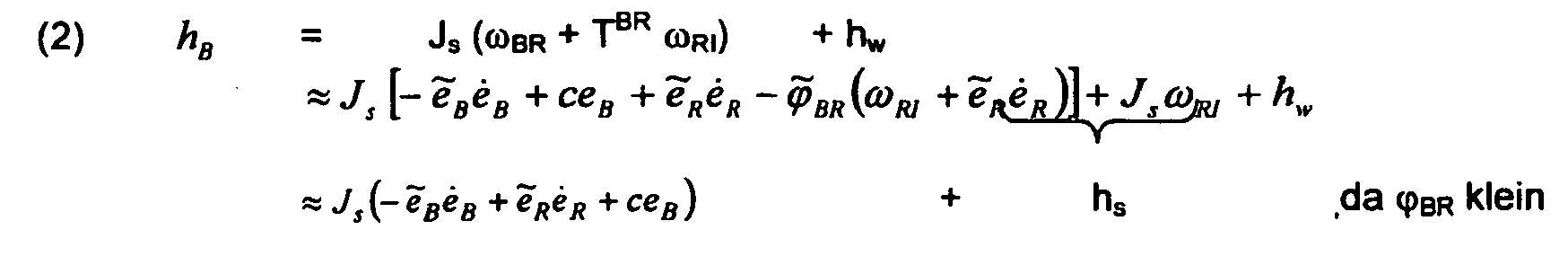
Da der Term Js (ωRI + ẽRėR ) durch die Wahl des Raddralls klein gegenüber hw bleibt, ist der Term Js ϕ̃ BR (ω RI + ẽRėR ) von zweiter Ordnung klein, womit hB praktisch unabhängig von ϕBR und somit TBR wird.
Außer der Bestimmung von hB über c gemäß Gleichung (2), (4) bietet sich alternativ die Verwendung eines Beobachters oder Kalmanfilters an, dass als Messgröße den um den Term mit den unbekannten c reduzierten Vektor hB benützt. die Gleichungen dafür lauten:
- z:
- Schätzvektor für hB
- K:
- Verstärkungsmatrix, z. B. "Kalman"-Verstärkung
Es liegen damit Lage- und Geschwindigkeitsabweichungen gegenüber dem Referenzsystem vor, womit das Raumfahrzeug in bekannter Weise durch Aufschaltung dieser beiden Anteile auf die Aktuatoren bezüglich des Referenzsystems ausgerichtet werden kann.
Zur Erläuterung des praktischen Vorgehens sei ein erdorientiertes Raumfahrzeug auf einer Kreisbahn betrachtet. Für den Orbitdrall h0 gilt hier die einfache Beziehung

- Rotational speed between body-fixed and reference coordinate system
- e B = T BR e R :
- Unit vector (EV) of the direction measurement in the body-fixed system (ie direction vector, obtained from direction vector measurement)
- e R :
- associated EV in the reference coordinate system with the additional property that the corresponding direction in the inertial system is time-variable (ie reference direction vector obtained from reference direction vector measurement)
- T BR = I - φ BR :
- to be determined transformation matrix small deviations between body-fixed and reference coordinate system, also corresponds to the representation of the deviation of the total spin from the reference total spin
- φ BR :
- Vector of small angles describing the deviation between body-fixed and reference system
- "~":
- Cross product operation
- c = e B T ω BR :
- rotational speed component to be determined in the direction of e B , hereinafter referred to as "longitudinal rate"
- Spin vector in the body-fixed coordinate system
- J s:
- Inertia momentum matrix of spacecraft
- ω RI :
- Rotation speed of the reference system compared to the inertial system
- hw:
- swirl content stored in the swirl wheels (= wheel spin)
- T R0 :
- Transformation matrix between reference and orbit system; It describes the desired position of the spacecraft and is usually given by bias values, which can also be time-varying.
- h 0 :
- as assumed assumed spin of the spacecraft in the orbit system
- e 0 :
- Measuring direction in the orbit system, known from orbit data
Since the term J s (ω RI + ẽ R ė R ) remains small compared to h w by the choice of the wheel spin, the term J s φ BR (ω RI + ẽ R ė R ) of second order is small, so that h B is practical is independent of φ BR and thus T BR .
In addition to the determination of h B over c according to Equation (2), (4), alternatively, the use of an observer or Kalman filter suggests that Measure using the vector h B reduced by the term with the unknown c. the equations are:- z:
- Estimation vector for h B
- K:
- Gain matrix, e.g. B. "Kalman" reinforcement
There are thus position and speed deviations with respect to the reference system, with which the spacecraft can be aligned in a known manner by connecting these two shares to the actuators with respect to the reference system.
To explain the practical procedure, consider an earth-oriented spacecraft on a circular path. For the orbit twist h 0 , the simple relationship applies here
Wie eingangs bereits erwähnt, bieten sich zwei Vorgehensweisen zur Ermittlung von h0(t) an:
- a) Propagation gemäß Gleichung (5): Hierzu ist abschnittsweise optische 3-Achsen Referenz, z. B. aus einem Sonnensensor nötig, um die unbekannten Anteile in ts (0) (z. B. Solarstörmomente) während dieser Phasen zu schätzen und h0 am Ende dieser Phasen auf einen Anfangswert zu initialisieren
- b) Nachführen eines Referenzmodells für h0: Hierfür wird zusätzlich berechnet
- h03 = eB T hB :
- da e0 = e3 bei Erdreferenz
- ĥoi
- Schätzung für h0i
- Ki:
- Aufschaltwerte, z.B. K1 = 3w0, K3 = 4 |w0|
- t̂i :
- Schätzwerte für tsi (0)
- a) Propagation according to equation (5): For this purpose, in sections optical 3-axis reference, z. For example, a sun sensor may be needed to estimate the unknown portions in t s (0) (eg, solar disturbances) during these phases, and initialize h 0 to an initial value at the end of these phases
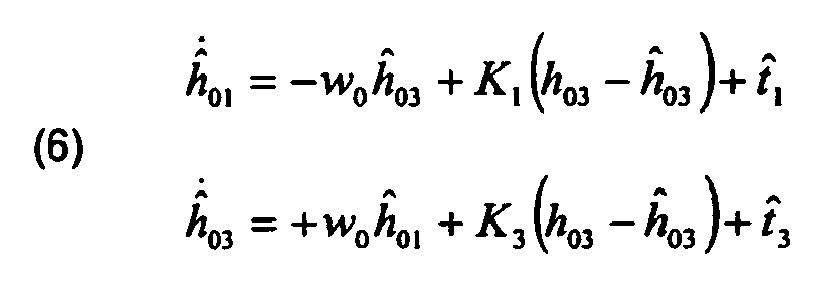
- b) Tracking a reference model for h 0 : This is calculated additionally
- h 03 = e B T h B :
- since e 0 = e 3 at earth reference
- ĥ oi
- Estimate for h 0i
- Ki:
- Switch-on values, eg K 1 = 3w 0 , K 3 = 4 | w 0 |
- t i :
- Estimates for t si (0)
Gleichung (6) sichert, dass für tsi (0) = t̂i die Schätzungen ĥ 0i gegen ĥ 0i konvergieren; für die angegebenen Werte von Ki ist dies nach einem Orbit der Fall. Die fehlende 2. Komponente von ĥ 0 wird berechnet gemäß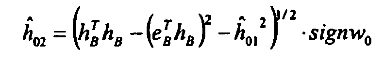
Der wesentliche Vorteil des beschriebenen Verfahrens liegt darin, dass unabhängig von der auch zeitvarianten Sollorientierung gegenüber dem Orbitsystem (z. B. beim sogenannten Yaw-Steering) alle Rechenschritte unverändert bleiben, da nur die Matrix TR0 entsprechend gewählt wird. Bei den eingangs erwähnten Verfahren sind dafür umfangreiche Rechnungen für Kompensationsterme oder sogar eine zeitvariable Dynamik für den Beobachter in Kauf zunehmen. Weiterhin können verschiedenartige Sensoren (z. B. Erdsensor, Magnetometer) als Messgeber verwendet werden.The essential advantage of the described method is that, irrespective of the time-variant desired orientation with respect to the orbit system (for example in so-called yaw steering), all computation steps remain unchanged since only the matrix T R0 is selected accordingly. In the case of the methods mentioned at the outset, extensive calculations for compensation terms or even time-variable dynamics for the observer are accepted. Furthermore you can Various types of sensors (eg earth sensor, magnetometer) can be used as sensors.
Durch diese Vorteile wird ein Einsatz des Verfahrens in allen Klassen von Raumfahrzeugen (LEO, MEO, GEO) möglich.These advantages make it possible to use the method in all classes of spacecraft (LEO, MEO, GEO).
Fig. 1 zeigt nun als ein spezielles Ausführungsbeispiel ein Blockschaltbild von Komponenten, die zur Realisierung des hier beschriebenen Verfahrens verwendet werden können:1 shows as a specific embodiment a block diagram of components that can be used to implement the method described here:
Aus einer bekannten Bahnposition des Raumfahrzeuges (beispielsweise durch zeitliche Propagation von Anfangswerten für Position und zeitliche Positionsänderung des Raumfahrzeugs, idealerweise unter Berücksichtigung externer Störungen, durch Nachführen eines Bahnmodells oder durch Raumfahrzeug-interne oder externe Positionsmessungen wie GPS), die mit Hilfe einer Bahnpositions-Einrichtung 11 ermittelt wird, wird mit Hilfe eines gespeicherten Orbitmodells in einer ersten Orbitmodell-Einrichtung 1 der Referenz-Einheitsvektor e o ermittelt und einer Einrichtung zur Längsratenbestimmung 2 zur Bestimmung von c gemäß Gleichung (4), zugeführt. Dieser Einrichtung 2 werden jedoch auch der mittels der bekannten, gespeicherten Transformationsmatrix T RO durch eine Transformations-Einrichtung 3, ins Referenzsystem transformierte Einheitsvektor e R , sowie dessen zeitliche Ableitung, gewonnen über den Differenzierer 4, zugeführt. Der Einheitsvektor e R wird ferner in das Modul zur Drallbestimmung 5, sowie in das Modul zur Lagebestimmung 6, eingespeist.From a known orbital location of the spacecraft (for example, by temporally propagating spacecraft initial and temporal position change ideals, ideally taking into account external disturbances, tracking a orbit model, or spacecraft internal or external position measurements, such as GPS) using a
Mit Hilfe eines in Fig. 1 dargestellten Sensors 9 (z. B. Erdsensor, Magnetometer) wird der Einheitsvektor e B bestimmt und den Modulen zur Längsratenbestimmung 2, zur Drallbestimmung 5, sowie zur Lagebestimmung 6, zugeführt. Den beiden erstgenannten Modulen wird ferner die über einen Differenzierer 7, gewonnene zeitliche Ableitung von e B zugeführt.1, the unit vector e B is determined and fed to the modules for
Aus Messsignalen einer Messeinrichtung 10 von Drallrädern, in Fig. 1 aus Gründen der Einfachheit nicht dargestellt, wird der Drallvektor der Räder, h w , gewonnen. Dieser wird in die Module zur Längsratenbestimmung 2, sowie zur Drallbestimmung 5, eingespeist. Die in Modul 2 ermittelte Längsrate c wird dem Modul zur Drallbestimmung 5, zugeführt, dessen Ergebnis, h B , wiederum in das Modul zur Lagebestimmung 6, sowie in ein Referenzmodell-Modul für den Orbitdrall 8, eingespeist wird. Diesem Referenzmodell-Modul 8 werden außerdem Schätzwerte i für externe Störmomente zugeführt.From measurement signals of a measuring
Der Ergebnisvektor des Referenzmodell-Moduls 8, ĥ 0, wird in das Längsratenbestimmungsmodul 2, zurückgeführt sowie über das in Fig. 1 unten aus Gründen der Anschaulichkeit nochmals dargestellte Modul 3 ins Referenzsystem transformiert und es wird das Ergebnis, nämlich der Gesamtdrallvektor h R im Referenz-Koordinatensystem, in das Modul zur Lagebestimmung 6 eingespeist. Dieses Modul 6 schließlich ermittelt entsprechend dem o.g. Verfahren aus den zwei ihm zugeführten Vektorpaaren e B , e R , h B , h R die die Satellitenlage beschreibende Transformationsmatrix T BR . Diese Transformationsmatrix beschreibt die Transformation zwischen körperfestem Koordinatensystem und Referenz-Koordinatensystem. Ebenso beschreibt diese Transformationsmatrix die Abweichung des Gesamtdralls von dem Referenz-Gesamtdrall.The result vector of the
Claims (7)
- A method for attitude determination of a spacecraft based on determining direction vectors and angular momentum vectors, sensor data and angular momentum data being determined as starting quantities for the attitude determination, wherein
a measurement of a direction vector (e B ) in a body frame coordinate system is carried out as a first vector determination with the aid of a sensor,
the determination of a reference direction vector (e R ) in a reference coordinate system is carried out as a second vector determination on the basis of the orbital position of the spacecraft and an orbit model,
the total angular momentum vector (h B ) of the spacecraft in the body frame coordinate system is determined as a third vector determination, characterised in that
the reference total angular momentum vector (h R ) of the spacecraft in a reference coordinate system is determined as a fourth vector determination by temporally propagating known initial values of the total angular momentum of the spacecraft or by temporally tracking a reference model for the total angular momentum, and
a determination of the attitude of the spacecraft is carried out on the basis of the four vectors (e B , eR, h B , h R ). - A method according to Claim 1,
characterised in that
the longitudinal rate component (c) of the angular velocity (ωBR) in the direction of the direction vector (e B ) between the body frame coordinate system
and the reference coordinate system is initially determined at least from the direction vector (e B ), the reference direction vector (e R ) and a total angular momentum (ĥ0) temporally propagated from known initial values or temporally tracked by means of a reference model,
the total angular momentum vector (he) in the body frame coordinate system is determined with the aid of the longitudinal rate component (c),
and a transformation matrix TBR, which describes the deviations of the actual attitude of the body frame coordinate system of the spacecraft from the reference coordinate system representing the setpoint attitude of the body frame coordinate system, is determined on the basis of the direction vector (e B ), the reference direction vector (e R ), the total angular momentum vector (h B ) and the reference total angular momentum vector (h R ). - A method according to Claim 2, characterised in that at least the direction vector (eB ) and the reference direction vector (eR ) are additionally used for determining the total angular momentum vector (h B ).
- A method according to Claim 2 or 3, characterised in that the determination of the longitudinal rate component (c) and the determination of the total angular momentum vector (h B ) are additionally carried out on the basis of the measured or estimated angular momentum vector (h w ) of momentum wheels of the spacecraft.
- An arrangement for attitude determination of a spacecraft, comprising the following components:an instrument (9) for measuring a direction
vector (eB) in a body frame coordinate system,an instrument (11) for determining the orbital position of the spacecraft,an arrangement (1, 3) for determining a reference direction vector (eR) in a reference coordinate system on the basis of the orbital position of the spacecraft and an orbit model,an instrument (5) for determining a total angular momentum vector (hB) in the body frame coordinate system,an arrangement (8, 3) for determining a reference total angular momentum vector (hR) in the reference coordinate system, characterised in that the reference total angular momentum vector (hR) is determined by temporally propagating known initial values of the total angular momentum of the spacecraft or by temporally tracking a reference model for the total angular momentum, andan instrument (6) for determining the attitude of the spacecraft on the basis of the four vectors (eB, eR, hB, hR). - An arrangement according to Claim 5, additionally comprising an instrument (2) for determining the longitudinal rate component (c) of the angular velocity (ωBR) in the direction of the direction vector (eB) between the body frame coordinate system and the reference coordinate system.
- An arrangement according to Claim 5 or 6, additionally comprising an instrument (10) for measuring or estimating the angular momentum vector (h w ) of momentum wheels of the spacecraft.
Applications Claiming Priority (2)
| Application Number | Priority Date | Filing Date | Title |
|---|---|---|---|
| DE10342866A DE10342866A1 (en) | 2003-09-15 | 2003-09-15 | Method for determining the position of a spacecraft with the aid of a direction vector and a total twist measurement |
| DE10342866 | 2003-09-15 |
Publications (2)
| Publication Number | Publication Date |
|---|---|
| EP1514799A1 EP1514799A1 (en) | 2005-03-16 |
| EP1514799B1 true EP1514799B1 (en) | 2007-01-24 |
Family
ID=34129819
Family Applications (1)
| Application Number | Title | Priority Date | Filing Date |
|---|---|---|---|
| EP04020693A Expired - Lifetime EP1514799B1 (en) | 2003-09-15 | 2004-09-01 | Method for attitude determination of spacecraft using a direction vector and a total momentum measurement |
Country Status (3)
| Country | Link |
|---|---|
| US (2) | US7797085B2 (en) |
| EP (1) | EP1514799B1 (en) |
| DE (2) | DE10342866A1 (en) |
Cited By (1)
| Publication number | Priority date | Publication date | Assignee | Title |
|---|---|---|---|---|
| CN110675718A (en) * | 2019-09-29 | 2020-01-10 | 南京理工大学 | Ground education satellite kit that can realize standard CubeSat function and its demonstration method |
Families Citing this family (8)
| Publication number | Priority date | Publication date | Assignee | Title |
|---|---|---|---|---|
| DE102009059694B3 (en) * | 2009-12-18 | 2011-03-17 | Astrium Gmbh | Method for determining position of spacecraft by multiple transmitters, involves measuring three orthogonal components of electromagnetic radiation fields on spacecraft |
| CN101858969A (en) * | 2010-03-26 | 2010-10-13 | 航天东方红卫星有限公司 | A Predetermination Method of Satellite Target Attitude Based on Optimal Virtual Rotation |
| CN102322862B (en) * | 2011-06-29 | 2013-07-24 | 航天东方红卫星有限公司 | Method for determining absolute orbit and relative orbit of formation flight satellite |
| CN103600853B (en) * | 2013-11-25 | 2016-04-27 | 北京卫星环境工程研究所 | For the method that magnetic moment of spacecraft compensates |
| CN104296751B (en) * | 2014-10-23 | 2017-05-10 | 航天东方红卫星有限公司 | Layout design method of multi-star sensor configuration layout |
| CN113984069B (en) * | 2021-04-30 | 2023-06-06 | 北京临近空间飞行器系统工程研究所 | Satellite light positioning navigation method based on artificial satellite |
| CN113358024B (en) * | 2021-05-08 | 2022-08-12 | 上海卫星工程研究所 | Satellite instrument relative precision measurement data processing method and system |
| CN115327925B (en) * | 2022-09-09 | 2023-12-15 | 北京理工大学 | Combined body posture finite time control method based on extended state observer |
Family Cites Families (30)
| Publication number | Priority date | Publication date | Assignee | Title |
|---|---|---|---|---|
| US3866025A (en) * | 1972-03-17 | 1975-02-11 | Rca Corp | Spacecraft attitude control system |
| DE2749868C3 (en) * | 1977-11-08 | 1980-05-22 | Messerschmitt-Boelkow-Blohm Gmbh, 8000 Muenchen | Sun and earth detection methods for satellites |
| DE3128054C2 (en) * | 1981-07-16 | 1983-05-26 | Messerschmitt-Bölkow-Blohm GmbH, 8000 München | "Device for the roll / yaw control of a satellite" |
| US4752884A (en) * | 1985-07-18 | 1988-06-21 | Hughes Aircraft Company | Precision platform pointing controller for a dual-spin spacecraft |
| US4725024A (en) * | 1985-11-15 | 1988-02-16 | Ford Aerospace & Communications Corporation | Method for spinning up a three-axis controlled spacecraft |
| US4757964A (en) * | 1986-07-17 | 1988-07-19 | Hughes Aircraft Company | Method for controlling the attitude of a spinning body in orbit |
| US5042752A (en) * | 1987-09-16 | 1991-08-27 | Messerschmitt-Bolkow-Blohm Gmbh | Apparatus for controlling the attitude of and stabilizing an elastic body |
| US5020744A (en) * | 1990-01-12 | 1991-06-04 | General Electric Company | Method for acquiring three-axis earth pointing attitude for an initially spinning spacecraft |
| US5080307A (en) * | 1990-05-14 | 1992-01-14 | Hughes Aircraft Company | Spacecraft earth-pointing attitude acquisition method |
| US5058835A (en) * | 1990-06-11 | 1991-10-22 | General Electric Company | Wheel speed management control system for spacecraft |
| FR2670746B1 (en) * | 1990-12-21 | 1993-04-16 | Aerospatiale | ATTITUDE MONITORING SYSTEM FOR 3-AXIS SATELLITE ,; IN PARTICULAR FOR OBSERVATION SATELLITE. |
| US5222023A (en) * | 1991-04-02 | 1993-06-22 | Space Systems/Loral, Inc. | Compensated transition for spacecraft attitude control |
| DE4129627C2 (en) * | 1991-09-06 | 1994-08-04 | Deutsche Aerospace | Device and method for position control of a spacecraft to be rotated about a body-fixed axis |
| US5255879A (en) * | 1991-11-27 | 1993-10-26 | Hughes Aircraft Company | Three axes stabilized spacecraft and method of sun acquisition |
| FR2699701B1 (en) | 1992-12-17 | 1995-03-24 | Aerospatiale | Method of controlling the attitude of a satellite pointed towards a celestial object and satellite adapted to its implementation. |
| US5452869A (en) * | 1992-12-18 | 1995-09-26 | Hughes Aircraft Company | On-board three-axes attitude determination and control system |
| DE69606275T2 (en) * | 1995-08-11 | 2000-07-13 | Daimlerchrysler Ag | Method for position control of a three-axis stabilized, earth-oriented moment of inertia stabilized spacecraft |
| DE59608372D1 (en) * | 1995-08-11 | 2002-01-17 | Astrium Gmbh | Device for position control and stabilization of a spacecraft |
| EP0790542B1 (en) | 1995-08-11 | 2000-01-19 | DaimlerChrysler AG | Method for controlling the attitude of a three-axis stabilized, earth oriented bias momentum spacecraft |
| US5791598A (en) * | 1996-01-16 | 1998-08-11 | Globalstar L.P. and Daimler-Benz Aerospace AG | Dynamic bias for orbital yaw steering |
| US5826828A (en) * | 1996-02-05 | 1998-10-27 | Hughes Electronics Corporation | Sun/earth acquisition without thrusters |
| US6000661A (en) * | 1996-10-16 | 1999-12-14 | Space Systems/Loral, Inc. | Autonomous spacecraft payload base motion estimation and correction |
| US6282467B1 (en) * | 1997-10-14 | 2001-08-28 | The Boeing Company | Three-axis inertial attitude determination for spinning spacecraft |
| US6019320A (en) * | 1998-09-15 | 2000-02-01 | Hughes Electronics Corporation | Spacecraft acquisition of sun pointing |
| US6311932B1 (en) * | 1999-11-30 | 2001-11-06 | Space Systems/Loral Inc. | Yaw steering momentum system |
| US6347262B1 (en) * | 2000-01-05 | 2002-02-12 | Hughes Electronics Corporation | Minimum fuel attitude and nutation controller for spinning spacecraft |
| GB2360099B (en) * | 2000-03-07 | 2004-02-11 | Matra Marconi Space | Attitude control system for a spacecraft |
| AU2002251827A1 (en) * | 2001-01-26 | 2002-08-06 | The Charles Stark Draper Laboratory, Inc. | Miniature attitude sensing suite |
| FR2821683B1 (en) * | 2001-03-01 | 2003-06-13 | Agence Spatiale Europeenne | ORDERING METHOD FOR CONTROLLING OR STABILIZING THE ORIENTATION OF A MACHINE IN SPACE |
| EP1783050B1 (en) * | 2004-06-22 | 2009-05-06 | Japan Aerospace Exploration Agency | Ultrahigh altitude sun synchronous orbit satellite system |
-
2003
- 2003-09-15 DE DE10342866A patent/DE10342866A1/en not_active Ceased
-
2004
- 2004-09-01 EP EP04020693A patent/EP1514799B1/en not_active Expired - Lifetime
- 2004-09-01 DE DE502004002746T patent/DE502004002746D1/en not_active Expired - Lifetime
- 2004-09-14 US US10/939,994 patent/US7797085B2/en not_active Expired - Fee Related
-
2010
- 2010-08-09 US US12/852,603 patent/US7996119B2/en not_active Expired - Fee Related
Cited By (2)
| Publication number | Priority date | Publication date | Assignee | Title |
|---|---|---|---|---|
| CN110675718A (en) * | 2019-09-29 | 2020-01-10 | 南京理工大学 | Ground education satellite kit that can realize standard CubeSat function and its demonstration method |
| CN110675718B (en) * | 2019-09-29 | 2021-05-07 | 南京理工大学 | Ground education satellite kit that can realize standard CubeSat function and its demonstration method |
Also Published As
| Publication number | Publication date |
|---|---|
| DE502004002746D1 (en) | 2007-03-15 |
| US20050090948A1 (en) | 2005-04-28 |
| US7797085B2 (en) | 2010-09-14 |
| US7996119B2 (en) | 2011-08-09 |
| DE10342866A1 (en) | 2005-04-21 |
| EP1514799A1 (en) | 2005-03-16 |
| US20110022309A1 (en) | 2011-01-27 |
Similar Documents
| Publication | Publication Date | Title |
|---|---|---|
| EP0856784B1 (en) | Method and device for the on-board determination of a satellite s position | |
| EP0795806B1 (en) | Apparatus and method for attitude control and stabilisation of a spacecraft | |
| DE60120363T2 (en) | ORIENTATION DETERMINATION IN A TILTABLE BODY BY MEANS OF A MODIFIED QUATERNATION DATA PRESENTATION | |
| DE10219861B4 (en) | Method and device for long-term navigation | |
| EP0601032B1 (en) | Attitude control process and device for a spacecraft to be rotated around a body axis | |
| DE19950247A1 (en) | Regulation and procedure for Sstellites | |
| DE3436839A1 (en) | STEERING PROCESSOR | |
| DE10228639A1 (en) | Long term inertial navigation method for vehicle in which two inertial navigation units are used with resulting state vectors combined to yield instantaneous vector value | |
| EP0557591A1 (en) | Device for determining the relative orientation of a body | |
| EP1514799B1 (en) | Method for attitude determination of spacecraft using a direction vector and a total momentum measurement | |
| DE102004001319A1 (en) | System and method of a steer-by-wire control for vehicles by using a multiple decoupling control | |
| DE10312154B4 (en) | Method and apparatus for performing object tracking | |
| DE102004001320A1 (en) | System and method of a steer-by-wire control for vehicles with a reference angle generator for the front wheels | |
| DE102016114366B4 (en) | FAILSAFE REDUCED ORDER INERTIAL UNIT MEASURING SYSTEM | |
| DE2818202A1 (en) | NAVIGATION DEVICE FOR LAND, AIR OR SEA VEHICLES | |
| EP0748737B1 (en) | Three-axis-stabilized earth satellite and corresponding sun and earth acquisition manoeuvers | |
| DE69601853T2 (en) | Method and system for controlling the position or orientation of a spacecraft | |
| DE2922415C2 (en) | Navigation device for land vehicles | |
| DE69628785T2 (en) | Method and device for determining and correcting errors in magnetometer measurements | |
| DE3214373A1 (en) | METHOD AND DEVICE FOR THE POSITION CONTROL OF A SATELLITE | |
| DE19924908B4 (en) | Three-axis attitude determination method for a low-flying satellite | |
| EP0276663B1 (en) | Device for determining the time variant position and the errors of a repeater navigation system relative to a master system | |
| EP0179197A2 (en) | Arrangement for determining the time-variant position and the errors of a repeater navigation system relatively to a master system | |
| EP0700829B1 (en) | Method for determining the angular impulse vector of a satellite | |
| DE19636425C1 (en) | Navigation method using complementary measurement methods for motor vehicle |
Legal Events
| Date | Code | Title | Description |
|---|---|---|---|
| PUAI | Public reference made under article 153(3) epc to a published international application that has entered the european phase |
Free format text: ORIGINAL CODE: 0009012 |
|
| AK | Designated contracting states |
Kind code of ref document: A1 Designated state(s): AT BE BG CH CY CZ DE DK EE ES FI FR GB GR HU IE IT LI LU MC NL PL PT RO SE SI SK TR |
|
| AX | Request for extension of the european patent |
Extension state: AL HR LT LV MK |
|
| 17P | Request for examination filed |
Effective date: 20050316 |
|
| AKX | Designation fees paid |
Designated state(s): DE FR GB IT |
|
| GRAP | Despatch of communication of intention to grant a patent |
Free format text: ORIGINAL CODE: EPIDOSNIGR1 |
|
| RAP1 | Party data changed (applicant data changed or rights of an application transferred) |
Owner name: ASTRIUM GMBH |
|
| GRAS | Grant fee paid |
Free format text: ORIGINAL CODE: EPIDOSNIGR3 |
|
| GRAA | (expected) grant |
Free format text: ORIGINAL CODE: 0009210 |
|
| AK | Designated contracting states |
Kind code of ref document: B1 Designated state(s): DE FR GB IT |
|
| REG | Reference to a national code |
Ref country code: GB Ref legal event code: FG4D Free format text: NOT ENGLISH |
|
| REF | Corresponds to: |
Ref document number: 502004002746 Country of ref document: DE Date of ref document: 20070315 Kind code of ref document: P |
|
| GBT | Gb: translation of ep patent filed (gb section 77(6)(a)/1977) |
Effective date: 20070426 |
|
| ET | Fr: translation filed | ||
| PLBE | No opposition filed within time limit |
Free format text: ORIGINAL CODE: 0009261 |
|
| STAA | Information on the status of an ep patent application or granted ep patent |
Free format text: STATUS: NO OPPOSITION FILED WITHIN TIME LIMIT |
|
| 26N | No opposition filed |
Effective date: 20071025 |
|
| REG | Reference to a national code |
Ref country code: FR Ref legal event code: PLFP Year of fee payment: 13 |
|
| PGFP | Annual fee paid to national office [announced via postgrant information from national office to epo] |
Ref country code: DE Payment date: 20160921 Year of fee payment: 13 Ref country code: GB Payment date: 20160920 Year of fee payment: 13 |
|
| PGFP | Annual fee paid to national office [announced via postgrant information from national office to epo] |
Ref country code: FR Payment date: 20160921 Year of fee payment: 13 |
|
| PGFP | Annual fee paid to national office [announced via postgrant information from national office to epo] |
Ref country code: IT Payment date: 20160922 Year of fee payment: 13 |
|
| REG | Reference to a national code |
Ref country code: DE Ref legal event code: R119 Ref document number: 502004002746 Country of ref document: DE |
|
| GBPC | Gb: european patent ceased through non-payment of renewal fee |
Effective date: 20170901 |
|
| REG | Reference to a national code |
Ref country code: FR Ref legal event code: ST Effective date: 20180531 |
|
| PG25 | Lapsed in a contracting state [announced via postgrant information from national office to epo] |
Ref country code: GB Free format text: LAPSE BECAUSE OF NON-PAYMENT OF DUE FEES Effective date: 20170901 Ref country code: DE Free format text: LAPSE BECAUSE OF NON-PAYMENT OF DUE FEES Effective date: 20180404 |
|
| PG25 | Lapsed in a contracting state [announced via postgrant information from national office to epo] |
Ref country code: IT Free format text: LAPSE BECAUSE OF NON-PAYMENT OF DUE FEES Effective date: 20170901 Ref country code: FR Free format text: LAPSE BECAUSE OF NON-PAYMENT OF DUE FEES Effective date: 20171002 |