EP1514759A1 - Connected bogies - Google Patents
Connected bogies Download PDFInfo
- Publication number
- EP1514759A1 EP1514759A1 EP03730865A EP03730865A EP1514759A1 EP 1514759 A1 EP1514759 A1 EP 1514759A1 EP 03730865 A EP03730865 A EP 03730865A EP 03730865 A EP03730865 A EP 03730865A EP 1514759 A1 EP1514759 A1 EP 1514759A1
- Authority
- EP
- European Patent Office
- Prior art keywords
- cars
- truck
- wires
- connecting wire
- frame
- Prior art date
- Legal status (The legal status is an assumption and is not a legal conclusion. Google has not performed a legal analysis and makes no representation as to the accuracy of the status listed.)
- Granted
Links
Images



Classifications
-
- B—PERFORMING OPERATIONS; TRANSPORTING
- B61—RAILWAYS
- B61F—RAIL VEHICLE SUSPENSIONS, e.g. UNDERFRAMES, BOGIES OR ARRANGEMENTS OF WHEEL AXLES; RAIL VEHICLES FOR USE ON TRACKS OF DIFFERENT WIDTH; PREVENTING DERAILING OF RAIL VEHICLES; WHEEL GUARDS, OBSTRUCTION REMOVERS OR THE LIKE FOR RAIL VEHICLES
- B61F3/00—Types of bogies
- B61F3/12—Types of bogies specially modified for carrying adjacent vehicle bodies of articulated trains
- B61F3/125—Types of bogies specially modified for carrying adjacent vehicle bodies of articulated trains with more than one axle or wheel set
-
- B—PERFORMING OPERATIONS; TRANSPORTING
- B61—RAILWAYS
- B61G—COUPLINGS; DRAUGHT AND BUFFING APPLIANCES
- B61G5/00—Couplings for special purposes not otherwise provided for
- B61G5/06—Couplings for special purposes not otherwise provided for for, or combined with, couplings or connectors for fluid conduits or electric cables
- B61G5/10—Couplings for special purposes not otherwise provided for for, or combined with, couplings or connectors for fluid conduits or electric cables for electric cables
Definitions
- the present invention relates to an articulated truck mounted between two cars.
- a train is equipped with an articulated truck between two cars thereof in view of cost reduction, and improved running stability for comfortable ride-in, etc.
- the train (train set) is constituted by mounting an articulated truck 101 between a car 102 and a car 103
- the articulated truck 101 is positioned in a space under the cars.
- Wires 104 connecting the cars 102 and 103 cannot sag down under a restriction of a space because of the presence of the articulated truck 101.
- car body ends of the cars are recessed to form spaces (concave portions) 102a and 103a, and the wires 104 are provided between them above the articulated truck 101.
- the present invention has been developed under the circumstances, and an object of the present invention is to provide an articulated truck which allows wire connection and pipe connection between cars to be easily achieved.
- the invention according to Claim 1 is an articulated truck mounted between two cars, comprising a connecting wire or a connecting pipe configured to interconnect wires or pipes of two cars which are disposed under floors of the two cars; and a truck frame of the articulated truck, wherein the connecting wire or the connecting pipe is mounted to the truck frame.
- mounting to the truck frame means “mounted directly or indirectly to the truck frame.”
- the wires or the pipes of the two cars are connected to each other through the connecting wire or the connecting pipe mounted to the articulated truck.
- wire connection or pipe connection between two cars is easily achieved. Since it is not necessary to recess car body ends to form spaces (concave portions) unlike in the conventional construction, an effective space within a passenger's cabin is not reduced, and an area of a passage can be increased.
- the connecting wire or the connecting pipe configured to connect the wires or the pipes of the cars is mounted to the truck frame of the articulated truck, the structure of the car body does not become intricate. Further, since the center of gravity of the car body is substantially as high as that of the train which is not equipped with the truck, running stability is improved and car performance is advantageously improved.
- the connecting wire or the connecting pipe has connecting members at both end portions, and the connecting members are removably connected to receiving members provided at end portions of the wires or the pipes of the cars.
- connection or disconnection between the connecting wire or the connecting pipe of the articulated truck and the wires or the pipes of the cars can be carried out under the floors of the cars. Consequently, maintenance of the cars is facilitated.
- the truck frame may be provided with a concave portion on an upper portion of a side frame thereof, and an intermediate portion of the connecting wire or the connecting pipe may be mounted within the concave portion.
- the concave portion formed on the upper portion of the side frame of the truck frame of the articulated truck which has been conventionally a dead space, can be utilized to store the connecting wire or the connecting pipe configured to connect the wires or the pipes of the cars to each other.
- a cover plate is configured to cover the concave portion formed on the upper portion of the side frame of the truck frame, and both end portions of the connecting wire or the connecting pipe penetrate through the cover plate and extend to outside of the concave portion.
- a main portion other than the both end portions of the connecting wire or the connecting pipe configured to connect the wires or the pipes of the cars is stored in a space defined by the concave portion on the upper portion of the side frame and the cover plate and is not exposed to outside.
- the connecting wire or the connecting pipe is not necessarily stored within the truck frame.
- the connecting wire or the connecting pipe is mounted to the outer side portion of the truck frame by using the mounting device.
- the mounting device may have a protecting pipe member mounted to extend along the outer side portion of the truck frame, and a fixing member configured to mount and fix the protecting pipe member to the outer side portion of the truck frame, wherein the connecting wire or the connecting pipe extends within the protecting pipe member.
- the mounting device may have mounting members mounted to the connecting wire or the connecting pipe to be spaced a predetermined distance apart from each other, an attaching member attached to the truck frame or car bodies of the cars, and a flexible connecting member configured to connect the mounting members to the attaching member.
- the term "flexible connecting member” means a connecting member configured to connect the mounting members of the connecting wire or the connecting pipe to the attaching member such that the connecting wire or the connecting pipe is not mechanically or fixedly connected but is displaceable within a certain range in order to inhibit the connecting wire or the connecting pipe from being disengaged from the truck frame or the car bodies of the cars, and includes chains, belt, and strings, etc.
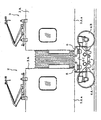
- Fig. 1 is a view for explaining a train to which a wire structure of an articulated truck, according to an embodiment of a wire and pipe structure of an articulated truck of the present invention is applied.
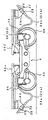
- Fig. 2 is a cross-sectional view taken in the direction of arrows along line A-A in Fig. 1.
- an articulated truck (two axle articulated truck) 4 provided with front wheels 4A and rear wheels 4B is mounted, for example, between a second car 2 and a third car 3.
- the articulated truck 4 allows car bodies 2A and 3A of the front and rear cars 2 and 3 to be supported from below by air springs 5 and 6.
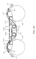
- wires (electric wires) disposed under the floors of car body frames 2Aa and 3Aa of the cars 2A and 3A are, as shown in Figs. 3 and 4A and 4B interconnected through connecting wires 21 (corresponding to the conventional crossovers) mounted to truck frames 4C of the truck 4.
- the connecting wires 21 are inserted into flexible protecting pipe members 28, and are mounted to the truck frames 4C in such a manner that intermediate portions thereof are provided within concave portion 4Da (see Fig. 4A) which are trapezoid-shaped in cross section and formed on upper portions of right and left side frames 4D of the truck frame 4C. That is, the connecting wires 21 are entirely housed within the protecting pipe members 28.
- the concave portions 4Da are closed such that their upper openings are covered with cover plates 37 which are thin-plate shaped.
- An intermediate portion of each protecting pipe member 28 (connecting wires 21) is mounted to extend along a bottom surface of the concave portion 4Da. Both end portions of the protecting pipe member 28 (connecting wires 21) penetrate through the cover plate 37 from an inside of the concave portion 4Da to an outside of the concave portion 4Da and further extend in the longitudinal direction of the truck 4 outside the concave portion 4Da to positions nearer the cars 2 and 3.
- Three lids 31A, 31B, and 31C are removably attached to the cover plate 37.
- the lids 31A and 31C serve to fix the protecting pipe member 28 (connecting wires 21) penetrating through the cover plate 37 to the cover plate 37.
- the protecting pipe member 28 is removably mounted and fixed to a portion of a bottom surface of the concave portion 3Da which corresponds to the lid 31B by means of a fixing member 32.
- the protecting pipe members 28 (connecting wires 21) penetrating through the cover plate 37 are bundled by bundle members 33 and 34 and mounted to front and rear upper portions of the side frame 4D.
- the protecting pipe members 28 (connecting wires 21) are fixedly mounted to front and rear end portions of the side frame 4D by means of mounting brackets 35 and 36.
- Connectors (connecting members) 22 and 23 are provided at front and rear end portions of the protecting pipe member 28 (connecting wires 21) to electrically connect the connecting wires 21 stored in the protecting pipe member 28 to wires of the cars.
- Mounting brackets 24 and 25 are mounted under the car body frames 2Aa and 3Aa of the cars 2A and 3A, respectively.
- the mounting brackets 24 and 25 serve to mount connectors (receiving members) 26 and 27 of wires 29 and 30 of the cars.
- the connectors 22 and 23 of the truck 4 are removably connected to the connectors (receiving members) 26 and 27 of the wires 29 and 30 of the cars, thus facilitating wire connection between the cars.
- the protecting pipe member 28 greatly sags down (sag portions 28a and 28b (21a and 21b)) in front of the wheel 4A and behind the wheel 4B and then are removably connected to the connectors 26 and 27 of the cars.
- the connectors 26 and 27 are low voltage couplers when the wires (electric wires) 29 and 30 are low-voltage crossovers such as control lines or signal lines, and are high-voltage connectors when the wires 29 and 30 are high-voltage crossovers.
- the connecting wires 21(crossovers) are stored within the concave portion 4Da which is an inner space within the side frame 4D of the truck frame 4C to connect the wires (electric wires) 29 and 30 of the front and rear cars 2 and 3 to each other, and the wires 29 and 30 of the first and second cars 2 and 3 are connected to each other through the connecting wires 21.
- the connecting wires 21 configured to connect the wires 29 and 30 of the cars can be easily disposed by efficiently utilizing a dead space within the truck frame 4C (concave portion 4Da of the side frame 4D).
- the connecting wires 21 mounted to the side frame 4D requires replacement, the connecting wires 21 can be easily replaced merely by detaching the three lids 31A, 31B, and 31C attached to the cover plate 37 and without detaching the cover plate 37.
- crossovers provided between coupled cars are configured to connect connecting portions provided at end portions of front and rear car bodies.
- the crossovers are made longer than an interval between the connecting portions to deal with movement of the cars associated with travel of the train, and are exposed and sag down on the rail side by their own weights.
- the inter-car wires are provided within the side frame 4D of the truck frame 4C by utilizing the inner space of the truck frame 4C of the articulated truck 4, the inter-car wires (connecting wires) are not exposed. Therefore, unlike in Japanese Utility Model Application Publication No. Hei. 6 - 37045, it is not necessary to provide the protecting plate for protecting the crossovers provided between the coupling portions of the railway cars under the crossovers in order to inhibit damage to the crossovers.
- connecting wires 21 which function as the crossovers provided between the front and rear coupled cars are mounted within the concave portion 4Da of the side frame 4D of the truck frame 4C, they may alternatively be mounted to the outer surface of the truck frame 4C as will be described in a second embodiment.
- Fig. 5A is a side view of a construction in which a protecting pipe member (connecting wires) is directly fixed to the side frame according to a second embodiment of the present invention.
- Fig. 5B is a cross-sectional view taken along line B-B in Fig. 5A.
- a flexible protecting pipe member 43 which is bent to sag down, is mounted and fixed to an outer surface of a side frame 42A forming a truck frame 42 of an articulated truck 41 by a plurality of mounting members 44.
- Connecting wires 45 are inserted into the protecting pipe member 43 to connect wires (feeder wires) under the floors of the front and rear cars to each other. Since the connecting wires 45 are inserted into the protecting pipe member 43, the connecting wires 45 and the protecting pipe member 43 are positioned. In other words, the protecting pipe member 43 allows the connecting wires 45 to be fixed to the truck frame 42.
- an inner diameter of the protecting member 43 may be suitably changed according to the diameter of the inserted wires (electric wires), the number of wires, etc, and the position at which the protecting pipe member 43 is mounted and fixed may be suitably changed as desired.
- the protecting pipe member 43 (connecting wires 45) is mounted and fixed to the truck frame 42 (side frame 42A) at positions more distant from the articulated truck 41 by mounting members 46 and 47.
- the protecting pipe member 43 (connecting wires 45) is mounted to an outer surface of the truck frame 42, it is not necessary to entirely fix the protecting pipe member 43. Instead, the protecting pipe member 43 may be mounted to be movable within a predetermined range as shown in Figs. 6A and 6B.
- mounting rings 51 are mounted to the protecting pipe member 43 to be spaced apart a predetermined distance from each other in an axial direction of the protecting pipe member 43, and attaching members 54 are provided on the truck frame 42 or on the front and rear car bodies 52 and 53 so as to correspond to the mounting rings 51. And, the mounting rings 51 are connected to the attaching members 54 through connecting chains (flexible connecting members) 55. In this case, the mounting rings 51 are movable with respect to the attaching members 54 within a range, and within that range, mounting portions of the protecting pipe member 43 (mounting portions of the mounting rings 51) are displaceable.
- the present invention is practiced as described above. Since the wires and the pipes disposed under the floor of car body frames are connected to each other through the connecting wires or the connecting pipe mounted to the truck frame of the articulated truck, wiring and piping become easy and maintenance of the articulated truck is facilitated.
- the connecting wires or the connecting pipes may be each structured to have connecting members at both ends portions and receiving members provided at end portions of the wires or the pipes of the cars are connected to the connecting members.
Landscapes
- Engineering & Computer Science (AREA)
- Mechanical Engineering (AREA)
- Body Structure For Vehicles (AREA)
- Electric Cable Arrangement Between Relatively Moving Parts (AREA)
- Earth Drilling (AREA)
- Handcart (AREA)
- Noodles (AREA)
- Details Of Indoor Wiring (AREA)
- Ultra Sonic Daignosis Equipment (AREA)
- Control Of Motors That Do Not Use Commutators (AREA)
- Transmission And Conversion Of Sensor Element Output (AREA)
Abstract
Description
Claims (12)
- An articulated truck mounted between two cars, comprising;whereina connecting wire or a connecting pipe configured to interconnect wires or pipes of two cars which are disposed under floors of the two cars; anda truck frame of the articulated truck,
the connecting wire or the connecting pipe is mounted to the truck frame. - The articulated truck according to Claim 1, wherein the connecting wire or the connecting wire has connecting members at both end portions, and
the connecting members are removably connected to receiving members provided at end portions of the wires or the pipes of the cars. - The articulated truck according to Claim 1, wherein the truck frame is provided with a concave portion on an upper portion of a side frame thereof, and an intermediate portion of the connecting wire or the connecting pipe is mounted within the concave portion.
- The articulated truck according to Claim 2, wherein the truck frame is provided with a concave portion on an upper portion of a side frame thereof, and an intermediate portion of the connecting wire or the connecting pipe is mounted within the concave portion.
- The articulated truck according to Claim 3, further comprising:wherein both end portions of the connecting wire or the connecting pipe penetrate through the cover plate and extend to outside of the concave portion.a cover plate configured to cover the connecting wire or the connecting pipe within the concave portion,
- The articulated truck according to Claim 4, further comprising:wherein both end portions of the connecting wire or the connecting pipe penetrate through the cover plate and extend to outside of the concave portion.a cover plate configured to cover the connecting wire or the connecting pipe within the concave portion,
- The articulated truck according to Claim 1, further comprising:a mounting device configured to mount the connecting wire or the connecting pipe to an outer side portion of the truck frame.
- The articulated truck according to Claim 2, further comprising:a mounting device configured to mount the connecting wire or the connecting pipe to an outer side portion of the truck frame.
- The articulated truck according to Claim 7, wherein
the mounting device has a protecting pipe member mounted to extend along the outer side portion of the truck frame, and a fixing member configured to mount and fix the protecting pipe member to the outer side portion of the truck frame,
wherein the connecting wire or the connecting pipe extends within the protecting pipe member. - The articulated truck according to Claim 8, wherein
the mounting device has a protecting pipe member mounted to extend along the outer side portion of the truck frame, and a fixing member configured to mount and fix the protecting pipe member to the outer side portion of the truck frame,
wherein the connecting wire or the connecting pipe extends within the protecting pipe member. - The articulated truck according to Claim 7, wherein the mounting device has mounting members mounted to the connecting wire or the connecting pipe to be spaced a predetermined distance apart from each other, an attaching member attached to the truck frame or car bodies of the cars, and a flexible connecting member configured to connect the mounting members to the attaching member.
- The articulated truck according to Claim 8, wherein the mounting device has mounting members mounted to the connecting wire or the connecting pipe to be spaced a predetermined distance apart from each other, an attaching member attached to the truck frame or car bodies of the cars, and a flexible connecting member configured to connect the mounting members to the attaching member.
Applications Claiming Priority (5)
| Application Number | Priority Date | Filing Date | Title |
|---|---|---|---|
| JP2002172460 | 2002-06-13 | ||
| JP2002172460 | 2002-06-13 | ||
| JP2002365065 | 2002-12-17 | ||
| JP2002365065A JP3844732B2 (en) | 2002-06-13 | 2002-12-17 | Wiring and piping structure for articulated cart |
| PCT/JP2003/007307 WO2003106239A1 (en) | 2002-06-13 | 2003-06-10 | Connected bogies |
Publications (3)
| Publication Number | Publication Date |
|---|---|
| EP1514759A1 true EP1514759A1 (en) | 2005-03-16 |
| EP1514759A4 EP1514759A4 (en) | 2007-11-07 |
| EP1514759B1 EP1514759B1 (en) | 2011-03-16 |
Family
ID=29738384
Family Applications (1)
| Application Number | Title | Priority Date | Filing Date |
|---|---|---|---|
| EP03730865A Expired - Lifetime EP1514759B1 (en) | 2002-06-13 | 2003-06-10 | Connected bogies |
Country Status (8)
| Country | Link |
|---|---|
| US (1) | US7267058B2 (en) |
| EP (1) | EP1514759B1 (en) |
| JP (1) | JP3844732B2 (en) |
| AT (1) | ATE501916T1 (en) |
| AU (1) | AU2003242128A1 (en) |
| CA (1) | CA2486755C (en) |
| DE (1) | DE60336395D1 (en) |
| WO (1) | WO2003106239A1 (en) |
Cited By (4)
| Publication number | Priority date | Publication date | Assignee | Title |
|---|---|---|---|---|
| DE202011051250U1 (en) * | 2011-09-09 | 2012-12-10 | Weidmüller Interface GmbH & Co. KG | Electrical connection unit |
| EP3339131A1 (en) * | 2016-12-22 | 2018-06-27 | Bombardier Transportation GmbH | Train set with at least one suspension device |
| CN106428085B (en) * | 2016-09-30 | 2018-08-24 | 中车南京浦镇车辆有限公司 | A kind of anti-breaking cable support of bogie high intensity |
| EP4335716A1 (en) * | 2022-09-09 | 2024-03-13 | Siemens Mobility GmbH | Railway vehicle |
Families Citing this family (12)
| Publication number | Priority date | Publication date | Assignee | Title |
|---|---|---|---|---|
| US7025774B2 (en) | 2001-06-12 | 2006-04-11 | Pelikan Technologies, Inc. | Tissue penetration device |
| EP2374685B1 (en) * | 2010-04-12 | 2013-01-23 | Tyco Electronics France SAS | Connecting arrangement for connecting supply lines of railway vehicles |
| WO2013057794A1 (en) | 2011-10-18 | 2013-04-25 | 三菱電機株式会社 | Jumper connector |
| CN102490746A (en) * | 2012-01-05 | 2012-06-13 | 南车株洲电力机车有限公司 | Light rail vehicle and non-power bogie thereof |
| DE102014218944A1 (en) | 2014-09-19 | 2016-03-24 | Leoni Kabel Holding Gmbh | Wagon crossing system for guiding at least one supply cable and clamping part for such a car transition system |
| CN104325991A (en) * | 2014-11-13 | 2015-02-04 | 南车株洲电力机车有限公司 | Rail vehicle and hinged bogie for same |
| CN106428084A (en) * | 2017-01-05 | 2017-02-22 | 中车南京浦镇车辆有限公司 | Anti-fatigue anti-breaking axle end cable rack for bogie |
| CN107380177B (en) * | 2017-06-08 | 2019-03-22 | 中车青岛四方机车车辆股份有限公司 | Vehicle cable integrated structure, bogie and vehicle |
| CN108238059A (en) * | 2018-02-26 | 2018-07-03 | 沈阳新阳光机电科技有限公司 | Rack railway coach |
| JP7184734B2 (en) * | 2019-11-27 | 2022-12-06 | 株式会社日立製作所 | rail vehicle |
| FR3141425A1 (en) * | 2022-10-31 | 2024-05-03 | Alstom Holdings | Intercirculation box for the end of a railway vehicle car and associated assembly method |
| CN118907171B (en) * | 2024-09-30 | 2025-11-07 | 中车青岛四方机车车辆股份有限公司 | Coupler wiring structure for railway vehicle and locomotive of railway vehicle |
Family Cites Families (6)
| Publication number | Priority date | Publication date | Assignee | Title |
|---|---|---|---|---|
| US1661659A (en) | 1926-02-01 | 1928-03-06 | Gray Percy | Water storage tank |
| US1681659A (en) * | 1927-06-28 | 1928-08-21 | Alfred T Clark | Air-pipe connection for articulated cars |
| US2036535A (en) | 1933-02-21 | 1936-04-07 | Charles A Nelson | Method of and apparatus for transporting goods |
| JPS59102564U (en) | 1982-12-27 | 1984-07-10 | 株式会社東芝 | railway vehicle bogie |
| JPH0637045U (en) | 1992-10-20 | 1994-05-17 | 日本車輌製造株式会社 | Railroad crossover protection device |
| US5601030A (en) * | 1996-03-04 | 1997-02-11 | Brouillette; Michael F. | Railraod bogie, for connecting vehicles in an articulated train |
-
2002
- 2002-12-17 JP JP2002365065A patent/JP3844732B2/en not_active Expired - Fee Related
-
2003
- 2003-06-10 AT AT03730865T patent/ATE501916T1/en not_active IP Right Cessation
- 2003-06-10 WO PCT/JP2003/007307 patent/WO2003106239A1/en not_active Ceased
- 2003-06-10 AU AU2003242128A patent/AU2003242128A1/en not_active Abandoned
- 2003-06-10 CA CA002486755A patent/CA2486755C/en not_active Expired - Fee Related
- 2003-06-10 DE DE60336395T patent/DE60336395D1/en not_active Expired - Lifetime
- 2003-06-10 EP EP03730865A patent/EP1514759B1/en not_active Expired - Lifetime
- 2003-06-10 US US10/517,016 patent/US7267058B2/en not_active Expired - Fee Related
Cited By (4)
| Publication number | Priority date | Publication date | Assignee | Title |
|---|---|---|---|---|
| DE202011051250U1 (en) * | 2011-09-09 | 2012-12-10 | Weidmüller Interface GmbH & Co. KG | Electrical connection unit |
| CN106428085B (en) * | 2016-09-30 | 2018-08-24 | 中车南京浦镇车辆有限公司 | A kind of anti-breaking cable support of bogie high intensity |
| EP3339131A1 (en) * | 2016-12-22 | 2018-06-27 | Bombardier Transportation GmbH | Train set with at least one suspension device |
| EP4335716A1 (en) * | 2022-09-09 | 2024-03-13 | Siemens Mobility GmbH | Railway vehicle |
Also Published As
| Publication number | Publication date |
|---|---|
| US20050211127A1 (en) | 2005-09-29 |
| ATE501916T1 (en) | 2011-04-15 |
| CA2486755A1 (en) | 2003-12-24 |
| AU2003242128A1 (en) | 2003-12-31 |
| CA2486755C (en) | 2007-11-13 |
| DE60336395D1 (en) | 2011-04-28 |
| JP3844732B2 (en) | 2006-11-15 |
| US7267058B2 (en) | 2007-09-11 |
| WO2003106239A1 (en) | 2003-12-24 |
| EP1514759A4 (en) | 2007-11-07 |
| EP1514759B1 (en) | 2011-03-16 |
| JP2004067072A (en) | 2004-03-04 |
Similar Documents
| Publication | Publication Date | Title |
|---|---|---|
| US7267058B2 (en) | Articulated truck | |
| US10279693B2 (en) | Vehicle front portion structure | |
| US8950537B2 (en) | Battery system for vehicle | |
| US12036858B2 (en) | Arrangement structure of drive unit and power supply unit in electric vehicle | |
| CN112109811B (en) | Vehicle body structure and vehicle comprising same | |
| US10494000B2 (en) | Fairing for an articulated railway vehicle bogie and articulated railway vehicle comprising a bogie provided with such a fairing | |
| GB2520645B (en) | Railway vehicle body structure | |
| US11472487B2 (en) | Vehicle body | |
| ZA200801586B (en) | A method for manufacturing a passenger transportation railway car, the corresponding sub-unit and car, and families of sub-units and cars | |
| SK280157B6 (en) | LOW FLOOR CAR IN THE CITY RUN | |
| US12195127B2 (en) | Motorcycle seat rail structure | |
| KR20220082488A (en) | Body of vehicle | |
| JP3745330B2 (en) | Wiring connection structure between vehicles | |
| CN112298231B (en) | Aisle for connecting a first car to a second car of a multi-car vehicle | |
| CA2228033A1 (en) | Vehicle, in particular, rail vehicle | |
| JP4071270B1 (en) | Ceiling unit for railway vehicles | |
| GB2567931B (en) | Railway vehicle body structure | |
| CN110267859B (en) | Apparatus for the transition of lines between compartments of a vehicle | |
| JP7587452B2 (en) | Rail vehicles | |
| JP7496331B2 (en) | Rail vehicles | |
| CN223520917U (en) | Body structure and vehicle | |
| CN222157613U (en) | Lower body structure and vehicle | |
| CN210162024U (en) | Front end connection assembly for vehicle and vehicle having the same | |
| CN218505995U (en) | Crossbeam assembly of automobile body C ring, automobile body C ring structure assembly and vehicle | |
| CN119705299A (en) | Chassis wire harness arrangement structure and vehicle |
Legal Events
| Date | Code | Title | Description |
|---|---|---|---|
| PUAI | Public reference made under article 153(3) epc to a published international application that has entered the european phase |
Free format text: ORIGINAL CODE: 0009012 |
|
| 17P | Request for examination filed |
Effective date: 20050107 |
|
| AK | Designated contracting states |
Kind code of ref document: A1 Designated state(s): AT BE BG CH CY CZ DE DK EE ES FI FR GB GR HU IE IT LI LU MC NL PT RO SE SI SK TR |
|
| AX | Request for extension of the european patent |
Extension state: AL LT LV MK |
|
| DAX | Request for extension of the european patent (deleted) | ||
| RIN1 | Information on inventor provided before grant (corrected) |
Inventor name: OHASHI, YOSHIKAZU Inventor name: HIRAOKA, NAOHIRO Inventor name: TAKAHASHI, KEISUKE Inventor name: KISHI, YOICHI |
|
| A4 | Supplementary search report drawn up and despatched |
Effective date: 20071005 |
|
| 17Q | First examination report despatched |
Effective date: 20090312 |
|
| GRAP | Despatch of communication of intention to grant a patent |
Free format text: ORIGINAL CODE: EPIDOSNIGR1 |
|
| GRAS | Grant fee paid |
Free format text: ORIGINAL CODE: EPIDOSNIGR3 |
|
| GRAA | (expected) grant |
Free format text: ORIGINAL CODE: 0009210 |
|
| AK | Designated contracting states |
Kind code of ref document: B1 Designated state(s): AT BE BG CH CY CZ DE DK EE ES FI FR GB GR HU IE IT LI LU MC NL PT RO SE SI SK TR |
|
| REG | Reference to a national code |
Ref country code: GB Ref legal event code: FG4D |
|
| REG | Reference to a national code |
Ref country code: CH Ref legal event code: EP |
|
| REG | Reference to a national code |
Ref country code: IE Ref legal event code: FG4D |
|
| REF | Corresponds to: |
Ref document number: 60336395 Country of ref document: DE Date of ref document: 20110428 Kind code of ref document: P |
|
| REG | Reference to a national code |
Ref country code: DE Ref legal event code: R096 Ref document number: 60336395 Country of ref document: DE Effective date: 20110428 |
|
| REG | Reference to a national code |
Ref country code: NL Ref legal event code: VDEP Effective date: 20110316 |
|
| PG25 | Lapsed in a contracting state [announced via postgrant information from national office to epo] |
Ref country code: SE Free format text: LAPSE BECAUSE OF FAILURE TO SUBMIT A TRANSLATION OF THE DESCRIPTION OR TO PAY THE FEE WITHIN THE PRESCRIBED TIME-LIMIT Effective date: 20110316 Ref country code: GR Free format text: LAPSE BECAUSE OF FAILURE TO SUBMIT A TRANSLATION OF THE DESCRIPTION OR TO PAY THE FEE WITHIN THE PRESCRIBED TIME-LIMIT Effective date: 20110617 Ref country code: ES Free format text: LAPSE BECAUSE OF FAILURE TO SUBMIT A TRANSLATION OF THE DESCRIPTION OR TO PAY THE FEE WITHIN THE PRESCRIBED TIME-LIMIT Effective date: 20110627 |
|
| PG25 | Lapsed in a contracting state [announced via postgrant information from national office to epo] |
Ref country code: CY Free format text: LAPSE BECAUSE OF FAILURE TO SUBMIT A TRANSLATION OF THE DESCRIPTION OR TO PAY THE FEE WITHIN THE PRESCRIBED TIME-LIMIT Effective date: 20110316 Ref country code: FI Free format text: LAPSE BECAUSE OF FAILURE TO SUBMIT A TRANSLATION OF THE DESCRIPTION OR TO PAY THE FEE WITHIN THE PRESCRIBED TIME-LIMIT Effective date: 20110316 Ref country code: AT Free format text: LAPSE BECAUSE OF FAILURE TO SUBMIT A TRANSLATION OF THE DESCRIPTION OR TO PAY THE FEE WITHIN THE PRESCRIBED TIME-LIMIT Effective date: 20110316 Ref country code: SI Free format text: LAPSE BECAUSE OF FAILURE TO SUBMIT A TRANSLATION OF THE DESCRIPTION OR TO PAY THE FEE WITHIN THE PRESCRIBED TIME-LIMIT Effective date: 20110316 Ref country code: BG Free format text: LAPSE BECAUSE OF FAILURE TO SUBMIT A TRANSLATION OF THE DESCRIPTION OR TO PAY THE FEE WITHIN THE PRESCRIBED TIME-LIMIT Effective date: 20110616 |
|
| PG25 | Lapsed in a contracting state [announced via postgrant information from national office to epo] |
Ref country code: BE Free format text: LAPSE BECAUSE OF FAILURE TO SUBMIT A TRANSLATION OF THE DESCRIPTION OR TO PAY THE FEE WITHIN THE PRESCRIBED TIME-LIMIT Effective date: 20110316 |
|
| PG25 | Lapsed in a contracting state [announced via postgrant information from national office to epo] |
Ref country code: PT Free format text: LAPSE BECAUSE OF FAILURE TO SUBMIT A TRANSLATION OF THE DESCRIPTION OR TO PAY THE FEE WITHIN THE PRESCRIBED TIME-LIMIT Effective date: 20110718 Ref country code: EE Free format text: LAPSE BECAUSE OF FAILURE TO SUBMIT A TRANSLATION OF THE DESCRIPTION OR TO PAY THE FEE WITHIN THE PRESCRIBED TIME-LIMIT Effective date: 20110316 |
|
| PG25 | Lapsed in a contracting state [announced via postgrant information from national office to epo] |
Ref country code: SK Free format text: LAPSE BECAUSE OF FAILURE TO SUBMIT A TRANSLATION OF THE DESCRIPTION OR TO PAY THE FEE WITHIN THE PRESCRIBED TIME-LIMIT Effective date: 20110316 Ref country code: CZ Free format text: LAPSE BECAUSE OF FAILURE TO SUBMIT A TRANSLATION OF THE DESCRIPTION OR TO PAY THE FEE WITHIN THE PRESCRIBED TIME-LIMIT Effective date: 20110316 Ref country code: RO Free format text: LAPSE BECAUSE OF FAILURE TO SUBMIT A TRANSLATION OF THE DESCRIPTION OR TO PAY THE FEE WITHIN THE PRESCRIBED TIME-LIMIT Effective date: 20110316 |
|
| PG25 | Lapsed in a contracting state [announced via postgrant information from national office to epo] |
Ref country code: NL Free format text: LAPSE BECAUSE OF FAILURE TO SUBMIT A TRANSLATION OF THE DESCRIPTION OR TO PAY THE FEE WITHIN THE PRESCRIBED TIME-LIMIT Effective date: 20110316 |
|
| PLBE | No opposition filed within time limit |
Free format text: ORIGINAL CODE: 0009261 |
|
| STAA | Information on the status of an ep patent application or granted ep patent |
Free format text: STATUS: NO OPPOSITION FILED WITHIN TIME LIMIT |
|
| REG | Reference to a national code |
Ref country code: CH Ref legal event code: PL |
|
| 26N | No opposition filed |
Effective date: 20111219 |
|
| GBPC | Gb: european patent ceased through non-payment of renewal fee |
Effective date: 20110616 |
|
| PG25 | Lapsed in a contracting state [announced via postgrant information from national office to epo] |
Ref country code: DK Free format text: LAPSE BECAUSE OF FAILURE TO SUBMIT A TRANSLATION OF THE DESCRIPTION OR TO PAY THE FEE WITHIN THE PRESCRIBED TIME-LIMIT Effective date: 20110316 |
|
| REG | Reference to a national code |
Ref country code: IE Ref legal event code: MM4A |
|
| REG | Reference to a national code |
Ref country code: DE Ref legal event code: R097 Ref document number: 60336395 Country of ref document: DE Effective date: 20111219 |
|
| PG25 | Lapsed in a contracting state [announced via postgrant information from national office to epo] |
Ref country code: IE Free format text: LAPSE BECAUSE OF NON-PAYMENT OF DUE FEES Effective date: 20110610 Ref country code: CH Free format text: LAPSE BECAUSE OF NON-PAYMENT OF DUE FEES Effective date: 20110630 Ref country code: LI Free format text: LAPSE BECAUSE OF NON-PAYMENT OF DUE FEES Effective date: 20110630 |
|
| PG25 | Lapsed in a contracting state [announced via postgrant information from national office to epo] |
Ref country code: IT Free format text: LAPSE BECAUSE OF FAILURE TO SUBMIT A TRANSLATION OF THE DESCRIPTION OR TO PAY THE FEE WITHIN THE PRESCRIBED TIME-LIMIT Effective date: 20110316 |
|
| PG25 | Lapsed in a contracting state [announced via postgrant information from national office to epo] |
Ref country code: GB Free format text: LAPSE BECAUSE OF NON-PAYMENT OF DUE FEES Effective date: 20110616 |
|
| PG25 | Lapsed in a contracting state [announced via postgrant information from national office to epo] |
Ref country code: MC Free format text: LAPSE BECAUSE OF NON-PAYMENT OF DUE FEES Effective date: 20110630 |
|
| PG25 | Lapsed in a contracting state [announced via postgrant information from national office to epo] |
Ref country code: LU Free format text: LAPSE BECAUSE OF NON-PAYMENT OF DUE FEES Effective date: 20110610 |
|
| PGFP | Annual fee paid to national office [announced via postgrant information from national office to epo] |
Ref country code: DE Payment date: 20130605 Year of fee payment: 11 |
|
| PGFP | Annual fee paid to national office [announced via postgrant information from national office to epo] |
Ref country code: FR Payment date: 20130624 Year of fee payment: 11 |
|
| PG25 | Lapsed in a contracting state [announced via postgrant information from national office to epo] |
Ref country code: TR Free format text: LAPSE BECAUSE OF FAILURE TO SUBMIT A TRANSLATION OF THE DESCRIPTION OR TO PAY THE FEE WITHIN THE PRESCRIBED TIME-LIMIT Effective date: 20110316 |
|
| PG25 | Lapsed in a contracting state [announced via postgrant information from national office to epo] |
Ref country code: HU Free format text: LAPSE BECAUSE OF FAILURE TO SUBMIT A TRANSLATION OF THE DESCRIPTION OR TO PAY THE FEE WITHIN THE PRESCRIBED TIME-LIMIT Effective date: 20110316 |
|
| REG | Reference to a national code |
Ref country code: DE Ref legal event code: R119 Ref document number: 60336395 Country of ref document: DE |
|
| REG | Reference to a national code |
Ref country code: DE Ref legal event code: R119 Ref document number: 60336395 Country of ref document: DE Effective date: 20150101 |
|
| REG | Reference to a national code |
Ref country code: FR Ref legal event code: ST Effective date: 20150227 |
|
| PG25 | Lapsed in a contracting state [announced via postgrant information from national office to epo] |
Ref country code: DE Free format text: LAPSE BECAUSE OF NON-PAYMENT OF DUE FEES Effective date: 20150101 |
|
| PG25 | Lapsed in a contracting state [announced via postgrant information from national office to epo] |
Ref country code: FR Free format text: LAPSE BECAUSE OF NON-PAYMENT OF DUE FEES Effective date: 20140630 |