EP1514751A2 - Adapter and system for coupling a wiper arm to the holding arrangement of a measuring- or an adjusting-device - Google Patents
Adapter and system for coupling a wiper arm to the holding arrangement of a measuring- or an adjusting-device Download PDFInfo
- Publication number
- EP1514751A2 EP1514751A2 EP04019127A EP04019127A EP1514751A2 EP 1514751 A2 EP1514751 A2 EP 1514751A2 EP 04019127 A EP04019127 A EP 04019127A EP 04019127 A EP04019127 A EP 04019127A EP 1514751 A2 EP1514751 A2 EP 1514751A2
- Authority
- EP
- European Patent Office
- Prior art keywords
- wiper arm
- adapter
- arm
- angle
- receiving device
- Prior art date
- Legal status (The legal status is an assumption and is not a legal conclusion. Google has not performed a legal analysis and makes no representation as to the accuracy of the status listed.)
- Granted
Links
Images


Classifications
-
- B—PERFORMING OPERATIONS; TRANSPORTING
- B60—VEHICLES IN GENERAL
- B60S—SERVICING, CLEANING, REPAIRING, SUPPORTING, LIFTING, OR MANOEUVRING OF VEHICLES, NOT OTHERWISE PROVIDED FOR
- B60S1/00—Cleaning of vehicles
- B60S1/02—Cleaning windscreens, windows or optical devices
- B60S1/04—Wipers or the like, e.g. scrapers
- B60S1/0452—Position of the wipers relative to the vehicle
- B60S1/0469—Devices for assisting the wiper positioning on the vehicle
Definitions
- the invention relates to one or more adapters for coupling a Wiper arm to a receiving device of a measuring device or a setting device and such a total system.
- a disadvantage of the above-described setting device is that the clamping the wiper arm on the setting for different Types of windscreen wiper arms not always with the desired Precision is possible. Furthermore, the applied for twisting attacks Force not directly, but only on the clamping on the Adjustment device indirectly on the windscreen wiper arm.
- the invention is based on the object, an aforementioned Adapter and to provide an aforementioned system, with which the disadvantages of the prior art can be avoided and in particular the coupling of a windscreen wiper arm to a measuring device or adjusting device improves and accurate measurement or adjustment can be performed on the windscreen wiper arm.
- An inventive adapter is adapted to a windshield wiper arm to a recording device or recording a device coupled, the device for surveying and / or for setting the wiper arm may be suitable.
- the adapter has a first so-called arm area, with which the adapter is attached to the wiper arm. Furthermore the adapter has a second so-called recording area on, with which he coupled to the receiving device or connected to it becomes.
- the recording device standardized, so to speak, or only in a single Version produce and at the same time arbitrarily differently trained Firmly and securely attach windscreen wiper arms to it.
- the first arm area as well as the second recording area can be special be designed for the intended purpose, so that the respective Fasteners adapted and mechanically very stable trained can.
- Only different adapters are needed each time for example, from a set of adapters according to the invention can be selected to any windscreen wiper arm fit with the receiving device or the measuring or setting device connect to.
- all sorts of adapters in the frame of the invention which belong in particular to the aforementioned set You can set a second recording area that is always the same is.
- the attachment should be the same be educated.
- the first arm area recesses and / or have projections which contribute to the formation of the windscreen wiper arm correspond to the attachment of the windscreen wiper.
- a windscreen wiper arm with a hole on a pin attached to the wiper arm so should the first arm area have the same or at least one corresponding hole.
- the attachment of the arm area to the windscreen wiper arm is included a simple design advantageously designed pluggable. That's the way it is possible without additional moving parts, such as locking or clamping parts, to get along. Such attachment goes very fast. After all, she is not exposed to the same burdens a windshield wiper in operation, so for example the wind at high speeds.
- the arm region is with a wide opening for a clamping, advantageous laterally by means of a clamping screw formed. So can such Wiper arms are clamped, which are not otherwise in common dimensions fit, for example because they are too big.
- a standardized as possible trained second recording area of the adapter can be designed with a relatively simple basic geometric shape be.
- it may be cylindrical or a cylindrical Section have, which can be advantageous quadrangular. So will given a certain torsional rigidity or torsional strength.
- the second receiving area is advantageous with the receiving device together designed such that a connector can be produced.
- the recording area is inserted into a recess in the receiving device.
- the adapter In an advantageous embodiment of the adapter, it is elongated. At two End areas, in particular at opposite end areas, each arm-area and recording area are provided.
- an adapter is one-piece formed, in particular when the attachment to the Windscreen wiper arm can be done relatively easily. It is advantageous made in one piece, it being particularly advantageous if no movable parts are provided thereto.
- Such an adapter is relative easy to manufacture and above all in use. By the renunciation on moving parts is the use in relatively harsh environments like workshops or gas stations possible.
- Adjusting or correcting the windscreen wiper arm is done by Twisting or bending. This requires a certain amount of force, the should not affect its storage, but only within the Wiper arm should lead to deformation.
- two tools be used, which corresponding slot-shaped recesses with which the arm in two places in some Distance can be overlapped and bent.
- These Tools are thus an inventive idea that is independent of which previously described.
- the tools can, for example be made of metal or very stable material in the field of Recesses, in particular for direct installation, but with plastic be encased or have such. So it is possible the surfaces to protect the windscreen wiper arms.
- the tools can also at both ends of a long rod or the like. each different have trained recesses, for example, with different Width.
- a further inventive embodiment of the tools can these should not be provided with a slot-shaped recess.
- she are with a pointing in the bar direction thread and one against screwed counterpart provided.
- rod end and counterpart designed so that the counterpart to intervene in a U-shaped profile of a wiper arm is suitable, namely at the side of the profile between the two legs, passing through Openings in this side put the thread of the rod end becomes.
- a tool with a slot-shaped opening would be useless.
- the rod is screwed to the profile so tight that in turn with two such tools at a certain distance interlocking or bending is possible.
- the fit piece may have a plastic surface or entirely plastic to the visible side of the wiper arm not to scratch.
- the aforementioned devices for measuring and / or setting a Windscreen wiper arm can, for example, on two different Species be trained.
- An angle disc support device may be provided.
- At an angle receiving device is rotatably mounted, which may correspond to a prescribed recording device. So is a wiper arm can be coupled thereto by means of an aforementioned adapter or attachable. Furthermore, funds are provided with which an angle or angle of rotation between the angle-receiving device and the angle disc support device are detected can.
- a pressure disc support device At the pressure disc support device a pressure-receiving device is movable arranged, which correspond to an aforementioned receiving device can.
- the windscreen wiper arm is on the pressure-receiving device can be coupled.
- the Pressure-receiving device via the force-measuring device with so the pressure disc support device connected to the windshield wiper arm over the connection with the pressure receiving device against the disc and thus the pressure disc support device the Makes contact pressure by means of the force-measuring device detectable.
- the Pressure can be measured via piezo sensors or strain gauges become.
- the attachment of the adapter to the receiving area on a receiving device should be non-positive and relatively easy to solve. Possibilities here are a clamping spring or clamping screw. Thereby To a certain extent, tolerance compensation is still possible.
- the disc support device is advantageously designed such that on a surface, such as a hood, which is horizontal or is slightly skewed, stable, without falling over. So can they are parked there for better handling and preparation of the measurement become.
- the disc support device has several, in particular at least three points of contact. These are advantageous firmly arranged and not movable, in particular as little as possible elastic. Otherwise, a measurement could be falsified.
- the means for detecting the angle of rotation so are formed so that a reading, for example from a corresponding Scale, at least from that side is possible to which the windscreen wiper arm comes up.
- a reading for example from a corresponding Scale
- This readability also applies to a force measuring device. Even more advantageous it is natural to read the readings from two sides can.
- the Devices in one unit available. So is a common disc support device intended. Furthermore, it is possible with a single coupling of the wiper arm to the device to determine a support angle and a contact pressure, if necessary even in one step. This not only makes working faster possible. A particularly big advantage is that at one possibly possible change in the support angle and the Contact pressure of the other value can be monitored and so a complex adjustment process by two different factors is influenced, can be simplified.
- a first adapter 11 is shown in side view.
- the adapter 11 has on its right part on the arm area 13. This is slightly angled down and carries at the end of an arm hole 15th
- the receiving area 17 On the left part of the adapter 11, the receiving area 17 with a recording-lowering 19. In the receiving depression 19 engages a Clamping screw of a receiving device and thus ensures a pinpoint and secure attachment.
- Fig. 2 From the plan view in Fig. 2 can be seen as a windshield wiper arm 21 with an arm end 22 and one of them protruding at right angles Windscreen wiper bolt 23 is attached to the adapter 11. To is the adapter 11 with the arm hole 15 on the wiper bolts 23 plugged. Another attachment is not necessary. Through this Type of attachment is a twist of adapter 11 and wiper arm 21 excluded about its longitudinal axis. By the kind of Attachment of the adapter 11 to the receiving device also disturbs the Pivotability of the two parts to the windshield wiper bolt 23rd Not. This will be explained in more detail below.
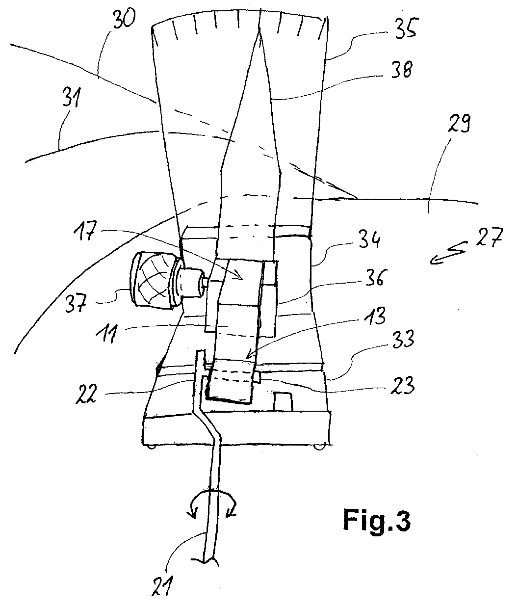
- Fig. 3 it can be seen as an angle disc support device 27 is mounted on a windshield 29 of a motor vehicle. outlined indicated are also the hood 30 together with the hood edge 31 to the windscreen 29, which extend to the left.
- the angle disc support device 27 has a base plate 33 on, at the rear end of the body part 34 connects, the one upwardly projecting angle scale 35 carries. These three parts are rigid and firmly connected. On the body part 34 is rotatable a Receiving device 36 is arranged. The axis of rotation extends parallel to the base plate 33 and perpendicular to the mounting part 34 and to the angle scale 35.
- the adapter 11th used on which, as shown in Fig. 2, the wiper arm 21 is scheduled.
- a clamping screw 37 which in the receiving depression 19 engages, the adapter 11 is on the receiving device 36 attached.
- the twisted Recording device 36 By rotating the wiper arm 21 about its longitudinal axis and by the power transmission by means of the adapter 11, the twisted Recording device 36 about its axis of rotation.
- the pointer wanders 38 along the angle scale 35 and shows the angle of rotation of the wiper arm 21 with respect to the angle disc support device 27th and thus with respect to the windscreen 39.
- the angle with which the wiper arm 21 to the windscreen 29 and thus also the Windscreen wiper itself and the windscreen wiper rubber to the windscreen 29 can now be adjusted by the fact that the Wiper arm 21 is rotated about its longitudinal axis, for example with the help of tools, which offset two Positions on the wiper arm 21 attacks.
- angles respectively have to be different. These angles can be used in tables for each of the different types be set and used as needed to make the respective exact setting.
- the windshield wiper arm 21 opposite the windscreen 29 in the device 27 also be installed a dynamometer. This can be on the device 27 itself or on the receiving device 36 may be provided.
- a dynamometer can be on the device 27 itself or on the receiving device 36 may be provided.
- FIG. 4 a further embodiment of an adapter 111 is shown. It It can be seen how the left receiving area 17 identical to the Adapter 11 is formed from Fig. 1, namely oblong with rectangular Cross-section and with the intake counterbore 119.
- the arm portion 13 is designed differently for receiving a special wiper arm. Namely, there is provided a groove 140 into which a corresponding Projection of the wiper arm engages. Will the clamping screw 142 twisted, as can be seen for comparison in Fig. 5, so can a Clamping an overlying area of the wiper arm respectively. In this case, the diameter of the clamping screw 142 extend slowly and steadily to allow for clamping.
- FIG. Another embodiment of an adapter 211 is shown in FIG. Again, the left receiving area 217 is again formed identical.
- the right arm portion 213 has a spring loaded latch 244 on.
- a corresponding Part of a windshield wiper arm, not shown attached or be fastened by latching is shown in FIG.
- FIG. Another embodiment of an adapter 211 is shown in FIG. Again, the left receiving area 217 is again formed identical.
- the right arm portion 213 has a spring loaded latch 244 on.
- the construction of the adapter is relatively simple can be held. So it is possible to have a set of many different ones Adapters to produce at a relatively low cost, each with the Arm area specially adapted to different windscreen wiper arms are. With the standardized trained recording areas can to a device, such as an angle disc support device 27 as shown in FIG. 3, coupled or attached thereto. With the devices 27 then, for example, the support bracket of the windscreen wiper arm or its windscreen wiper for Windscreen, also to the rear window, of a car measured become. The adjustment of this support angle can be done when the Wiper arm is coupled to the device 27.
- the angle disc support device 27 To the structure of the angle disc support device 27 is still too say that this is also relatively simple. Furthermore can be seen from it, that the base plate 33 firmly on the windscreen 29 can rest without moving parts. A movement of the Scheibenwischerarms 21 relative to the device 27 takes place only on the receiving device 36 instead, which is rotatably mounted. Thus would be it is also possible in a further embodiment of the invention, the receiving device 36 so that they from the base plate 33 and the body part 34 is easily removable. Then, instead of receiving device 36 with the pointer 38 another recording device with a pressure measuring device are attached. Thus, here too a system relatively easy to use and modular.
- Receiving device 36 may be provided by the device 27, this coupled by means of the adapter 11 to the windscreen wiper arm and at another facility, for example for measurement of pad pressure to fasten. So it is only necessary once, the Windscreen wiper arm 21 via an adapter 11 to a receiving device 36 to couple. If instead of the angle, as shown in Fig. 3, the contact pressure can be measured, then a coupling of the Receiving device 36 to a pressure measuring device.
- FIG. 7 shows a tool 40 for interlacing windscreen wiper arms 21 or 321.
- the left end has a metallic head 43 with a slot for overlapping the dashed lines shown Scheibenwischerarms 21.
- the slot is covered with plastic 44.
- the right end has a thread 46. About this becomes a counterpart 48 inserted with a corresponding opening. Then that will be Thread 46 through an opening in the U-shaped wiper arm 321 plugged. Subsequently, the counterpart 50 with a corresponding Internal thread screwed onto the thread 46 of the rod 41. Thus, the windshield wiper arm 321 is firmly connected to the tool 40 and then can be bent.
Landscapes
- Engineering & Computer Science (AREA)
- Mechanical Engineering (AREA)
- Force Measurement Appropriate To Specific Purposes (AREA)
- Details Of Measuring And Other Instruments (AREA)
- Automobile Manufacture Line, Endless Track Vehicle, Trailer (AREA)
- Length Measuring Devices With Unspecified Measuring Means (AREA)
Abstract
Ein Adapter (11) oder ein Set von mehreren solchen Adaptern zur Verbindung
eines Scheibenwischerarms (21) mit einer Aufnahmeeinrichtung
(36) eines Messgeräts (27) zur Einstellung des Winkels des Scheibenwischerarms
zu einer Windschutzscheibe eines Automobils weist zwei
Bereiche (13, 17) auf, mit denen er einerseits mit unterschiedlichen
Scheibenwischerarmen und andererseits mit der Aufnahmeeinrichtung
verbunden wird. Verschiedene Adapter sitzen dabei jeweils angepasst
an unterschiedlich ausgebildeten Scheibenwischerarmen. Des weiteren
weist ein System zur Einstellung eines Scheibenwischerarms eine Erfassung
eines Winkels zwischen Scheibenwischerarm und Scheibe auf.
Description
Die Erfindung betrifft einen bzw. mehrere Adapter zur Kopplung eines Scheibenwischerarms an eine Aufnahmeeinrichtung eines Messgeräts oder eines Einstellgeräts sowie ein solches Gesamtsystem.The invention relates to one or more adapters for coupling a Wiper arm to a receiving device of a measuring device or a setting device and such a total system.
Aus der DE 195 35 048 A1 ist bekannt, von welcher Bedeutung beispielsweise der Auflagewinkel des Scheibenwischerblattes auf der Scheibe ist. Verändert werden kann dieser beispielsweise durch Verdrehen des Scheibenwischerarmes. Dieser kann in ein Einstellgerät eingespannt werden, wodurch sein Winkel ablesbar ist. Durch Ansetzen eines Schraubenschlüssels oder eines anderen Werkzeugs an das Einstellgerät kann ein gewünschter Winkel eingestellt werden. From DE 195 35 048 A1 it is known what significance, for example the bearing angle of the windscreen wiper blade on the Disc is. This can be changed, for example, by twisting the windscreen wiper arm. This can be clamped in a setting device become, whereby his angle is readable. By applying a Wrench or other tool to the setting device a desired angle can be set.
Nachteilig bei dem vorbeschriebenen Einstellgerät ist, dass die Einspannung des Scheibenwischerarms an dem Einstellgerät für verschiedene Typen von Scheibenwischerarmen nicht immer mit der gewünschten Präzision möglich ist. Des weiteren greift die zur Verdrehung aufzubringende Kraft nicht direkt, sondern nur über die Einspannung an dem Einstellgerät indirekt an dem Scheibenwischerarm an.A disadvantage of the above-described setting device is that the clamping the wiper arm on the setting for different Types of windscreen wiper arms not always with the desired Precision is possible. Furthermore, the applied for twisting attacks Force not directly, but only on the clamping on the Adjustment device indirectly on the windscreen wiper arm.
Es werden auch immer mehr Scheibenwischer entwickelt, die eine andere Konstruktion des Scheibenwischerarms aufweisen, insbesondere ohne Gestänge. Diese sind beispielsweise von der Fa. Robert Bosch unter der Bezeichnung "Aero-Wischer" auf dem Markt.It is also being developed more and more wipers, the other Have construction of the wiper arm, in particular without Linkage. These are, for example, from the company. Robert Bosch under the term "Aero-wiper" on the market.
Der Erfindung liegt die Aufgabe zugrunde, einen eingangs genannten Adapter sowie ein eingangs genanntes System zu schaffen, mit denen die Nachteile des Standes der Technik vermieden werden können und insbesondere die Kopplung eines Scheibenwischerarms an ein Messgerät oder Einstellgerät verbessert und eine genaue Messung oder Einstellung an dem Scheibenwischerarm vorgenommnen werden können.The invention is based on the object, an aforementioned Adapter and to provide an aforementioned system, with which the disadvantages of the prior art can be avoided and in particular the coupling of a windscreen wiper arm to a measuring device or adjusting device improves and accurate measurement or adjustment can be performed on the windscreen wiper arm.
Gelöst wird diese Aufgabe durch einen Adapter mit den Merkmalen des
Anspruchs 1, ein Set von mehreren Adaptern mit den Merkmalen des
Anspruchs 12 sowie ein System mit den Merkmalen des Anspruchs 13.
Vorteilhafte sowie bevorzugte Ausgestaltungen der Erfindung sind Gegenstand
der weiteren Ansprüche und werden im folgenden näher erläutert.
Dabei wird auf Merkmale eingegangen, die sowohl bei einem Adapter
in Alleinstellung als auch einem Set von Adaptern oder dem genannten
System verwendet werden können. Der Wortlaut der Ansprüche wird
durch ausdrückliche Bezugnahme zum Inhalt der Beschreibung gemacht. This problem is solved by an adapter with the features of
Anspruchs 1, a set of multiple adapters with the features of
Claim 12 and a system with the features of
Ein erfindungsgemäßer Adapter ist dazu ausgebildet, einen Scheibenwischerarm an eine Aufnahmeeinrichtung oder Aufnahme eines Geräts anzukoppeln, wobei das Gerät zum Vermessen und/oder zum Einstellen des Scheibenwischerarms geeignet sein kann. Beispielsweise können Anstellwinkel eines Scheibenwischers, welcher am Ende des Scheibenwischerarms befestigt ist, oder Anpressdruck des Scheibenwischers gegen die Scheibe erfasst und gegebenenfalls eingestellt oder korrigiert werden. Vorteilhaft wird der Scheibenwischer vor der Ankopplung von dem Scheibenwischerarm abgenommen.An inventive adapter is adapted to a windshield wiper arm to a recording device or recording a device coupled, the device for surveying and / or for setting the wiper arm may be suitable. For example, you can Incident angle of a windshield wiper, which at the end of the wiper arm is attached, or contact pressure of the windscreen wiper against the disc is detected and optionally adjusted or corrected become. Advantageously, the windshield wiper before the coupling of the windscreen wiper arm removed.
Der Adapter weist einen ersten sogenannten Arm-Bereich auf, mit welchem der Adapter an dem Scheibenwischerarm befestigt wird. Des weiteren weist der Adapter einen zweiten sogenannten Aufnahme-Bereich auf, mit dem er an die Aufnahmeeinrichtung angekoppelt bzw. damit verbunden wird.The adapter has a first so-called arm area, with which the adapter is attached to the wiper arm. Furthermore the adapter has a second so-called recording area on, with which he coupled to the receiving device or connected to it becomes.
Mit einem solchen erfindungsgemäßen Adapter ist es vorteilhaft möglich, die Aufnahmeeinrichtung sozusagen normiert bzw. nur in einer einzigen Version herzustellen und gleichzeitig beliebig unterschiedlich ausgebildete Scheibenwischerarme fest und sicher daran anzukoppeln. Der erste Arm-Bereich sowie der zweite Aufnahme-Bereich können speziell für den beabsichtigten Zweck ausgebildet sein, so dass die jeweiligen Befestigungen angepasst und mechanisch sehr stabil ausgebildet sein können. Es werden jeweils nur unterschiedliche Adapter benötigt, welche beispielsweise aus einem erfindungsgemäßen Set von Adaptern ausgewählt werden können, um einen beliebigen Scheibenwischerarm passgenau mit der Aufnahmeeinrichtung bzw. dem Mess- oder Einstellgerät zu verbinden. Vorteilhaft weisen alle möglichen Adapter im Rahmen der Erfindung, welche insbesondere zu dem vorgenannten Set gehören können, einen zweiten Aufnahme-Bereich auf, der immer gleich ist. With such an adapter according to the invention it is advantageously possible the recording device standardized, so to speak, or only in a single Version produce and at the same time arbitrarily differently trained Firmly and securely attach windscreen wiper arms to it. Of the first arm area as well as the second recording area can be special be designed for the intended purpose, so that the respective Fasteners adapted and mechanically very stable trained can. Only different adapters are needed each time for example, from a set of adapters according to the invention can be selected to any windscreen wiper arm fit with the receiving device or the measuring or setting device connect to. Advantageously, all sorts of adapters in the frame of the invention, which belong in particular to the aforementioned set You can set a second recording area that is always the same is.
Besonders vorteilhaft erfolgt eine Befestigung des Adapters mit dem ersten Arm-Bereich an einem Ende des Scheibenwischerarms bzw. an der Stelle, an der auch der Scheibenwischer daran befestigt ist. So kann versucht werden, möglichst die gleiche Befestigung des Adapters mit dem ersten Arm-Bereich an dem Scheibenwischerarm zu erreichen wie der Scheibenwischer selber. Hierzu sollte die Befestigung jeweils gleich ausgebildet sein. Dabei kann der erste Arm-Bereich Ausnehmungen und/oder Vorsprünge aufweisen, welche zu der Ausbildung des Scheibenwischerarms für die Befestigung des Scheibenwischers korrespondieren. Wird ein Scheibenwischerarm mit einer Bohrung auf einen Zapfen am Scheibenwischerarm aufgesteckt, so sollte der erste Arm-Bereich dieselbe oder zumindest eine entsprechende Bohrung aufweisen.Particularly advantageous is a fastening of the adapter to the first Arm area at one end of the wiper arm or at the Place where the windshield wiper is attached. So can try to use the same attachment as possible with the adapter to reach the first arm area on the wiper arm like the windshield wiper itself. For this purpose, the attachment should be the same be educated. In this case, the first arm area recesses and / or have projections which contribute to the formation of the windscreen wiper arm correspond to the attachment of the windscreen wiper. Will a windscreen wiper arm with a hole on a pin attached to the wiper arm, so should the first arm area have the same or at least one corresponding hole.
Die Befestigung des Arm-Bereichs an dem Scheibenwischerarm ist bei einer einfachen Ausführung vorteilhaft steckbar ausgebildet. So ist es möglich, ohne zusätzliche bewegliche Teile, beispielsweise Verriegelungs- oder Klemmteile, auszukommen. Eine derartige Befestigung geht sehr schnell. Schließlich ist sie nicht denselben Belastungen ausgesetzt wir ein Scheibenwischer in Betrieb, also beispielsweise dem Fahrtwind bei hohen Geschwindigkeiten.The attachment of the arm area to the windscreen wiper arm is included a simple design advantageously designed pluggable. That's the way it is possible without additional moving parts, such as locking or clamping parts, to get along. Such attachment goes very fast. After all, she is not exposed to the same burdens a windshield wiper in operation, so for example the wind at high speeds.
Bei einer alternativen Ausführungsform der Erfindung ist der Arm-Bereich mit einer breiten Öffnung für eine Klemmung, vorteilhaft seitlich mittels einer Klemmschraube, ausgebildet. So können auch solche Scheibenwischerarme eingespannt werden, welche ansonsten nicht in gängige Maße passen, beispielsweise weil sie zu groß sind.In an alternative embodiment of the invention, the arm region is with a wide opening for a clamping, advantageous laterally by means of a clamping screw formed. So can such Wiper arms are clamped, which are not otherwise in common dimensions fit, for example because they are too big.
Ein möglichst normiert ausgebildeter zweiter Aufnahme-Bereich des Adapters kann mit einer relativ einfachen geometrischen Grundform ausgebildet sein. Insbesondere kann er zylindrisch sein bzw. einen zylindrisehen Abschnitt aufweisen, der vorteilhaft viereckig sein kann. So wird eine gewisse Verwindungssteifigkeit bzw. Verdrehfestigkeit gegeben.A standardized as possible trained second recording area of the adapter can be designed with a relatively simple basic geometric shape be. In particular, it may be cylindrical or a cylindrical Section have, which can be advantageous quadrangular. So will given a certain torsional rigidity or torsional strength.
Des weiteren ist der zweite Aufnahme-Bereich vorteilhaft mit der Aufnahmeeinrichtung zusammen derart ausgebildet, dass eine Steckverbindung hergestellt werden kann. Besonders vorteilhaft wird der Aufnahme-Bereich in eine Ausnehmung in der Aufnahmeeinrichtung eingesteckt.Furthermore, the second receiving area is advantageous with the receiving device together designed such that a connector can be produced. Particularly advantageous is the recording area inserted into a recess in the receiving device.
Bei einer vorteilhaften Ausführung des Adapters ist er länglich. An zwei Endbereichen, insbesondere an gegenüberliegenden Endbereichen, sind jeweils Arm-Bereich und Aufnahme-Bereich vorgesehen. Zur einfacheren Herstellung, insbesondere auch Bedienung, ist ein Adapter einteilig ausgebildet, insbesondere dann, wenn die Befestigung an dem Scheibenwischerarm relativ einfach erfolgen kann. Vorteilhaft ist er einstückig ausgeführt, wobei es besonders vorteilhaft ist, wenn keine bewegbaren Teile daran vorgesehen sind. Ein solcher Adapter ist relativ einfach in der Herstellung und vor allem im Gebrauch. Durch den Verzicht auf bewegbare Teile ist der Einsatz in verhältnismäßig rauen Umgebungen wie Werkstätten oder Tankstellen möglich.In an advantageous embodiment of the adapter, it is elongated. At two End areas, in particular at opposite end areas, each arm-area and recording area are provided. For the easier Production, especially operation, an adapter is one-piece formed, in particular when the attachment to the Windscreen wiper arm can be done relatively easily. It is advantageous made in one piece, it being particularly advantageous if no movable parts are provided thereto. Such an adapter is relative easy to manufacture and above all in use. By the renunciation on moving parts is the use in relatively harsh environments like workshops or gas stations possible.
Das Einstellen oder Korrigieren des Scheibenwischerarms erfolgt durch Verdrehen oder Verbiegen. Dazu ist eine gewisse Kraft notwendig, die nicht auf seine Lagerung wirken sollte, sondern nur innerhalb des Scheibenwischerarms zu einer Verformung führen sollte. Hier können für Scheibenwischerarme mit schmalem bzw. dünnem Profil zwei Werkzeuge verwendet werden, welche entsprechende schlitzförmige Ausnehmungen aufweisen, mit denen der Arm an zwei Stellen in gewissem Abstand voneinander übergriffen und verbogen werden kann. Diese Werkzeuge stellen so eine eigene erfinderische Idee dar, die unabhängig von dem vorher beschriebenen ist. Die Werkzeuge können beispielsweise aus Metall oder sehr stabilem Material sein, im Bereich der Ausnehmungen, insbesondere zur direkten Anlage, jedoch mit Kunststoff ummantelt sein oder solchen aufweisen. So ist es möglich, die Oberflächen der Scheibenwischerarme zu schonen. Die Werkzeuge können auch an beiden Enden einer langen Stange odgl. jeweils verschieden ausgebildete Ausnehmungen aufweisen, beispielsweise mit unterschiedlicher Breite.Adjusting or correcting the windscreen wiper arm is done by Twisting or bending. This requires a certain amount of force, the should not affect its storage, but only within the Wiper arm should lead to deformation. here we can for windscreen wiper arms with narrow or thin profile two tools be used, which corresponding slot-shaped recesses with which the arm in two places in some Distance can be overlapped and bent. These Tools are thus an inventive idea that is independent of which previously described. The tools can, for example be made of metal or very stable material in the field of Recesses, in particular for direct installation, but with plastic be encased or have such. So it is possible the surfaces to protect the windscreen wiper arms. The tools can also at both ends of a long rod or the like. each different have trained recesses, for example, with different Width.
Bei einer weiteren erfinderischen Ausführung der Werkzeuge können diese nicht mit einer schlitzförmigen Ausnehmung versehen sein. Sie sind mit einem in Stangenrichtung weisenden Gewinde und einem dagegen verschraubbaren Gegenstück versehen. Dabei sind Stangenende und Gegenstück so ausgebildet dass das Gegenstück zum Eingreifen in ein U-förmiges Profil eines Scheibenwischerarms geeignet ist, und zwar an der Seite des Profils zwischen den beiden Schenkeln, wobei durch Öffnungen in dieser Seite das Gewinde des Stangenendes gesteckt wird. Hier wäre ein Werkzeug mit schlitzförmiger Öffnung unbrauchbar. Mit dem Gegenstück wird die Stange an dem Profil so fest verschraubt, dass wiederum mit zwei solchen Werkzeugen in einem gewissen Abstand voneinander ein Verschränken oder Verbiegen möglich ist.In a further inventive embodiment of the tools can these should not be provided with a slot-shaped recess. she are with a pointing in the bar direction thread and one against screwed counterpart provided. Here are rod end and counterpart designed so that the counterpart to intervene in a U-shaped profile of a wiper arm is suitable, namely at the side of the profile between the two legs, passing through Openings in this side put the thread of the rod end becomes. Here, a tool with a slot-shaped opening would be useless. With the counterpart, the rod is screwed to the profile so tight that in turn with two such tools at a certain distance interlocking or bending is possible.
Zusätzlich kann noch zur besseren Befestigung über das Gewinde ein Passungs-Stück geführt werden, welches an dem Profil des Scheibenwischerarms flächig anliegt und es eventuell sogar U-förmig übergreift, um eine möglichst gute Anlage zur Krafteinleitung zu erhalten. So wird das Profil zwischen dem Passungs-Stück und dem Gegenstück gehalten. Das Passungs-Stück kann eine Oberfläche aus Kunststoff aufweisen oder ganz aus Kunststoff sein, um die sichtbare Seite des Scheibenwischerarms nicht zu verkratzen.In addition, for better attachment via the thread Passungs piece to be performed, which on the profile of the wiper arm flat and possibly it even U-shaped overlaps, to get the best possible plant for the introduction of force. So will held the profile between the fitting piece and the counterpart. The fit piece may have a plastic surface or entirely plastic to the visible side of the wiper arm not to scratch.
Die vorgenannten Geräte zur Vermessung und/oder Einstellung eines Scheibenwischerarms können beispielsweise auf zwei unterschiedliche Arten ausgebildet sein. Zur Messung beispielsweise einer Winkelauflage des Scheibenwischerarms gegenüber der Scheibe, insbesondere was die spätere entsprechende Stellung des Scheibenwischergummis betrifft, kann eine Winkel-Scheibenauflageeinrichtung vorgesehen sein. Daran ist eine Winkel-Aufnahmeeinrichtung drehbar gelagert, welche einer vorbeschriebenen Aufnahmeeinrichtung entsprechen kann. So ist mittels eines vorgenannten Adapters ein Scheibenwischerarm daran ankoppelbar oder befestigbar. Des weiteren sind Mittel vorgesehen, mit denen ein Winkel bzw. Drehwinkel zwischen der Winkel-Aufnahmeeinrichtung und der Winkel-Scheibenauflageeinrichtung erfasst werden kann.The aforementioned devices for measuring and / or setting a Windscreen wiper arm can, for example, on two different Species be trained. For measuring, for example, an angle support the wiper arm against the disc, in particular what the later corresponding position of the wiper blade rubber, An angle disc support device may be provided. At an angle receiving device is rotatably mounted, which may correspond to a prescribed recording device. So is a wiper arm can be coupled thereto by means of an aforementioned adapter or attachable. Furthermore, funds are provided with which an angle or angle of rotation between the angle-receiving device and the angle disc support device are detected can.
Weiter sind für die Bestimmung des Anpressdrucks, mit welchem ein Scheibenwischerarm insbesondere mit anmontiertem Scheibenwischer im Betrieb gegen die Scheibe drückt, eine Druck-Scheibenauflageeinrichtung und eine Kraft-Messeinrichtung vorgesehen. An der Druck-Scheibenauflageeinrichtung ist eine Druck-Aufnahmeeinrichtung bewegbar angeordnet, welche einer vorgenannten Aufnahmeeinrichtung entsprechen kann. Über einen speziell ausgebildeten Adapter, beispielsweise auf vorgenannte Art und Weise, ist der Scheibenwischerarm an der Druck-Aufnahmeeinrichtung ankoppelbar. Des weiteren ist die Druck-Aufnahmeeinrichtung über die Kraft-Messeinrichtung derart mit der Druck-Scheibenauflageeinrichtung verbunden, dass der Scheibenwischerarm über die Verbindung mit der Druck-Aufnahmeeinrichtung gegen die Scheibe und somit die Druck-Scheibenauflageeinrichtung den Anpressdruck mittels der Kraft-Messeinrichtung erfassbar macht. Der Druck kann über Piezo-Sensoren oder Dehnungs-Meßstreifen gemessen werden.Next are for the determination of the contact pressure, with which a Wiper arm, in particular with mounted windshield wiper in operation against the disc presses, a pressure disc support device and a force-measuring device provided. At the pressure disc support device a pressure-receiving device is movable arranged, which correspond to an aforementioned receiving device can. About a specially trained adapter, for example in the aforementioned manner, the windscreen wiper arm is on the pressure-receiving device can be coupled. Furthermore, the Pressure-receiving device via the force-measuring device with so the pressure disc support device connected to the windshield wiper arm over the connection with the pressure receiving device against the disc and thus the pressure disc support device the Makes contact pressure by means of the force-measuring device detectable. Of the Pressure can be measured via piezo sensors or strain gauges become.
Die Befestigung des Adapters an dem Aufnahme-Bereich an einer Aufnahmeeinrichtung sollte kraftschlüssig sein und relativ leicht lösbar. Möglichkeiten sind hier eine Klemmfeder oder Klemmschraube. Dadurch sind in gewissem Maß noch Toleranzausgleiche möglich. The attachment of the adapter to the receiving area on a receiving device should be non-positive and relatively easy to solve. Possibilities here are a clamping spring or clamping screw. Thereby To a certain extent, tolerance compensation is still possible.
Die Scheibenauflageeinrichtung ist vorteilhaft derart ausgebildet, dass sie auf einer Fläche, wie beispielsweise einer Motorhaube, welche horizontal oder leicht geschrägt ist, stabil steht, ohne umzufallen. So kann sie zur besseren Handhabung und Vorbereitung der Messung dort abgestellt werden. Vorteilhaft weist die Scheibenauflageeinrichtung mehrere, insbesondere mindestens drei, Auflagepunkte auf. Diese sind vorteilhaft fest angeordnet und nicht beweglich, insbesondere möglichst wenig elastisch. Ansonsten könnte eine Messung verfälscht werden.The disc support device is advantageously designed such that on a surface, such as a hood, which is horizontal or is slightly skewed, stable, without falling over. So can they are parked there for better handling and preparation of the measurement become. Advantageously, the disc support device has several, in particular at least three points of contact. These are advantageous firmly arranged and not movable, in particular as little as possible elastic. Otherwise, a measurement could be falsified.
Es ist vorteilhaft, wenn die Mittel zur Erfassung des Drehwinkels derart ausgebildet sind, dass ein Ablesen, beispielsweise von einer entsprechenden Skala, zumindest von derjenigen Seite aus möglich ist, an welche der Scheibenwischerarm heranreicht. Dies ermöglicht es, die vorschriftsmäßige Befestigung des Scheibenwischerarms daran zu überwachen und gleichzeitig den Drehwinkel zu bestimmen. Insbesondere gilt diese Ablesbarkeit auch für eine Kraft-Messeinrichtung. Noch vorteilhafter ist es natürlich, die Messwerte von zwei Seiten aus ablesen zu können.It is advantageous if the means for detecting the angle of rotation so are formed so that a reading, for example from a corresponding Scale, at least from that side is possible to which the windscreen wiper arm comes up. This makes it possible to comply with the regulations Attachment of the wiper arm to monitor and at the same time to determine the angle of rotation. Especially This readability also applies to a force measuring device. Even more advantageous it is natural to read the readings from two sides can.
Bei einer besonders bevorzugten Ausgestaltung der Erfindung sind die Geräte in einer Einheit vorhanden. So ist eine gemeinsame Scheibenauflageeinrichtung vorgesehen. Des weiteren ist es dann möglich, mit einer einzigen Kopplung des Scheibenwischerarms an die Einrichtung einen Auflagewinkel und einen Anpressdruck zu ermitteln, gegebenenfalls sogar in einem Schritt. Dieses macht nicht nur ein schnelleres Arbeiten möglich. Ein besonders großer Vorteil liegt darin, dass bei einer gegebenenfalls möglichen Veränderung des Auflagewinkels und des Anpressdrucks der jeweils andere Wert überwacht werden kann und so ein aufwendiger Justiervorgang, der durch zwei unterschiedliche Faktoren beeinflusst wird, vereinfacht werden kann. In a particularly preferred embodiment of the invention, the Devices in one unit available. So is a common disc support device intended. Furthermore, it is possible with a single coupling of the wiper arm to the device to determine a support angle and a contact pressure, if necessary even in one step. This not only makes working faster possible. A particularly big advantage is that at one possibly possible change in the support angle and the Contact pressure of the other value can be monitored and so a complex adjustment process by two different factors is influenced, can be simplified.
Diese und weitere Merkmale gehen außer aus den Ansprüchen auch aus der Beschreibung und den Zeichnungen hervor, wobei die einzelnen Merkmale jeweils für sich allein oder zu mehreren in Form von Unterkombinationen bei einer Ausführungsform der Erfindung und auf anderen Gebieten verwirklicht sein und vorteilhafte sowie für sich schutzfähige Ausführungen darstellen können, für die hier Schutz beansprucht wird. Die Unterteilung der Anmeldung in einzelne Abschnitte sowie Zwischen-Überschriften beschränken die unter diesen gemachten Aussagen nicht in ihrer Allgemeingültigkeit.These and other features go beyond the claims as well from the description and the drawings, the individual Characteristics in each case alone or in the form of sub-combinations in one embodiment of the invention and on others Be realized and beneficial and protectable areas Represent embodiments for which claims protection here becomes. The subdivision of the application into individual sections as well as intermediate headings restrict the statements made thereunder not in its generality.
Ausführungsbeispiele der Erfindung sind in den Zeichnungen schematisch dargestellt und werden im folgenden näher erläutert. In den Zeichnungen zeigen:
- Fig. 1
- eine Seitenansicht eines ersten Adapters,
- Fig. 2
- eine Draufsicht von oben auf den Adapter aus Fig. 1 mit angesetztem Scheibenwischerarm,
- Fig. 3
- eine skizzierte Darstellung einer Winkel-Scheibenauflageeinrichtung mit über den Adapter aus Fig. 1 befestigtem Scheibenwischerarm auf einer Frontscheibe,
- Fig. 4
- eine Seitenansicht eines zweiten Adapters mit Klemmschrauben,
- Fig. 5
- die Darstellung aus Fig. 4 mit verdrehter Klemmschraube,
- Fig. 6
- eine Seitenansicht eines dritten Adapters mit einer federnden Rasteinrichtung und
- Fig. 7
- eine Schrägansicht eines Werkzeuges mit zwei unterschiedlichen Enden zum Verschränken eines Scheibenwischerarms.
- Fig. 1
- a side view of a first adapter,
- Fig. 2
- a top view of the adapter of FIG. 1 with attached windshield wiper arm,
- Fig. 3
- 2 shows a sketch of an angle disk support device with a windshield wiper arm fastened via the adapter from FIG. 1 on a windscreen, FIG.
- Fig. 4
- a side view of a second adapter with clamping screws,
- Fig. 5
- the representation of FIG. 4 with twisted clamping screw,
- Fig. 6
- a side view of a third adapter with a resilient latching device and
- Fig. 7
- an oblique view of a tool with two different ends for interleaving a wiper arm.
In Fig. 1 ist ein erster Adapter 11 in Seitenansicht dargestellt. Der Adapter
11 weist an seinem rechten Teil den Arm-Bereich 13 auf. Dieser ist
leicht nach unten abgewinkelt und trägt am Ende eine Arm-Bohrung 15.In Fig. 1, a
Am linken Teil weist der Adapter 11 den Aufnahme-Bereich 17 auf mit
einer Aufnahme-Senkung 19. In die Aufnahme-Senkung 19 greift eine
Klemmschraube einer Aufnahmeeinrichtung und sorgt so für eine punktgenaue
und sichere Befestigung.On the left part of the
Aus der Draufsicht in Fig. 2 ist zu erkennen, wie ein Scheibenwischerarm
21 mit einem Armende 22 und einem davon rechtwinklig abstehenden
Scheibenwischerbolzen 23 an dem Adapter 11 befestigt ist. Dazu
wird der Adapter 11 mit der Arm-Bohrung 15 auf den Scheibenwischerbolzen
23 gesteckt. Eine weitere Befestigung ist nicht nötig. Durch diese
Art der Befestigung ist eine Verdrehung von Adapter 11 und Scheibenwischerarm
21 um ihre Längsachse ausgeschlossen. Durch die Art der
Befestigung des Adapters 11 an der Aufnahmeeinrichtung stört auch die
Verschwenkbarkeit der beiden Teile um den Scheibenwischerbolzen 23
nicht. Dies wird im weiteren noch genauer erläutert.From the plan view in Fig. 2 can be seen as a
In Fig. 3 ist zu erkennen, wie eine Winkel-Scheibenauflageeinrichtung
27 auf eine Frontscheibe 29 eines Kraftfahrzeugs aufgesetzt ist. Skizziert
angedeutet sind dabei auch die Motorhaube 30 samt der Motorhaubenkante
31 zur Frontscheibe 29 hin, welche sich nach links erstrecken.In Fig. 3 it can be seen as an angle
Die Winkel-Scheibenauflageeinrichtung 27 weist eine Grundplatte 33
auf, an der sich am hinteren Ende der Aufbauteil 34 anschließt, der eine
nach oben ragende Winkelskala 35 trägt. Diese drei Teile sind starr und
fest miteinander verbunden. An dem Aufbauteil 34 ist verdrehbar eine
Aufnahmeeinrichtung 36 angeordnet. Die Drehachse erstreckt sich dabei
parallel zur Grundplatte 33 und senkrecht zum Aufbauteil 34 bzw.
zur Winkelskala 35. In die Aufnahmeeinrichtung 36 ist der Adapter 11
eingesetzt, an dem, wie in Fig. 2 dargestellt ist, der Scheibenwischerarm
21 angesetzt ist. Mittels einer Klemmschraube 37, welche in die Aufnahme-Senkung
19 eingreift, ist der Adapter 11 an der Aufnahmeeinrichtung
36 befestigt. Des weiteren steht von der Aufnahmeeinrichtung
36 senkrecht nach oben und somit in etwa parallel zur Winkelskala 35
ein Zeiger 38 ab. An diesem kann, wie zu erkennen ist, ein Winkel am
oberen Ende der Winkelskala 35 abgelesen werden.The angle
Durch Verdrehen des Scheibenwischerarms 21 um seine Längsachse
und durch die Kraftübertragung mittels des Adapters 11 verdreht sich die
Aufnahmeeinrichtung 36 um ihre Drehachse. Dabei wandert der Zeiger
38 entlang der Winkelskala 35 und zeigt den Drehwinkel des Scheibenwischerarms
21 gegenüber der Winkel-Scheibenauflageeinrichtung 27
und somit gegenüber der Frontscheibe 39 an. Der Winkel, mit welchem
der Scheibenwischerarm 21 zu der Frontscheibe 29 und somit auch der
Scheibenwischer selber sowie der Scheibenwischergummi zur Frontscheibe
29 stehen, kann nun dadurch eingestellt werden, dass der
Scheibenwischerarm 21 um seine Längsachse verdreht wird, beispielsweise
durch Zuhilfenahme von Werkzeug, welches an zwei versetzten
Stellen an den Scheibenwischerarm 21 angreift. In dem dazwischenliegenden
Abschnitt kann dann der Scheibenwischerarm 21 tordiert bzw.
um seine Längsachse verdreht werden und so der Winkel eingestellt
werden. Dabei ist es möglich, dass der Scheibenwischerarm 21 mittels
des Adapters 11 an die Winkel-Scheibenauflageeinrichtung 27 angekoppelt
bleibt, um die Einstellung des Winkels genau vornehmen zu
können.By rotating the
Es ist selbstverständlich, dass für verschiedene Fahrzeuge und/oder verschiedene Konstruktionen von Scheibenwischerarmen die Winkel jeweils unterschiedlich sein müssen. Diese Winkel können in Tabellen für jeweils die unterschiedlichen Typen festgelegt sein und bei Bedarf herangezogen werden, um die jeweilige genaue Einstellung vorzunehmen.It goes without saying that for different vehicles and / or different constructions of windscreen wiper arms the angles respectively have to be different. These angles can be used in tables for each of the different types be set and used as needed to make the respective exact setting.
Aus der Fig. 3 ist auch zu erkennen, dass die Verdrehbarkeit von Scheibenwischerarm
21 zu Adapter 11 über den Scheibenwischerbolzen 23
nicht stört. Durch die feste und unbewegliche Aufnahme des Adapters
11 mit dem Aufnahme-Bereich 17 in der Aufnahmeeinrichtung 36 kann
hierüber keine Bewegung stattfinden.From Fig. 3 it can also be seen that the rotatability of
In weiterer Ausgestaltung der Erfindung könnte zur Messung des Auflagedrucks
des Scheibenwischerarm 21 gegenüber der Frontscheibe 29 in
der Einrichtung 27 auch noch ein Kraftmesser eingebaut sein. Dieser
kann an der Einrichtung 27 selber oder auch an der Aufnahmeeinrichtung
36 vorgesehen sein. Hier bieten sich sowohl Kraftmesser über Federn
als auch elektrische Kraftmesser an, beispielsweise über Piezo-Elemente.In a further embodiment of the invention could for measuring the contact pressure
the
In Fig. 4 ist eine weitere Ausbildung eines Adapters 111 dargestellt. Es
ist zu erkennen, wie der linke Aufnahme-Bereich 17 identisch zu dem
Adapter 11 aus Fig. 1 ausgebildet ist, nämlich länglich mit rechteckigem
Querschnitt und mit der Aufnahme-Senkung 119. Der Arm-Bereich 13 ist
anders ausgebildet zur Aufnahme eines speziellen Scheibenwischerarms.
Es ist nämlich eine Nut 140 vorgesehen, in die ein entsprechender
Vorsprung des Scheibenwischerarms eingreift. Wird die Klemmschraube
142 verdreht, wie zum Vergleich in Fig. 5 zu erkennen ist, so kann eine
Festklemmung eines darüberliegenden Bereichs des Scheibenwischerarms
erfolgen. Dabei kann sich der Durchmesser der Klemmschraube
142 langsam und stetig erweitern, um eine Festklemmung zu ermöglichen. 4, a further embodiment of an
Eine weitere Ausbildung eines Adapters 211 ist in Fig. 6 dargestellt.
Auch hier ist der linke Aufnahme-Bereich 217 wieder identisch ausgebildet.
Der rechte Arm-Bereich 213 weist eine federgelagerte Rasteinrichtung
244 auf. An dieser Rasteinrichtung 244 kann ein entsprechender
Teil eines nicht dargestellten Scheibenwischerarms angebracht bzw.
durch Rastung befestigt werden.Another embodiment of an
Somit ist aus den Darstellungen einerseits zu entnehmen, wie die Adapter stets auf selbe Art und Weise ausgebildete Aufnahme-Bereiche aufweisen. Die Arm-Bereiche dagegen sind an die jeweiligen Scheibenwischerarme angepasst und können sehr unterschiedliche Befestigungssysteme aufweisen.Thus, it can be seen from the illustrations on the one hand, as the adapter Always have trained in the same way recording areas. The arm areas, however, are to the respective windscreen wiper arms adapted and can be very different fastening systems exhibit.
Des weiteren ist zu erkennen, wie der Aufbau der Adapter relativ einfach
gehalten sein kann. So ist es möglich, einen Satz vieler verschiedener
Adapter zu relativ geringen Kosten herzustellen, die jeweils mit dem
Arm-Bereich speziell auf verschiedene Scheibenwischerarme abgestimmt
sind. Mit den genormt ausgebildeten Aufnahme-Bereichen können
sie an eine Einrichtung, beispielsweise eine Winkel-Scheibenauflageeinrichtung
27 gemäß Fig. 3, angekoppelt bzw. daran befestigt werden.
Mit den Einrichtungen 27 kann dann beispielsweise der Auflagewinkel
des Scheibenwischerarms bzw. seines Scheibenwischers zur
Frontscheibe, ebenfalls auch zur Heckscheibe, eines Autos gemessen
werden. Die Verstellung dieses Auflagewinkels kann erfolgen, wenn der
Scheibenwischerarm an die Einrichtung 27 angekoppelt ist.Furthermore, it can be seen how the construction of the adapter is relatively simple
can be held. So it is possible to have a set of many different ones
Adapters to produce at a relatively low cost, each with the
Arm area specially adapted to different windscreen wiper arms
are. With the standardized trained recording areas can
to a device, such as an angle
Zu dem Aufbau der Winkel-Scheibenauflageeinrichtung 27 ist noch zu
sagen, dass diese ebenfalls relativ einfach aufgebaut ist. Des weiteren
ist daraus zu erkennen, dass die Grundplatte 33 fest auf der Frontscheibe
29 aufliegen kann ohne bewegliche Teile. Eine Bewegung des
Scheibenwischerarms 21 relativ zur Einrichtung 27 findet lediglich über
die Aufnahmeeinrichtung 36 statt, die drehbar gelagert ist. Somit wäre
es in weiterer Ausgestaltung der Erfindung auch möglich, die Aufnahmeeinrichtung
36 so auszubilden, dass sie von der Grundplatte 33 bzw.
dem Aufbauteil 34 leicht entfernbar ist. Dann kann anstelle Aufnahmeeinrichtung
36 mit dem Zeiger 38 eine andere Aufnahmeeinrichtung mit
einer Druckmesseinrichtung angebracht werden. Somit kann auch hier
ein System relativ leicht verwendbar und modular aufgebaut sein.To the structure of the angle
Alternativ kann bei einer konstruktiv vorgesehenen Abnehmbarkeit der
Aufnahmeeinrichtung 36 von der Einrichtung 27 vorgesehen sein, diese
mittels des Adapters 11 an den Scheibenwischerarm festgekoppelt zu
lassen und an einer anderen Einrichtung, beispielsweise zur Messung
des Auflagedrucks, zu befestigen. So ist es nur einmal notwendig, den
Scheibenwischerarm 21 über einen Adapter 11 an eine Aufnahmeeinrichtung
36 zu koppeln. Soll anstelle des Winkels, wie in Fig. 3 dargestellt,
der Auflagedruck gemessen werden, so kann eine Ankopplung der
Aufnahmeeinrichtung 36 an eine Druckmesseinrichtung erfolgen.Alternatively, in a constructive provided removability of
Receiving
Die Fig. 7 zeigt ein Werkzeug 40 zum Verschränken von Scheibenwischerarmen
21 oder 321. Das linke Ende weist einen metallischen Kopf
43 mit einem Schlitz zum Übergreifen des gestrichelt dargestellten
Scheibenwischerarms 21. Der Schlitz ist mit Kunststoff 44 verkleidet.FIG. 7 shows a
Das rechte Ende weist ein Gewinde 46 auf. Über dieses wird ein Gegenstück
48 gesteckt mit einer entsprechenden Öffnung. Dann wird das
Gewinde 46 durch eine Öffnung in dem U-förmigen Scheibenwischerarm
321 gesteckt. Anschließend wird das Gegenstück 50 mit einem entsprechenden
Innengewinde auf das Gewinde 46 der Stange 41 geschraubt.
So wird der Scheibenwischerarm 321 mit dem Werkzeug 40 fest verbunden
und kann dann verbogen werden.The right end has a
Claims (17)
Applications Claiming Priority (2)
| Application Number | Priority Date | Filing Date | Title |
|---|---|---|---|
| DE20314115U DE20314115U1 (en) | 2003-09-09 | 2003-09-09 | Adapter and system for coupling a windscreen wiper arm to a receiving device of a measuring or setting device |
| DE20314115U | 2003-09-09 |
Publications (3)
| Publication Number | Publication Date |
|---|---|
| EP1514751A2 true EP1514751A2 (en) | 2005-03-16 |
| EP1514751A3 EP1514751A3 (en) | 2005-08-17 |
| EP1514751B1 EP1514751B1 (en) | 2007-10-17 |
Family
ID=29558189
Family Applications (1)
| Application Number | Title | Priority Date | Filing Date |
|---|---|---|---|
| EP04019127A Expired - Lifetime EP1514751B1 (en) | 2003-09-09 | 2004-08-12 | Set of adapters for coupling a wiper arm to the holding arrangement of a measuring- or an adjusting-device |
Country Status (4)
| Country | Link |
|---|---|
| EP (1) | EP1514751B1 (en) |
| AT (1) | ATE375903T1 (en) |
| DE (2) | DE20314115U1 (en) |
| ES (1) | ES2295743T3 (en) |
Families Citing this family (2)
| Publication number | Priority date | Publication date | Assignee | Title |
|---|---|---|---|---|
| US8839697B2 (en) | 2011-12-06 | 2014-09-23 | Nissan North America, Inc. | Wiper attack angle adjustment tool |
| DE102013111986B4 (en) * | 2013-10-30 | 2015-11-19 | Christian Ramoser | Adjustment gauge and assembly with setting gauge |
Family Cites Families (6)
| Publication number | Priority date | Publication date | Assignee | Title |
|---|---|---|---|---|
| US1681724A (en) * | 1924-03-10 | 1928-08-21 | D & R Auto Products Company In | Windshield-wiper adjuster |
| DE1907389A1 (en) * | 1969-02-14 | 1970-09-03 | Daimler Benz Ag | Adjustment device |
| DE4002240A1 (en) | 1990-01-26 | 1991-08-01 | Bayerische Motoren Werke Ag | Windscreen wiper blade-setting angle measurer - has mutually movable parts with rotation angle markings enabling measurement without blade removal |
| DE19535048B4 (en) | 1994-10-07 | 2008-05-08 | Volkswagen Ag | Adjustment and measuring device for windscreen wiper arms |
| FR2746355B1 (en) | 1996-03-22 | 1998-04-30 | Valeo Systemes Dessuyage | MOTOR VEHICLE WINDSCREEN WIPER WITH ORIENTATION DEVICE |
| DE19643689A1 (en) * | 1996-10-23 | 1998-04-30 | Teves Gmbh Alfred | Template for visual inspection of the normal error of a wiper arm of a pendulum wiper device |
-
2003
- 2003-09-09 DE DE20314115U patent/DE20314115U1/en not_active Expired - Lifetime
-
2004
- 2004-08-12 DE DE502004005247T patent/DE502004005247D1/en not_active Expired - Lifetime
- 2004-08-12 EP EP04019127A patent/EP1514751B1/en not_active Expired - Lifetime
- 2004-08-12 ES ES04019127T patent/ES2295743T3/en not_active Expired - Lifetime
- 2004-08-12 AT AT04019127T patent/ATE375903T1/en not_active IP Right Cessation
Also Published As
| Publication number | Publication date |
|---|---|
| EP1514751A3 (en) | 2005-08-17 |
| DE502004005247D1 (en) | 2007-11-29 |
| ATE375903T1 (en) | 2007-11-15 |
| EP1514751B1 (en) | 2007-10-17 |
| DE20314115U1 (en) | 2003-11-13 |
| ES2295743T3 (en) | 2008-04-16 |
Similar Documents
| Publication | Publication Date | Title |
|---|---|---|
| EP1353150B1 (en) | Angle detector | |
| EP2331913B1 (en) | Device for the clamping attachment of a scale | |
| DE102017104349A1 (en) | Load cell for a balance | |
| DE2064075C3 (en) | Gauge for checking or measuring the torsion position of turbine blade face parts | |
| DE102015107243B4 (en) | Measuring device for measuring a path and / or a speed and a method for mounting the same | |
| DE19535048B4 (en) | Adjustment and measuring device for windscreen wiper arms | |
| DE1573938C3 (en) | Torque measuring device | |
| DE2539141A1 (en) | Releasable spring catch securing arrangement for electric sensors - for indicating IC engine crankshaft angles, esp. tdc. | |
| EP2570779B1 (en) | Mounting device of a length measurement system | |
| EP1514751A2 (en) | Adapter and system for coupling a wiper arm to the holding arrangement of a measuring- or an adjusting-device | |
| DE102019202763A1 (en) | Measuring device for a vehicle's own weight measurement of a vehicle and vehicle with such a measuring device | |
| EP1542838A1 (en) | Arrangement for retro-actively cutting wiper blades | |
| DE102009039591A1 (en) | Holding device for holding transducer connected to connecting device of electronic device, has pin adjustably arranged in pin receiver towards pin axis, where orientation of axis is adjustable relative to carrier by positioning device | |
| WO2013029828A1 (en) | Distance-measuring device | |
| DE4138047A1 (en) | Connection for several parts together - consists of sheet metal plate with gap in into fits tongue, with spring, bolt and sleeve | |
| DE202004001066U1 (en) | Rotation angle measurement device | |
| DE102017007008A1 (en) | Test device and method for testing and / or setting a proper installation position of a control arm in a vehicle | |
| DE3720959A1 (en) | Measuring device for testing the contact pressure exerted on a sealing surface by an elastic seal | |
| WO2005088320A1 (en) | Adapter device for testing electrical consumers, in particular for or in a motor vehicle | |
| DE102017130337A1 (en) | Mounting device for introducing a measuring element into a recess of a component | |
| EP1891409A1 (en) | Strain gauge | |
| DE102023208930A1 (en) | Device and method for measuring force on electric sliding windows | |
| EP4523930A1 (en) | Measuring device for determining the load on a supporting arm | |
| DE3707246C2 (en) | ||
| DE102023213318A1 (en) | Measuring device for preload forces and/or torques on screw connections |
Legal Events
| Date | Code | Title | Description |
|---|---|---|---|
| PUAI | Public reference made under article 153(3) epc to a published international application that has entered the european phase |
Free format text: ORIGINAL CODE: 0009012 |
|
| AK | Designated contracting states |
Kind code of ref document: A2 Designated state(s): AT BE BG CH CY CZ DE DK EE ES FI FR GB GR HU IE IT LI LU MC NL PL PT RO SE SI SK TR |
|
| AX | Request for extension of the european patent |
Extension state: AL HR LT LV MK |
|
| PUAL | Search report despatched |
Free format text: ORIGINAL CODE: 0009013 |
|
| AK | Designated contracting states |
Kind code of ref document: A3 Designated state(s): AT BE BG CH CY CZ DE DK EE ES FI FR GB GR HU IE IT LI LU MC NL PL PT RO SE SI SK TR |
|
| AX | Request for extension of the european patent |
Extension state: AL HR LT LV MK |
|
| 17P | Request for examination filed |
Effective date: 20050825 |
|
| AKX | Designation fees paid |
Designated state(s): AT BE BG CH CY CZ DE DK EE ES FI FR GB GR HU IE IT LI LU MC NL PL PT RO SE SI SK TR |
|
| 17Q | First examination report despatched |
Effective date: 20051013 |
|
| RTI1 | Title (correction) |
Free format text: SET OF ADAPTERS FOR COUPLING A WIPER ARM TO THE HOLDING ARRANGEMENT OF A MEASURING- OR AN ADJUSTING-DEVICE |
|
| GRAP | Despatch of communication of intention to grant a patent |
Free format text: ORIGINAL CODE: EPIDOSNIGR1 |
|
| GRAS | Grant fee paid |
Free format text: ORIGINAL CODE: EPIDOSNIGR3 |
|
| GRAA | (expected) grant |
Free format text: ORIGINAL CODE: 0009210 |
|
| AK | Designated contracting states |
Kind code of ref document: B1 Designated state(s): AT BE BG CH CY CZ DE DK EE ES FI FR GB GR HU IE IT LI LU MC NL PL PT RO SE SI SK TR |
|
| REG | Reference to a national code |
Ref country code: GB Ref legal event code: FG4D Free format text: NOT ENGLISH |
|
| GBT | Gb: translation of ep patent filed (gb section 77(6)(a)/1977) |
Effective date: 20071017 |
|
| REG | Reference to a national code |
Ref country code: CH Ref legal event code: EP |
|
| REG | Reference to a national code |
Ref country code: IE Ref legal event code: FG4D Free format text: LANGUAGE OF EP DOCUMENT: GERMAN |
|
| REF | Corresponds to: |
Ref document number: 502004005247 Country of ref document: DE Date of ref document: 20071129 Kind code of ref document: P |
|
| REG | Reference to a national code |
Ref country code: SE Ref legal event code: TRGR |
|
| NLV1 | Nl: lapsed or annulled due to failure to fulfill the requirements of art. 29p and 29m of the patents act | ||
| REG | Reference to a national code |
Ref country code: ES Ref legal event code: FG2A Ref document number: 2295743 Country of ref document: ES Kind code of ref document: T3 |
|
| PG25 | Lapsed in a contracting state [announced via postgrant information from national office to epo] |
Ref country code: NL Free format text: LAPSE BECAUSE OF FAILURE TO SUBMIT A TRANSLATION OF THE DESCRIPTION OR TO PAY THE FEE WITHIN THE PRESCRIBED TIME-LIMIT Effective date: 20071017 |
|
| PG25 | Lapsed in a contracting state [announced via postgrant information from national office to epo] |
Ref country code: SI Free format text: LAPSE BECAUSE OF FAILURE TO SUBMIT A TRANSLATION OF THE DESCRIPTION OR TO PAY THE FEE WITHIN THE PRESCRIBED TIME-LIMIT Effective date: 20071017 Ref country code: PT Free format text: LAPSE BECAUSE OF FAILURE TO SUBMIT A TRANSLATION OF THE DESCRIPTION OR TO PAY THE FEE WITHIN THE PRESCRIBED TIME-LIMIT Effective date: 20080317 Ref country code: BG Free format text: LAPSE BECAUSE OF FAILURE TO SUBMIT A TRANSLATION OF THE DESCRIPTION OR TO PAY THE FEE WITHIN THE PRESCRIBED TIME-LIMIT Effective date: 20080117 Ref country code: PL Free format text: LAPSE BECAUSE OF FAILURE TO SUBMIT A TRANSLATION OF THE DESCRIPTION OR TO PAY THE FEE WITHIN THE PRESCRIBED TIME-LIMIT Effective date: 20071017 |
|
| REG | Reference to a national code |
Ref country code: IE Ref legal event code: FD4D |
|
| ET | Fr: translation filed | ||
| PG25 | Lapsed in a contracting state [announced via postgrant information from national office to epo] |
Ref country code: DK Free format text: LAPSE BECAUSE OF FAILURE TO SUBMIT A TRANSLATION OF THE DESCRIPTION OR TO PAY THE FEE WITHIN THE PRESCRIBED TIME-LIMIT Effective date: 20071017 Ref country code: CZ Free format text: LAPSE BECAUSE OF FAILURE TO SUBMIT A TRANSLATION OF THE DESCRIPTION OR TO PAY THE FEE WITHIN THE PRESCRIBED TIME-LIMIT Effective date: 20071017 |
|
| PLBE | No opposition filed within time limit |
Free format text: ORIGINAL CODE: 0009261 |
|
| STAA | Information on the status of an ep patent application or granted ep patent |
Free format text: STATUS: NO OPPOSITION FILED WITHIN TIME LIMIT |
|
| PG25 | Lapsed in a contracting state [announced via postgrant information from national office to epo] |
Ref country code: RO Free format text: LAPSE BECAUSE OF FAILURE TO SUBMIT A TRANSLATION OF THE DESCRIPTION OR TO PAY THE FEE WITHIN THE PRESCRIBED TIME-LIMIT Effective date: 20071017 Ref country code: SK Free format text: LAPSE BECAUSE OF FAILURE TO SUBMIT A TRANSLATION OF THE DESCRIPTION OR TO PAY THE FEE WITHIN THE PRESCRIBED TIME-LIMIT Effective date: 20071017 |
|
| 26N | No opposition filed |
Effective date: 20080718 |
|
| PG25 | Lapsed in a contracting state [announced via postgrant information from national office to epo] |
Ref country code: IE Free format text: LAPSE BECAUSE OF FAILURE TO SUBMIT A TRANSLATION OF THE DESCRIPTION OR TO PAY THE FEE WITHIN THE PRESCRIBED TIME-LIMIT Effective date: 20071017 |
|
| PG25 | Lapsed in a contracting state [announced via postgrant information from national office to epo] |
Ref country code: GR Free format text: LAPSE BECAUSE OF FAILURE TO SUBMIT A TRANSLATION OF THE DESCRIPTION OR TO PAY THE FEE WITHIN THE PRESCRIBED TIME-LIMIT Effective date: 20080118 |
|
| PG25 | Lapsed in a contracting state [announced via postgrant information from national office to epo] |
Ref country code: FI Free format text: LAPSE BECAUSE OF FAILURE TO SUBMIT A TRANSLATION OF THE DESCRIPTION OR TO PAY THE FEE WITHIN THE PRESCRIBED TIME-LIMIT Effective date: 20071017 |
|
| PG25 | Lapsed in a contracting state [announced via postgrant information from national office to epo] |
Ref country code: MC Free format text: LAPSE BECAUSE OF NON-PAYMENT OF DUE FEES Effective date: 20080831 |
|
| REG | Reference to a national code |
Ref country code: CH Ref legal event code: PL |
|
| PG25 | Lapsed in a contracting state [announced via postgrant information from national office to epo] |
Ref country code: EE Free format text: LAPSE BECAUSE OF FAILURE TO SUBMIT A TRANSLATION OF THE DESCRIPTION OR TO PAY THE FEE WITHIN THE PRESCRIBED TIME-LIMIT Effective date: 20071017 |
|
| PG25 | Lapsed in a contracting state [announced via postgrant information from national office to epo] |
Ref country code: LI Free format text: LAPSE BECAUSE OF NON-PAYMENT OF DUE FEES Effective date: 20080831 Ref country code: CH Free format text: LAPSE BECAUSE OF NON-PAYMENT OF DUE FEES Effective date: 20080831 |
|
| PG25 | Lapsed in a contracting state [announced via postgrant information from national office to epo] |
Ref country code: CY Free format text: LAPSE BECAUSE OF FAILURE TO SUBMIT A TRANSLATION OF THE DESCRIPTION OR TO PAY THE FEE WITHIN THE PRESCRIBED TIME-LIMIT Effective date: 20071017 Ref country code: BE Free format text: LAPSE BECAUSE OF NON-PAYMENT OF DUE FEES Effective date: 20080831 |
|
| PG25 | Lapsed in a contracting state [announced via postgrant information from national office to epo] |
Ref country code: AT Free format text: LAPSE BECAUSE OF NON-PAYMENT OF DUE FEES Effective date: 20080812 |
|
| PG25 | Lapsed in a contracting state [announced via postgrant information from national office to epo] |
Ref country code: LU Free format text: LAPSE BECAUSE OF NON-PAYMENT OF DUE FEES Effective date: 20080812 Ref country code: HU Free format text: LAPSE BECAUSE OF FAILURE TO SUBMIT A TRANSLATION OF THE DESCRIPTION OR TO PAY THE FEE WITHIN THE PRESCRIBED TIME-LIMIT Effective date: 20080418 |
|
| PG25 | Lapsed in a contracting state [announced via postgrant information from national office to epo] |
Ref country code: TR Free format text: LAPSE BECAUSE OF FAILURE TO SUBMIT A TRANSLATION OF THE DESCRIPTION OR TO PAY THE FEE WITHIN THE PRESCRIBED TIME-LIMIT Effective date: 20071017 |
|
| PGFP | Annual fee paid to national office [announced via postgrant information from national office to epo] |
Ref country code: SE Payment date: 20120823 Year of fee payment: 9 Ref country code: GB Payment date: 20120823 Year of fee payment: 9 |
|
| PGFP | Annual fee paid to national office [announced via postgrant information from national office to epo] |
Ref country code: DE Payment date: 20120828 Year of fee payment: 9 Ref country code: FR Payment date: 20120831 Year of fee payment: 9 Ref country code: ES Payment date: 20120824 Year of fee payment: 9 Ref country code: IT Payment date: 20120824 Year of fee payment: 9 |
|
| REG | Reference to a national code |
Ref country code: SE Ref legal event code: EUG |
|
| GBPC | Gb: european patent ceased through non-payment of renewal fee |
Effective date: 20130812 |
|
| PG25 | Lapsed in a contracting state [announced via postgrant information from national office to epo] |
Ref country code: SE Free format text: LAPSE BECAUSE OF NON-PAYMENT OF DUE FEES Effective date: 20130813 Ref country code: DE Free format text: LAPSE BECAUSE OF NON-PAYMENT OF DUE FEES Effective date: 20140301 |
|
| REG | Reference to a national code |
Ref country code: DE Ref legal event code: R119 Ref document number: 502004005247 Country of ref document: DE Effective date: 20140301 |
|
| REG | Reference to a national code |
Ref country code: FR Ref legal event code: ST Effective date: 20140430 |
|
| PG25 | Lapsed in a contracting state [announced via postgrant information from national office to epo] |
Ref country code: IT Free format text: LAPSE BECAUSE OF NON-PAYMENT OF DUE FEES Effective date: 20130812 |
|
| PG25 | Lapsed in a contracting state [announced via postgrant information from national office to epo] |
Ref country code: GB Free format text: LAPSE BECAUSE OF NON-PAYMENT OF DUE FEES Effective date: 20130812 |
|
| PG25 | Lapsed in a contracting state [announced via postgrant information from national office to epo] |
Ref country code: FR Free format text: LAPSE BECAUSE OF NON-PAYMENT OF DUE FEES Effective date: 20130902 |
|
| REG | Reference to a national code |
Ref country code: ES Ref legal event code: FD2A Effective date: 20140905 |
|
| PG25 | Lapsed in a contracting state [announced via postgrant information from national office to epo] |
Ref country code: ES Free format text: LAPSE BECAUSE OF NON-PAYMENT OF DUE FEES Effective date: 20130813 |