EP1514722B1 - Electric current collector for transmitting electrical energy between an electrical line and a vehicle - Google Patents
Electric current collector for transmitting electrical energy between an electrical line and a vehicle Download PDFInfo
- Publication number
- EP1514722B1 EP1514722B1 EP04020620.3A EP04020620A EP1514722B1 EP 1514722 B1 EP1514722 B1 EP 1514722B1 EP 04020620 A EP04020620 A EP 04020620A EP 1514722 B1 EP1514722 B1 EP 1514722B1
- Authority
- EP
- European Patent Office
- Prior art keywords
- support arm
- current collector
- upper support
- electric current
- articulated
- Prior art date
- Legal status (The legal status is an assumption and is not a legal conclusion. Google has not performed a legal analysis and makes no representation as to the accuracy of the status listed.)
- Expired - Lifetime
Links
- 230000033001 locomotion Effects 0.000 claims description 24
- 230000005540 biological transmission Effects 0.000 claims description 20
- 230000008878 coupling Effects 0.000 claims description 5
- 238000010168 coupling process Methods 0.000 claims description 5
- 238000005859 coupling reaction Methods 0.000 claims description 5
- 239000012530 fluid Substances 0.000 claims description 5
- 238000012423 maintenance Methods 0.000 description 3
- 230000005484 gravity Effects 0.000 description 2
- OKTJSMMVPCPJKN-UHFFFAOYSA-N Carbon Chemical compound [C] OKTJSMMVPCPJKN-UHFFFAOYSA-N 0.000 description 1
- 229910052799 carbon Inorganic materials 0.000 description 1
- 238000006243 chemical reaction Methods 0.000 description 1
- 150000001875 compounds Chemical class 0.000 description 1
- 230000002542 deteriorative effect Effects 0.000 description 1
Images


Classifications
-
- B—PERFORMING OPERATIONS; TRANSPORTING
- B60—VEHICLES IN GENERAL
- B60L—PROPULSION OF ELECTRICALLY-PROPELLED VEHICLES; SUPPLYING ELECTRIC POWER FOR AUXILIARY EQUIPMENT OF ELECTRICALLY-PROPELLED VEHICLES; ELECTRODYNAMIC BRAKE SYSTEMS FOR VEHICLES IN GENERAL; MAGNETIC SUSPENSION OR LEVITATION FOR VEHICLES; MONITORING OPERATING VARIABLES OF ELECTRICALLY-PROPELLED VEHICLES; ELECTRIC SAFETY DEVICES FOR ELECTRICALLY-PROPELLED VEHICLES
- B60L5/00—Current collectors for power supply lines of electrically-propelled vehicles
- B60L5/18—Current collectors for power supply lines of electrically-propelled vehicles using bow-type collectors in contact with trolley wire
- B60L5/22—Supporting means for the contact bow
- B60L5/26—Half pantographs, e.g. using counter rocking beams
-
- B—PERFORMING OPERATIONS; TRANSPORTING
- B60—VEHICLES IN GENERAL
- B60L—PROPULSION OF ELECTRICALLY-PROPELLED VEHICLES; SUPPLYING ELECTRIC POWER FOR AUXILIARY EQUIPMENT OF ELECTRICALLY-PROPELLED VEHICLES; ELECTRODYNAMIC BRAKE SYSTEMS FOR VEHICLES IN GENERAL; MAGNETIC SUSPENSION OR LEVITATION FOR VEHICLES; MONITORING OPERATING VARIABLES OF ELECTRICALLY-PROPELLED VEHICLES; ELECTRIC SAFETY DEVICES FOR ELECTRICALLY-PROPELLED VEHICLES
- B60L5/00—Current collectors for power supply lines of electrically-propelled vehicles
- B60L5/18—Current collectors for power supply lines of electrically-propelled vehicles using bow-type collectors in contact with trolley wire
- B60L5/22—Supporting means for the contact bow
- B60L5/24—Pantographs
-
- B—PERFORMING OPERATIONS; TRANSPORTING
- B60—VEHICLES IN GENERAL
- B60L—PROPULSION OF ELECTRICALLY-PROPELLED VEHICLES; SUPPLYING ELECTRIC POWER FOR AUXILIARY EQUIPMENT OF ELECTRICALLY-PROPELLED VEHICLES; ELECTRODYNAMIC BRAKE SYSTEMS FOR VEHICLES IN GENERAL; MAGNETIC SUSPENSION OR LEVITATION FOR VEHICLES; MONITORING OPERATING VARIABLES OF ELECTRICALLY-PROPELLED VEHICLES; ELECTRIC SAFETY DEVICES FOR ELECTRICALLY-PROPELLED VEHICLES
- B60L2200/00—Type of vehicles
- B60L2200/26—Rail vehicles
Definitions
- the invention relates to a current collector assembly for transmitting energy between an electrical line and a vehicle, particularly an electric railway vehicle such as a train or a tram.
- a current collector having a lower support arm articulated to a base frame attached to the vehicle roof, an upper support arm subunit articulated to the lower support arm, and a current collector head connected to the upper support arm subunit is known from prior art document EP 1,157,876 .
- the upper arm subunit is formed by two bars rigidly connected to one another.
- a lower guide bar is articulated between the base frame and an extension of the upper support arm subunit, so as to ensure that the upper support arm subunit will be raised or lowered when the lower support arm is raised or lowered.
- the lower support arm and the lower guide bar form a four-bar linkage that provides a substantially rectilinear vertical movement of pivot axis of the power collector head.
- An upper guide bar is articulated between the upper support arm subunit and the current collector head, to form another four-bar linkage. This ensures that the collector head is forced to move without pivoting in relation to the overhead line and to remain in a horizontal position when the assembly is raised or lowered.
- Such a device is very efficient to guide the collector and its head.
- the aerodynamic drag of the linkage assembly is considerable, due to the number of arms and bars, resulting in an important air resistance and considerable noise particularly when used at high-speed.
- a current collecting pantograph arrangement with low air resistance is known from prior art document GB 1,506,855 .
- This pantograph comprises a base frame, a single lower arm pivoted on the base frame, a single upper arm pivoted on the lower arm and a current collector head pivoted on the upper arm.
- the lower and upper arms move in the same vertical longitudinal geometrical plane.
- Raising means are provided to raise the arms by exerting a force to pivot the lower arm in relation to the base frame.
- An extension of the upper arm is linked to the base frame by means of an inextensible tension linkage, which has a flexible portion passing around a cam.
- the cam is so shaped that the angle between the upper arm and the base frame is substantially equal to the angle between the lower arm and the base frame, when the pantograph is raised or lowered.
- the lower arm is tubular and the tension linkage extends through the lower arm, so that, according to the document, the arrangement offers low air resistance for high-speed operation.
- the collector head is free to rotate in relation to the upper support arm in the operating position.
- the pivot axis of the collector head is located higher than the centre of gravity of the collector head, so that only gravity is used to compensate to a certain extent the pitch of the collector head. In the operating position the high frictional drag may therefore lead to different contact forces between each of the two collector strips and the catenary line; in the worst case one collector strip may lose the contact.
- the collector head may capsize due to its mass inertia.
- the collector head is also likely to pivot and lose contact with the overhead line if it runs into a bird at high speed.
- a current collector assembly provided with a base frame for mounting on a vehicle, a first lower support arm articulated to the base frame an upper support arm articulated to the first lower support arm, a current collector head articulated to the upper support arm, a connecting rod articulated to the upper support arm and the collector head is known from JP 08 331 702 .
- the current collector assembly is provided with transmission means for converting a rotational motion of the upper support arm in relation to the first lower support arm into a motion of the connecting rod in relation to the upper support arm.
- the invention aims at providing a compact arrangement for efficiently guiding the collector head without deteriorating the aerodynamic and aero-acoustic performance of the current collector particularly at high-speed.
- an electric current collector assembly for transmitting electrical energy between an electrical line and a vehicle, comprising:
- a kinematic transmission chain is defined so that the rotation of the collector head is always related to the rotation of the support arms.
- the co-operation between the guide and the connecting rod provides a motion conversion that is simple, light and reliable and which can transmit high forces.
- the guide and the connecting rod do not require much room, so that the arrangement is very compact, has a low air resistance and will not be a major source of noise. Therefore, the assembly is particularly well adapted to high-speed vehicles.
- the path defined by the guide can be a curvilinear path optimised to achieve a predetermined desired motion of the collector head, e.g. a pure rectilinear vertical translation, when the assembly is raised or lowered.
- a curvilinear path optimised to achieve a predetermined desired motion of the collector head e.g. a pure rectilinear vertical translation
- very good results are obtained with a rectilinear path.
- a very compact structure is achieved when the axis of the rectilinear path crosses a pivot axis of the current collector head in relation to the second support arm.
- the transmission means comprise a guide bar articulated to the first lower support arm and to the follower.
- the upper support arm is articulated to the first lower support arm about a first axis of rotation
- the guide bar is articulated to the first lower support arm about a second axis of rotation which is offset in relation to the first axis of rotation.
- the linkage assembly obtained is very rigid, sustains high winds and proves very reliable.
- the transmission means comprise a flexible, non-extensible tension link having one end attached to the follower and another end attached to the first support arm, and a tensioning means.
- This arrangement is very light and enables, with the help of pulleys if necessary, to shape the transmission means according to needs.
- the transmission means comprise a fluid circuit, a first cylinder working between the first support arm and the second support arm, and a second cylinder working between the second support arm and the follower.
- the fluid circuit can be a passive hydraulic circuit, or an active circuit, using a compressible or incompressible fluid.
- the arrangement is particularly compact if the transmission means is at least partly received inside a tubular section of the second support arm.
- the air drag is reduced to a minimum between the first arm and the current collector, which is the region of the linkage most exposed to the wind.
- the noise is also reduced considerably.
- the electric current collector assembly further comprises a coupling means between the second support arm and the base frame, such that the angle of the second support arm and the first support arm is a function of the angle between the first support arm and the base frame.
- the coupling means comprises a second lower support arm articulated to the base frame and to the upper support arm. The coupling means enables that the collector head moves substantially along a vertical axis.
- the second lower support arm may be located in front of or behind the first lower support arm.
- a geometrical axis of rotation of the upper support arm in relation to the second lower support arm is located between a geometrical axis of rotation of the upper support arm in relation to the first support arm and the current collector head.
- an electric current collector assembly 10 is arranged between a roof of an electric vehicle 12 and a catenary line 14.
- a base frame 16 of the collector assembly is secured to the roof 12 and accommodates a pivot bearing 18 for articulating a front lower support arm 20, which is articulated at its free end to an upper support arm 22 by means of a pivot 24.
- the upper support arm 22 comprises a median portion 26 accommodating the pivot 24, an extension 28 on the one side of the pivot 24 and an elongate tubular section 30 on the other side of the pivot 24.
- a rear lower support arm 32 is articulated to the base frame 16 about a pivot axis 34 and on the extension 28 about a pivot axis 36.
- a collector head 40 is pivotally mounted on an upper free end of the upper support arm 22 about a pivot axis 42.
- the collector head 40 resiliently carries carbon strips 44.
- the upper support arm 22 receives an elongated slide 46 for accommodating a follower 48, which moves forth and back along a rectilinear path 49 defined by the slide 46.
- a connecting rod 50 is articulated to the follower 48 about an axis 52 and on the collector head 40 about a pivot axis 54 that is offset in relation to the pivot 42.
- An upper guide bar 60 is articulated to the pivot axis 52 of the follower 48 and on a pivot 62 fixed in relation to the front lower support arm 20, and offset in relation to the pivot 24.
- the upper guide bar 60 is received inside the elongate tubular section 30 of the upper support arm 22.
- the upper guide bar 60 is used as transmission means for converting a rotational motion of the upper support arm 22 in relation to the front lower support arm 20 into a linear motion of the follower 48. in relation to the upper support arm 22.
- pivots of the assembly have their geometrical pivot axes perpendicular to the plane of the figure, so as to enable a planar movement.
- the collector assembly 10 is driven by a driving means 66, which is represented schematically, and has an operational range between a fully retracted position, and a preset maximal operating position.
- the length of the front lower support arm 20 and of the rear lower support arm 32, the distance between the pivot 18 and the pivot 34, and the distance between the pivot 24 and the pivot 36 are chosen so that, when the assembly is moved from the fully retracted position to the maximal operating position, the pivot axis 42 of the collector head moves along a path that approximates a vertical line.
- the offset of the pivots 54 and 62 and the length of the connecting rod 50 are chosen so that when the assembly is moved from the fully retracted position to the maximal operating position, the collector head 42 does not substantially rotate in relation to the base frame 16.
- a second embodiment of the invention is shown in figure 2 .
- the collector assembly according to the second embodiment of the invention is of similar constitution to that of the first embodiment, so that the same reference signs have been taken to designate identical or similar elements.
- the collector assembly 10 according to the second embodiment differs from the previous one essentially by the fact that the transmission of the rotation motion to the collector head is realized by means of a flexible wire or cable 160, which is tensioned between the front lower support arm 20 and the traveler 48.
- a guiding idler pulley 162 is used to guide the wire 160 inside the elongate tubular section 30 of the upper support arm 22.
- a tensioning spring 164 ensures that the wire is always tight.
- a third embodiment of the invention is shown in figure 3 .
- the collector assembly according to the third embodiment is of similar constitution to that of the first embodiment, so that the same reference signs have been taken to designate identical or similar elements.
- the collector assembly 10 differs from the previous one essentially by the fact that the rotation motion between the upper support arm and the front lower support arm is transmitted to the collector head by means of a hydraulic circuit 260.
- This hydraulic circuit 260 comprises an input cylinder 262 articulated to the front lower support arm, and an output cylinder 264 linked to the traveler 48, both arms being connected to one another by a pipe or hose 266.
- a fourth embodiment of the invention is shown in figure 4 .
- the collector assembly according to the fourth embodiment of the invention is of similar constitution to that of the first embodiment, so that the same reference signs have been taken to designate identical or similar elements.
- the collector assembly 10 according to the fourth embodiment differs from the first one essentially by the fact that the upper guide bar 60 is articulated to the rear lower support arm 32 and not to the front lower support arm 20. The access to the guide bar 60 is made easier for assembly and maintenance.
- the embodiments described provide a path of motion of the collector head in relation to base frame, in which the movement of the rotational axis of the collector head is more or less a vertical motion and the rotation of the collector head in relation to the upper support arm compensates more or less the rotation motion of the support arms, so that the collector head does not substantially rotate in relation to the base frame.
- the rectilinear path of the follower shown in the described embodiments may not be optimal to entirely compensate the rotation of the upper support arm, in particular where the operating range of the assembly is important.
- the slide shown in the drawings points towards the pivot 42, so that a tangent to the rectilinear path 49 cuts the rotation axis of the pivot 42.
- This arrangement is particularly compact. However, it is also possible to offset the general direction of the path 49 in relation to the pivot axis 42.
- the slide can be replaced by any mechanical guide means that ensure a linear path to the follower.
- the follower can be provided with rollers.
- the pivot 54 can be resiliently attached to the collector head 40, so as to provide a limited degree of freedom of rotation to the collector head for a given position of the support arms. Alternatively, a limited clearance can be provided between the collector head 40 and the pivot 54.
- the rear lower support arm could be replaced by any other means that ensures that the pivot axis 42 of the collector head moves along a path that approximates a vertical line.
- a cam and chain transmission as disclosed in GB 1,506,855 could be used.
- the path of motion of the upper support arm in relation to the front lower support arm could even depart from the path mentioned above, provided the linear path for the follower is curved so as to compensate the rotation of the support arms and ensure that the collector head remains substantially horizontal.
- the assembly has been described with only one front lower support arm, one rear lower support arm and one upper support arm. This is particularly advantageous for limiting the air drag. In order to provide more stiffness to the assembly, it can be however also be advantageous to provide two upper support arms and/or two front or rear lower support arms.
- the length of the upper support arm is not necessarily substantially equal to the length of the upper support arm.
- Pivots have been used for articulating the lower support arms to the base frame and for articulating the support arms in relation to one another.
- other articulation means are also possible, which can provide pure rotation movement, for instance about an imaginary axis, or a compound movement composed of rotation and translation.
- the transmission means used between the lower support arm and the collector head i.e. the guide bar 60, the wire 160 or hydraulic circuit 260, or any equivalent means, are not necessarily located inside a tubular portion of the upper support arm, in particular if for reasons of maintenance, easy access is required.
- the tensioning spring of the second embodiment can be loaded between the traveler and the upper support arm, between the connecting rod and the upper support arm or even between the connecting rod and the collector head. Other arrangements are also possible.
- the hydraulic circuit of the third embodiment is a pure passive circuit. If, however, a source of hydraulic or gas pressure is available on board, an active circuit can be used. In such a case, the input cylinder would be replaced by an input valve, sensible to the angle between the lower and upper support arm. A second valve would be added to the output cylinder to measure the position of the collector head in relation to the upper support arm, and both valves would be used to command the flow of fluid from the pressure source to the output cylinder in function.
- End stops can be added to limit the movement of the assembly within the operational range.
- the collector assembly can be mounted on the vehicle irrespective of the direction of travel of the vehicle.
Landscapes
- Engineering & Computer Science (AREA)
- Power Engineering (AREA)
- Transportation (AREA)
- Mechanical Engineering (AREA)
- Current-Collector Devices For Electrically Propelled Vehicles (AREA)
Description
- The invention relates to a current collector assembly for transmitting energy between an electrical line and a vehicle, particularly an electric railway vehicle such as a train or a tram.
- A current collector having a lower support arm articulated to a base frame attached to the vehicle roof, an upper support arm subunit articulated to the lower support arm, and a current collector head connected to the upper support arm subunit is known from prior art document
EP 1,157,876 . The upper arm subunit is formed by two bars rigidly connected to one another. A lower guide bar is articulated between the base frame and an extension of the upper support arm subunit, so as to ensure that the upper support arm subunit will be raised or lowered when the lower support arm is raised or lowered. The lower support arm and the lower guide bar form a four-bar linkage that provides a substantially rectilinear vertical movement of pivot axis of the power collector head. An upper guide bar is articulated between the upper support arm subunit and the current collector head, to form another four-bar linkage. This ensures that the collector head is forced to move without pivoting in relation to the overhead line and to remain in a horizontal position when the assembly is raised or lowered. Such a device is very efficient to guide the collector and its head. However, the aerodynamic drag of the linkage assembly is considerable, due to the number of arms and bars, resulting in an important air resistance and considerable noise particularly when used at high-speed. - A current collecting pantograph arrangement with low air resistance is known from prior art document
GB 1,506,855 - A current collector assembly provided with a base frame for mounting on a vehicle, a first lower support arm articulated to the base frame an upper support arm articulated to the first lower support arm, a current collector head articulated to the upper support arm, a connecting rod articulated to the upper support arm and the collector head is known from
JP 08 331 702 - The invention aims at providing a compact arrangement for efficiently guiding the collector head without deteriorating the aerodynamic and aero-acoustic performance of the current collector particularly at high-speed.
- According to the present invention, there is provided an electric current collector assembly for transmitting electrical energy between an electrical line and a vehicle, comprising:
- a base frame for mounting on the vehicle,
- a first lower support arm articulated to the base frame,
- an upper support arm articulated to the first lower support arm,
- a current collector head articulated to the upper support arm,
- a guide for guiding a follower in relation to the upper support arm along a path,
- a connecting rod articulated to the follower and to the current collector head, and
- transmission means for converting a rotational motion of the upper support arm in relation to the first lower support arm into a motion of the follower in relation to the upper support arm along the path.
- Thanks to the transmission means, the guide and follower mechanism and to the connecting rod, a kinematic transmission chain is defined so that the rotation of the collector head is always related to the rotation of the support arms. Thus, uncontrolled pitch of the collector head is avoided. The co-operation between the guide and the connecting rod provides a motion conversion that is simple, light and reliable and which can transmit high forces. Moreover, the guide and the connecting rod do not require much room, so that the arrangement is very compact, has a low air resistance and will not be a major source of noise. Therefore, the assembly is particularly well adapted to high-speed vehicles.
- The path defined by the guide can be a curvilinear path optimised to achieve a predetermined desired motion of the collector head, e.g. a pure rectilinear vertical translation, when the assembly is raised or lowered. However, very good results are obtained with a rectilinear path. A very compact structure is achieved when the axis of the rectilinear path crosses a pivot axis of the current collector head in relation to the second support arm.
- Thanks to the guide and link mechanism, there are few restrictions or constraints for the transmission means. According to a first, preferred embodiment, the transmission means comprise a guide bar articulated to the first lower support arm and to the follower. The upper support arm is articulated to the first lower support arm about a first axis of rotation, and the guide bar is articulated to the first lower support arm about a second axis of rotation which is offset in relation to the first axis of rotation. The linkage assembly obtained is very rigid, sustains high winds and proves very reliable.
- According to an alternative embodiment, the transmission means comprise a flexible, non-extensible tension link having one end attached to the follower and another end attached to the first support arm, and a tensioning means. This arrangement is very light and enables, with the help of pulleys if necessary, to shape the transmission means according to needs.
- According to a further embodiment, the transmission means comprise a fluid circuit, a first cylinder working between the first support arm and the second support arm, and a second cylinder working between the second support arm and the follower. Here, a very compact structure is obtained, in particular when high forces or long arm length are involved. The fluid circuit can be a passive hydraulic circuit, or an active circuit, using a compressible or incompressible fluid.
- The arrangement is particularly compact if the transmission means is at least partly received inside a tubular section of the second support arm. The air drag is reduced to a minimum between the first arm and the current collector, which is the region of the linkage most exposed to the wind. The noise is also reduced considerably.
- Advantageously, the electric current collector assembly further comprises a coupling means between the second support arm and the base frame, such that the angle of the second support arm and the first support arm is a function of the angle between the first support arm and the base frame. Preferably, the coupling means comprises a second lower support arm articulated to the base frame and to the upper support arm. The coupling means enables that the collector head moves substantially along a vertical axis.
- The second lower support arm may be located in front of or behind the first lower support arm. Preferably, a geometrical axis of rotation of the upper support arm in relation to the second lower support arm is located between a geometrical axis of rotation of the upper support arm in relation to the first support arm and the current collector head. With this arrangement, the access to the connection between the first lower support arm and the transmission means is not hindered by the second lower support arm, so that assembly and maintenance are facilitated.
- Other advantages and features of the invention will become more clearly apparent from the following description of specific embodiments of the invention given as non-restrictive examples only and represented in the accompanying drawings in which:
-
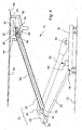
figure 1 is a planar view, partially in cross-section, of a current collector assembly according to a first embodiment of the invention; -
figure 2 is a planar view, partially in cross-section, of a current collector assembly according to a second embodiment of the invention; -
figure 3 is a planar view, partially in cross-section, of a current collector assembly according to a third embodiment of the invention; -
figure 4 is a planar view, partially in cross-section, of a current collector assembly according to a fourth embodiment of the invention. - With reference to
figure 1 , an electriccurrent collector assembly 10 is arranged between a roof of anelectric vehicle 12 and acatenary line 14. Abase frame 16 of the collector assembly is secured to theroof 12 and accommodates a pivot bearing 18 for articulating a frontlower support arm 20, which is articulated at its free end to anupper support arm 22 by means of apivot 24. Theupper support arm 22 comprises amedian portion 26 accommodating thepivot 24, anextension 28 on the one side of thepivot 24 and an elongatetubular section 30 on the other side of thepivot 24. A rearlower support arm 32 is articulated to thebase frame 16 about apivot axis 34 and on theextension 28 about apivot axis 36. - A
collector head 40 is pivotally mounted on an upper free end of theupper support arm 22 about apivot axis 42. Thecollector head 40 resiliently carries carbon strips 44. Theupper support arm 22 receives anelongated slide 46 for accommodating afollower 48, which moves forth and back along arectilinear path 49 defined by theslide 46. A connectingrod 50 is articulated to thefollower 48 about anaxis 52 and on thecollector head 40 about apivot axis 54 that is offset in relation to thepivot 42. Anupper guide bar 60 is articulated to thepivot axis 52 of thefollower 48 and on apivot 62 fixed in relation to the frontlower support arm 20, and offset in relation to thepivot 24. Theupper guide bar 60 is received inside the elongatetubular section 30 of theupper support arm 22. Theupper guide bar 60 is used as transmission means for converting a rotational motion of theupper support arm 22 in relation to the frontlower support arm 20 into a linear motion of thefollower 48. in relation to theupper support arm 22. - As can be readily understood from the description and drawings, all pivots of the assembly have their geometrical pivot axes perpendicular to the plane of the figure, so as to enable a planar movement.
- The
collector assembly 10 is driven by a driving means 66, which is represented schematically, and has an operational range between a fully retracted position, and a preset maximal operating position. The length of the frontlower support arm 20 and of the rearlower support arm 32, the distance between thepivot 18 and thepivot 34, and the distance between thepivot 24 and thepivot 36 are chosen so that, when the assembly is moved from the fully retracted position to the maximal operating position, thepivot axis 42 of the collector head moves along a path that approximates a vertical line. Further, the offset of thepivots rod 50 are chosen so that when the assembly is moved from the fully retracted position to the maximal operating position, thecollector head 42 does not substantially rotate in relation to thebase frame 16. - Clearly, the mechanism described here can only achieve an approximation of a pure translation movement of the collector head in relation to the base frame. However, this approximation is regarded as sufficient when the operational range between the fully retracted position and the maximal operating position is not too large corresponding to a four-bar linkage
- A second embodiment of the invention is shown in
figure 2 . The collector assembly according to the second embodiment of the invention is of similar constitution to that of the first embodiment, so that the same reference signs have been taken to designate identical or similar elements. Thecollector assembly 10 according to the second embodiment differs from the previous one essentially by the fact that the transmission of the rotation motion to the collector head is realized by means of a flexible wire orcable 160, which is tensioned between the frontlower support arm 20 and thetraveler 48. A guidingidler pulley 162 is used to guide thewire 160 inside the elongatetubular section 30 of theupper support arm 22. Atensioning spring 164 ensures that the wire is always tight. - A third embodiment of the invention is shown in
figure 3 . The collector assembly according to the third embodiment is of similar constitution to that of the first embodiment, so that the same reference signs have been taken to designate identical or similar elements. - The
collector assembly 10 according to the third embodiment differs from the previous one essentially by the fact that the rotation motion between the upper support arm and the front lower support arm is transmitted to the collector head by means of ahydraulic circuit 260. Thishydraulic circuit 260 comprises aninput cylinder 262 articulated to the front lower support arm, and anoutput cylinder 264 linked to thetraveler 48, both arms being connected to one another by a pipe orhose 266. - A fourth embodiment of the invention is shown in
figure 4 . The collector assembly according to the fourth embodiment of the invention is of similar constitution to that of the first embodiment, so that the same reference signs have been taken to designate identical or similar elements. Thecollector assembly 10 according to the fourth embodiment differs from the first one essentially by the fact that theupper guide bar 60 is articulated to the rearlower support arm 32 and not to the frontlower support arm 20. The access to theguide bar 60 is made easier for assembly and maintenance. - While preferred embodiments of the invention have been described, it is to be understood by those skilled in the art that the invention is naturally not limited to these embodiments. Many variations are possible.
- The embodiments described provide a path of motion of the collector head in relation to base frame, in which the movement of the rotational axis of the collector head is more or less a vertical motion and the rotation of the collector head in relation to the upper support arm compensates more or less the rotation motion of the support arms, so that the collector head does not substantially rotate in relation to the base frame. In this respect, the rectilinear path of the follower shown in the described embodiments may not be optimal to entirely compensate the rotation of the upper support arm, in particular where the operating range of the assembly is important. In such a case or if for any reason a more accurate rotational positioning of the collector head is required, it is possible to use a curved slide to provide a non-rectilinear path for the follower, so as to minimise the rotation of the collector head in relation to the base frame.
- The slide shown in the drawings points towards the
pivot 42, so that a tangent to therectilinear path 49 cuts the rotation axis of thepivot 42. This arrangement is particularly compact. However, it is also possible to offset the general direction of thepath 49 in relation to thepivot axis 42. - The slide can be replaced by any mechanical guide means that ensure a linear path to the follower. For instance, the follower can be provided with rollers.
- The
pivot 54 can be resiliently attached to thecollector head 40, so as to provide a limited degree of freedom of rotation to the collector head for a given position of the support arms. Alternatively, a limited clearance can be provided between thecollector head 40 and thepivot 54. - The rear lower support arm could be replaced by any other means that ensures that the
pivot axis 42 of the collector head moves along a path that approximates a vertical line. For instance, a cam and chain transmission as disclosed inGB 1,506,855 - The assembly has been described with only one front lower support arm, one rear lower support arm and one upper support arm. This is particularly advantageous for limiting the air drag. In order to provide more stiffness to the assembly, it can be however also be advantageous to provide two upper support arms and/or two front or rear lower support arms. The length of the upper support arm is not necessarily substantially equal to the length of the upper support arm.
- Pivots have been used for articulating the lower support arms to the base frame and for articulating the support arms in relation to one another. However, other articulation means are also possible, which can provide pure rotation movement, for instance about an imaginary axis, or a compound movement composed of rotation and translation.
- The transmission means used between the lower support arm and the collector head, i.e. the
guide bar 60, thewire 160 orhydraulic circuit 260, or any equivalent means, are not necessarily located inside a tubular portion of the upper support arm, in particular if for reasons of maintenance, easy access is required. - The tensioning spring of the second embodiment can be loaded between the traveler and the upper support arm, between the connecting rod and the upper support arm or even between the connecting rod and the collector head. Other arrangements are also possible.
- The hydraulic circuit of the third embodiment is a pure passive circuit. If, however, a source of hydraulic or gas pressure is available on board, an active circuit can be used. In such a case, the input cylinder would be replaced by an input valve, sensible to the angle between the lower and upper support arm. A second valve would be added to the output cylinder to measure the position of the collector head in relation to the upper support arm, and both valves would be used to command the flow of fluid from the pressure source to the output cylinder in function.
- End stops can be added to limit the movement of the assembly within the operational range.
- The collector assembly can be mounted on the vehicle irrespective of the direction of travel of the vehicle.
Claims (11)
- An electric current collector assembly (10) for transmitting electrical energy between an electrical line (14) and a vehicle (12), comprising:- a base frame (16) for mounting on the vehicle,- a first lower support arm (20,32) articulated to the base frame (18),- an upper support arm (22) articulated to the first lower support arm (20, 32),- a current collector head (40) articulated to the upper support arm (22);- a connecting rod (50) articulated to the current collector head, and
characterised in that it further comprises- a guide (46) for guiding a follower (48) in relation to the upper support arm (22) along a path (49), the connecting rod (50) being articulated to the follower (48),- transmission means (60) for converting a rotational motion of the upper support arm (22) in relation to the first lower support arm (20, 32) into a motion of the follower (48) in relation to the upper support arm (22) along the path (49). - The electric current collector assembly (10) of claim 1, wherein the path (49) is a rectilinear path (49).
- The electric current collector assembly (10) of claim 2, wherein to the rectilinear path (49) has a longitudinal axis that crosses an axis (42) of rotation of the current collector head (40) in relation to the upper support arm (22).
- The electric current collector assembly (10) of any one of the forgoing claims, wherein the transmission means comprise a guide bar (60) articulated to the first lower support arm (20, 32) and to the follower (48).
- The electric current collector assembly (10) of claim 4, wherein the upper support arm (22) is articulated to the first lower support arm about a first axis of rotation, and the guide bar (60) is articulated to the first lower support arm (20, 32) about a second axis of rotation which is offset in relation to the first axis of rotation.
- The electric current collector assembly (10) of any one of claims 1 to 3, wherein the transmission means comprise a flexible, non-extendible tension link (160) having one end attached to the follower (48) and another end attached to the first lower support arm (20, 32), and a tensioning means (164).
- The electric current collector assembly (10) of any one of claims 1 to 3, wherein the transmission means comprise a fluid circuit (260), a lower cylinder (262) working between the first lower support arm (20, 32) and the upper support arm (22), and a upper cylinder (264) working between the upper support arm (22) and the follower (48).
- The electric current collector assembly (10) of any one of the forgoing claims, wherein the transmission means are at least partly received inside a tubular section (30) of the upper support arm (22).
- The electric current collector assembly (10) of any one of the forgoing claims, further comprising a coupling means (20, 32) between the upper support arm (22) and the base frame (16), such that the angle of the upper support arm (22) and the first lower support arm (20, 32) is a function of the angle between the first lower support arm (20, 32) and the base frame (16).
- The electric current collector assembly (10) of claim 9, wherein the coupling means comprises a second lower support arm (20, 32) articulated to the base frame (16) and to the upper support arm (22).
- The electric current collector assembly (10) of claim 10, wherein a geometrical axis of rotation of the upper support arm (22) in relation to the second lower support arm (20) is located between a geometrical axis of rotation of the upper support arm (22) in relation to the first support arm (32) and the current collector head (40).
Applications Claiming Priority (2)
| Application Number | Priority Date | Filing Date | Title |
|---|---|---|---|
| GB0320376A GB2405390B (en) | 2003-09-01 | 2003-09-01 | Electric current collector for transmitting electrical energy between an electrical line and a vehicle |
| GB0320376 | 2003-09-01 |
Publications (3)
| Publication Number | Publication Date |
|---|---|
| EP1514722A2 EP1514722A2 (en) | 2005-03-16 |
| EP1514722A3 EP1514722A3 (en) | 2007-12-19 |
| EP1514722B1 true EP1514722B1 (en) | 2014-02-12 |
Family
ID=28686650
Family Applications (1)
| Application Number | Title | Priority Date | Filing Date |
|---|---|---|---|
| EP04020620.3A Expired - Lifetime EP1514722B1 (en) | 2003-09-01 | 2004-08-31 | Electric current collector for transmitting electrical energy between an electrical line and a vehicle |
Country Status (3)
| Country | Link |
|---|---|
| EP (1) | EP1514722B1 (en) |
| ES (1) | ES2461243T3 (en) |
| GB (1) | GB2405390B (en) |
Families Citing this family (3)
| Publication number | Priority date | Publication date | Assignee | Title |
|---|---|---|---|---|
| RU2428327C1 (en) * | 2009-11-30 | 2011-09-10 | Открытое акционерное общество "Всероссийский научно-исследовательский и проектно-конструкторский институт электровозостроения" (ОАО "ВЭлНИИ") | Asymmetric current collector for electric rolling stock |
| JP6563307B2 (en) * | 2015-10-23 | 2019-08-21 | 東日本旅客鉄道株式会社 | Single arm type current collector |
| CN109968988A (en) * | 2019-04-14 | 2019-07-05 | 重庆陈氏清洁服务有限公司 | With the vehicle traveling direction control device and automobile by Electricity Functional |
Family Cites Families (6)
| Publication number | Priority date | Publication date | Assignee | Title |
|---|---|---|---|---|
| JPS56129502A (en) * | 1980-03-14 | 1981-10-09 | Koshin Seikosho:Kk | Pantograph and its incorporating method |
| AT383550B (en) * | 1986-01-20 | 1987-07-10 | Eisenbahntechnische Konstrukti | SEMI-SCISSOR PANTIES |
| FR2648404B1 (en) * | 1989-06-14 | 1991-09-13 | Faiveley Sa | AIR CUSHION PANTOGRAPH |
| JP3372139B2 (en) * | 1995-06-02 | 2003-01-27 | 東洋電機製造株式会社 | Single arm type pantograph |
| JPH10304507A (en) * | 1997-04-25 | 1998-11-13 | Toyo Electric Mfg Co Ltd | Single arm type pantograph |
| FR2813815B1 (en) * | 2000-09-14 | 2003-02-21 | Christian Salesse | HIGH PERFORMANCE FORCE BALANCING DEVICE |
-
2003
- 2003-09-01 GB GB0320376A patent/GB2405390B/en not_active Expired - Fee Related
-
2004
- 2004-08-31 ES ES04020620.3T patent/ES2461243T3/en not_active Expired - Lifetime
- 2004-08-31 EP EP04020620.3A patent/EP1514722B1/en not_active Expired - Lifetime
Also Published As
| Publication number | Publication date |
|---|---|
| GB2405390B (en) | 2006-10-04 |
| EP1514722A3 (en) | 2007-12-19 |
| GB2405390A (en) | 2005-03-02 |
| GB0320376D0 (en) | 2003-10-01 |
| EP1514722A2 (en) | 2005-03-16 |
| ES2461243T3 (en) | 2014-05-19 |
Similar Documents
| Publication | Publication Date | Title |
|---|---|---|
| US7878582B2 (en) | Drive for moving a wind deflector on a cabriolet | |
| CN111660818B (en) | Micro-motion pantograph head | |
| CN108394283B (en) | Novel umbrella-shaped vertically-lifting pantograph body | |
| CN1994784B (en) | Mobile contact network of electrified railway | |
| EP1514722A2 (en) | Electric current collector for transmitting electrical energy between an electrical line and a vehicle | |
| CN113715857B (en) | Front end opening and closing mechanism for railway vehicle | |
| CN112716535A (en) | Rope drives pharynx and wipes away sub-robot | |
| JP2002325305A (en) | Low noise current collector | |
| CN111823871B (en) | Upper part current-collecting device | |
| GB2405391A (en) | Electric current collector for transmitting electrical energy between an electrical line and a vehicle | |
| CN217124523U (en) | Panoramic sunroof glass transmission mechanism | |
| JP4271004B2 (en) | Pantograph device | |
| JP4386253B2 (en) | Pantograph device | |
| CN1321015C (en) | side collector | |
| CN2299300Y (en) | Measuring device for aperture of guide blade of water turbine | |
| CN117921623A (en) | Rail-mounted robot running mechanism and rail-mounted robot running method | |
| CN215056595U (en) | Amusement equipment turnover door | |
| RU2229987C1 (en) | Electric train current collector | |
| CA2353579A1 (en) | Device and method for controlled current collection between a contact wire and a track-bound, electrically operated high speed vehicle | |
| CN101123406B (en) | Sun tracker for solar panel | |
| CN222509244U (en) | Mounting bracket for household photovoltaic use | |
| RU5769U1 (en) | ELECTRIC MOTION COMPOSITION POSITION | |
| CN220680847U (en) | Telescopic device for cleaning robot | |
| JP3938355B2 (en) | Current collector boat equipment for high-speed railway vehicles | |
| RU29503U1 (en) | Current collector of electric train |
Legal Events
| Date | Code | Title | Description |
|---|---|---|---|
| PUAI | Public reference made under article 153(3) epc to a published international application that has entered the european phase |
Free format text: ORIGINAL CODE: 0009012 |
|
| AK | Designated contracting states |
Kind code of ref document: A2 Designated state(s): AT BE BG CH CY CZ DE DK EE ES FI FR GB GR HU IE IT LI LU MC NL PL PT RO SE SI SK TR |
|
| AX | Request for extension of the european patent |
Extension state: AL HR LT LV MK |
|
| PUAL | Search report despatched |
Free format text: ORIGINAL CODE: 0009013 |
|
| AK | Designated contracting states |
Kind code of ref document: A3 Designated state(s): AT BE BG CH CY CZ DE DK EE ES FI FR GB GR HU IE IT LI LU MC NL PL PT RO SE SI SK TR |
|
| AX | Request for extension of the european patent |
Extension state: AL HR LT LV MK |
|
| 17P | Request for examination filed |
Effective date: 20080604 |
|
| AKX | Designation fees paid |
Designated state(s): DE ES FR IT |
|
| 17Q | First examination report despatched |
Effective date: 20090312 |
|
| GRAP | Despatch of communication of intention to grant a patent |
Free format text: ORIGINAL CODE: EPIDOSNIGR1 |
|
| INTG | Intention to grant announced |
Effective date: 20130829 |
|
| GRAS | Grant fee paid |
Free format text: ORIGINAL CODE: EPIDOSNIGR3 |
|
| GRAP | Despatch of communication of intention to grant a patent |
Free format text: ORIGINAL CODE: EPIDOSNIGR1 |
|
| GRAA | (expected) grant |
Free format text: ORIGINAL CODE: 0009210 |
|
| RAP1 | Party data changed (applicant data changed or rights of an application transferred) |
Owner name: BOMBARDIER TRANSPORTATION GMBH |
|
| INTG | Intention to grant announced |
Effective date: 20140102 |
|
| AK | Designated contracting states |
Kind code of ref document: B1 Designated state(s): DE ES FR IT |
|
| REG | Reference to a national code |
Ref country code: DE Ref legal event code: R096 Ref document number: 602004044371 Country of ref document: DE Effective date: 20140320 |
|
| REG | Reference to a national code |
Ref country code: ES Ref legal event code: FG2A Ref document number: 2461243 Country of ref document: ES Kind code of ref document: T3 Effective date: 20140519 |
|
| REG | Reference to a national code |
Ref country code: DE Ref legal event code: R097 Ref document number: 602004044371 Country of ref document: DE |
|
| PLBE | No opposition filed within time limit |
Free format text: ORIGINAL CODE: 0009261 |
|
| STAA | Information on the status of an ep patent application or granted ep patent |
Free format text: STATUS: NO OPPOSITION FILED WITHIN TIME LIMIT |
|
| 26N | No opposition filed |
Effective date: 20141113 |
|
| REG | Reference to a national code |
Ref country code: DE Ref legal event code: R097 Ref document number: 602004044371 Country of ref document: DE Effective date: 20141113 |
|
| REG | Reference to a national code |
Ref country code: FR Ref legal event code: PLFP Year of fee payment: 12 |
|
| PGFP | Annual fee paid to national office [announced via postgrant information from national office to epo] |
Ref country code: ES Payment date: 20150827 Year of fee payment: 12 |
|
| PGFP | Annual fee paid to national office [announced via postgrant information from national office to epo] |
Ref country code: FR Payment date: 20150820 Year of fee payment: 12 |
|
| PGFP | Annual fee paid to national office [announced via postgrant information from national office to epo] |
Ref country code: IT Payment date: 20150824 Year of fee payment: 12 |
|
| REG | Reference to a national code |
Ref country code: DE Ref legal event code: R082 Ref document number: 602004044371 Country of ref document: DE Ref country code: DE Ref legal event code: R081 Ref document number: 602004044371 Country of ref document: DE Owner name: DB SYSTEMTECHNIK GMBH, DE Free format text: FORMER OWNER: BOMBARDIER TRANSPORTATION GMBH, 10785 BERLIN, DE |
|
| REG | Reference to a national code |
Ref country code: FR Ref legal event code: ST Effective date: 20170428 |
|
| PG25 | Lapsed in a contracting state [announced via postgrant information from national office to epo] |
Ref country code: FR Free format text: LAPSE BECAUSE OF NON-PAYMENT OF DUE FEES Effective date: 20160831 |
|
| PG25 | Lapsed in a contracting state [announced via postgrant information from national office to epo] |
Ref country code: IT Free format text: LAPSE BECAUSE OF NON-PAYMENT OF DUE FEES Effective date: 20160831 |
|
| PG25 | Lapsed in a contracting state [announced via postgrant information from national office to epo] |
Ref country code: ES Free format text: LAPSE BECAUSE OF NON-PAYMENT OF DUE FEES Effective date: 20160831 |
|
| REG | Reference to a national code |
Ref country code: ES Ref legal event code: FD2A Effective date: 20181128 |
|
| PG25 | Lapsed in a contracting state [announced via postgrant information from national office to epo] |
Ref country code: ES Free format text: LAPSE BECAUSE OF NON-PAYMENT OF DUE FEES Effective date: 20160901 |
|
| PGFP | Annual fee paid to national office [announced via postgrant information from national office to epo] |
Ref country code: DE Payment date: 20220621 Year of fee payment: 19 |
|
| REG | Reference to a national code |
Ref country code: DE Ref legal event code: R119 Ref document number: 602004044371 Country of ref document: DE |
|
| PG25 | Lapsed in a contracting state [announced via postgrant information from national office to epo] |
Ref country code: DE Free format text: LAPSE BECAUSE OF NON-PAYMENT OF DUE FEES Effective date: 20240301 |