EP1514342B1 - Method and circuit arrangement for operating stepper motors - Google Patents
Method and circuit arrangement for operating stepper motors Download PDFInfo
- Publication number
- EP1514342B1 EP1514342B1 EP03757042A EP03757042A EP1514342B1 EP 1514342 B1 EP1514342 B1 EP 1514342B1 EP 03757042 A EP03757042 A EP 03757042A EP 03757042 A EP03757042 A EP 03757042A EP 1514342 B1 EP1514342 B1 EP 1514342B1
- Authority
- EP
- European Patent Office
- Prior art keywords
- coil
- emk
- measuring
- motor
- current
- Prior art date
- Legal status (The legal status is an assumption and is not a legal conclusion. Google has not performed a legal analysis and makes no representation as to the accuracy of the status listed.)
- Expired - Lifetime
Links
- 238000000034 method Methods 0.000 title claims abstract description 16
- 238000004590 computer program Methods 0.000 claims 2
- 230000001360 synchronised effect Effects 0.000 abstract description 4
- 238000005259 measurement Methods 0.000 description 11
- 230000010363 phase shift Effects 0.000 description 11
- 238000010586 diagram Methods 0.000 description 10
- 238000001514 detection method Methods 0.000 description 5
- 230000007423 decrease Effects 0.000 description 4
- 230000033001 locomotion Effects 0.000 description 3
- 238000012544 monitoring process Methods 0.000 description 3
- 238000004804 winding Methods 0.000 description 3
- 230000001419 dependent effect Effects 0.000 description 2
- 238000013461 design Methods 0.000 description 2
- 238000011161 development Methods 0.000 description 2
- 230000018109 developmental process Effects 0.000 description 2
- 238000011156 evaluation Methods 0.000 description 2
- 230000001133 acceleration Effects 0.000 description 1
- 238000013459 approach Methods 0.000 description 1
- 230000002238 attenuated effect Effects 0.000 description 1
- 230000033228 biological regulation Effects 0.000 description 1
- 230000001276 controlling effect Effects 0.000 description 1
- 230000007613 environmental effect Effects 0.000 description 1
- 230000004907 flux Effects 0.000 description 1
- 230000006698 induction Effects 0.000 description 1
- 230000010354 integration Effects 0.000 description 1
- 230000005415 magnetization Effects 0.000 description 1
- 230000000737 periodic effect Effects 0.000 description 1
- 238000012545 processing Methods 0.000 description 1
- 230000002250 progressing effect Effects 0.000 description 1
- 230000001105 regulatory effect Effects 0.000 description 1
Images
Classifications
-
- H—ELECTRICITY
- H02—GENERATION; CONVERSION OR DISTRIBUTION OF ELECTRIC POWER
- H02P—CONTROL OR REGULATION OF ELECTRIC MOTORS, ELECTRIC GENERATORS OR DYNAMO-ELECTRIC CONVERTERS; CONTROLLING TRANSFORMERS, REACTORS OR CHOKE COILS
- H02P6/00—Arrangements for controlling synchronous motors or other dynamo-electric motors using electronic commutation dependent on the rotor position; Electronic commutators therefor
- H02P6/006—Controlling linear motors
-
- H—ELECTRICITY
- H02—GENERATION; CONVERSION OR DISTRIBUTION OF ELECTRIC POWER
- H02P—CONTROL OR REGULATION OF ELECTRIC MOTORS, ELECTRIC GENERATORS OR DYNAMO-ELECTRIC CONVERTERS; CONTROLLING TRANSFORMERS, REACTORS OR CHOKE COILS
- H02P6/00—Arrangements for controlling synchronous motors or other dynamo-electric motors using electronic commutation dependent on the rotor position; Electronic commutators therefor
- H02P6/14—Electronic commutators
- H02P6/16—Circuit arrangements for detecting position
- H02P6/18—Circuit arrangements for detecting position without separate position detecting elements
- H02P6/182—Circuit arrangements for detecting position without separate position detecting elements using back-emf in windings
-
- H—ELECTRICITY
- H02—GENERATION; CONVERSION OR DISTRIBUTION OF ELECTRIC POWER
- H02P—CONTROL OR REGULATION OF ELECTRIC MOTORS, ELECTRIC GENERATORS OR DYNAMO-ELECTRIC CONVERTERS; CONTROLLING TRANSFORMERS, REACTORS OR CHOKE COILS
- H02P8/00—Arrangements for controlling dynamo-electric motors rotating step by step
- H02P8/32—Reducing overshoot or oscillation, e.g. damping
Definitions
- the invention relates to a method and a circuit arrangement for operating stepper motors or other suitably dimensioned synchronous motors.
- Stepper motors are known to be precisely controlled to move and position controlled.
- the rotational position of a magnetic rotor follows a magnetic field which is generated by phase-shifted energization of a plurality of coils which are arranged around the rotor. If a stepper motor is to serve not only for the relative, but also for the absolute positioning of an object, it is first necessary to determine a reference position to which the absolute position can be referred. A controlled absolute positioning is then possible as long as the control of the stepping motor takes place taking into account its characteristic motion parameters such as rotation angle, speed and acceleration.
- a reference position essentially two alternatives are known. These are on the one hand, the mechanical homing, in which the motor is driven against a mechanical, serving as a reference position limit or stop, and on the other the electrical reference travel, in which a sensor (for example, an electromechanical switch or a photoelectric sensor) upon reaching a Reference position generates a corresponding signal.
- a sensor for example, an electromechanical switch or a photoelectric sensor
- step losses may occur due to certain operating states such as suddenly occurring load changes due to obstacles or the like during operation of a stepper motor, or the stepper motor may even stop, so that a new reference run becomes necessary.
- a reference run during operation is not possible, so that in addition to the single determination of the reference position, a monitoring of the operating state of the stepping motor during operation - but especially without additional sensors - is desirable.
- a method of driving rotary detector circuitry which determines whether a drive pulse being fed to a stepper motor causes the rotor to rotate in the correct direction.
- the rotation detection essentially takes place in that an element of high or low impedance is electrically connected to a winding of the motor when a first or second switching device is being retracted and that first, second and third signals are fed to the first and second switching device in order to feed the element to separate low impedance from the winding while the high impedance element is connected to the winding at the time of rotation detection.
- a method for controlling a voltage / frequency converter controlled single or polyphase electric motor is known, with which a phase shift between an EMF voltage and a BEMF voltage is determined from the deviation between the zero crossing of the phase current and the voltage generated by self-induction and the frequency the converter is readjusted accordingly.
- the measurement of the self-induction takes place at the zero crossing of the current profile of the associated phase, during which the phase is disconnected from the supply network.
- the invention is based on the general object to provide a method and a circuit arrangement for operating a stepping motor (or another suitably dimensioned synchronous motor), with the / in a simple way, a load detection and thus a determination of a reference position of the motor is possible.
- This object is achieved according to claim 1 with a method for operating stepper motors with a first mode for a normal engine operation, in which an alternating current is impressed in at least one of the coils of the stepping motor, and a second mode for determining a reference position of the stepping motor based on a by driving the stepping motor against a mechanical stop caused increase in load, by comparing the height of a current flowing in the coil measuring current with at least a lower threshold, wherein the height of the measuring current is determined essentially by the phase of a by a rotor of the motor in the coil against induced voltage, and wherein the reference position is defined when the measurement current becomes less than the lower threshold, and wherein the second mode for the coil is activated within a time window of the first mode either by shorting the coil when the AC current impressed in the coil approaches a zero crossing, or the direction of the AC current injected into the coil is reversed.
- the object is further achieved by a circuit arrangement for operating a stepping motor according to claim 6.
- a general advantage of these solutions is that no sensors are required and a relatively simple and inexpensive implementation is possible, especially when the motor is driven by pulse width modulation (PWM) of a voltage that impresses a corresponding current in the motor coils (coil current) the components required for evaluating the measuring current (short-circuit current) are already largely present in a PWM circuit.
- PWM pulse width modulation
- the background is the fact that with increasing motor load and thus increasing load angle (angle between the rotor and the main direction of the magnetic field generated by the coils), the phase shift between the coil current impressed into the coil and the voltage counteracted by the rotor becomes smaller (and at standing engine is zero).
- the magnitude of the measuring current (current lobe) at constant speed directly represents the magnitude of the torque of the engine load and, together with the torque characteristic of the engine concerned indirectly the load angle.
- a reference position of the motor can be detected sensorless.
- the disadvantages associated with a conventional sensorless determination of a reference position such as mechanical wear and noise development, do not occur or only to a significantly lesser extent.
- An advantage of the above-described almost direct load or torque measurement in the (mechanical) reference run is that it is largely independent of the modulus of elasticity of the mechanical stop.
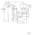
- Figure 1 shows a schematic diagram of a circuit arrangement, which can be switched with a switch S between a first mode for normal engine operation (switch position 1) and a second mode for detecting an operating condition and in particular a reference position of the engine (switch position 0) by measuring a mechanical load change is determined when driving the stepper motor against a mechanical stop.
- the stepping motor itself is shown only in the form of one of its coils L with a serial internal resistance R L , a plurality of these coils being arranged in a known manner in a circle around a magnetic rotor. Alternatively, however, it may also be a linear stepper motor.
- a voltage source for generating a supply voltage U M (PWM voltage) connected to the in the first mode a specific target current (coil current) I L in the (b) coil ( n) L is impressed.
- a measuring resistor R S In series with each coil L is also a measuring resistor R S , at which a measuring voltage U S in dependence on an actually flowing through the coil L (measuring) current drops.
- such a stepper motor driver operates at a sufficiently high supply voltage as a quasi-ideal power source, provided that the power reduction takes place not only passive (“slow decay”), but active (“fast decay”).
- the circuit arrangement further comprises a measuring circuit M, at the input of which the measuring voltage U S is present and which has a comparator K for comparing the measuring voltage U S with a reference voltage U R , and a digital / analog converter DAC for generating the comparison voltage from one of the measuring circuit M digital signal.
- the comparison voltage U R can also be supplied in a different manner or in analog form.
- control circuit C which generates the digital signal for the digital / analog converter DAC and the output signal of the comparator K is supplied.
- the control circuit C can be controlled via an interface I in order to switch the switch S between its two switch positions 0 and 1 as a function of the output signal of the comparator K or to provide this output signal for further processing.
- the measuring circuit M and the control circuit C are in the case of a pulse width modulation (PWM) controlled coil current I L in general already present, so that the circuit arrangement according to the invention can be implemented inexpensively and with relatively little additional effort.
- PWM pulse width modulation
- the coils L are phase-shifted with alternating currents fed so that in a known manner, a magnetic field is progressing, the magnetic rotor follows stepwise or quasi-continuously in microsteps.
- the measuring voltage U S dropped across the measuring resistor R S can be evaluated and used in a known manner to control or regulate the voltage source generating the supply voltage U M.
- an electric voltage U EMK is induced in the coil L, counteracting the supply voltage U M and with respect to its course substantially relative to the speed of the rotor and its instantaneous position the coil is dependent.
- this voltage is represented by a voltage source connected in series with the coil L, which generates the voltage U EMK .
- the voltage U L over the terminals of the coil L with respect to the impressed coil current I L is phase-shifted by 90 ° (ie at an active power of zero). The average power over a period is then equal to zero. With increasing load angle, this phase shift between the voltage U L and the coil current decreases I L. At maximum load angle (ie, just before a step loss), the phase shift is ultimately essentially zero and the power is maximum.
- the counter-induced voltages U EMK are ideally also sinusoidal and cosinusoidal and opposite the coil currents I L in the respective coils L by 90 ° in phase postponed.
- phase shifts of a constant nature and other characteristics of the voltages U EMK can be caused by the design of the motor and in particular the geometric shape of the rotor and the stator and their magnetization.
- stepper motor may jump one or more integer multiples of the current period (four full steps in a 2-phase stepper motor) and thus lose steps.
- a phase shift also occurs between the coil current I L and the counter-induced voltage U EMK , whereby the course of the voltage U EMK can also change considerably due to the jumps.
- the phase of the counter-induced voltage U EMK thus essentially represents the rotor position.
- the time course of the target current I L through the coils L is not necessarily sinusoidal and cosinusoidal. Depending on the type of stepper motor, better running behavior can be achieved with trapezoidal or triangular current patterns or hybrid forms thereof.
- the counter-induced voltage U EMK is in principle nevertheless suitable for determining the above-described movement and load states of the stepping motor, ie its operating state, and thus also for detecting a mechanical stop, for example at a reference position. since the height of the voltage U EMK and the phase position to the coil current I L in addition to the speed of the rotor in particular depends on the load angle of the rotor and thus the load condition of the motor.
- the amplitude of the counter-induced voltage U EMK is proportional to the speed of the rotor.
- the phase of this voltage U EMK relative to the impressed coil current I L is essentially determined by the mechanical load. At a maximum possible load, this phase shift decreases substantially to the value 0. This is clear from Figures 2 to 4 and will be explained in more detail later.
- the voltage U EMK could be measured with a non-energized coil L directly above the terminals of the coil. However, since such a coil L makes no contribution to the torque of the motor, this type of detection is not desirable. Also, a quick change between energized and non-energized state is not desirable due to the occurring, relatively high induction voltages.
- the counter-induced voltage U EMK in the second operating mode is determined by disconnecting the coil from the supply voltage U M and short-circuiting the coil, in each case periodically within such time windows in which the impressed current I L in the relevant coil L relatively low is, that is shortly before and after the polarity change of this current or the supply voltage U M impressing on it .
- the switch S is switched to the switch position 0.
- the beginning of the time window need not be determined by monitoring the measurement voltage U S and comparison with a comparison voltage. Rather, the beginning and the length of the time window is given by the known or fixed profile of the supply voltage U M or the course of the injected into the coil in question I L , so that the control circuit C for switching the switch S directly via the interface I can be controlled accordingly.
- the counter-induced voltage U EMK drives in the thus shorted coil circuit now a measuring current I S, EMK (current lobe), which generates a corresponding voltage drop U S, EMK on the measuring resistor R S.
- This voltage U S, EMK is in turn evaluated by the measuring circuit M to determine the operating condition of the motor and to determine whether the motor is running under a more or less high mechanical load or even against a mechanical stop, to avoid wear if necessary switch off immediately.
- the voltage U S, EMK in the comparator K is compared with different threshold values U SO , U SU , which are determined as a function of the rotational speed of the motor and as digital values via the interface I and the control circuit C to the digital / analog converter DAC (or also analog) are supplied.
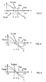
- the vertical axis denotes the height of the current or the voltage, while the period is plotted on the horizontal axis.
- This coil current I L is within the time window Z, in which the coil circuit is shorted by switching the switch S in the switch position 0, zero. Instead, flows within the time window Z substantially caused by the counter-induced voltage U EMK measuring current I S, EMK (shown in dashed lines, current lobes), through which a measuring voltage U S, EMK decreases at the measuring resistor R S.
- FIG. 2 shows the courses of these currents and voltages for a substantially unloaded state, that is to say at a minimum load angle
- FIG. 3 shows the courses at an average load and a mean load angle
- FIG. 4 shows the curves of the currents and voltages at a maximum load and a maximum load angle.
- phase shift decreases with increasing load between the coil current I L or - during the second mode - between the measuring current I S, EMK through the coil L and the counter-induced voltage U EMK .
- the counter-induced voltage U EMK behaves in phase opposition to the supply voltage U M with respect to its polarity.
- the magnitude of the measuring current I S, EMF (current lobe) flowing within the time window Z and thus the height of the measuring voltage U S, EMK generated by the latter within the time window Z depends on the rotational speed and the load angle of the motor caused by a load and thus represents also the recorded active power.
- a load change leads to a phase shift of the counter-induced voltage U EMK and thus to a change in the current driven by this in the coil circuit current. This change in turn results in a change of the measuring current I S, EMF (current lobe) flowing within the time window Z, which is detected by evaluation of the measuring voltage U S, EMK .
- a change in the load of the motor can be detected.
- Load changes are preferably detected by a comparison of the measuring voltage U S, EMK within the time window Z with threshold values, which are determined as a function of the speed of the motor.
- an upper and a lower threshold value U SO , U SU for the measuring voltage U S, EMK are set such that the measuring voltage U S, EMK is greater at a certain speed and relatively low load of the motor , as the upper threshold U SO , while at a mechanical load increase, which is caused by driving against a mechanical stop, the measuring voltage U S, EMK is below the lower threshold U SU .
- Figure 2 shows the case in which within the time window Z, a measuring current I S, EMK flows through the coil, through which a measuring voltage U S, EMK is generated, which corresponds to the upper threshold U SO .
- a measuring current I S, EMF flows through the coil, through which a measuring voltage U S, EMK which corresponds to the lower threshold value U SU drops.
- the load is so great that the measuring current I S, EMF and thus also the voltage drop U S, EMK is substantially zero.
- the measurement voltage U S, EMK is thus compared with the two threshold values U SO , U SU within a time window Z, the measurement voltage being applied to one input of the comparator K and one threshold value to the other input of the comparator K.
- the threshold values U SO , U SU are supplied via the interface I and the control circuit C to the digital / analog converter DAC.
- the internal resistance R L of the relevant coil L is of the order of the measuring resistor R S , so that the measuring voltage U S, EMK in the load measurement sufficiently large, that is in the range of the measuring voltage U S. in normal operation. If a switchable measuring resistor R S is provided, the solution according to the invention can also be applied to high-impedance motors. If, on the other hand, R L >> R S is, then the measuring circuit M should have a sufficiently high gain.
- the measuring voltage U S, EMK is independent of the supply voltage U M , since it is detected during a time window in which the supply voltage (PWM) is not present.
- the current loop resulting from the short-circuiting of the coil circuit is low-resistance, so that the measuring voltage U S, EMK is relatively insensitive to interference.
- the measuring resistor R S causes a current limitation with a short-circuited coil circuit.
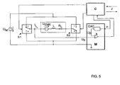
- FIG. 5 shows a block diagram of a second circuit arrangement according to the invention, in which the same or corresponding components as in FIG. 1 are provided with the same designations.
- the PWM supply voltage U M can be reversed by means of a first and a second switch S1, S2, which are switched by the control circuit C.
- the second operating mode during which the measured current I S, EMK generated by the region-induced voltage U EMK is detected and evaluated according to the above explanation, in this case becomes immediately after the polarity reversal of the PWM supply voltage, ie immediately after the switching of the two switches S1 , S2 activated, whereby previously the measuring current must not be regulated out (slow-decay mode).
- the measuring voltage conducted to the comparator does not necessarily have to be generated by a voltage drop by means of a resistor R S. Rather, it is also possible to use Hall sensors, current dividers in MOSFET switches or other elements, if appropriate at other locations of the circuit arrangement, with which a signal proportional to the measuring current through the coil L is generated, which signal corresponds to the corresponding signal Thresholds can be compared.
- phase shift and the amplitude reduction of the periodic coil current I L are very sensitive to a load change, but both sizes are very insensitive to other disturbances that are not related to it, such as the irradiation of electrical energy. As a result, a very accurate detection of even small load changes is possible.
- the coil in the coil circuit smoothes any electrical interference, so that their influence is further reduced.
- the measurement conditions are very well defined within the time window Z and thus very well reproducible.
- the current I S, EMK flowing within the time window Z only depends on the rotational speed of the motor, the load angle and motor constants, but does not or only very slightly depends on parameters that drift or vary due to specimen scattering.
- inventive method and the circuit arrangement according to the invention is also suitable for use with other synchronous motors, provided that they are dimensioned such that at least one of the coil circuits can be short-circuited.
Landscapes
- Engineering & Computer Science (AREA)
- Power Engineering (AREA)
- Control Of Stepping Motors (AREA)
Abstract
Description
Die Erfindung betrifft ein Verfahren und eine Schaltungsanordnung zum Betreiben von Schrittmotoren oder anderen geeignet dimensionierten Synchronmotoren.The invention relates to a method and a circuit arrangement for operating stepper motors or other suitably dimensioned synchronous motors.
Schrittmotoren lassen sich bekanntlich präzise gesteuert bewegen und gesteuert positionieren. Die Drehstellung eines magnetischen Rotors folgt dabei einem magnetischen Feld, das durch phasenverschobene Bestromung einer Mehrzahl von Spulen erzeugt wird, die um den Rotor angeordnet sind. Wenn ein Schrittmotor nicht nur zur relativen, sondern auch zur absoluten Positionierung eines Gegenstandes dienen soll, so ist zunächst eine Referenzposition zu bestimmen, auf die die absolute Position bezogen werden kann. Eine gesteuerte absolute Positionierung ist dann solange möglich, wie die Steuerung des Schrittmotors unter Berücksichtigung seiner charakteristischen Bewegungsparameter wie Drehwinkel, Geschwindigkeit und Beschleunigung erfolgt.Stepper motors are known to be precisely controlled to move and position controlled. The rotational position of a magnetic rotor follows a magnetic field which is generated by phase-shifted energization of a plurality of coils which are arranged around the rotor. If a stepper motor is to serve not only for the relative, but also for the absolute positioning of an object, it is first necessary to determine a reference position to which the absolute position can be referred. A controlled absolute positioning is then possible as long as the control of the stepping motor takes place taking into account its characteristic motion parameters such as rotation angle, speed and acceleration.
Zur Bestimmung einer Referenzposition sind im wesentlichen zwei Alternativen bekannt. Dies sind zum einen die mechanische Referenzfahrt, bei der der Motor gegen eine mechanische, als Referenzposition dienende Begrenzung oder einen Anschlag gefahren wird, und zum anderen die elektrische Referenzfahrt, bei der ein Sensor (zum Beispiel ein elektromechanischer Schalter oder eine Lichtschranke) beim Erreichen einer Referenzposition ein entsprechendes Signal erzeugt.To determine a reference position essentially two alternatives are known. These are on the one hand, the mechanical homing, in which the motor is driven against a mechanical, serving as a reference position limit or stop, and on the other the electrical reference travel, in which a sensor (for example, an electromechanical switch or a photoelectric sensor) upon reaching a Reference position generates a corresponding signal.
Beide Alternativen haben Vor- und Nachteile. Während bei der mechanischen Referenzfahrt mit Geräuschentwicklung und einem erhöhten Verschleiß durch die mechanische Belastung zu rechnen ist, ist die Realisierung der elektrischen Referenzfahrt aufgrund der Sensoren mit höheren Kosten, einem erhöhten konstruktiven Aufwand für die Integration der Sensoren in ein mechatronisches System sowie mit zusätzlichem Verkabelungsaufwand verbunden, wobei insbesondere unter rauhen Umgebungsbedingungen auch die Zuverlässigkeit der Sensoren selbst ein Problem darstellen kann.Both alternatives have advantages and disadvantages. While in the mechanical homing with noise and increased wear due to the mechanical stress is expected, the realization of the electrical reference travel due to the sensors with higher costs, increased design effort for integration of the sensors in a mechatronic system and additional cabling In particular, under harsh environmental conditions, the reliability of the sensors themselves can be a problem.
Weiterhin ist zu berücksichtigen, dass durch bestimmte Betriebszustände wie plötzlich auftretende Lastwechsel durch Hindernisse o. ä. im laufenden Betrieb eines Schrittmotors Schrittverluste auftreten können oder der Schrittmotor sogar stehen bleibt, so dass eine erneute Referenzfahrt notwendig wird. Es gibt jedoch Anwendungen, bei denen eine Referenzfahrt im laufenden Betrieb nicht möglich ist, so dass neben der einmaligen Bestimmung der Referenzposition auch eine Überwachung des Betriebszustandes des Schrittmotors im laufenden Betrieb - insbesondere jedoch ohne zusätzliche Sensoren - wünschenswert ist.Furthermore, it must be taken into account that step losses may occur due to certain operating states such as suddenly occurring load changes due to obstacles or the like during operation of a stepper motor, or the stepper motor may even stop, so that a new reference run becomes necessary. However, there are applications in which a reference run during operation is not possible, so that in addition to the single determination of the reference position, a monitoring of the operating state of the stepping motor during operation - but especially without additional sensors - is desirable.
Aus der
Aus der
Der Erfindung liegt demgegenüber die allgemeine Aufgabe zugrunde, ein Verfahren und eine Schaltungsanordnung zum Betreiben eines Schrittmotors (oder eines anderen geeignet dimensionierten Synchronmotors) zu schaffen, mit dem / der in einfacher Weise eine Lasterkennung und damit auch eine Ermittlung einer Referenzposition des Motors möglich ist.The invention is based on the general object to provide a method and a circuit arrangement for operating a stepping motor (or another suitably dimensioned synchronous motor), with the / in a simple way, a load detection and thus a determination of a reference position of the motor is possible.
Gelöst wird diese Aufgabe gemäß Anspruch 1 mit Verfahren zum Betreiben von Schrittmotoren mit einer ersten Betriebsart für einen normalen Motorbetrieb, in dem ein Wechselstrom in mindestens eine der Spulen des Schrittmotors eingeprägt wird, sowie einer zweiten Betriebsart zur Ermittlung einer Referenzposition des Schrittmotors anhand einer durch Fahren des Schrittmotors gegen einen mechanischen Anschlag verursachten Lasterhöhung, durch Vergleichen der Höhe eines in der Spule fließenden Messstroms mit mindestens einem unteren Schwellwert, wobei die Höhe des Messstroms im wesentlichen durch die Phase einer durch einen Rotor des Motors in der Spule gegeninduzierte Spannung bestimmt wird, und wobei die Referenzposition festgelegt bzw. definiert wird, wenn der Messstrom kleiner als der untere Schwellwert wird, und wobei die zweite Betriebsart für die Spule innerhalb eines Zeitfensters der ersten Betriebsart entweder dadurch aktiviert wird, dass die Spule kurzgeschlossen wird, wenn sich der in die Spule eingeprägte Wechselstrom an einen Nulldurchgang annähert, oder die Richtung des in die Spule eingeprägten Wechselstroms umgekehrt wird.This object is achieved according to
Die Aufgabe wird ferner mit einer Schaltungsanordnung zum Betreiben eines Schrittmotors gemäß Anspruch 6 gelöst.The object is further achieved by a circuit arrangement for operating a stepping motor according to claim 6.
Ein allgemeiner Vorteil dieser Lösungen besteht darin, dass keine Sensoren erforderlich sind und eine relativ einfache und kostengünstige Realisierung möglich ist, insbesondere wenn der Motor durch Pulsweitenmodulation (PWM) einer Spannung angesteuert wird, die einen entsprechenden Strom in die Motorspulen (Spulenstrom) einprägt, da die zur Auswertung des Messstroms (Kurzschlussstrom) erforderlichen Komponenten in einer PWM-Schaltung bereits weitgehend vorhanden sind.A general advantage of these solutions is that no sensors are required and a relatively simple and inexpensive implementation is possible, especially when the motor is driven by pulse width modulation (PWM) of a voltage that impresses a corresponding current in the motor coils (coil current) the components required for evaluating the measuring current (short-circuit current) are already largely present in a PWM circuit.
Ein weiterer Vorteil dieser Lösung besteht darin, dass der Beginn des Messstroms (Stromzipfels) aufgrund der Regelung des Spulenstroms (Zielstrom) durch die PWM-Spannung sehr gut reproduzierbar und weitgehend unabhängig von der Höhe dieser Spannung ist. Dadurch ergibt sich eine zumindest weitergehende Unabhängigkeit von Bauteiletoleranzen.Another advantage of this solution is that the start of the measuring current (current lobe) due to the control of the coil current (target current) by the PWM voltage is very well reproducible and largely independent of the magnitude of this voltage. This results in at least further independence of component tolerances.
Ferner hat sich gezeigt, dass ein zumindest weitgehend linearer Zusammenhang zwischen der Höhe des Messstroms und der durch eine mechanische Last entzogenen Leistung besteht. Dies bedeutet insbesondere, dass der Messstrom um so kleiner wird, je höher die mechanische Last an dem Motor ist.Furthermore, it has been shown that there is an at least largely linear relationship between the magnitude of the measuring current and the power removed by a mechanical load. This means in particular that the measuring current is the same becomes smaller, the higher the mechanical load on the engine.
Hintergrund ist die Tatsache, dass mit steigender Motorlast und damit steigendem Lastwinkel (Winkel zwischen dem Rotor und der Hauptrichtung des von den Spulen erzeugten magnetischen Feldes) die Phasenverschiebung zwischen dem in die Spule eingeprägten Spulenstrom und der durch den Rotor gegeninduzierten Spannung kleiner wird (und bei stehendem Motor Null ist).The background is the fact that with increasing motor load and thus increasing load angle (angle between the rotor and the main direction of the magnetic field generated by the coils), the phase shift between the coil current impressed into the coil and the voltage counteracted by the rotor becomes smaller (and at standing engine is zero).
Da die mechanische Leistung des Motors bei konstanter Geschwindigkeit proportional zu der Motorkraft bzw. dem Motordrehmoment ist, stellt die Höhe des Messstroms (Stromzipfel) bei konstanter Geschwindigkeit direkt die Höhe des Drehmomentes der Motorlast und zusammen mit der Drehmomentcharakteristik des betreffenden Motors indirekt den Lastwinkel dar.Since the mechanical power of the engine at constant speed is proportional to the engine power or the engine torque, the magnitude of the measuring current (current lobe) at constant speed directly represents the magnitude of the torque of the engine load and, together with the torque characteristic of the engine concerned indirectly the load angle.
Insbesondere kann durch Fahren des Motors gegen einen mechanischen Anschlag und den dadurch veränderten Betriebs- bzw. Lastzustand auch eine Referenzposition des Motors sensorlos erkannt werden. Die mit einer üblichen sensorlosen Bestimmung einer Referenzposition verbundenen Nachteile wie mechanischer Verschleiß und Geräuschentwicklung treten dabei nicht oder in nur wesentlich geringerem Maße in Erscheinung.In particular, by driving the motor against a mechanical stop and the thereby changed operating or load state, a reference position of the motor can be detected sensorless. The disadvantages associated with a conventional sensorless determination of a reference position, such as mechanical wear and noise development, do not occur or only to a significantly lesser extent.
Ein Vorteil der oben erläuterten nahezu direkten Last- bzw. Drehmomentmessung besteht bei der (mechanischen) Referenzfahrt darin, dass diese weitgehend unabhängig von dem Elastizitätsmodul des mechanischen Anschlags ist.An advantage of the above-described almost direct load or torque measurement in the (mechanical) reference run is that it is largely independent of the modulus of elasticity of the mechanical stop.
Die Unteransprüche haben vorteilhafte Weiterbildungen der Erfindung zum Inhalt.The dependent claims have advantageous developments of the invention to the content.
Weitere Einzelheiten, Merkmale und Vorteile der Erfindung ergeben sich aus der folgenden Beschreibung einer bevorzugten Ausführungsform anhand der Zeichnungen. Es zeigt:
- Fig. 1
- ein Prinzipschaltbild einer ersten erfindungsgemäßen Schaltungsanordnung;
- Fig. 2
- ein erstes Diagramm der Spannungs- und Stromverläufe im Bereich eines Nulldurchgangs des Spulenstroms;
- Fig. 3
- ein zweites Diagramm der Spannungs- und Stromverläufe im Bereich eines Nulldurchgangs des Spulenstroms;
- Fig. 4
- ein drittes Diagramm der Spannungs- und Stromverläufe im Bereich eines Nulldurchgangs des Spulenstroms; und
- Fig. 5
- ein Prinzipschaltbild einer zweiten erfindungsgemäßen Schaltungsanordnung.
- Fig. 1
- a schematic diagram of a first circuit arrangement according to the invention;
- Fig. 2
- a first diagram of the voltage and current waveforms in the region of a zero crossing of the coil current;
- Fig. 3
- a second diagram of the voltage and current waveforms in the area a zero crossing of the coil current;
- Fig. 4
- a third diagram of the voltage and current waveforms in the range of a zero crossing of the coil current; and
- Fig. 5
- a schematic diagram of a second circuit arrangement according to the invention.
Figur 1 zeigt ein Prinzipschaltbild einer Schaltungsanordnung, die mit einem Schalter S zwischen einer ersten Betriebsart für einen normalen Motorbetrieb (Schalterstellung 1) und einer zweiten Betriebsart zur Erfassung eines Betriebszustandes und insbesondere einer Referenzposition des Motors (Schalterstellung 0) umgeschaltet werden kann, die durch Messung einer mechanischen Lastveränderung beim Fahren des Schrittmotors gegen einen mechanischen Anschlag ermittelt wird.Figure 1 shows a schematic diagram of a circuit arrangement, which can be switched with a switch S between a first mode for normal engine operation (switch position 1) and a second mode for detecting an operating condition and in particular a reference position of the engine (switch position 0) by measuring a mechanical load change is determined when driving the stepper motor against a mechanical stop.
Der Schrittmotor selbst ist nur in Form einer seiner Spulen L mit einem seriellen Innenwiderstand RL dargestellt, wobei eine Mehrzahl dieser Spulen in bekannter Weise kreisförmig um einen magnetischen Rotor angeordnet ist. Alternativ dazu kann es sich jedoch auch um einen Linear-Schrittmotor handeln.The stepping motor itself is shown only in the form of one of its coils L with a serial internal resistance R L , a plurality of these coils being arranged in a known manner in a circle around a magnetic rotor. Alternatively, however, it may also be a linear stepper motor.
Parallel zu der Spule L (oder einander zugeordneten Spulengruppen) ist jeweils eine Spannungsquelle zur Erzeugung einer Versorgungsspannung UM (PWM-Spannung) geschaltet, mit der in der ersten Betriebsart ein bestimmter Zielstrom (Spulenstrom) IL in die betreffende(n) Spule(n) L eingeprägt wird. In Serie zu jeder Spule L liegt ferner ein Messwiderstand RS, an dem eine Messspannung US in Abhängigkeit von einem tatsächlich durch die Spule L fließenden (Mess-) Strom abfällt.In parallel to the coil L (or coil groups associated with each other) is in each case a voltage source for generating a supply voltage U M (PWM voltage) connected to the in the first mode, a specific target current (coil current) I L in the (b) coil ( n) L is impressed. In series with each coil L is also a measuring resistor R S , at which a measuring voltage U S in dependence on an actually flowing through the coil L (measuring) current drops.
Im Idealfall arbeitet ein solcher Schrittmotortreiber bei hinreichend hoher Versorgungsspannung als quasi ideale Stromquelle, sofern der Stromabbau nicht nur passiv ("Slow Decay"), sondern aktiv ("Fast Decay") stattfindet.Ideally, such a stepper motor driver operates at a sufficiently high supply voltage as a quasi-ideal power source, provided that the power reduction takes place not only passive ("slow decay"), but active ("fast decay").
Die Schaltungsanordnung umfasst weiterhin eine Messschaltung M, an deren Eingang die Messspannung US anliegt und die einen Komparator K zum Vergleichen der Messspannung US mit einer Vergleichsspannung UR aufweist, sowie einen Digital/Analogwandler DAC zum Erzeugen der Vergleichsspannung aus einem der Messschaltung M zugeführten digitalen Signal. Die Vergleichsspannung UR kann auch in anderer Weise oder in analoger Form zugeführt werden.The circuit arrangement further comprises a measuring circuit M, at the input of which the measuring voltage U S is present and which has a comparator K for comparing the measuring voltage U S with a reference voltage U R , and a digital / analog converter DAC for generating the comparison voltage from one of the measuring circuit M digital signal. The comparison voltage U R can also be supplied in a different manner or in analog form.
Weiterhin ist eine Steuerschaltung C vorgesehen, die das digitale Signal für den Digital/Analogwandler DAC erzeugt und der das Ausgangssignal des Komparators K zugeführt wird. Die Steuerschaltung C kann über ein Interface I angesteuert werden, um in Abhängigkeit von dem Ausgangssignal des Komparators K den Schalter S zwischen seinen beiden Schalterstellungen 0 und 1 umzuschalten beziehungsweise dieses Ausgangssignal einer weiteren Verarbeitung zur Verfügung zu stellen.Furthermore, a control circuit C is provided which generates the digital signal for the digital / analog converter DAC and the output signal of the comparator K is supplied. The control circuit C can be controlled via an interface I in order to switch the switch S between its two
Die Messschaltung M sowie die Steuerschaltung C sind im Falle eines durch Pulsweitenmodulation (PWM) gesteuerten Spulenstroms IL im allgemeinen bereits vorhanden, so dass sich die erfindungsgemäße Schaltungsanordnung kostengünstig und mit relativ geringem Zusatzaufwand realisieren lässt.The measuring circuit M and the control circuit C are in the case of a pulse width modulation (PWM) controlled coil current I L in general already present, so that the circuit arrangement according to the invention can be implemented inexpensively and with relatively little additional effort.
Im normalen Motorbetrieb (erste Betriebsart) werden in der Schalterstellung 1 die Spulen L phasenverschoben mit Wechselströmen so gespeist, dass in bekannter Weise ein fortschreitendes Magnetfeld entsteht, dem der magnetische Rotor schrittweise oder quasi-kontinuierlich in Mikroschritten folgt.In normal engine operation (first mode), in the
Um einen definierten Zielstrom IL in die Spule L einzuprägen (Spulenstrom), kann die an dem Messwiderstand RS abfallende Messspannung US ausgewertet und in bekannter Weise zur Steuerung bzw. Regelung der die Versorgungsspannung UM erzeugenden Spannungsquelle verwendet werden.In order to impress a defined target current I L in the coil L (coil current), the measuring voltage U S dropped across the measuring resistor R S can be evaluated and used in a known manner to control or regulate the voltage source generating the supply voltage U M.
Durch die Bewegung des Rotors und die dadurch verursachte magnetische Flussänderung wird in der Spule L eine elektrische Spannung UEMK (gegen-) induziert, die der Versorgungsspannung UM entgegenwirkt und hinsichtlich ihres Verlaufes im wesentlichen von der Geschwindigkeit des Rotors und dessen momentaner Position relativ zu der Spule abhängig ist. Im Schaltbild der Figur 1 ist diese Spannung durch eine in Serie zu der Spule L geschaltete Spannungsquelle dargestellt, die die Spannung UEMK erzeugt.As a result of the movement of the rotor and the magnetic flux change caused thereby, an electric voltage U EMK is induced in the coil L, counteracting the supply voltage U M and with respect to its course substantially relative to the speed of the rotor and its instantaneous position the coil is dependent. In the diagram of Figure 1, this voltage is represented by a voltage source connected in series with the coil L, which generates the voltage U EMK .
Ohne mechanische Last (das heißt bei einem Lastwinkel von im wesentlichen 0° und einem idealisierten Innenwiderstand RL der Spule von 0 Ohm) ist die Spannung UL über den Klemmen der Spule L gegenüber dem eingeprägten Spulenstrom IL um 90° phasenverschoben (d. h. bei einer Wirkleistung von Null). Die über eine Periode gemittelte elektrische Leistung ist dann gleich Null. Mit steigendem Lastwinkel vermindert sich diese Phasenverschiebung zwischen der Spannung UL und dem Spulenstrom IL. Bei maximalem Lastwinkel (das heißt kurz vor einem Schrittverlust) ist die Phasenverschiebung schließlich im wesentlichen Null und die Leistung ist maximal.Without mechanical load (that is, at a load angle of substantially 0 ° and an idealized internal resistance R L of the coil of 0 ohms), the voltage U L over the terminals of the coil L with respect to the impressed coil current I L is phase-shifted by 90 ° (ie at an active power of zero). The average power over a period is then equal to zero. With increasing load angle, this phase shift between the voltage U L and the coil current decreases I L. At maximum load angle (ie, just before a step loss), the phase shift is ultimately essentially zero and the power is maximum.
Bei einem mechanisch unbelasteten Schrittmotor, der mit sinus- und cosinusförmigen Spulenströmen IL konstanter Frequenz gespeist wird, sind die gegeninduzierten Spannungen UEMK im Idealfall ebenfalls sinus- und cosinusförmig und gegenüber den Spulenströmen IL in den betreffenden Spulen L um 90° in der Phase verschoben. Phasenverschiebungen konstanter Art und andere Verläufe der Spannungen UEMK können jedoch durch die Bauart des Motors und insbesondere die geometrische Form des Rotors und des Stators sowie deren Magnetisierung verursacht werden.In a mechanically unloaded stepper motor, which is fed with sinusoidal and cosinusoidal coil currents I L of constant frequency, the counter-induced voltages U EMK are ideally also sinusoidal and cosinusoidal and opposite the coil currents I L in the respective coils L by 90 ° in phase postponed. However, phase shifts of a constant nature and other characteristics of the voltages U EMK can be caused by the design of the motor and in particular the geometric shape of the rotor and the stator and their magnetization.
Weiterhin treten insbesondere bei einer mechanischen Belastung des Motors verminderte Phasenverschiebungen zwischen der Spannung UEMK und dem Spulenstrom IL durch einen von Null verschiedenen Lastwinkel (Winkel zwischen dem Rotor und der Hauptrichtung des magnetischen Feldes) auf.Furthermore, reduced mechanical phase shifts occur between the voltage U EMK and the coil current I L due to a non-zero load angle (angle between the rotor and the main direction of the magnetic field), especially in the case of a mechanical load on the motor.
Wenn der Schrittmotor über eine Grenze hinaus mechanisch belastet wird, so kann er darüberhinaus um ein oder mehrere ganzzahlige Vielfache der Stromperiode (vier Vollschritte bei einem 2-Phasen-Schrittmotor) springen und auf diese Weise Schritte verlieren. Dabei tritt zwischen dem Spulenstrom IL und der gegeninduzierten Spannung UEMK ebenfalls eine Phasenverschiebung auf, wobei sich auch der Verlauf der Spannung UEMK aufgrund der Sprünge erheblich verändern kann. Die Phase der gegeninduzierten Spannung UEMK repräsentiert somit im wesentlichen die Rotorposition.Moreover, if the stepper motor is mechanically stressed beyond a limit, it may jump one or more integer multiples of the current period (four full steps in a 2-phase stepper motor) and thus lose steps. In this case, a phase shift also occurs between the coil current I L and the counter-induced voltage U EMK , whereby the course of the voltage U EMK can also change considerably due to the jumps. The phase of the counter-induced voltage U EMK thus essentially represents the rotor position.
Der zeitliche Verlauf des Zielstroms IL durch die Spulen L ist nicht zwingend sinus- und cosinusförmig. In Abhängigkeit von dem Typ des Schrittmotors kann mit trapez- oder dreieckförmigen Bestromungsmustern oder Mischformen davon ein besseres Laufverhalten erzielt werden.The time course of the target current I L through the coils L is not necessarily sinusoidal and cosinusoidal. Depending on the type of stepper motor, better running behavior can be achieved with trapezoidal or triangular current patterns or hybrid forms thereof.
In einer zweiten Betriebsart eignet sich die gegeninduzierte Spannung UEMK grundsätzlich jedoch trotzdem zur Bestimmung der oben erläuterten Bewegungs- und Lastzustände des Schrittmotors, d. h. seines Betriebszustandes, und damit auch zur Detektion eines mechanischen Anschlages zum Beispiel an einer Referenzposition, da die Höhe der Spannung UEMK und die Phasenlage zum Spulenstrom IL neben der Geschwindigkeit des Rotors insbesondere von dem Lastwinkel des Rotors und damit dem Lastzustand des Motors abhängig ist.In a second operating mode, however, the counter-induced voltage U EMK is in principle nevertheless suitable for determining the above-described movement and load states of the stepping motor, ie its operating state, and thus also for detecting a mechanical stop, for example at a reference position. since the height of the voltage U EMK and the phase position to the coil current I L in addition to the speed of the rotor in particular depends on the load angle of the rotor and thus the load condition of the motor.
Im einzelnen ist die Amplitude der gegeninduzierten Spannung UEMK proportional zu der Geschwindigkeit des Rotors. Die Phase dieser Spannung UEMK relativ zu dem eingeprägten Spulenstrom IL wird im wesentlichen durch die mechanische Last bestimmt. Bei einer maximal möglichen Last vermindert sich diese Phasenverschiebung im wesentlichen auf den Wert 0. Dies wird aus den Figuren 2 bis 4 deutlich und wird später noch genauer erläutert.In particular, the amplitude of the counter-induced voltage U EMK is proportional to the speed of the rotor. The phase of this voltage U EMK relative to the impressed coil current I L is essentially determined by the mechanical load. At a maximum possible load, this phase shift decreases substantially to the
Die Spannung UEMK könnte bei einer nicht bestromten Spule L direkt über den Klemmen der Spule gemessen werden. Da jedoch eine solche Spule L keinen Beitrag zum Drehmoment des Motors leistet, ist diese Art der Erfassung nicht wünschenswert. Auch ein schneller Wechsel zwischen bestromtem und nicht bestromtem Zustand ist aufgrund der dabei auftretenden, relativ hohen Induktionsspannungen nicht wünschenswert.The voltage U EMK could be measured with a non-energized coil L directly above the terminals of the coil. However, since such a coil L makes no contribution to the torque of the motor, this type of detection is not desirable. Also, a quick change between energized and non-energized state is not desirable due to the occurring, relatively high induction voltages.
Erfindungsgemäß wird deshalb die gegeninduzierte Spannung UEMK in der zweiten Betriebsart durch Trennen der Spule von der Versorgungsspannung UM und Kurzschließen der Spule ermittelt, und zwar jeweils periodisch innerhalb von solchen Zeitfenstern, in denen der in die betreffende Spule L eingeprägte Strom IL relativ gering ist, das heißt kurz vor und nach dem Polaritätswechsel dieses Stroms bzw. der diesen einprägenden Versorgungsspannung UM.According to the invention, therefore, the counter-induced voltage U EMK in the second operating mode is determined by disconnecting the coil from the supply voltage U M and short-circuiting the coil, in each case periodically within such time windows in which the impressed current I L in the relevant coil L relatively low is, that is shortly before and after the polarity change of this current or the supply voltage U M impressing on it .
Zu diesem Zweck wird der Schalters S in die Schalterstellung 0 umgeschaltet.For this purpose, the switch S is switched to the
Der Beginn der Zeitfenster braucht dabei nicht durch Überwachung der Messspannung US und Vergleich mit einer Vergleichsspannung bestimmt zu werden. Vielmehr ist der Beginn und die Länge der Zeitfenster durch den bekannten bzw. festgelegten Verlauf der Versorgungsspannung UM bzw. den Verlauf des in die betreffende Spule eingeprägten Stroms IL gegeben, so dass die Steuerschaltung C zum Umschalten des Schalters S direkt über das Interface I entsprechend angesteuert werden kann.The beginning of the time window need not be determined by monitoring the measurement voltage U S and comparison with a comparison voltage. Rather, the beginning and the length of the time window is given by the known or fixed profile of the supply voltage U M or the course of the injected into the coil in question I L , so that the control circuit C for switching the switch S directly via the interface I can be controlled accordingly.
Die gegeninduzierte Spannung UEMK treibt in dem dadurch kurzgeschlossenen Spulenkreis nun einen Messstrom IS,EMK (Stromzipfel), der an dem Messwiderstand RS einen entsprechenden Spannungsabfall US,EMK erzeugt.The counter-induced voltage U EMK drives in the thus shorted coil circuit now a measuring current I S, EMK (current lobe), which generates a corresponding voltage drop U S, EMK on the measuring resistor R S.
Diese Spannung US,EMK wird wiederum mit der Messschaltung M ausgewertet, um den Betriebszustand des Motors zu ermitteln und festzustellen, ob der Motor unter einer mehr oder weniger hohen mechanischen Last oder sogar gegen einen mechanischen Anschlag läuft, um ihn gegebenfalls zur Vermeidung eines Verschleißes sofort abzuschalten.This voltage U S, EMK is in turn evaluated by the measuring circuit M to determine the operating condition of the motor and to determine whether the motor is running under a more or less high mechanical load or even against a mechanical stop, to avoid wear if necessary switch off immediately.
Dazu wird die Spannung US,EMK in dem Komparator K mit verschiedenen Schwellwerten USO, USU verglichen, die in Abhängigkeit von der Drehgeschwindigkeit des Motors festgelegt und als digitale Werte über das Interface I und die Steuerschaltung C dem Digital/Analogwandler DAC (oder auch analog) zugeführt werden.For this purpose, the voltage U S, EMK in the comparator K is compared with different threshold values U SO , U SU , which are determined as a function of the rotational speed of the motor and as digital values via the interface I and the control circuit C to the digital / analog converter DAC (or also analog) are supplied.
Diese Auswertung soll anhand der Diagramme der Figuren 2 bis 4 erläutert werden. Dabei bezeichnet die vertikale Achse die Höhe des Stroms bzw. der Spannung, während auf der horizontalen Achse die Periodendauer aufgetragen ist.This evaluation will be explained with reference to the diagrams of Figures 2 to 4. In this case, the vertical axis denotes the height of the current or the voltage, while the period is plotted on the horizontal axis.
Der in der Umgebung des Zeitfensters Z (UM = 0) durch die Spule L fließende Spulenstrom IL ist jeweils mit einer durchgezogenen Linie dargestellt. Dieser Spulenstrom IL ist innerhalb des Zeitfensters Z, in dem der Spulenkreis durch Umschalten des Schalters S in die Schalterstellung 0 kurzgeschlossen ist, Null. Stattdessen fließt innerhalb des Zeitfensters Z im wesentlichen ein durch die gegeninduzierte Spannung UEMK hervorgerufener Messstrom IS,EMK (gestrichelt dargestellt, Stromzipfel), durch den an dem Messwiderstand RS eine Messspannung US,EMK abfällt.The in the vicinity of the time window Z (U M = 0) flowing through the coil L coil current I L is shown in each case with a solid line. This coil current I L is within the time window Z, in which the coil circuit is shorted by switching the switch S in the
Weiterhin ist in diese Diagramme mit einer gestrichelten Linie auch der Verlauf der gegeninduzierten Spannung UEMK eingetragen.Furthermore, the course of the counter-induced voltage U EMK is also entered in these diagrams with a dashed line.
Figur 2 zeigt die Verläufe dieser Ströme und Spannungen für einen im wesentlichen unbelasteten Zustand, das heißt bei einem minimalen Lastwinkel, während in Figur 3 die Verläufe bei einer mittleren Last und einem mittleren Lastwinkel dargestellt sind. Figur 4 zeigt schließlich die Verläufe der Ströme und Spannungen bei einer maximalen Last und einem maximalen Lastwinkel.FIG. 2 shows the courses of these currents and voltages for a substantially unloaded state, that is to say at a minimum load angle, while FIG. 3 shows the courses at an average load and a mean load angle. Finally, FIG. 4 shows the curves of the currents and voltages at a maximum load and a maximum load angle.
Wie bereits erläutert wurde, vermindert sich mit zunehmender Last die Phasenverschiebung zwischen dem Spulenstrom IL bzw. - während der zweiten Betriebsart - zwischen dem Messstrom IS,EMK durch die Spule L und der gegeninduzierten Spannung UEMK.As already explained, the phase shift decreases with increasing load between the coil current I L or - during the second mode - between the measuring current I S, EMK through the coil L and the counter-induced voltage U EMK .
Der Vollständigkeit halber sei erwähnt, dass sich, wie allgemein bekannt, die gegeninduzierte Spannung UEMK hinsichtlich ihrer Polarität gegenphasig zu der Versorgungsspannung UM verhält.For the sake of completeness, it should be mentioned that, as is generally known, the counter-induced voltage U EMK behaves in phase opposition to the supply voltage U M with respect to its polarity.
Die Höhe des innerhalb des Zeitfensters Z fließenden Messtroms IS,EMK (Stromzipfel) und somit die Höhe der durch diesen innerhalb des Zeitfensters Z erzeugten Messspannung US,EMK ist von der Drehgeschwindigkeit und dem durch eine Last verursachten Lastwinkel des Motors abhängig und repräsentiert somit auch die aufgenommene Wirkleistung.The magnitude of the measuring current I S, EMF (current lobe) flowing within the time window Z and thus the height of the measuring voltage U S, EMK generated by the latter within the time window Z depends on the rotational speed and the load angle of the motor caused by a load and thus represents also the recorded active power.
Eine Laständerung führt dabei zu einer Phasenverschiebung der gegeninduzierten Spannung UEMK und somit zu einer Änderung des von dieser in dem Spulenkreis getriebenen Stroms. Diese Änderung hat wiederum eine Änderung des innerhalb des Zeitfensters Z fließenden Messstroms IS,EMK (Stromzipfel) zur Folge, die durch Auswertung der Messspannung US,EMK erfasst wird.A load change leads to a phase shift of the counter-induced voltage U EMK and thus to a change in the current driven by this in the coil circuit current. This change in turn results in a change of the measuring current I S, EMF (current lobe) flowing within the time window Z, which is detected by evaluation of the measuring voltage U S, EMK .
Somit kann durch einen Vergleich der Messspannungen US,EMK in aufeinanderfolgenden Zeitfenstern Z eine Änderung der Last des Motors erkannt werden. Insbesondere ist es möglich, die beim Fahren gegen einen mechanischen Anschlag auftretende Laständerung zu erkennen und auf diese Weise eine Referenzposition festzulegen bzw. zu definieren.Thus, by comparing the measured voltages U S, EMK in successive time windows Z, a change in the load of the motor can be detected. In particular, it is possible to detect the load change occurring when driving against a mechanical stop and in this way to define or define a reference position.
Laständerungen werden vorzugsweise durch einen Vergleich der Messspannung US,EMK innerhalb der Zeitfenster Z mit Schwellwerten erkannt, die in Abhängigkeit von der Geschwindigkeit des Motors festgelegt werden.Load changes are preferably detected by a comparison of the measuring voltage U S, EMK within the time window Z with threshold values, which are determined as a function of the speed of the motor.
So sind zum Beispiel gemäß den Figuren 2 bis 4 ein oberer und ein unterer Schwellwert USO, USU für die Messspannung US,EMK so festgelegt, dass bei einer bestimmten Geschwindigkeit und relativ geringer Last des Motors die Messspannung US,EMK größer ist, als der obere Schwellwert USO, während bei einer mechanischen Lasterhöhung, die durch ein Fahren gegen einen mechanischen Anschlag verursacht wird, die Messspannung US,EMK unter dem unteren Schwellwert USU liegt.Thus, for example, according to FIGS. 2 to 4, an upper and a lower threshold value U SO , U SU for the measuring voltage U S, EMK are set such that the measuring voltage U S, EMK is greater at a certain speed and relatively low load of the motor , as the upper threshold U SO , while at a mechanical load increase, which is caused by driving against a mechanical stop, the measuring voltage U S, EMK is below the lower threshold U SU .
Figur 2 zeigt den Fall, bei dem innerhalb des Zeitfensters Z ein Messstrom IS,EMK durch die Spule fließt, durch den eine Messspannung US,EMK erzeugt wird, die dem oberen Schwellwert USO entspricht.Figure 2 shows the case in which within the time window Z, a measuring current I S, EMK flows through the coil, through which a measuring voltage U S, EMK is generated, which corresponds to the upper threshold U SO .
Gemäß Figur 3 fließt ein Messstrom IS,EMK durch die Spule, durch den eine Messspannung US,EMK abfällt, die dem unteren Schwellwert USU entspricht.According to FIG. 3, a measuring current I S, EMF flows through the coil, through which a measuring voltage U S, EMK which corresponds to the lower threshold value U SU drops.
Gemäß Figur 4 ist die Last schließlich so groß, dass der Messstrom IS,EMK und damit auch der Spannungsabfall US,EMK im wesentlichen Null ist.Finally, according to FIG. 4, the load is so great that the measuring current I S, EMF and thus also the voltage drop U S, EMK is substantially zero.
Mit der Messschaltung gemäß Figur 1 wird somit die Messspannung US,EMK innerhalb eines Zeitfensters Z mit den beiden Schwellwerten USO, USU verglichen, wobei die Messspannung an einem Eingang des Komparators K und jeweils ein Schwellwert an dem anderen Eingang des Komparators K anliegt. Die Schwellwerte USO, USU werden über das Interface I und die Steuerschaltung C dem Digital/Analogwandler DAC zugeführt.The measurement voltage U S, EMK is thus compared with the two threshold values U SO , U SU within a time window Z, the measurement voltage being applied to one input of the comparator K and one threshold value to the other input of the comparator K. , The threshold values U SO , U SU are supplied via the interface I and the control circuit C to the digital / analog converter DAC.
Wenn die Messspannung US,EMK kleiner ist, als der untere Schwellwert USU, so wird über die Steuereinheit C und das Interface I ein Signal erzeugt, mit dem das Erreichen einer Referenzposition an einem mechanischen Anschlag angezeigt wird.If the measuring voltage U S, EMK is smaller than the lower threshold value U SU , then a signal is generated via the control unit C and the interface I with which the reaching of a reference position at a mechanical stop is indicated.
Wenn die Messspannung US,EMK zwischen den beiden Schwellwerten USO, USU liegt, so kann in entsprechender Weise ein Signal erzeugt werden, mit dem eine erhöhte Motorlast angezeigt wird.If the measuring voltage U S, EMK lies between the two threshold values U SO , U SU , then a signal can be generated in a corresponding manner with which an increased engine load is displayed.
Wenn schließlich die Messspannung US,EMK größer ist, als der obere Schwellwert USO, so kann ein Signal erzeugt werden, mit dem angezeigt wird, dass der Motor mit relativ geringer Last läuft.Finally, if the measurement voltage U S, EMK is greater than the upper threshold U SO , then a signal may be generated indicating that the motor is running at a relatively low load.
Für die Realisierung der Erfindung ist als Randbedingungen zu fordern, dass der Innenwiderstand RL der betreffenden Spulen L in der Größenordnung des Messwiderstandes RS liegt, damit die Messspannung US,EMK bei der Lastmessung hinreichend groß, das heißt im Bereich der Messspannung US im Normalbetrieb liegt. Sofern ein umschaltbarer Messwiderstand RS vorgesehen ist, kann die erfindungsgemäße Lösung auch bei hochohmigen Motoren angewendet werden. Wenn hingegen RL >> RS ist, so sollte die Messschaltung M eine ausreichend hohe Verstärkung aufweisen.For the realization of the invention is to require as boundary conditions that the internal resistance R L of the relevant coil L is of the order of the measuring resistor R S , so that the measuring voltage U S, EMK in the load measurement sufficiently large, that is in the range of the measuring voltage U S. in normal operation. If a switchable measuring resistor R S is provided, the solution according to the invention can also be applied to high-impedance motors. If, on the other hand, R L >> R S is, then the measuring circuit M should have a sufficiently high gain.
Besondere Vorteile der Erfindung bestehen darin, dass die Messspannung US,EMK unabhängig von der Versorgungsspannung UM ist, da sie während eines Zeitfensters erfasst wird, in dem die Versorgungsspannung (PWM) nicht anliegt. Die durch das Kurzschließen des Spulenkreises entstehende Stromschleife ist niederohmig, so dass die Messspannung US,EMK relativ unempfindlich gegen Störungen ist. Außerdem bewirkt der Messwiderstand RS bei kurzgeschlossenem Spulenkreis eine Strombegrenzung.Particular advantages of the invention are that the measuring voltage U S, EMK is independent of the supply voltage U M , since it is detected during a time window in which the supply voltage (PWM) is not present. The current loop resulting from the short-circuiting of the coil circuit is low-resistance, so that the measuring voltage U S, EMK is relatively insensitive to interference. In addition, the measuring resistor R S causes a current limitation with a short-circuited coil circuit.
Aufgrund der Regelung des Spulenstroms IL während der ersten Betriebsart (Normalbetrieb) werden für die Messung der Höhe des Messstroms IS,EMK (Stromzipfel) während der zweiten Betriebsart besonders gut reproduzierbare Verhältnisse geschaffen. Wenn hingegen der Schrittmotor an einer Spannungsquelle betrieben werden würde, so wäre die Höhe des Stromzipfels von der Höhe der Versorgungsspannung abhängig, was entsprechend zu berücksichtigen wäre.Due to the regulation of the coil current I L during the first operating mode (normal operation) particularly well reproducible conditions are created for the measurement of the magnitude of the measuring current I S, EMF (current lobe) during the second operating mode. If, on the other hand, the stepper motor were operated at a voltage source, then the height of the current lobe would depend on the level of the supply voltage, which would have to be considered accordingly.
Figur 5 zeigt schließlich ein Prinzipschaltbild einer zweiten erfindungsgemäßen Schaltungsanordnung, in der gleiche bzw. einander entsprechende Komponenten wie in Figur 1 mit den gleichen Bezeichnungen versehen sind.Finally, FIG. 5 shows a block diagram of a second circuit arrangement according to the invention, in which the same or corresponding components as in FIG. 1 are provided with the same designations.
Im Unterschied zur Ausführung gemäß Figur 1 kann hier die PWM-Versorgungsspannung UM mittels eines ersten und eines zweiten Schalters S1, S2, die durch die Steuerschaltung C geschaltet werden, umgepolt werden. Die zweite Betriebsart, während der der durch die gegendinduzierte Spannung UEMK erzeugte Messstrom IS,EMK erfasst und gemäß obiger Erläuterung ausgewertet wird, wird in diesem Fall unmittelbar nach dem Umpolen der PWM-Versorgungsspannung, das heißt unmittelbar nach dem Umschalten der beiden Schalter S1, S2 aktiviert, wobei zuvor der Messstrom nicht weggeregelt werden darf (Slow-Decay-Betriebsart).In contrast to the embodiment according to FIG. 1, here the PWM supply voltage U M can be reversed by means of a first and a second switch S1, S2, which are switched by the control circuit C. The second operating mode, during which the measured current I S, EMK generated by the region-induced voltage U EMK is detected and evaluated according to the above explanation, in this case becomes immediately after the polarity reversal of the PWM supply voltage, ie immediately after the switching of the two switches S1 , S2 activated, whereby previously the measuring current must not be regulated out (slow-decay mode).
Weiterhin ist in dieser Ausführung angedeutet, dass die an den Komparator geführte Messspannung nicht zwangsläufig durch einen Spannungsabfall mittels eines Widerstandes RS erzeugt werden muss. Vielmehr können auch Hall-Sensoren, Stromteiler in MOSFET-Schaltern oder andere Elemente, ggf. an anderen Stellen der Schaltungsanordnung, verwendet werden, mit denen ein zu dem Messstrom durch die Spule L proportionales Signal erzeugt wird, das mit den entsprechenden Schwellwerten verglichen werden kann.Furthermore, it is indicated in this embodiment that the measuring voltage conducted to the comparator does not necessarily have to be generated by a voltage drop by means of a resistor R S. Rather, it is also possible to use Hall sensors, current dividers in MOSFET switches or other elements, if appropriate at other locations of the circuit arrangement, with which a signal proportional to the measuring current through the coil L is generated, which signal corresponds to the corresponding signal Thresholds can be compared.
Wie bereits erläutert wurde, kann mit den dargestellten Schaltungsanordnungen nicht nur ein mechanischer Anschlag, sondern auch eine Last und gegebenenfalls ein plötzlich auftretendes Hindernis erkannt werden, so dass eine Überwachung des Fahrbetriebes des Motors möglich ist. Ebenso ist eine Lastwinkelmessung prinzipiell möglich.As has already been explained, not only a mechanical stop, but also a load and possibly a suddenly occurring obstacle can be detected with the illustrated circuit arrangements, so that a monitoring of the driving operation of the motor is possible. Likewise, a load angle measurement is possible in principle.
Im Gegensatz zu zahlreichen bekannten Möglichkeiten zur Anschlagerkennung ist es hier nicht erforderlich, dass der Motor zurückspringt.In contrast to numerous known possibilities for detecting stops, it is not necessary for the engine to spring back.
Durch den im Bereich des Nulldurchgangs der Versorgungsspannung bzw. des eingeprägten Spulenstroms kurzgeschlossenen Spulenkreis werden auch eventuelle Resonanzschwingungen (vergleichbar mit dem Prinzip der Wirbelstrombremse) bedämpft.Due to the shorted in the region of the zero crossing of the supply voltage or the impressed coil current coil circuit and any resonance vibrations (comparable to the principle of the eddy current brake) are attenuated.
Die Phasenverschiebung sowie die Amplitudenabsenkung des periodischen Spulenstroms IL reagieren sehr empfindlich auf eine Lastveränderung, gleichzeitig sind beide Größen jedoch sehr unempfindlich gegenüber anderen Störungen, die damit nicht in Zusammenhang stehen, wie zum Beispiel die Einstrahlung elektrischer Energie. Dadurch ist eine sehr genaue Erfassung auch geringer Lastveränderungen möglich. Darüberhinaus glättet die Spule in dem Spulenkreis eventuelle elektrische Störungen, so dass deren Einfluss weiter vermindert wird.The phase shift and the amplitude reduction of the periodic coil current I L are very sensitive to a load change, but both sizes are very insensitive to other disturbances that are not related to it, such as the irradiation of electrical energy. As a result, a very accurate detection of even small load changes is possible. In addition, the coil in the coil circuit smoothes any electrical interference, so that their influence is further reduced.
Die Messbedingungen sind innerhalb der Zeitfenster Z sehr gut definiert und somit sehr gut reproduzierbar. Der innerhalb des Zeitfensters Z fließende Strom IS,EMK ist nur abhängig von der Drehgeschwindigkeit des Motors, dem Lastwinkel sowie von Motorkonstanten, jedoch nicht oder nur sehr geringfügig abhängig von Parametern, die driften oder aufgrund von Exemplarstreuungen variieren.The measurement conditions are very well defined within the time window Z and thus very well reproducible. The current I S, EMK flowing within the time window Z only depends on the rotational speed of the motor, the load angle and motor constants, but does not or only very slightly depends on parameters that drift or vary due to specimen scattering.
Abschließend sei darauf hingewiesen, dass das erfindungsgemäße Verfahren und die erfindungsgemäße Schaltungsanordnung auch zur Anwendung mit anderen Synchronmotoren geeignet ist, sofern diese so dimensioniert sind, dass zumindest einer der Spulenkreise kurzgeschlossen werden kann.Finally, it should be noted that the inventive method and the circuit arrangement according to the invention is also suitable for use with other synchronous motors, provided that they are dimensioned such that at least one of the coil circuits can be short-circuited.
Claims (10)
- Method for operating a stepper motor,
comprising a first mode of operation for a normal motor operation in which an alternating current (IL) is impressed into at least one of the coils (L) of the stepper motor, and a second mode of operation for determining a reference position of the stepper motor on the basis of an increase of the load which is caused by driving the stepper motor against a mechanical stop, by comparing the level of a measuring current (IS,EMK) which flows in the coil (L), with at least one lower threshold value, wherein the level of the measuring current (IS,EMK) is substantially determined by the phase of a voltage (UEMK) which is counter-induced by a rotor of the motor in the coil (L), and wherein the reference position is set and defined, respectively, when the measuring current (IS,EMK) is lower than the lower threshold value, and wherein the second mode of operation for the coil (L) is activated during a time window (Z) of the first mode of operation either by short-circuiting the coil (L) when the alternating current (IL) which is impressed into the coil (L) is approaching a zero crossing, or when the direction of the alternating current (IL) which is impressed into the coil is reversed. - Method according to claim 1,
in which the level of the measuring current (IS,EMK) which during the second mode of operation flows through the coil (L) is compared with at least one upper threshold value which is set in dependence on the velocity of the motor, which upper threshold value is higher than the lower threshold value, in order to detect a low load condition of the motor, when the measuring current (IS,EMK) is higher than the upper threshold value. - Method according to claim 1,
in which the lower threshold value is set in dependence on the velocity of the motor in order to detect a high load condition, when the measuring current (IS,EMK) is smaller than the lower threshold value. - Method according to claim 1,
in which the time window (Z) for the second mode of operation is embedded into the first mode of operation such that it is positioned substantially symmetrically to a zero crossing of the alternating current (IL) which during the first mode of operation is impressed into the related coil (L). - Method according to claim 1 or 2,
in which the level of the measuring current (IS,EMK) which flows through the short circuited coil (L) is detected by a voltage drop (US,EMK) over a measuring resistance (RS) and is compared with threshold values in the form of voltages (USO, USU). - Circuit arrangement for operating a stepper motor,
especially according to a method according to one of the preceding claims, comprising a device (S; M, RS; C) for determining a reference position of the stepper motor on the basis of an increase of the load which is caused by driving the stepper motor against a mechanical stop, with a measuring circuit (M) for comparing the level of a measuring current (IS,EMK) flowing in a coil (L) of the motor, wherein the level is determined substantially by the phase of a voltage (UEMK) which is counter-induced by a rotor of the motor in the coil (L), with at least one lower threshold value, when either the alternating current (IL) which is impressed into the coil (L) during the normal mode of operation is approaching a zero crossing and the coil (L) is short circuited, or when the direction of the alternating current (IL) reverses. - Circuit arrangement according to claim 6,
in which the device (S; M, RS; C) comprises a measuring resistance (RS), and in which the measuring circuit (M) comprises a comparator (K) for comparing a measuring voltage (US,EMK) which drops at the measuring resistance (RS) by the measuring current (IS,EMK), with the at least one lower threshold value (USU). - Circuit arrangement according to claim 7,
in which the device (S; M, RS; C) comprises a control circuit (C), and in which the measuring circuit (M) comprises a digital-to-analog converter (DAC) with an input which is connected with an output of the control circuit (C), and with an output which is connected with an input of the comparator (K) for applying the at least one lower and an upper threshold value (USU, USO), wherein the threshold values are set in dependence on the rotating velocity of the motor and are provided by the control circuit (C), in order to detect an operating and load condition, respectively, by comparing the measuring voltage (US,EMK) with the threshold values. - Circuit arrangement according to claim 8,
in which the control circuit (C) is provided for controlling a switch (S) for periodically switching-over between the first and the second mode of operation in dependence on the frequency of the alternating current (IL) which is impressed into the coil. - Computer program comprising computer program code means for conducting a method according to one of claims 1 to 5, when the program is run on a microcomputer.
Applications Claiming Priority (3)
| Application Number | Priority Date | Filing Date | Title |
|---|---|---|---|
| DE10225610A DE10225610B4 (en) | 2002-06-07 | 2002-06-07 | Method and circuit arrangement for operating a stepper motor |
| DE10225610 | 2002-06-07 | ||
| PCT/EP2003/006019 WO2003105332A1 (en) | 2002-06-07 | 2003-06-07 | Method and circuit arrangement for operating stepper motors |
Publications (2)
| Publication Number | Publication Date |
|---|---|
| EP1514342A1 EP1514342A1 (en) | 2005-03-16 |
| EP1514342B1 true EP1514342B1 (en) | 2007-11-14 |
Family
ID=29718914
Family Applications (1)
| Application Number | Title | Priority Date | Filing Date |
|---|---|---|---|
| EP03757042A Expired - Lifetime EP1514342B1 (en) | 2002-06-07 | 2003-06-07 | Method and circuit arrangement for operating stepper motors |
Country Status (6)
| Country | Link |
|---|---|
| US (1) | US7301300B2 (en) |
| EP (1) | EP1514342B1 (en) |
| AT (1) | ATE378725T1 (en) |
| AU (1) | AU2003250826A1 (en) |
| DE (2) | DE10225610B4 (en) |
| WO (1) | WO2003105332A1 (en) |
Cited By (3)
| Publication number | Priority date | Publication date | Assignee | Title |
|---|---|---|---|---|
| DE102011000569A1 (en) * | 2010-11-09 | 2012-05-10 | Trinamic Motion Control Gmbh & Co. Kg | Method and circuit arrangement for sensorless motor load detection and load value-dependent motor current control in a stepper motor |
| US9112439B2 (en) | 2010-11-09 | 2015-08-18 | Trinamic Motion Control Gmbh & Co. Kg | Method and circuit arrangement for detecting motor load without sensors and for controlling motor current according to load for a stepper motor |
| DE102018126954A1 (en) * | 2018-10-29 | 2020-04-30 | Trinamic Motion Control Gmbh & Co. Kg | Method and circuit arrangement for sensorless load detection in stepper motors |
Families Citing this family (13)
| Publication number | Priority date | Publication date | Assignee | Title |
|---|---|---|---|---|
| US8013549B2 (en) | 2004-09-17 | 2011-09-06 | Airbus Deutschland Gmbh | Counter electro-motoric force based functional status detection of an electro-motor |
| US7239108B2 (en) * | 2005-01-31 | 2007-07-03 | Texas Instruments Incorporated | Method for stepper motor position referencing |
| DE102006020966A1 (en) * | 2006-05-05 | 2007-11-08 | Kostal Industrie Elektrik Gmbh | Synchronous or stepping motors blocking condition detecting method for use in control drive of motor vehicle, involves regulating controlled intensity of current by variation of control time based on constant average value |
| US7439701B2 (en) | 2006-06-26 | 2008-10-21 | Yazaki Corporation | Method and device for detecting initial excitation phase of stepping motor |
| DE102006035023A1 (en) * | 2006-07-28 | 2008-01-31 | Yazaki Corp. | Initial exciter phase detecting method for use in stepping motor, involves performing complete operational step of stepping motor, where rotor is rotated in reverse rotational direction, till exciter phase is attained |
| DE102007041299A1 (en) * | 2007-08-31 | 2009-03-05 | BSH Bosch und Siemens Hausgeräte GmbH | Method for operating a dishwasher |
| KR101857936B1 (en) * | 2009-05-13 | 2018-05-14 | 엘모스 세미콘두크터르 아크티엔게젤샤프트 | Method for detecting blockages of electrically commutated electric motors |
| US8823301B2 (en) * | 2012-11-05 | 2014-09-02 | Whirlpool Corporation | Method and device for detecting rotor position in a permanent magnet synchronous motor-driven washing machine |
| DE102018112802A1 (en) * | 2018-05-29 | 2019-12-05 | Maschinenfabrik Rieter Ag | Method for operating a textile machine and textile machine |
| RU2719604C1 (en) * | 2019-08-28 | 2020-04-21 | Акционерное общество "Корпорация "Московский институт теплотехники" (АО "Корпорация "МИТ") | Method of determining moment of reaching mechanical stop by electric drive with two-winding step motor and device for implementation thereof |
| DE102019135316A1 (en) * | 2019-12-19 | 2021-06-24 | Minebea Mitsumi Inc. | Adjustment unit and method for adjusting an actuator |
| DE102020117796A1 (en) | 2020-07-06 | 2022-01-13 | Elmos Semiconductor Se | Method and device for adjusting a holding current of an electrical machine |
| EP4059547A1 (en) | 2021-03-19 | 2022-09-21 | Ypsomed AG | Contact detection system for an injection device |
Family Cites Families (9)
| Publication number | Priority date | Publication date | Assignee | Title |
|---|---|---|---|---|
| IE53243B1 (en) * | 1981-06-30 | 1988-09-14 | Rodime Ltd | Method of,and apparatus for,damping of stepper motor using non-active windings |
| US4480218A (en) * | 1983-03-29 | 1984-10-30 | International Business Machines Corporation | Direct detection of back EMF in permanent magnet step motors |
| JPH0681551B2 (en) * | 1984-10-16 | 1994-10-12 | セイコ−電子工業株式会社 | Rotation detection method for step motor |
| US6091221A (en) * | 1994-12-08 | 2000-07-18 | Citizen Watch Co., Ltd. | Motor driving apparatus for perfoming high-speed rotation by phase detection control |
| JPH11127595A (en) * | 1997-08-11 | 1999-05-11 | Seiko Epson Corp | Electronic equipment |
| US6262554B1 (en) * | 1998-09-22 | 2001-07-17 | Seiko Epson Corporation | Electronic device and method of controlling the same |
| US6281656B1 (en) * | 1998-09-30 | 2001-08-28 | Hitachi, Ltd. | Synchronous motor control device electric motor vehicle control device and method of controlling synchronous motor |
| DE19846831B4 (en) * | 1998-10-10 | 2008-05-29 | Diehl Ako Stiftung & Co. Kg | Method and device for determining the rotor position of synchronous motors |
| DE19860446A1 (en) * | 1998-12-28 | 2000-06-29 | Grundfos A S Bjerringbro | Method for controlling a voltage / frequency converter-controlled multi-phase permanent magnet motor |
-
2002
- 2002-06-07 DE DE10225610A patent/DE10225610B4/en not_active Expired - Fee Related
-
2003
- 2003-06-07 AU AU2003250826A patent/AU2003250826A1/en not_active Abandoned
- 2003-06-07 AT AT03757042T patent/ATE378725T1/en active
- 2003-06-07 EP EP03757042A patent/EP1514342B1/en not_active Expired - Lifetime
- 2003-06-07 WO PCT/EP2003/006019 patent/WO2003105332A1/en active IP Right Grant
- 2003-06-07 DE DE50308604T patent/DE50308604D1/en not_active Expired - Lifetime
- 2003-06-07 US US10/517,174 patent/US7301300B2/en not_active Expired - Lifetime
Cited By (3)
| Publication number | Priority date | Publication date | Assignee | Title |
|---|---|---|---|---|
| DE102011000569A1 (en) * | 2010-11-09 | 2012-05-10 | Trinamic Motion Control Gmbh & Co. Kg | Method and circuit arrangement for sensorless motor load detection and load value-dependent motor current control in a stepper motor |
| US9112439B2 (en) | 2010-11-09 | 2015-08-18 | Trinamic Motion Control Gmbh & Co. Kg | Method and circuit arrangement for detecting motor load without sensors and for controlling motor current according to load for a stepper motor |
| DE102018126954A1 (en) * | 2018-10-29 | 2020-04-30 | Trinamic Motion Control Gmbh & Co. Kg | Method and circuit arrangement for sensorless load detection in stepper motors |
Also Published As
| Publication number | Publication date |
|---|---|
| US7301300B2 (en) | 2007-11-27 |
| DE10225610A1 (en) | 2004-01-08 |
| DE50308604D1 (en) | 2007-12-27 |
| EP1514342A1 (en) | 2005-03-16 |
| WO2003105332A1 (en) | 2003-12-18 |
| ATE378725T1 (en) | 2007-11-15 |
| AU2003250826A1 (en) | 2003-12-22 |
| US20060049791A1 (en) | 2006-03-09 |
| DE10225610B4 (en) | 2006-12-28 |
Similar Documents
| Publication | Publication Date | Title |
|---|---|---|
| DE69726117T2 (en) | MOTOR DRIVE CONTROL | |
| EP1514342B1 (en) | Method and circuit arrangement for operating stepper motors | |
| DE69320199T2 (en) | MEASURING THE ROTOR POSITION OF A SWITCHED RELUCTIVE MOTOR WITHOUT A SHAFT POSITION SENSOR | |
| EP0151296B1 (en) | Control circuit for a stepper motor | |
| DE69111916T2 (en) | Device and method for determining the rotor position of a brushless DC motor. | |
| DE69603643T2 (en) | Position transmitter | |
| EP2130293B1 (en) | Method and device for detecting the rotation of a brush-operated d.c. motor | |
| DE102009040139B4 (en) | Method and circuit arrangement for sensorless motor load detection and load value-dependent motor current control in stepper motors | |
| EP2068436A1 (en) | Method and device for identifying step loss in a stepper motor | |
| DE112009000209T5 (en) | Brushless device and control device | |
| EP2047585B1 (en) | Synchronous motor, encoderless motor system and a method for operating an encoderless motor system with a synchronous motor | |
| WO2016128468A1 (en) | Method for operating a brushless direct current motor | |
| EP2875579A2 (en) | Method for determining the rotor position of an electronically-commuted multi-phase direct current motor | |
| DE102012013652A1 (en) | Method and device for determining the position of a brushless electric drive | |
| EP2638630B1 (en) | Method and circuit arrangement for detecting motor load without sensors and for controlling motor current according to the load angle for a stepper motor | |
| EP2474090B1 (en) | Method and device for determining a rotor position of a synchronous machine | |
| EP3142244A1 (en) | Method for detecting a step loss for a stepper motor and related electronic control of a stepping motor | |
| EP1381148A2 (en) | High resolution rotation angle sensor for DC motor | |
| EP2215713A2 (en) | Stationary rotor position identification method | |
| EP3413459B1 (en) | Method for detecting a blockage of electrically commutated electric motors | |
| DE4404889A1 (en) | Vehicle brushless DC motor drive with electronic speed control | |
| EP3016270A2 (en) | Method and circuit assembly for the stabilization of a position of a rotor with respect to a stator in an electric motor | |
| DE4407390A1 (en) | Startup and commutation procedures for synchronous machines | |
| EP3874592B1 (en) | Method and circuit assembly for sensorless load detection in stepper motors | |
| DE4404926A1 (en) | Vehicle brushless DC motor drive with electronic speed control |
Legal Events
| Date | Code | Title | Description |
|---|---|---|---|
| PUAI | Public reference made under article 153(3) epc to a published international application that has entered the european phase |
Free format text: ORIGINAL CODE: 0009012 |
|
| 17P | Request for examination filed |
Effective date: 20050107 |
|
| AK | Designated contracting states |
Kind code of ref document: A1 Designated state(s): AT BE BG CH CY CZ DE DK EE ES FI FR GB GR HU IE IT LI LU MC NL PT RO SE SI SK TR |
|
| AX | Request for extension of the european patent |
Extension state: AL LT LV MK |
|
| RAP1 | Party data changed (applicant data changed or rights of an application transferred) |
Owner name: TRINAMIC MOTION CONTROL GMBH & CO. KG |
|
| DAX | Request for extension of the european patent (deleted) | ||
| GRAP | Despatch of communication of intention to grant a patent |
Free format text: ORIGINAL CODE: EPIDOSNIGR1 |
|
| GRAS | Grant fee paid |
Free format text: ORIGINAL CODE: EPIDOSNIGR3 |
|
| GRAA | (expected) grant |
Free format text: ORIGINAL CODE: 0009210 |
|
| AK | Designated contracting states |
Kind code of ref document: B1 Designated state(s): AT BE BG CH CY CZ DE DK EE ES FI FR GB GR HU IE IT LI LU MC NL PT RO SE SI SK TR |
|
| REG | Reference to a national code |
Ref country code: GB Ref legal event code: FG4D Free format text: NOT ENGLISH |
|
| REG | Reference to a national code |
Ref country code: CH Ref legal event code: EP |
|
| REG | Reference to a national code |
Ref country code: IE Ref legal event code: FG4D Free format text: LANGUAGE OF EP DOCUMENT: GERMAN |
|
| REF | Corresponds to: |
Ref document number: 50308604 Country of ref document: DE Date of ref document: 20071227 Kind code of ref document: P |
|
| GBT | Gb: translation of ep patent filed (gb section 77(6)(a)/1977) |
Effective date: 20080222 |
|
| PG25 | Lapsed in a contracting state [announced via postgrant information from national office to epo] |
Ref country code: NL Free format text: LAPSE BECAUSE OF FAILURE TO SUBMIT A TRANSLATION OF THE DESCRIPTION OR TO PAY THE FEE WITHIN THE PRESCRIBED TIME-LIMIT Effective date: 20071114 Ref country code: ES Free format text: LAPSE BECAUSE OF FAILURE TO SUBMIT A TRANSLATION OF THE DESCRIPTION OR TO PAY THE FEE WITHIN THE PRESCRIBED TIME-LIMIT Effective date: 20080225 Ref country code: SE Free format text: LAPSE BECAUSE OF FAILURE TO SUBMIT A TRANSLATION OF THE DESCRIPTION OR TO PAY THE FEE WITHIN THE PRESCRIBED TIME-LIMIT Effective date: 20080214 |
|
| NLV1 | Nl: lapsed or annulled due to failure to fulfill the requirements of art. 29p and 29m of the patents act | ||
| PG25 | Lapsed in a contracting state [announced via postgrant information from national office to epo] |
Ref country code: BG Free format text: LAPSE BECAUSE OF FAILURE TO SUBMIT A TRANSLATION OF THE DESCRIPTION OR TO PAY THE FEE WITHIN THE PRESCRIBED TIME-LIMIT Effective date: 20080214 Ref country code: FI Free format text: LAPSE BECAUSE OF FAILURE TO SUBMIT A TRANSLATION OF THE DESCRIPTION OR TO PAY THE FEE WITHIN THE PRESCRIBED TIME-LIMIT Effective date: 20071114 Ref country code: SI Free format text: LAPSE BECAUSE OF FAILURE TO SUBMIT A TRANSLATION OF THE DESCRIPTION OR TO PAY THE FEE WITHIN THE PRESCRIBED TIME-LIMIT Effective date: 20071114 |
|
| PG25 | Lapsed in a contracting state [announced via postgrant information from national office to epo] |
Ref country code: CZ Free format text: LAPSE BECAUSE OF FAILURE TO SUBMIT A TRANSLATION OF THE DESCRIPTION OR TO PAY THE FEE WITHIN THE PRESCRIBED TIME-LIMIT Effective date: 20071114 Ref country code: DK Free format text: LAPSE BECAUSE OF FAILURE TO SUBMIT A TRANSLATION OF THE DESCRIPTION OR TO PAY THE FEE WITHIN THE PRESCRIBED TIME-LIMIT Effective date: 20071114 |
|
| ET | Fr: translation filed | ||
| PG25 | Lapsed in a contracting state [announced via postgrant information from national office to epo] |
Ref country code: RO Free format text: LAPSE BECAUSE OF FAILURE TO SUBMIT A TRANSLATION OF THE DESCRIPTION OR TO PAY THE FEE WITHIN THE PRESCRIBED TIME-LIMIT Effective date: 20071114 Ref country code: SK Free format text: LAPSE BECAUSE OF FAILURE TO SUBMIT A TRANSLATION OF THE DESCRIPTION OR TO PAY THE FEE WITHIN THE PRESCRIBED TIME-LIMIT Effective date: 20071114 |
|
| PLBE | No opposition filed within time limit |
Free format text: ORIGINAL CODE: 0009261 |
|
| STAA | Information on the status of an ep patent application or granted ep patent |
Free format text: STATUS: NO OPPOSITION FILED WITHIN TIME LIMIT |
|
| PG25 | Lapsed in a contracting state [announced via postgrant information from national office to epo] |
Ref country code: PT Free format text: LAPSE BECAUSE OF FAILURE TO SUBMIT A TRANSLATION OF THE DESCRIPTION OR TO PAY THE FEE WITHIN THE PRESCRIBED TIME-LIMIT Effective date: 20080414 |
|
| 26N | No opposition filed |
Effective date: 20080815 |
|
| PG25 | Lapsed in a contracting state [announced via postgrant information from national office to epo] |
Ref country code: MC Free format text: LAPSE BECAUSE OF NON-PAYMENT OF DUE FEES Effective date: 20080630 Ref country code: GR Free format text: LAPSE BECAUSE OF FAILURE TO SUBMIT A TRANSLATION OF THE DESCRIPTION OR TO PAY THE FEE WITHIN THE PRESCRIBED TIME-LIMIT Effective date: 20080215 |
|
| PG25 | Lapsed in a contracting state [announced via postgrant information from national office to epo] |
Ref country code: EE Free format text: LAPSE BECAUSE OF FAILURE TO SUBMIT A TRANSLATION OF THE DESCRIPTION OR TO PAY THE FEE WITHIN THE PRESCRIBED TIME-LIMIT Effective date: 20071114 |
|
| PG25 | Lapsed in a contracting state [announced via postgrant information from national office to epo] |
Ref country code: CY Free format text: LAPSE BECAUSE OF FAILURE TO SUBMIT A TRANSLATION OF THE DESCRIPTION OR TO PAY THE FEE WITHIN THE PRESCRIBED TIME-LIMIT Effective date: 20071114 |
|
| PG25 | Lapsed in a contracting state [announced via postgrant information from national office to epo] |
Ref country code: LU Free format text: LAPSE BECAUSE OF NON-PAYMENT OF DUE FEES Effective date: 20080607 Ref country code: HU Free format text: LAPSE BECAUSE OF FAILURE TO SUBMIT A TRANSLATION OF THE DESCRIPTION OR TO PAY THE FEE WITHIN THE PRESCRIBED TIME-LIMIT Effective date: 20080515 |
|
| PG25 | Lapsed in a contracting state [announced via postgrant information from national office to epo] |
Ref country code: TR Free format text: LAPSE BECAUSE OF FAILURE TO SUBMIT A TRANSLATION OF THE DESCRIPTION OR TO PAY THE FEE WITHIN THE PRESCRIBED TIME-LIMIT Effective date: 20071114 |
|
| PG25 | Lapsed in a contracting state [announced via postgrant information from national office to epo] |
Ref country code: IT Free format text: LAPSE BECAUSE OF NON-PAYMENT OF DUE FEES Effective date: 20080630 |
|
| REG | Reference to a national code |
Ref country code: FR Ref legal event code: PLFP Year of fee payment: 14 |
|
| REG | Reference to a national code |
Ref country code: FR Ref legal event code: PLFP Year of fee payment: 15 |
|
| REG | Reference to a national code |
Ref country code: FR Ref legal event code: PLFP Year of fee payment: 16 |
|
| PGFP | Annual fee paid to national office [announced via postgrant information from national office to epo] |
Ref country code: IE Payment date: 20200619 Year of fee payment: 18 |
|
| REG | Reference to a national code |
Ref country code: DE Ref legal event code: R082 Ref document number: 50308604 Country of ref document: DE Representative=s name: PATENTANWAELTE CANZLER & BERGMEIER PARTNERSCHA, DE Ref country code: DE Ref legal event code: R081 Ref document number: 50308604 Country of ref document: DE Owner name: MAXIM INTEGRATED PRODUCTS, INC., SAN JOSE, US Free format text: FORMER OWNER: TRINAMIC MOTION CONTROL GMBH & CO. KG, 22769 HAMBURG, DE |
|
| REG | Reference to a national code |
Ref country code: CH Ref legal event code: NV Representative=s name: SPIERENBURG AND PARTNER AG, PATENT- UND MARKEN, CH Ref country code: CH Ref legal event code: PUE Owner name: MAXIM INTEGRATED PRODUCTS, INC., US Free format text: FORMER OWNER: TRINAMIC MOTION CONTROL GMBH AND CO. KG, DE |
|
| REG | Reference to a national code |
Ref country code: GB Ref legal event code: 732E Free format text: REGISTERED BETWEEN 20201008 AND 20201014 |
|
| REG | Reference to a national code |
Ref country code: BE Ref legal event code: PD Owner name: MAXIM INTEGRATED PRODUCTS, INC.; US Free format text: DETAILS ASSIGNMENT: CHANGE OF OWNER(S), CESSION; FORMER OWNER NAME: TRINAMIC MOTION CONTROL GMBH & CO. KG Effective date: 20201102 |
|
| REG | Reference to a national code |
Ref country code: AT Ref legal event code: PC Ref document number: 378725 Country of ref document: AT Kind code of ref document: T Owner name: MAXIM INTEGRATED PRODUCTS, INC., US Effective date: 20210121 |
|
| PGFP | Annual fee paid to national office [announced via postgrant information from national office to epo] |
Ref country code: FR Payment date: 20210625 Year of fee payment: 19 |
|
| PGFP | Annual fee paid to national office [announced via postgrant information from national office to epo] |
Ref country code: AT Payment date: 20210519 Year of fee payment: 19 Ref country code: BE Payment date: 20210630 Year of fee payment: 19 Ref country code: GB Payment date: 20210628 Year of fee payment: 19 |
|
| PGFP | Annual fee paid to national office [announced via postgrant information from national office to epo] |
Ref country code: CH Payment date: 20210702 Year of fee payment: 19 |
|
| PG25 | Lapsed in a contracting state [announced via postgrant information from national office to epo] |
Ref country code: IE Free format text: LAPSE BECAUSE OF NON-PAYMENT OF DUE FEES Effective date: 20210607 |
|
| PGFP | Annual fee paid to national office [announced via postgrant information from national office to epo] |
Ref country code: DE Payment date: 20220629 Year of fee payment: 20 |
|
| REG | Reference to a national code |
Ref country code: CH Ref legal event code: PL |
|
| REG | Reference to a national code |
Ref country code: AT Ref legal event code: MM01 Ref document number: 378725 Country of ref document: AT Kind code of ref document: T Effective date: 20220607 |
|
| REG | Reference to a national code |
Ref country code: BE Ref legal event code: MM Effective date: 20220630 |
|
| GBPC | Gb: european patent ceased through non-payment of renewal fee |
Effective date: 20220607 |
|
| PG25 | Lapsed in a contracting state [announced via postgrant information from national office to epo] |
Ref country code: LI Free format text: LAPSE BECAUSE OF NON-PAYMENT OF DUE FEES Effective date: 20220630 Ref country code: FR Free format text: LAPSE BECAUSE OF NON-PAYMENT OF DUE FEES Effective date: 20220630 Ref country code: CH Free format text: LAPSE BECAUSE OF NON-PAYMENT OF DUE FEES Effective date: 20220630 Ref country code: AT Free format text: LAPSE BECAUSE OF NON-PAYMENT OF DUE FEES Effective date: 20220607 |
|
| PG25 | Lapsed in a contracting state [announced via postgrant information from national office to epo] |
Ref country code: GB Free format text: LAPSE BECAUSE OF NON-PAYMENT OF DUE FEES Effective date: 20220607 Ref country code: BE Free format text: LAPSE BECAUSE OF NON-PAYMENT OF DUE FEES Effective date: 20220630 |
|
| REG | Reference to a national code |
Ref country code: DE Ref legal event code: R071 Ref document number: 50308604 Country of ref document: DE |