EP1514262B1 - Audio coding - Google Patents
Audio coding Download PDFInfo
- Publication number
- EP1514262B1 EP1514262B1 EP03722975A EP03722975A EP1514262B1 EP 1514262 B1 EP1514262 B1 EP 1514262B1 EP 03722975 A EP03722975 A EP 03722975A EP 03722975 A EP03722975 A EP 03722975A EP 1514262 B1 EP1514262 B1 EP 1514262B1
- Authority
- EP
- European Patent Office
- Prior art keywords
- order
- audio signal
- impulse response
- audio
- filter type
- Prior art date
- Legal status (The legal status is an assumption and is not a legal conclusion. Google has not performed a legal analysis and makes no representation as to the accuracy of the status listed.)
- Expired - Lifetime
Links
Images

Classifications
-
- G—PHYSICS
- G10—MUSICAL INSTRUMENTS; ACOUSTICS
- G10L—SPEECH ANALYSIS OR SYNTHESIS; SPEECH RECOGNITION; SPEECH OR VOICE PROCESSING; SPEECH OR AUDIO CODING OR DECODING
- G10L19/00—Speech or audio signals analysis-synthesis techniques for redundancy reduction, e.g. in vocoders; Coding or decoding of speech or audio signals, using source filter models or psychoacoustic analysis
- G10L19/04—Speech or audio signals analysis-synthesis techniques for redundancy reduction, e.g. in vocoders; Coding or decoding of speech or audio signals, using source filter models or psychoacoustic analysis using predictive techniques
-
- G—PHYSICS
- G10—MUSICAL INSTRUMENTS; ACOUSTICS
- G10L—SPEECH ANALYSIS OR SYNTHESIS; SPEECH RECOGNITION; SPEECH OR VOICE PROCESSING; SPEECH OR AUDIO CODING OR DECODING
- G10L25/00—Speech or voice analysis techniques not restricted to a single one of groups G10L15/00 - G10L21/00
- G10L25/03—Speech or voice analysis techniques not restricted to a single one of groups G10L15/00 - G10L21/00 characterised by the type of extracted parameters
- G10L25/12—Speech or voice analysis techniques not restricted to a single one of groups G10L15/00 - G10L21/00 characterised by the type of extracted parameters the extracted parameters being prediction coefficients
Definitions
- the present invention relates to coding and decoding audio signals.
- Linear predictive coding is often employed in audio and speech coding.
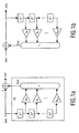
- Figure 1(a) shows a finite impulse response (FIR) type predictive filter 10 component of order K for a conventional LPC based encoder.
- the filter provides an estimate x ⁇ ( n ) for a given signal x(n) generated from a linear combination of K previous samples of the signal.
- the prediction coefficients ⁇ k are calculated based on some criterion, typically a weighted mean-squared error.
- the estimate x ⁇ ( n ) is in turn subtracted from the signal x(n) to provide a residual signal r ( n ).
- This residual signal and the information for the prediction filter i.e. the prediction coefficients ⁇ are generally transmitted or stored in a more efficient form.
- the prediction coefficients ⁇ k can be mapped onto a set of reflection coefficients, and these in turn can be mapped onto log area ratios (LAR).
- the prediction coefficients ⁇ k can be mapped directly to line spectral frequencies (LSF) prior to being encoded along with the residual signal in a bitstream representing the signal x(n) .
- LSF line spectral frequencies
- Alternative representations such as arcsine reflection coefficients (ASRCs) and Line Spectral Pairs (LSPs) may also be employed.
- an FIR type filter of the type described above does not enable an encoder to be tuned taking into account a psycho acoustic model of the auditory process.
- H k ( z ) 1 ⁇ ⁇ 2 1 ⁇ z ⁇ 1 ⁇ ⁇ z ⁇ 1 ⁇ ⁇ 1 ⁇ z ⁇ 1 ⁇ ⁇ k
- ⁇ ⁇ (-1, 1) the total transfer F may be a minimum-phase IIR filter.
- the preferred embodiments of the invention provide an extension of a conventional LPC scheme allowing Laguerre type prediction coefficients to be mapped to those of an FIR system. Therefore, conventional linear predictive coding techniques can be used to quantise and transmit or store the Laguerre prediction coefficients.
- the total transfer function F ( z ) can be represented as a combination of equations 2 and 3:
- the transfer function F(z) can be a minimum-phase system if the coefficients are optimised using, for example, a data-input windowing method as disclosed by Voitishchuk et al and den Brinker.
- the above filter is mapped onto a minimum-phase FIR filter of order K, so that these Laguerre type prediction coefficients can be quantised and transmitted by standard techniques.
- the encoder 14 includes a Laguerre filter component 16 of the type disclosed by by Voitishchuk et al and den Brinker.
- the component 16 is provided with a value of ⁇ which determines the frequency sensitivity of the filter. This value may either be encoded in a bitstream 50 produced by the encoder for later use by a decoder 22, Figure 3(b), or the value of ⁇ may otherwise be known by the decoder 22.
- the component For the signal x(n), the component provides a set of prediction coefficients ⁇ . These along with the ⁇ value are supplied to a synthesizer component 18, which produces an estimate of signal x ⁇ (n) in the manner shown in Figure 2(a).
- the prediction coefficients ⁇ are transformed in a transformation component 20.
- the coefficients c 0 ...c k are passed to a normalising component 26.
- the normalising component 26 passes the coefficients d 1 ...d k to a component 28 where the coefficients are transformed preferably into LAR or LSF parameters and quantized in a corresponding manner to the quantization of the ⁇ coefficients of Figure 1(a) except that indexing is different and the signs have been reversed.
- the component 28 also receives the residual signal r ( n ), quantizes this as appropriate and passes the values to a multiplexing unit 30 which generates a bitstream 50 representing the signal x(n). It will therefore be seen that this bitstream can be transmitted in the same form as with a bitstream containing conventional FIR filter parameters. Alternatively, the bitstream may be slightly modified to include at some point the value of ⁇ , but otherwise, its format need not be changed.
- bitstream 50 is decoded by a de-multiplexing unit 32.
- the extracted parameters are provided to a de-quantizing component which produces the residual signal r(n) and the normalized FIR type filter parameters d l ...d k in a conventional manner.
- an adapted encoder 14' provides peak broadening or bandwidth extension/expansion/widening as disclosed in "Spectral smoothing technique in PARCOR speech analysis-synthesis", Y. Tohkura and F. Itakura and S. Hashimoto, IEEE Trans. Acoust. Speech Signal Process. vol. 26, pp. 587-596, 1978.
- Spectral peak broadening in linear prediction coding is done by multiplying the impulse response (prediction coefficients) by an exponentially-decreasing sequence.
- peak broadening is implemented by interposing a peak broadening component 38 between the transform component 20 and an adapted normalizing component 26' of the first embodiment.
- the normalising component 26' can then normalise the coefficients c ⁇ 1 ...c ⁇ k to provide the normalised type FIR coefficients d 1...k as before.
- the peak broadening affects the signal which will eventually be synthesized within a decoder reading the peak broadened signal, and as such a different residual signal r(n) should be calculated within the encoder 14' if peak broadening has been applied.
- a de-quantizer component 34 as in Figure 2(b) is provided with the quantized signal produced by the component 28 to provide the coefficients d 1 ... k exactly as they would be generated within the decoder. These are in turn de-normalised and inversely transformed by components 36 and 24 respectively, again corresponding to the components of Figure 2(b), to produce a set of prediction coefficients ⁇ as would be generated within the decoder for the peak broadened signal.
- the synthesizer 18 then either uses the prediction coefficients ⁇ or ⁇ according to whether peak broadening has been applied or not and subtracts this from the signal x(n) to generate the residual signal r(n).
- the resulting prediction coefficients ⁇ are the coefficients of a spectrally peak broadened Laguerre prediction filter, where peak broadening has been carried out in a frequency warped domain.
- the encoder is in fact performing peak broadening on a psycho-acoustically relevant scale and also allow the peak broadening function, for example, w k , to be chosen on the basis of its pyscho-acoustical function.
- peak broadening could be applied to the coefficients d 1 ... k , rather than the coefficients c 0...k with the appropriate changes required for the generation of the residual signal.
- Figure 5 shows a more general form of encoder 14" encompassing the encoders of the first and second embodiments.
- the steps of transforming, normalising, quantizing and optionally peak broadening are performed as before by components 20, 26', 28 and 38/38' respectively.
- the components 38/38' indicate that peak broadening may occur either before 38 or after 38' normalizing
- the quantized signal is fed through de-quantizing, de-normalizing and inverse transform components 34, 36 and 24 respectively as in the second embodiment to ensure that the prediction coefficients employed by the encoder to generate the residual signal will be exactly the same as those employed in the decoder.
- the invention is not limited to the generation of a residual signal r(n) by synthesizing the signal x ⁇ (n) and subtracting this from the signal x(n) as in the first two embodiments.
- This aspect of the invention can be thought of more generally as including an encoder 18" which ideally uses the prediction coefficients which will be employed in the decoder and the frequency sensitizing parameter ⁇ to generate an indication b of the difference between the modelled aspect of the signal x(n) and the signal itself x(n) .
- a corresponding component combines this indication b with the prediction coefficients and the frequency sensitizing parameter ⁇ to generate the final estimate of the original audio signal.
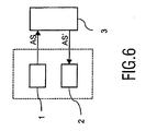
- Figure 6 shows an audio system according to the invention comprising an audio coder 1 including the encoder 14,14' as shown in Fig. 3(a) or 4 and an audio player 2 including the decoder 22 as shown in Figure 3(b).
- the encoded audio stream 50 is furnished from the audio coder to the audio player over a communication channel 3, which may be a 3 wireless connection, a data bus or a storage medium.
- the communication channel 3 is a storage medium, the storage medium may be fixed in the system or may also be a removable disc, solid state storage device such as a Memory StickTM from Sony Corporation etc.
- the communication channel 3 may be part of the audio system, but will however often be outside the audio system.
Abstract
Description
- The present invention relates to coding and decoding audio signals.
- Linear predictive coding (LPC) is often employed in audio and speech coding. Figure 1(a) shows a finite impulse response (FIR) type
predictive filter 10 component of order K for a conventional LPC based encoder. The filter provides an estimate x̂(n) for a given signal x(n) generated from a linear combination of K previous samples of the signal. In the example of Figure 1 (a), the transfer function of the filter F(z) relating x(n) and r(n) can be represented as follows:
- The prediction coefficients αk are calculated based on some criterion, typically a weighted mean-squared error.
- The estimate x̂(n) is in turn subtracted from the signal x(n) to provide a residual signal r(n). This residual signal and the information for the prediction filter i.e. the prediction coefficients α, are generally transmitted or stored in a more efficient form. For example, the prediction coefficients αk can be mapped onto a set of reflection coefficients, and these in turn can be mapped onto log area ratios (LAR). Alternatively, the prediction coefficients αk can be mapped directly to line spectral frequencies (LSF) prior to being encoded along with the residual signal in a bitstream representing the signal x(n). (In view of quantisation sensitivities, the LAR and LSF domains are preferred.) Alternative representations such as arcsine reflection coefficients (ASRCs) and Line Spectral Pairs (LSPs) may also be employed.
- In a decoder, Figure 1(b), the residual signal and the information for the prediction filter are used to reconstruct (or approximate) the original signal x(n). From Figure 1 it is clear that similar mechanisms appear in the encoder and decoder. It is important to note, however, that to ensure the stability of the decoder, particularly in relation to distortion that may have been introduced into the signal during quantization prior to encoding the bitstream for the signal x(n) that the filter F(z) is typically a minimum-phase filter. That is to say that all of the roots (poles and zeros) of the transfer function F(z) must be inside the unit circle and this is in general feasible to ensure for FIR filters.
- Using an FIR type filter of the type described above does not enable an encoder to be tuned taking into account a psycho acoustic model of the auditory process.
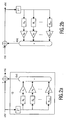
- In "Alternatives for Warped Linear Predictors", V. Voitishchuk et al., pp710-713, Proc. ProRISC Workshop CSSP, Veldhoven (NL), 29-30 Nov. 2001 and "Stability of Linear Predictive Structures using IIR filters", A.C. den Brinker, pp. 317-320, Proc. ProRISC Workshop CSSP, Veldhoven (NL), 29-30 Nov. 2001, it is shown that Laguerre and Kautz type filters which may be employed to tune an encoder/decoder towards ranges of frequencies of more interest and more normally thought of as Infinite Impulse Response (IIR) type filters may be represented in a form as shown in Figures 2(a) and 2(b).
- The total transfer function for the filter of Figure 2(a) relating x(n) and r(n) is:

where the set H k is a transfer function belonging to a set of stable, causal, linear and linearly-independent filters. - It has been shown that choosing the set H k as Laguerre filters, i.e.:

where λ ∈ (-1, 1), the total transfer F may be a minimum-phase IIR filter. - Where λ is real and greater than 0 modelling is shifted to lower frequencies to which the human ear is more sensitive, whereas when λ is less than 0, modelling is shifted towards higher frequencies. Where λ = 0 corresponds to the conventional case of Figure 1.
- There is, however, a problem in transmitting the prediction coefficients for filters of the type shown in Figure 2 in that the roots of the
polynomial 
- According to the present invention there are provided a method of encoding an audio signal as claimed in
claim 1, a method of decoding an audio stream as claimed in claim 9, an audio coder and an audio player as claimed inclaims 10 and 11, respectively, and an audio stream as claimed in claim 13. - The preferred embodiments of the invention provide an extension of a conventional LPC scheme allowing Laguerre type prediction coefficients to be mapped to those of an FIR system. Therefore, conventional linear predictive coding techniques can be used to quantise and transmit or store the Laguerre prediction coefficients.
- Embodiments of the present invention will now be described with reference to the accompanying drawings, in which:
- Figures 1(a) and 1(b) show an encoder and decoder respectively for a conventional linear prediction structure;
- Figures 2(a) and 2(b) show an encoder and decoder respectively for an alternative linear prediction scheme;
- Figure 3(a) and 3(b) show an encoder and decoder respectively for a linear prediction scheme according to a first embodiment of the present invention;
- Figure 4 shows an encoder according to a second embodiment of the invention;
- Figure 5 shows a generic encoder encompassing the first and second embodiments of the invention; and
- Figure 6 shows a system comprising an audio coder and an audio player.
- For a Laguerre type filter represented using the schema of Figure 2, the total transfer function F(z) can be represented as a combination of
equations 2 and 3:
- It is known that the transfer function F(z) can be a minimum-phase system if the coefficients are optimised using, for example, a data-input windowing method as disclosed by Voitishchuk et al and den Brinker.
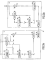
- In a first embodiment of the present invention, the above filter is mapped onto a minimum-phase FIR filter of order K, so that these Laguerre type prediction coefficients can be quantised and transmitted by standard techniques.
- Referring now to Figure 3(a) which shows an
encoder 14 according to the first embodiment of the present invention. Theencoder 14 includes a Laguerrefilter component 16 of the type disclosed by by Voitishchuk et al and den Brinker. Thecomponent 16 is provided with a value of λ which determines the frequency sensitivity of the filter. This value may either be encoded in abitstream 50 produced by the encoder for later use by adecoder 22, Figure 3(b), or the value of λ may otherwise be known by thedecoder 22. - For the signal x(n), the component provides a set of prediction coefficients α. These along with the λ value are supplied to a
synthesizer component 18, which produces an estimate of signal x̂(n) in the manner shown in Figure 2(a). - In the preferred embodiments, however, the prediction coefficients α are transformed in a
transformation component 20. The transformation carried out by thecomponent 20 is illustrated using the form of an upper Triangular Toeplitz matrix as follows:
where α are the Laguerre prediction coefficients and

- In the
decoder 22, Figure 3(b), an inverse transformation is performed by acomponent 24 on the coefficients c0...ck generated by the forward transformation component. Thecomponent 24 is supplied with the same λ as employed by theencoder 14, and the transformation carried out by thecomponent 24 is illustrated using the form of an upper Triangular Toeplitz as follows:
- From this inverse transformation, it will be seen that:
The coefficients (c0...ck) adhere to a linear constraint, namely
The parameter c0 can be considered as redundant since α0...αk-1 can be reconstructed from c1...ck, as follows:
- Reverting back to the
encoder 14, in the first embodiment, the coefficients c0...ck are passed to a normalisingcomponent 26. The component divides the coefficients c0...ck by the value of c0 to provide a set of coefficients d0...dk. It will be seen, however, that the value of d0 is always 1 and so the coefficients d1...dk correspond to the prediction coefficients of a minimum phase FIR filter of order K with transfer function
component 26 is merely a division of all coefficients by some factor, the order of thetransformation component 20 and thenormalisation component 26 can be changed, i.e. we can do first normalisation and then transformation. In the encoder this requires the calculation of c0 first with corresponding changes afterwards. It will also be seen that the same change in order of inverse transformation and de-normalisation can be made in the decoder explained later. - The normalising
component 26 passes the coefficients d1...dk to acomponent 28 where the coefficients are transformed preferably into LAR or LSF parameters and quantized in a corresponding manner to the quantization of the α coefficients of Figure 1(a) except that indexing is different and the signs have been reversed. Thecomponent 28 also receives the residual signal r(n), quantizes this as appropriate and passes the values to amultiplexing unit 30 which generates abitstream 50 representing the signal x(n). It will therefore be seen that this bitstream can be transmitted in the same form as with a bitstream containing conventional FIR filter parameters. Alternatively, the bitstream may be slightly modified to include at some point the value of λ, but otherwise, its format need not be changed. - Turning now to the
decoder 22, Figure 3(b), thebitstream 50 is decoded by ade-multiplexing unit 32. The extracted parameters are provided to a de-quantizing component which produces the residual signal r(n) and the normalized FIR type filter parameters dl...dk in a conventional manner. - A
de-normalizing component 36 is employed first of all to determine the value of c0. From equation 5, it can be seen that:
and so thecomponent 36 when provided with the value λ used in the encoder can use the equation:
to determine the value for c0. For equation 7, it should be noted that while the de-normalizing component is only provided with parameters d1...dk, it can assume that d0=1. Thus, once c0 has been determined the remaining coefficients c1..,ck are determined by thecomponent 36 as follows:
The coefficients c0...ck are provided by thede-normalizing component 36 to theinverse transformation unit 24 described above, and this provides the set of Laguerre filter prediction coefficents α which can in turn be used by a decoder synthesizer component 18' as shown in Figure 2(b) to produce the estimated signal x̂(n). This is combined with the residual signal r(n) supplied by thede-quantizer component 34 to provide the finally decoded signal x(n). - It will be seen that variations of the preferred embodiment are possible. For example, in a second embodiment of the invention, Figure 4, an adapted encoder 14' provides peak broadening or bandwidth extension/expansion/widening as disclosed in "Spectral smoothing technique in PARCOR speech analysis-synthesis", Y. Tohkura and F. Itakura and S. Hashimoto, IEEE Trans. Acoust. Speech Signal Process. vol. 26, pp. 587-596, 1978. Spectral peak broadening in linear prediction coding is done by multiplying the impulse response (prediction coefficients) by an exponentially-decreasing sequence.
- In relation to the present invention, peak broadening is implemented by interposing a
peak broadening component 38 between thetransform component 20 and an adapted normalizing component 26' of the first embodiment. - After the transformation of the original Laguerre filter type prediction coefficients α to the coefficients c0...ck, the encoder determines if peak broadening is required. If so, the coefficients c0...ck are passed to the
peak broadening component 38. This multiplies the coefficients c0...ck with a peak broadening response, for example, of the form:
As before, a linear constraint needs to be applied to the coefficients c̃. Thus, if supplied with a peak broadened set of coefficients, either thecomponent 38 or 26' determines a multiplier cf as follows:
The coefficients c̃ k are divided by this multiplier c̃ k = c̃ k /c f so that the resulting coefficients c̅ fulfil the constraints of equation 5. The normalising component 26' can then normalise the coefficients c̅1...c̅ k to provide the normalised type FIR coefficients d1...k as before. - It will be seen that the peak broadening affects the signal which will eventually be synthesized within a decoder reading the peak broadened signal, and as such a different residual signal r(n) should be calculated within the encoder 14' if peak broadening has been applied.
- Thus, in the second embodiment, a
de-quantizer component 34 as in Figure 2(b) is provided with the quantized signal produced by thecomponent 28 to provide the coefficients d1...k exactly as they would be generated within the decoder. These are in turn de-normalised and inversely transformed bycomponents synthesizer 18 then either uses the prediction coefficients α̅ or α according to whether peak broadening has been applied or not and subtracts this from the signal x(n) to generate the residual signal r(n). - It will be seen that, if the coefficients c̃ 0...c̃ k or c̅ 0 ...c̅ k were provided directly to the
inverse transform component 24, the same prediction coefficients α̅ would not be provided as above. Nonetheless, this would obviate the need for thecomponents - When a bitstream to which such peak broadening is decoded, the resulting prediction coefficients α̅ are the coefficients of a spectrally peak broadened Laguerre prediction filter, where peak broadening has been carried out in a frequency warped domain. This means that the encoder is in fact performing peak broadening on a psycho-acoustically relevant scale and also allow the peak broadening function, for example, w k , to be chosen on the basis of its pyscho-acoustical function.
- It will be seen that in variations of the second embodiment, peak broadening could be applied to the coefficients d1 ... k, rather than the coefficients c0...k with the appropriate changes required for the generation of the residual signal.
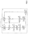
- As explained above, it is desireable to ensure that the prediction coefficients used within the encoder will be the same as those employed within the decoder to generate the final estimate of the original audio signal. Figure 5 shows a more general form of
encoder 14" encompassing the encoders of the first and second embodiments. In this encoder, the steps of transforming, normalising, quantizing and optionally peak broadening are performed as before bycomponents components 38/38' indicate that peak broadening may occur either before 38 or after 38' normalizing) - In the general form of encoder, however, the quantized signal is fed through de-quantizing, de-normalizing and
inverse transform components - It will also be seen from Figure 5 that the invention is not limited to the generation of a residual signal r(n) by synthesizing the signal x̂(n) and subtracting this from the signal x(n) as in the first two embodiments. This aspect of the invention can be thought of more generally as including an
encoder 18" which ideally uses the prediction coefficients which will be employed in the decoder and the frequency sensitizing parameter λ to generate an indication b of the difference between the modelled aspect of the signal x(n) and the signal itself x(n). - In the decoder (not shown), a corresponding component combines this indication b with the prediction coefficients and the frequency sensitizing parameter λ to generate the final estimate of the original audio signal.
- Figure 6 shows an audio system according to the invention comprising an
audio coder 1 including theencoder 14,14' as shown in Fig. 3(a) or 4 and anaudio player 2 including thedecoder 22 as shown in Figure 3(b). The encodedaudio stream 50 is furnished from the audio coder to the audio player over acommunication channel 3, which may be a 3 wireless connection, a data bus or a storage medium. In case thecommunication channel 3 is a storage medium, the storage medium may be fixed in the system or may also be a removable disc, solid state storage device such as a Memory Stick™ from Sony Corporation etc. Thecommunication channel 3 may be part of the audio system, but will however often be outside the audio system. - It should be noted that the above-mentioned embodiments illustrate rather than limit the invention, and that those skilled in the art will be able to design many alternative embodiments without departing from the scope of the appended claims. In the claims, any reference signs placed between parentheses shall not be construed as limiting the claim. The word 'comprising' does not exclude the presence of other elements or steps than those listed in a claim. The invention can be implemented by means of hardware comprising several distinct elements, and by means of a suitably programmed computer. In a device claim enumerating several means, several of these means can be embodied by one and the same item of hardware. The mere fact that certain measures are recited in mutually different dependent claims does not indicate that a combination of these measures cannot be used to advantage.
Claims (14)
- A method of encoding an audio signal, the method comprising the steps of:modelling the audio signal in accordance with a frequency sensitizing parameter to provide a first set of infinite impulse response filter type characteristics of an order K capable of being linearly combined with said sensitizing parameter to provide an estimate for said audio signal;transforming said first or a third set of characteristics as a function of said sensitizing parameter to provide a second set of characteristics compatible with finite impulse response filter type characteristics;normalising said second or said first set of characteristics, respectively, to provide said third set of characteristics; andgenerating an encoded audio stream including representations of a transformed and normalised set of characteristics of order K.
- A method as claimed in claim 1 wherein said IIR filter type filter characteristics satisfy the requirements of a minimum phase filter and said FIR filter type characteristics satisfy the requirements of a minimum phase filter.
- A method according to claim 1 further comprising the step of:subtracting said estimate from said audio signal to provide a residual signal; and wherein said generating step includes including said residual signal in said encoded audio stream.
- A method according to claim 1 wherein said modelling step comprises modelling said audio signal with a Laguerre type filter having a transfer function:

- A method according to claim 4 wherein said transformation step comprises transforming said Laguerre filter coefficients according to the matrix transformation:

wherein
- A method according to claim 5 wherein said normalising step comprises dividing said second set of characteristics of order K+1 by one of said second set of characteristics and providing the remainder of said divided set of characteristics as said third set of characteristics of order K.
- A method according to claim 1 wherein said generating step includes said frequency sensitizing parameter in said bitstream.
- A method according to claim 1 further comprising the step of: peak broadening said set of characteristics of order K+1.
- Method of decoding an audio stream, the method comprising the steps of:reading an encoded audio stream containing representations of an audio signal to provide a first set of characteristics of an order K compatible with finite impulse response filter type characteristics;combining said first set of characteristics of order K with a frequency sensitizing parameter to provide a de-normalising characteristic;de-normalising said first or a third infinite impulse response filter type set of characteristics as a function of said de-normalising characteristic to provide a second set of characteristics; transforming said second or said first set of characteristics, respectively, as a function of said sensitizing parameter to provide said third set of characteristics; andsynthesizing the audio signal as a linear combination of said frequency sensitizing parameter and a set of de-normalised and transformed characteristics of order K.
- Audio coder, comprising:means for modelling an audio signal in accordance with a frequency sensitizing parameter to provide a first set of infinite impulse response filter type characteristics of an order K capable of being linearly combined with said sensitizing parameter to provide an estimate for said audio signal;means for transforming said first or a third set of characteristics as a function of said sensitizing parameter to provide a second set of characteristics compatible with finite impulse response filter type characteristics;means for normalising said second or said first set of characteristics, respectively, to provide said third set of characteristics; andmeans for generating an encoded audio stream including representations of a transformed and normalised set of characteristics of order K.
- Audio player, comprising:means for reading an encoded audio stream containing representations of an audio signal to provide a first set of characteristics of an order K compatible with finite impulse response filter type characteristics;means for combining said first set of characteristics of order K with a frequency sensitizing parameter to provide a de-normalising characteristic;means for de-normalising said first or a third infinite impulse response filter type set of characteristics as a function of said de-normalising characteristic to provide a second set of characteristics;means for transforming said second or said first set of characteristics, respectively, as a function of said sensitizing parameter to provide said third set of characteristics; andmeans for synthesizing the audio signal as a linear combination of said frequency sensitizing parameter and a set of de-normalised and transformed characteristics of order K.
- Audio system comprising an audio coder as claimed in claim 10 and an audio player as claimed in claim 11.
- Audio stream comprising representations of an audio signal corresponding to a set of characteristics of an order K, said set of characteristics of order K being combinable with a frequency sensitizing parameter to provide a set of characteristics of order K+1 compatible with finite impulse response filter type characteristics; said set of characteristics of order K+1 being transformable as a function of said sensitizing parameter to provide a set of infinite impulse response filter type characteristics of order K.
- Storage medium on which an audio stream as claimed in claim 13 has been stored.
Priority Applications (1)
| Application Number | Priority Date | Filing Date | Title |
|---|---|---|---|
| EP03722975A EP1514262B1 (en) | 2002-05-30 | 2003-05-16 | Audio coding |
Applications Claiming Priority (4)
| Application Number | Priority Date | Filing Date | Title |
|---|---|---|---|
| EP02077128 | 2002-05-30 | ||
| EP02077128 | 2002-05-30 | ||
| EP03722975A EP1514262B1 (en) | 2002-05-30 | 2003-05-16 | Audio coding |
| PCT/IB2003/002044 WO2003102922A1 (en) | 2002-05-30 | 2003-05-16 | Audio coding |
Publications (2)
| Publication Number | Publication Date |
|---|---|
| EP1514262A1 EP1514262A1 (en) | 2005-03-16 |
| EP1514262B1 true EP1514262B1 (en) | 2006-08-16 |
Family
ID=29595018
Family Applications (1)
| Application Number | Title | Priority Date | Filing Date |
|---|---|---|---|
| EP03722975A Expired - Lifetime EP1514262B1 (en) | 2002-05-30 | 2003-05-16 | Audio coding |
Country Status (9)
| Country | Link |
|---|---|
| US (1) | US20050228656A1 (en) |
| EP (1) | EP1514262B1 (en) |
| JP (1) | JP4446883B2 (en) |
| KR (1) | KR101038446B1 (en) |
| CN (1) | CN100343895C (en) |
| AT (1) | ATE336781T1 (en) |
| AU (1) | AU2003230132A1 (en) |
| DE (1) | DE60307634T2 (en) |
| WO (1) | WO2003102922A1 (en) |
Families Citing this family (7)
| Publication number | Priority date | Publication date | Assignee | Title |
|---|---|---|---|---|
| KR20080015878A (en) * | 2005-05-25 | 2008-02-20 | 코닌클리케 필립스 일렉트로닉스 엔.브이. | Predictive encoding of a multi channel signal |
| DE102006022346B4 (en) * | 2006-05-12 | 2008-02-28 | Fraunhofer-Gesellschaft zur Förderung der angewandten Forschung e.V. | Information signal coding |
| TWI538000B (en) * | 2012-05-10 | 2016-06-11 | 杜比實驗室特許公司 | Multistage filter, audio encoder, audio decoder, method of performing multistage filtering, method for encoding audio data, method for decoding encoded audio data, and method and apparatus for processing encoded bitstream |
| CN104737463B (en) * | 2012-06-18 | 2018-03-16 | 瑞典爱立信有限公司 | pre-filtering in MIMO receiver |
| US9548056B2 (en) * | 2012-12-19 | 2017-01-17 | Dolby International Ab | Signal adaptive FIR/IIR predictors for minimizing entropy |
| PL3462448T3 (en) * | 2014-01-24 | 2020-08-10 | Nippon Telegraph And Telephone Corporation | Linear predictive analysis apparatus, method, program and recording medium |
| CN109188069B (en) * | 2018-08-29 | 2020-08-28 | 广东石油化工学院 | Pulse noise filtering method for load switch event detection |
Family Cites Families (4)
| Publication number | Priority date | Publication date | Assignee | Title |
|---|---|---|---|---|
| US4493048A (en) * | 1982-02-26 | 1985-01-08 | Carnegie-Mellon University | Systolic array apparatuses for matrix computations |
| US7423983B1 (en) * | 1999-09-20 | 2008-09-09 | Broadcom Corporation | Voice and data exchange over a packet based network |
| JP2001134295A (en) * | 1999-08-23 | 2001-05-18 | Sony Corp | Encoder and encoding method, recorder and recording method, transmitter and transmission method, decoder and decoding method, reproducing device and reproducing method, and recording medium |
| US6931373B1 (en) * | 2001-02-13 | 2005-08-16 | Hughes Electronics Corporation | Prototype waveform phase modeling for a frequency domain interpolative speech codec system |
-
2003
- 2003-05-16 CN CNB038122014A patent/CN100343895C/en not_active Expired - Fee Related
- 2003-05-16 AT AT03722975T patent/ATE336781T1/en not_active IP Right Cessation
- 2003-05-16 JP JP2004509924A patent/JP4446883B2/en not_active Expired - Fee Related
- 2003-05-16 EP EP03722975A patent/EP1514262B1/en not_active Expired - Lifetime
- 2003-05-16 KR KR1020047019512A patent/KR101038446B1/en active IP Right Grant
- 2003-05-16 WO PCT/IB2003/002044 patent/WO2003102922A1/en active IP Right Grant
- 2003-05-16 US US10/515,746 patent/US20050228656A1/en not_active Abandoned
- 2003-05-16 AU AU2003230132A patent/AU2003230132A1/en not_active Abandoned
- 2003-05-16 DE DE60307634T patent/DE60307634T2/en not_active Expired - Lifetime
Also Published As
| Publication number | Publication date |
|---|---|
| KR101038446B1 (en) | 2011-06-01 |
| US20050228656A1 (en) | 2005-10-13 |
| KR20050007574A (en) | 2005-01-19 |
| DE60307634T2 (en) | 2007-08-09 |
| EP1514262A1 (en) | 2005-03-16 |
| DE60307634D1 (en) | 2006-09-28 |
| CN1656537A (en) | 2005-08-17 |
| JP2005528646A (en) | 2005-09-22 |
| WO2003102922A1 (en) | 2003-12-11 |
| AU2003230132A1 (en) | 2003-12-19 |
| CN100343895C (en) | 2007-10-17 |
| ATE336781T1 (en) | 2006-09-15 |
| JP4446883B2 (en) | 2010-04-07 |
Similar Documents
| Publication | Publication Date | Title |
|---|---|---|
| EP1527441B1 (en) | Audio coding | |
| US6732070B1 (en) | Wideband speech codec using a higher sampling rate in analysis and synthesis filtering than in excitation searching | |
| Gersho | Advances in speech and audio compression | |
| CA2140329C (en) | Decomposition in noise and periodic signal waveforms in waveform interpolation | |
| RU2389085C2 (en) | Method and device for introducing low-frequency emphasis when compressing sound based on acelp/tcx | |
| EP3244407B1 (en) | Apparatus and method for modifying a parameterized representation | |
| RU2388068C2 (en) | Temporal and spatial generation of multichannel audio signals | |
| US20070147518A1 (en) | Methods and devices for low-frequency emphasis during audio compression based on ACELP/TCX | |
| EP0747882A2 (en) | Pitch delay modification during frame erasures | |
| US20090192792A1 (en) | Methods and apparatuses for encoding and decoding audio signal | |
| US20070198274A1 (en) | Scalable audio coding | |
| EP1756807B1 (en) | Audio encoding | |
| US6778953B1 (en) | Method and apparatus for representing masked thresholds in a perceptual audio coder | |
| EP1385150B1 (en) | Method and system for parametric characterization of transient audio signals | |
| EP1514262B1 (en) | Audio coding | |
| EP0926659B1 (en) | Speech encoding and decoding method | |
| JPH10124089A (en) | Processor and method for speech signal processing and device and method for expanding voice bandwidth | |
| JP4281131B2 (en) | Signal encoding apparatus and method, and signal decoding apparatus and method | |
| JP2000132194A (en) | Signal encoding device and method therefor, and signal decoding device and method therefor | |
| EP1563490B1 (en) | Method and apparatus for generating audio components | |
| JP3437421B2 (en) | Tone encoding apparatus, tone encoding method, and recording medium recording tone encoding program | |
| den Brinker et al. | Pure linear prediction | |
| JP4618823B2 (en) | Signal encoding apparatus and method | |
| Yuan | The weighted sum of the line spectrum pair for noisy speech | |
| Gersho | Advances in speech and audio compression |
Legal Events
| Date | Code | Title | Description |
|---|---|---|---|
| PUAI | Public reference made under article 153(3) epc to a published international application that has entered the european phase |
Free format text: ORIGINAL CODE: 0009012 |
|
| 17P | Request for examination filed |
Effective date: 20041230 |
|
| AK | Designated contracting states |
Kind code of ref document: A1 Designated state(s): AT BE BG CH CY CZ DE DK EE ES FI FR GB GR HU IE IT LI LU MC NL PT RO SE SI SK TR |
|
| AX | Request for extension of the european patent |
Extension state: AL LT LV MK |
|
| GRAP | Despatch of communication of intention to grant a patent |
Free format text: ORIGINAL CODE: EPIDOSNIGR1 |
|
| DAX | Request for extension of the european patent (deleted) | ||
| GRAS | Grant fee paid |
Free format text: ORIGINAL CODE: EPIDOSNIGR3 |
|
| GRAA | (expected) grant |
Free format text: ORIGINAL CODE: 0009210 |
|
| AK | Designated contracting states |
Kind code of ref document: B1 Designated state(s): AT BE BG CH CY CZ DE DK EE ES FI FR GB GR HU IE IT LI LU MC NL PT RO SE SI SK TR |
|
| PG25 | Lapsed in a contracting state [announced via postgrant information from national office to epo] |
Ref country code: IT Free format text: LAPSE BECAUSE OF FAILURE TO SUBMIT A TRANSLATION OF THE DESCRIPTION OR TO PAY THE FEE WITHIN THE PRESCRIBED TIME-LIMIT;WARNING: LAPSES OF ITALIAN PATENTS WITH EFFECTIVE DATE BEFORE 2007 MAY HAVE OCCURRED AT ANY TIME BEFORE 2007. THE CORRECT EFFECTIVE DATE MAY BE DIFFERENT FROM THE ONE RECORDED. Effective date: 20060816 Ref country code: BE Free format text: LAPSE BECAUSE OF FAILURE TO SUBMIT A TRANSLATION OF THE DESCRIPTION OR TO PAY THE FEE WITHIN THE PRESCRIBED TIME-LIMIT Effective date: 20060816 Ref country code: NL Free format text: LAPSE BECAUSE OF FAILURE TO SUBMIT A TRANSLATION OF THE DESCRIPTION OR TO PAY THE FEE WITHIN THE PRESCRIBED TIME-LIMIT Effective date: 20060816 Ref country code: LI Free format text: LAPSE BECAUSE OF FAILURE TO SUBMIT A TRANSLATION OF THE DESCRIPTION OR TO PAY THE FEE WITHIN THE PRESCRIBED TIME-LIMIT Effective date: 20060816 Ref country code: CZ Free format text: LAPSE BECAUSE OF FAILURE TO SUBMIT A TRANSLATION OF THE DESCRIPTION OR TO PAY THE FEE WITHIN THE PRESCRIBED TIME-LIMIT Effective date: 20060816 Ref country code: FI Free format text: LAPSE BECAUSE OF FAILURE TO SUBMIT A TRANSLATION OF THE DESCRIPTION OR TO PAY THE FEE WITHIN THE PRESCRIBED TIME-LIMIT Effective date: 20060816 Ref country code: SK Free format text: LAPSE BECAUSE OF FAILURE TO SUBMIT A TRANSLATION OF THE DESCRIPTION OR TO PAY THE FEE WITHIN THE PRESCRIBED TIME-LIMIT Effective date: 20060816 Ref country code: RO Free format text: LAPSE BECAUSE OF FAILURE TO SUBMIT A TRANSLATION OF THE DESCRIPTION OR TO PAY THE FEE WITHIN THE PRESCRIBED TIME-LIMIT Effective date: 20060816 Ref country code: AT Free format text: LAPSE BECAUSE OF FAILURE TO SUBMIT A TRANSLATION OF THE DESCRIPTION OR TO PAY THE FEE WITHIN THE PRESCRIBED TIME-LIMIT Effective date: 20060816 Ref country code: CH Free format text: LAPSE BECAUSE OF FAILURE TO SUBMIT A TRANSLATION OF THE DESCRIPTION OR TO PAY THE FEE WITHIN THE PRESCRIBED TIME-LIMIT Effective date: 20060816 Ref country code: SI Free format text: LAPSE BECAUSE OF FAILURE TO SUBMIT A TRANSLATION OF THE DESCRIPTION OR TO PAY THE FEE WITHIN THE PRESCRIBED TIME-LIMIT Effective date: 20060816 |
|
| REG | Reference to a national code |
Ref country code: GB Ref legal event code: FG4D |
|
| REG | Reference to a national code |
Ref country code: CH Ref legal event code: EP |
|
| REG | Reference to a national code |
Ref country code: IE Ref legal event code: FG4D |
|
| REF | Corresponds to: |
Ref document number: 60307634 Country of ref document: DE Date of ref document: 20060928 Kind code of ref document: P |
|
| PG25 | Lapsed in a contracting state [announced via postgrant information from national office to epo] |
Ref country code: SE Free format text: LAPSE BECAUSE OF FAILURE TO SUBMIT A TRANSLATION OF THE DESCRIPTION OR TO PAY THE FEE WITHIN THE PRESCRIBED TIME-LIMIT Effective date: 20061116 Ref country code: BG Free format text: LAPSE BECAUSE OF FAILURE TO SUBMIT A TRANSLATION OF THE DESCRIPTION OR TO PAY THE FEE WITHIN THE PRESCRIBED TIME-LIMIT Effective date: 20061116 Ref country code: DK Free format text: LAPSE BECAUSE OF FAILURE TO SUBMIT A TRANSLATION OF THE DESCRIPTION OR TO PAY THE FEE WITHIN THE PRESCRIBED TIME-LIMIT Effective date: 20061116 |
|
| PG25 | Lapsed in a contracting state [announced via postgrant information from national office to epo] |
Ref country code: ES Free format text: LAPSE BECAUSE OF FAILURE TO SUBMIT A TRANSLATION OF THE DESCRIPTION OR TO PAY THE FEE WITHIN THE PRESCRIBED TIME-LIMIT Effective date: 20061127 |
|
| PG25 | Lapsed in a contracting state [announced via postgrant information from national office to epo] |
Ref country code: PT Free format text: LAPSE BECAUSE OF FAILURE TO SUBMIT A TRANSLATION OF THE DESCRIPTION OR TO PAY THE FEE WITHIN THE PRESCRIBED TIME-LIMIT Effective date: 20070116 |
|
| NLV1 | Nl: lapsed or annulled due to failure to fulfill the requirements of art. 29p and 29m of the patents act | ||
| REG | Reference to a national code |
Ref country code: CH Ref legal event code: PL |
|
| ET | Fr: translation filed | ||
| PLBE | No opposition filed within time limit |
Free format text: ORIGINAL CODE: 0009261 |
|
| STAA | Information on the status of an ep patent application or granted ep patent |
Free format text: STATUS: NO OPPOSITION FILED WITHIN TIME LIMIT |
|
| 26N | No opposition filed |
Effective date: 20070518 |
|
| PG25 | Lapsed in a contracting state [announced via postgrant information from national office to epo] |
Ref country code: MC Free format text: LAPSE BECAUSE OF NON-PAYMENT OF DUE FEES Effective date: 20070531 |
|
| PG25 | Lapsed in a contracting state [announced via postgrant information from national office to epo] |
Ref country code: GR Free format text: LAPSE BECAUSE OF FAILURE TO SUBMIT A TRANSLATION OF THE DESCRIPTION OR TO PAY THE FEE WITHIN THE PRESCRIBED TIME-LIMIT Effective date: 20061117 |
|
| PG25 | Lapsed in a contracting state [announced via postgrant information from national office to epo] |
Ref country code: IE Free format text: LAPSE BECAUSE OF NON-PAYMENT OF DUE FEES Effective date: 20070516 |
|
| PG25 | Lapsed in a contracting state [announced via postgrant information from national office to epo] |
Ref country code: EE Free format text: LAPSE BECAUSE OF FAILURE TO SUBMIT A TRANSLATION OF THE DESCRIPTION OR TO PAY THE FEE WITHIN THE PRESCRIBED TIME-LIMIT Effective date: 20060816 |
|
| PG25 | Lapsed in a contracting state [announced via postgrant information from national office to epo] |
Ref country code: LU Free format text: LAPSE BECAUSE OF NON-PAYMENT OF DUE FEES Effective date: 20070516 Ref country code: CY Free format text: LAPSE BECAUSE OF FAILURE TO SUBMIT A TRANSLATION OF THE DESCRIPTION OR TO PAY THE FEE WITHIN THE PRESCRIBED TIME-LIMIT Effective date: 20060816 |
|
| PG25 | Lapsed in a contracting state [announced via postgrant information from national office to epo] |
Ref country code: TR Free format text: LAPSE BECAUSE OF FAILURE TO SUBMIT A TRANSLATION OF THE DESCRIPTION OR TO PAY THE FEE WITHIN THE PRESCRIBED TIME-LIMIT Effective date: 20060816 Ref country code: HU Free format text: LAPSE BECAUSE OF FAILURE TO SUBMIT A TRANSLATION OF THE DESCRIPTION OR TO PAY THE FEE WITHIN THE PRESCRIBED TIME-LIMIT Effective date: 20070217 |
|
| REG | Reference to a national code |
Ref country code: DE Ref legal event code: R082 Ref document number: 60307634 Country of ref document: DE Representative=s name: VOLMER, GEORG, DIPL.-ING., DE |
|
| REG | Reference to a national code |
Ref country code: DE Ref legal event code: R082 Ref document number: 60307634 Country of ref document: DE Representative=s name: MEISSNER, BOLTE & PARTNER GBR, DE Effective date: 20140328 Ref country code: DE Ref legal event code: R082 Ref document number: 60307634 Country of ref document: DE Representative=s name: MEISSNER BOLTE PATENTANWAELTE RECHTSANWAELTE P, DE Effective date: 20140328 Ref country code: DE Ref legal event code: R082 Ref document number: 60307634 Country of ref document: DE Representative=s name: VOLMER, GEORG, DIPL.-ING., DE Effective date: 20140328 Ref country code: DE Ref legal event code: R081 Ref document number: 60307634 Country of ref document: DE Owner name: KONINKLIJKE PHILIPS N.V., NL Free format text: FORMER OWNER: KONINKLIJKE PHILIPS ELECTRONICS N.V., EINDHOVEN, NL Effective date: 20140328 |
|
| REG | Reference to a national code |
Ref country code: FR Ref legal event code: CD Owner name: KONINKLIJKE PHILIPS N.V., NL Effective date: 20141126 Ref country code: FR Ref legal event code: CA Effective date: 20141126 |
|
| REG | Reference to a national code |
Ref country code: DE Ref legal event code: R082 Ref document number: 60307634 Country of ref document: DE Representative=s name: MEISSNER, BOLTE & PARTNER GBR, DE Ref country code: DE Ref legal event code: R082 Ref document number: 60307634 Country of ref document: DE Representative=s name: MEISSNER BOLTE PATENTANWAELTE RECHTSANWAELTE P, DE |
|
| REG | Reference to a national code |
Ref country code: FR Ref legal event code: PLFP Year of fee payment: 14 |
|
| REG | Reference to a national code |
Ref country code: FR Ref legal event code: PLFP Year of fee payment: 15 |
|
| REG | Reference to a national code |
Ref country code: FR Ref legal event code: PLFP Year of fee payment: 16 |
|
| PGFP | Annual fee paid to national office [announced via postgrant information from national office to epo] |
Ref country code: FR Payment date: 20190527 Year of fee payment: 17 |
|
| PGFP | Annual fee paid to national office [announced via postgrant information from national office to epo] |
Ref country code: DE Payment date: 20190731 Year of fee payment: 17 Ref country code: GB Payment date: 20190529 Year of fee payment: 17 |
|
| REG | Reference to a national code |
Ref country code: DE Ref legal event code: R119 Ref document number: 60307634 Country of ref document: DE |
|
| GBPC | Gb: european patent ceased through non-payment of renewal fee |
Effective date: 20200516 |
|
| PG25 | Lapsed in a contracting state [announced via postgrant information from national office to epo] |
Ref country code: FR Free format text: LAPSE BECAUSE OF NON-PAYMENT OF DUE FEES Effective date: 20200531 Ref country code: GB Free format text: LAPSE BECAUSE OF NON-PAYMENT OF DUE FEES Effective date: 20200516 |
|
| PG25 | Lapsed in a contracting state [announced via postgrant information from national office to epo] |
Ref country code: DE Free format text: LAPSE BECAUSE OF NON-PAYMENT OF DUE FEES Effective date: 20201201 |