EP1514207B1 - Wireless pick-and-pack system - Google Patents
Wireless pick-and-pack system Download PDFInfo
- Publication number
- EP1514207B1 EP1514207B1 EP03734330A EP03734330A EP1514207B1 EP 1514207 B1 EP1514207 B1 EP 1514207B1 EP 03734330 A EP03734330 A EP 03734330A EP 03734330 A EP03734330 A EP 03734330A EP 1514207 B1 EP1514207 B1 EP 1514207B1
- Authority
- EP
- European Patent Office
- Prior art keywords
- item
- entry
- signal
- transmitter
- indicator
- Prior art date
- Legal status (The legal status is an assumption and is not a legal conclusion. Google has not performed a legal analysis and makes no representation as to the accuracy of the status listed.)
- Expired - Lifetime
Links
Images


Classifications
-
- G—PHYSICS
- G06—COMPUTING OR CALCULATING; COUNTING
- G06Q—INFORMATION AND COMMUNICATION TECHNOLOGY [ICT] SPECIALLY ADAPTED FOR ADMINISTRATIVE, COMMERCIAL, FINANCIAL, MANAGERIAL OR SUPERVISORY PURPOSES; SYSTEMS OR METHODS SPECIALLY ADAPTED FOR ADMINISTRATIVE, COMMERCIAL, FINANCIAL, MANAGERIAL OR SUPERVISORY PURPOSES, NOT OTHERWISE PROVIDED FOR
- G06Q10/00—Administration; Management
- G06Q10/08—Logistics, e.g. warehousing, loading or distribution; Inventory or stock management
- G06Q10/087—Inventory or stock management, e.g. order filling, procurement or balancing against orders
Definitions
- Various implementations in this description relate generally to communications for identifying product locations and, more particularly, to infrared pick and pack systems.
- Manual picking and packing of goods in a warehouse or storage area environment typically involves a human picker traversing a warehouse or similar storage area and selecting, by hand, the goods corresponding to entries in a list.
- This list is commonly known as a picklist, and as each good in the picklist is selected, the picker typically packs it away for shipment or processing.
- pick-to-light systems have been developed. Typical pick-to-light systems provide pickers with a visual cue as to the location of the storage container or storage subarea that contains the goods corresponding to the entries in the picklist.
- some pick-to-light systems include lights attached to or positioned near each storage subarea (for example, a shelf or designated floor space) or storage container (for example, a bin or a crate) in the storage area.
- the lights provide a visual cue to the picker by illuminating or flashing if the corresponding storage subarea or storage container contains the goods in the picklist.
- Other pick-to-light systems include a light emitting diode (LED) display associated with a set of storage containers or storage subareas.
- the LED display is typically an alphanumeric display that provides a picker with the coordinates of the containers or subareas that contain the goods in the picklist.
- Typical pick-to-light systems are limited in both flexibility and efficiency.
- typical pick-to-light systems tend to use fixed wiring to connect the lights or LED displays to their corresponding storage subareas or containers.
- the fixed wiring makes it difficult to rapidly change the location of goods in the storage area. For example, moving a set of crates from one location to another may require rewiring the lights associated with those crates or, alternatively, may require using entirely different lights and reprogramming the pick-to-light system accordingly.
- typical pick-to-light systems tend to be ill-suited to support the simultaneous processing of multiple picklists in the same region of the warehouse. Typical systems may allow such simultaneous processing by introducing yet another cognitive step into the picking process.
- US 5 880 449 A relates to a system and method for granting a customer visiting a store with personally associated prices for selected items.
- the customer receives a portable customer unit which communicates with a check in unit for establishing personal prices for selected items.
- One implementation of a pick-and-pack system that provides both flexibility and efficiency includes battery-powered indicator devices that are each coupled to a given storage subarea or storage container within a storage area.
- the picker traverses the storage area while carrying a mobile computing device that is communicatively coupled to a mobile transmitter.
- the mobile computing device accesses item entries in a picklist and communicates each item entry to the mobile transmitter one at a time for processing.
- the mobile transmitter sends out a short-range infrared (IR) activation signal that corresponds to the item entry currently being processed.
- IR infrared
- the indicator device senses the IR activation signal and determines whether to respond to the activation signal.
- Each indicator device will respond only if the IR activation signal includes a specific item identifier code.
- the item identifier codes are different for each indicator device and are associated with the items stored within the storage subarea or storage container corresponding to that indicator device.
- the indicator device therefore, only responds to the IR activation signal if the activation signal is brought physically near the indicator device (for example, to within a predetermined distance such as ten feet) and if the activation signal includes the item identifier code corresponding to that indicator device.
- the indicator device responds to the IR activation signal by illuminating a light that allows the picker to locate the storage container or storage subarea to which the indicator device is coupled and that will contain the items corresponding to the item entry being processed.
- an apparatus for requesting the location of items in a storage area includes a mobile computing device and a transmitter.
- the mobile computing device accesses an entry in a list of items to be selected from item storage subareas within an item storage area.
- the entry is associated with an item identifier code corresponding to an item storage subarea.
- the transmitter is communicatively coupled to the mobile computing device and is able to transmit a short-range activation signal corresponding to the item identifier code.
- the short-range activation signal causes an indicator device associated with the item identifier code and in physical proximity to the short-range activation signal to transmit an indicator signal in response to the short-range activation signal that indicates the location of the corresponding item storage subarea.
- a proximity detection circuitry is provided for sensing each time an item is selected from the item storage subarea. Upon completion of item selection of the current item entry being processed, transmitting the activation signal is stopped.
- the mobile computing device may be a personal digital assistant (PDA), similar to devices made by Palm Corporation or iPAQ devices made by HP Corporation, laptop computer or a belt-mounted computer.
- PDA personal digital assistant
- the mobile computing device may receive the entry in the list of items from an enterprise system.
- the enterprise system may be an inventory management system.
- the mobile computing device may receive the entry from the enterprise system by using a docking station or over a wireless network.
- the wireless network may be a wireless local area network, a wide area radio network, or a cellular modem network.
- the mobile computing device may include a stationary component and a mobile component
- the activation signal may be an infrared signal, a short-range radio signal, or a visible light signal.
- the activation signal may include an embedded identifier code associated with the entry.
- the transmitter may be a mobile device or a portable device that is attached to the clothing of a person.
- the portable device may be a badge.
- the transmitter may be stationary and located at fixed points in the item storage area.
- the mobile computing device and the transmitter may be integrated in a single unit.
- the single unit may be a palmtop computing device or personal digital assistant with a built-in infrared communications feature.
- the transmitter may continuously send out the activation signal.
- the transmitter may send out the signal periodically.
- the period between transmissions may be fixed or random.
- requesting the location of items in a storage area includes accessing an entry in a list of items to be selected from item storage subareas within an item storage area.
- the entry is associated with an item identifier code corresponding to an item storage subarea.
- a short-range activation signal corresponding to the item identifier code is transmitted.
- the short-range activation signal causes an indicator device associated with the item identifier code to transmit an indicator signal in response to the short-range activation signal that indicates the location of the corresponding item storage subarea.
- transmitting the activation signal is stopped.
- an apparatus to indicate the location of items in a storage area includes a receiver, a processor, and a transmitter.
- the receiver receives a short-range activation signal sent by an interrogator device that is brought into close proximity to the receiver.
- the processor determines whether the short-range activation signal is associated with one or more items stored in an item storage subarea associated with the apparatus.
- the transmitter sends out an indicator signal in response to the activation signal upon determining that the activation signal is associated with one or more items stored in the item storage subarea.
- the apparatus may include a base and/or a fastener for attaching to the item storage subarea within the storage area.
- the apparatus may further include a numerical readout that displays the number of items selected from the item storage subarea or the total number of items in the item storage subarea.
- the apparatus may include a manual interface.
- the manual interface may allow the operator to inform the processor that item selection is complete or to manually input the number of items selected from the item storage subarea.
- the apparatus may include a battery and circuitry to detect the battery level.
- the apparatus may also include proximity detection circuitry that senses the number of times an operator selects items from the item storage subarea.
- the transmitter may send out the indicator signal in response to the activation signal if the interrogator device is within a certain approximate or predetermined distance (for example, within ten feet) of the apparatus.
- the transmitter may send out the indicator signal in response to detecting in the activation signal an embedded identifier code associated with the item storage subarea.
- the indicator signal may be visible light from a flashing or illuminated light emitting diode.
- indicating the location of items in a storage area includes receiving a short-range activation signal sent by an interrogator device that is brought into close proximity to an indicator device.
- the indicator device is associated with an item storage subarea within an item storage area. It is determined whether the short-range activation signal is associated with one or more items stored in the item storage subarea.
- An indicator signal is transmitted in response to the activation signal upon determining that the activation signal is associated with one or more items stored in the item storage subarea. The indicator signal indicates the location of the item storage subarea.
- Transmitting the indicator signal in response to the activation signal may include transmitting the indicator signal only if the interrogator device is within a certain approximate distance of the indicator device (for example, within ten feet).
- the number of items selected from the storage subarea may be displayed using a numerical readout associated with the indicator device.
- the number of times an operator selects items from the storage subarea may be sensed using proximity detection circuitry.
- the indicator device may be attached to the item storage subarea.
- a system for selecting items includes a mobile computing device, an interrogator device, and an indicator device.
- the mobile computing device is operable to receive an entry in a list of items to be selected from item storage subareas in an item storage area and to store the entry in a data storage.
- the interrogator device is operable to communicate with the mobile computing device and to send out an activation signal related to an item corresponding to the entry on the list.
- the indicator device is furthermore operable, upon completion of item selection of the current item entry being processed, to stop transmitting the activation signal.
- the system also comprises proximity detection circuitry for sensing each time an item is selected from the item storage subarea.
- the indicator device includes a fastener for attaching to an item storage subarea, a receiver for receiving the activation signal, and a transmitter for indicating the location of the item storage subarea by sending out an indicator signal in response to the activation signal if the item storage subarea is associated with the entry.
- the activation signal may be an infrared signal and may include an embedded identifier code associated with the entry.
- the mobile computing device may receive the entry in the list of items from an enterprise system.
- the enterprise system may comprise an inventory management system.
- the mobile computing device may receive the entry from the enterprise system over a wireless network.
- the interrogator device may comprise a portable device that may be attached to the person, and the portabled device may be a badge.
- selecting items includes accessing an entry in a list of items using a mobile computing device and moving an interrogator device, that communicates with the mobile computing device, into physical proximity to an indicator device. It is determined whether the indicator device is associated with an item corresponding to the entry upon the interrogator device being moved a predetermined distance from the indicator device. An indicator device is activated if the indicator device is associated with the item. The location of the item corresponding to the entry is determined based on the activated indicator device.
- Determining whether the indicator device is associated with the item includes determining whether the indicator device is associated with the item based on an activation signal.
- the activation signal may be an infrared signal.
- the activation signal may include an embedded identifier code associated with the entry.
- Accessing the entry may include receiving the entry in the list of items from an enterprise system.
- the enterprise system may comprise an inventory management system.
- Receiving the entry from the enterprise system may include receiving the entry over a wireless network.
- the interrogator device may be a portable device that may be attached to the clothing of a person.
- the portable device may be a badge.
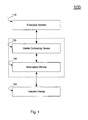
- an item selection system 100 includes an enterprise system 110, a mobile computing device 120, an interrogator device 130, and an indicator device 140.
- the enterprise system 110 is an inventory management system that stores and processes information related to items in inventory.
- the enterprise system 110 may be, for example, a standalone system or part of a larger business support system.
- the enterprise system 110 provides the mobile computing device 120 with information regarding items that need to be selected from the storage area. This information may include one or more entries in a list of items that need to be selected.
- the entries may include a type of item to select (for example, 1/4" phillips head screw), a quantity of the item (for example, 25), a location of the item (that is, stocking location), and an item identifier code. Other information such as specific item handling instructions may also be included.
- the mobile computing device 120 is a portable device that may be small enough to be carried by a user without occupying either of the hands of the user.
- the mobile computing device 120 receives item entries from the enterprise system 110. All of the item entries may be downloaded at one time and stored as a "picklist" (that is, a list of items to select or pick) in the memory of the mobile computing device 120.
- the picklist may list the item entries in a predetermined order associated with the location of the items in the storage area. For example, the order of the item entries may correspond to an item selection order that optimizes the efficiency of the path taken by the user as he or she picks items in the storage area.
- the picklist may be stored in the enterprise system 110, and item entries may be downloaded to the mobile computing device 120 one at a time from the enterprise system 110. In this case, the next item entry is not accessed until the current item entry has been processed (that is, the items corresponding to the entry have been picked).
- the item entries may also be provided to the mobile computing device 120 a single entry at a time in a predetermined order associated with the location of the items in the storage area.
- the mobile computing device 120 coordinates the selection of the items specified by the item entries. Specifically, the mobile computing device 120 sends an item identifier code to the interrogator device 130 and waits, in one implementation, for confirmation that item(s) associated with the item identifier code have been selected. Once such a confirmation is received, the mobile computing device 120 proceeds to the next item entry.
- the interrogator device 130 receives the item identifier code from the mobile computing device 120 and transmits a short-range activation signal in response.
- the interrogator device 130 transmits, in one implementation, a different activation signal for each item identifier code.
- the activation signal is used to activate an indicator device 140 associated with an item or items corresponding to the item identifier code.
- the interrogator device 130 may be integrated with the mobile computing device 120, as indicated by the dashed box in Fig. 1 .
- the storage area may be divided into subareas and/or storage containers that are associated with different item types.
- the storage location information of an item entry is mapped to a storage subarea and/or storage container by the enterprise system 110.
- the indicator devices 140 are arrayed within the storage area, each indicator device 140 corresponding to a different storage subarea or storage container that holds items of one or more specified item types.
- the indicator devices 140 are located in close physical proximity or attached to their respective storage subareas or storage containers.
- Each indicator device 140 responds to the activation signal of the interrogator device 130 if two conditions are met: (1) the interrogator device 130 is close enough to the indicator device and has direct line-of-sight in the case of infrared or visible light communication and that the short-range activation signal that reaches the indicator device is strong enough to be sensed by the indicator device; and (2) the item identifier code of the activation signal corresponds to the subarea or storage container associated with the indicator device 140. If both of these conditions are satisfied, the indicator device 140 sends an indication signal in response to the activation signal.
- the indication signal allows the user to determine the location of the item corresponding to the current item entry being processed.
- the user perceives the indication signal, proceeds to the indicated location (that is, storage container or storage subarea), and selects the item(s) in accordance with the item type and quantity specified by the item entry.
- the indicated location that is, storage container or storage subarea
- a confirmation is provided to the mobile computing device 140, and the mobile computing device 140 directs the interrogator device 130 to stop transmitting the activation signal.
- the mobile computing device 140 then proceeds to the next item entry.
- Each item entry is then similarly processed as described above until all items included in the picklist are selected.
- Fig. 2 shows an exemplary implementation 200 of the item selection system 100 of Fig. 1 .
- the functionality of the enterprise system 210, the mobile computing device 220, the interrogator device 230, and the indicator device 240 is analogous to that of, respectively, the enterprise system 110, the mobile computing device 120, the interrogator device 130, and the indicator device 140.
- the mobile computing device 220 may be a handheld personal digital assistant (PDA) 222 that includes a wireless LAN port 224, a display screen 226, a headset with microphone and earpiece 228, and a serial port 229.
- the enterprise system 210 provides the PDA 222 with one or more item entries in a list of items to select in the storage area (that is, a picklist).
- the PDA 222 receives these entries from the enterprise system 210 via the wireless LAN port 224.
- the item entries may be displayed or otherwise visually accessed all at once or one entry at a time via the display screen 226 of the PDA 222.
- the item entries may be enunciated to the user via voice using the headset with microphone and earpiece 228.
- the user may access and page through the item entries stored in the PDA 222 via, for example, a keyboard (not shown), via pressing the screen 226 with a stylus (not shown), or via voice commands using the headset with microphone and earpiece 228.
- the PDA 222 After downloading one or more item entries from the enterprise system 210, the PDA 222 processes the list of item entries one entry at a time in an order that may or may not be predetermined.
- the item selection process may be initiated, for example, manually by the user via PDA input (for example, keyboard, stylus, or voice), automatically and without user input by the PDA 222, or by the enterprise system 210.
- the PDA 222 and/or the enterprise system 210 associates each item entry in the list with an identifier code using the item storage subarea or item storage container information in the item entry.
- the mapping of item storage subareas or item storage containers to identifier codes is accomplished through a system setup process that takes place prior to the start of the item selection process. For ease of discussion, the system setup process is described after the description of the item selection process.
- the PDA 222 When processing an item entry, the PDA 222 sends an item identifier code to the interrogator device 230 using the serial port 229.
- the item identifier code corresponds to the storage subarea or storage container that holds the item types listed in the item entry.
- the interrogator device 230 is a badge 232 that may be secured to the clothes of the user and connected to the serial port 229 of the PDA 222 by a conductor (not shown).
- the badge 232 includes an infrared (IR) detector 234 and an IR transmitter 236.
- the badge 232 receives the identifier code from the mobile computing device 220 via the conductor (not shown) and transmits an IR activation signal using the IR transmitter 236.
- the identifier code is embedded in the IR activation signal. Transmitting codes in IR signals is a proven technology understood by one skilled in the art. This technology has been used, for example, in television remote controls.
- the IR activation signal is continuously sent out by the badge 232. Due to the short-range nature of the signal caused by attenuation of the signal over distance, an indicator device 240 will typically only detect the IR activation signal when the badge 232 is moved into close physical proximity (for example, 5-10 feet) to the indicator device 240. In addition, direct line-of-sight from the badge 232 to the indicator device 240 will normally be needed.
- the indicator device 240 determines whether the code received corresponds to its own code. If the transmitted code is associated with the code of the given indicator device 240, the indicator device 240 sends out an indicator signal that informs the user of the location of the indicator device 240. If the code is not associated with the code of the given indicator device, the indicator device 240 does not send an indicator signal.
- the short-range nature of the activation signal and the reqirement for direct-line-of-sight for the infrared signal allows multiple users with interrogator devices to select items simultaneously within the same storage area without confusion.
- Each user only activates indicator devices within their immediate physical vicinity (that is, the range of the short-range activation signal) and within their visual range since the IR badge is worn on the front of the user and radiates forward. Therefore, if the users are sufficiently separated from each other while selecting items in the storage area, each user will only respond to their own local indicator signals.
- the indicator signals directed at other users will not be near enough and in direct-line-of-sight to the user to cause confusion.
- This localized generation of indicator signals by the item selection systems 100, 200 decreases the cognitive steps required by the users to determine which indicator signals to respond to, and thus which items to pick, when multiple pickers are selecting items in the same storage area. Decreasing the cognitive steps that a user must perform when picking items improves the accuracy of the item selection process by reducing the opportunities for human error.
- the indicator device 240 may be battery-powered and fastened onto a storage subarea or storage container using, for example, a clip or a magnet.
- the indicator device 240 may include a base or a stand and be positioned on top or near a storage subarea or storage container.
- the indicator device 240 may also fit into a holder or similar type attachment device coupled to the storage subarea or storage container. Because the indicator devices 240 do not need to be connected by any wires, the location of the indicator devices 240 may be changed freely. This mobility offers the flexibility necessary for efficient use of the systems 100, 200 in, for example, a warehouse environment in which the location of storage containers and item storage areas may frequently change.
- the size of the indicator device is typically driven by the size and power of the required battery.
- each indicator device 240 is associated with a different identifier code that is mapped to the storage container on which the indicator device is attached.
- the location information of the item entry is used to determine the appropriate storage container identifier code.
- the mapping of storage containers to identifier codes occurs during a setup or configuration step prior to the beginning of the item selection process.
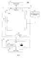
- Fig. 3 shows another implementation 300 of the item selection system 100 including an exemplary circuit schematic for an indicator device 340.
- the functionality of the enterprise system 310, the mobile computing device 320, the interrogator device 330, and the indicator device 340 is analogous to that of, respectively, the enterprise system 110, the mobile computing device 120, the interrogator device 130, and the indicator device 140.
- the indicator device 340 includes an IR-Detector 342, signal detection circuitry 344, optional proximity detection circuitry 346, optional battery level sense circuitry 348, a microprocessor 350, an optional numerical indicator 352, a light emitting diode (LED) 354, and an optional IR transmitter 356.
- LED light emitting diode
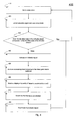
- Fig. 4 shows a process 400 used by the indicator device 340 to inform a user whether or not item(s) should be selected from an item storage container or item storage subarea associated with the indicator device 340.
- the indicator device 340 is in "sleep" mode prior to being activated by the IR activation signal of the interrogator device 330 (410). While in sleep mode, the microprocessor 350 of the indicator device 340 is placed into a low-power mode to conserve battery power. When an IR activation signal is detected by the IR detector 342, the signal detection circuitry 344 sends a "wake-up" signal to the microprocessor 350 that instructs the microprocessor 350 to leave the low-power mode and power-up completely (420).
- the IR detector 342 converts the IR activation signal into an electrical signal that includes the identifier code and sends the signal to the microprocessor 350.
- the microprocessor 350 analyzes the identifier code (430) and, if the identifier code does not correspond to the code associated with the indicator device 340, the microprocessor 350 deactivates by returning to sleep mode.
- the microprocessor 350 sends out a signal to activate the LED 354 (440), thereby generating an indicator signal.
- the LED 354 generates an indicator signal, for example, by being illuminated or by flashing.
- the microprocessor 350 may additionally send out an acknowledgement response to the interrogator device 330 using the optional transmitter 356 (450).
- the user may perceive the illuminated or flashing LED 354, for example, and proceed to the location of the indicator device 340. The user may then access the associated storage container or subarea to retrieve the item(s) described in the item entry being processed.
- the user may determine the quantity of items that should be selected from the storage subarea or storage container by looking at the display screen 326 of the PDA 322 or by receiving the quantity information vocally via the headset 328.
- the user may then input an item selection complete command into the PDA 322 upon completion of the selection of the quantity of items. This may be accomplished by manually interfacing with the PDA 322 using a stylus (not shown) or keyboard (not shown) or by vocally interfacing with the PDA 322 using the headset 328.
- the PDA 322 responds to the command by sending a confirmation signal to the badge 332.
- the badge 332 converts the confirmation signal into an IR signal using the IR transmitter 336 and transmits the confirmation signal to the indicator device 340. Alternatively, the badge 332 may simply stop transmitting the identifier code in response to the confirmation signal.
- the indicator device may enable a display of the quantity of items to be selected (460).
- the indicator device 340 may eliminate the need for the user to manually or vocally input the item selection complete command into the PDA 322 by using optional proximity detection circuitry 346 to sense each time an item is selected from the storage subarea or storage container.
- the proximity detection circuitry 346 senses or detects an arm reaching into the storage subarea or storage container.
- This circuitry may be magnetic (that is, a magneto resistive sensor), capacitive, or of another comparable technology type.
- a magneto resistive sensor may detect a small magnet or possibly just a metal watchband worn on the wrist of the user.
- the detection circuitry 346 senses each time the arm of the user with the attached metal watchband or magnet reaches into the storage subarea or storage container.
- the proximity detection circuitry 346 Upon the arm reaching into the storage subarea or storage container, the proximity detection circuitry 346 sends an "item selection detected” signal to the microprocessor 350. The microprocessor 350 then sends the "item selection detected” signal to the optional IR transmitter 356 which converts the signal into an IR signal and transmits it to the interrogator device 330.
- the badge 332 detects the "item selection detected” signal through its IR detector 334 and converts it into an electrical signal that is sent to the PDA 322.
- the PDA 322 then decrements the quantity of items corresponding to the item entry being processed by one.
- the indicator device 340 determines that the items are selected (470).
- the IR detector 342 of the indicator device may, for example, detect the confirmation signal from the badge 332, detect the absence of the identifier code signal from the badge 332, or determine that the quantity to be selected has been decremented to zero.
- the IR detector 342 then informs the microprocessor 350 (470).
- the microprocessor 350 then deactivates the LED 354 (480) and returns to sleep mode (410).
- the PDA 322 Upon the quantity decrementing to zero, the PDA 322 sends out a confirmation signal as discussed above and proceeds to the next item entry in the picklist.
- the user is directed to stop selecting items from the storage container or subarea vocally or visually by the PDA 322 using the headset 328 or the display screen 326, respectively.
- the user is directed to stop selecting items and proceed to the next item entry by simply perceiving the deactivation of the LED 354 (that is, it stops being illuminated or stops flashing).
- the use of the proximity detection circuitry 346 to keep track of item quantity information may require that the user select items in a specified manner to enable accurate detection by the circuitry 346. For example, the user may have to reach into the storage subarea or storage container a single time for each item selected despite, perhaps, the ability of the user to grab multiple items during a single reach-in.
- the indicator device 340 may also include the optional numerical indicator display 352 that displays the quantity of items that should be selected from the associated storage subarea or storage container.
- the numerical indicator display 352 may be, for example, a simple liquid crystal display (LCD) or a comparable lightweight, low-cost, low power display screen.
- the quantity information that is displayed on the numerical indicator display 352 may be received from the mobile computing device 320 via the interrogator device 330.
- the identifier code of the activation signal may include both an identifier that specifies a single indicator device 340 and an additional code that specifies the quantity of items that needs to be selected by the user.
- the microprocessor 350 of an indicator device 340 only examines the quantity portion of the code if the microprocessor 350 determines that the identifier is associated with the identifier of its indicator device 340. If the identifier portion of the identifier code does not correspond to the given indicator device 340, the indicator device 340 deactivates by returning to sleep mode.
- the numerical indicator 352 on the indicator device 340 may be directed by the microprocessor 350 to display the quantity information (460), simplifying the conveyance of this information to the user.
- the microprocessor 350 may direct the flash pattern of the LED 354 to indicate the quantity information.
- the optional proximity detection circuitry 346 may be used in conjunction with the optional numerical indicator display 352 to provide the user with a dynamic indicator of the number of items that should be selected from the storage subarea or storage container.
- the microprocessor 350 decrements the quantity of items that should be selected each time the proximity detection circuitry 346 detects the user reaching into the subarea or storage container.
- the flash pattern of the LED 354 may change in accordance with the decremented quantity.
- the numerical display 352 may decrement the displayed quantity in accordance with the decremented quantity.
- the microprocessor 350 Upon the quantity being decremented to zero, the microprocessor 350 then sends a single “selection complete” signal, thereby eliminating the need to continuously send out the "item selection detected” signals each time the user reaches into the storage subarea or storage container. Furthermore, upon sending the "selection complete signal,” the microprocessor 350 deactivates the LED 354 completely and returns to sleep mode, thereby eliminating the need for a separate confirmation signal.
- the indicator device 340 also includes the optional battery level sense circuitry 348.
- the battery level sense circuitry 348 detects the battery level of the indicator device 340. Specific circuit-level implementation of battery level sense circuitry 348 is understood by one skilled in the art, and is, therefore, not discussed further.
- the battery level sense circuitry 348 may be external to the microprocessor 350 or, alternatively, incorporated in the microprocessor 350.
- the microprocessor 350 communicates the battery level of the indicator device 350 to the user by sending a battery level signal using the IR transmitter 356.
- the IR detector 334 of the badge 332 detects the battery level signal, converts it into an electrical signal, and conveys it to the PDA 322.
- the PDA 322 may then provide a visual display on the display screen 326 to indicate the battery level or, additionally or alternatively, may provide an audible or vocal signal to the user using the headset 328.
- the audible signal may be as simple as a beep to the user indicating that the battery is low and needs to be replaced.
- the optional numerical readout indicator 352 may also be used to indicate the battery level of the battery in the indicator device 340.
- the microprocessor 350 may direct the readout indicator 352 to display a number or a figure representative of the battery level.
- the microprocessor 350 may provide the battery level information to the readout indicator 352 additionally or instead of the battery level signal that it provides to the badge 332 using the IR transmitter 356.
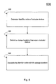
- Fig. 5 shows a process 500 for selecting an item using a system such as, for example, one of the systems 100, 200, 300.
- the process 500 includes accessing an item entry using a mobile computing device (510).
- the user walks into the storage area with the mobile computing device 120 and the interrogator device 130 attached to his or her person.
- the mobile computing device 120 may automatically access, or be manually instructed by the user to access, an entry in the current picklist to be processed.
- the entry may be accessed from the memory of the mobile computing device 120 after having downloaded all entries in the picklist from the enterprise system 110, or the entry may be accessed by downloading it individually and directly from the enterprise system 110.
- the item entry may provide the mobile computing device 120 with the item type, the item quantity, and the item identifier code of the storage container or storage subarea in which the item(s) described in the entry are located.
- the item entry may also provide other information such as actual stocking location and handling instructions for the item.
- the mobile computing device 120 instructs the interrogator device 130 to send out an activation signal associated with the item identifier code of the accessed item entry.
- the process 500 includes the user moving an interrogator device 230 to within a predetermined distance or range and within-line-of-sight of one or more indicator devices 140 (520).
- the user will follow a predetermined path in accordance with the layout of the storage area.
- the entries in the picklist may be ordered by the enterprise system 110 or possibly by the mobile computing device 120 in such a way as to allow the user to progress along the predetermined path while selecting items without ever having to backtrack.
- the interrogator device 130 is moved a predetermined distance (for example, 5-10 feet in the case of system 200) from one or more indicator devices 140, the short-range activation signal being transmitted by the interrogator device 130 is typically strong enough for the indicator devices 140 to activate and sense the signal.
- the indicator devices 140 are then able to determine whether the code embedded in the signal is associated with their own respective codes. If none of the indicator devices 140 detect their own code in the activation signal, they all deactivate and return to sleep mode. If one of the indicator devices 140 detects its code in the signal, it activates and sends an indicator signal to the user by, for example, illuminating or flashing an LED.
- the process 500 includes the user determining which indicator device 140 is activated in response to the interrogator device 130 based on the indicator signal (530). The user then proceeds to the location of the indicator device 140 that is activated.
- the process 500 includes the user selecting an item or items associated with the indicator device 140 that is activated (540).
- An indication of the quantity of items to select may be accessed from the mobile computing device 120 or from the indicator device 130 as discussed previously with respect to Figs. 2 and 3 .
- the process 500 includes deactivating the indicator device upon completion of item selection (550). Once the user completes selecting the items described by the item entry, the mobile computing device 120, the indicator device 130, and/or the user may deactivate the indicator device 130. The indicator device 130 then returns to low-power or sleep mode. The user may then proceed to the next item entry in the picklist and begin the process again (560).
- Fig. 6 shows a system setup process 600.
- the system setup process 600 precedes the item selection process 500 described above.
- the system setup process 600 begins by determining the identifier codes of the indicator devices 140 (610). This determination may be accomplished either manually or automatically.
- an operator determines the identifier codes by visually inspecting the identifier code associated with each indicator device 140. Note that the identifier code of each indicator device 140 may be printed on the indicator device 140 itself or may be included in the packaging materials of each indicator device 140.
- the operator need not determine the identifier code associated with each indicator device because the system 100 will automatically determine the identifier code during the mapping operation discussed below.
- the process 600 includes determining storage locations that require indicator devices 140 (620).
- the operator may use, for example, the mobile computing device 120 to access one or more storage location entries that correspond to storage locations that require indicator devices.
- the enterprise system 110, the mobile computing device 120, or the operator may determine the storage locations that require indicator devices 140.
- the process 600 includes associating the identifier codes of the indicator devices 140 with the storage locations (630).
- the operator approaches, in an order that may or may not be predetermined, one or more of the storage subareas or containers corresponding to the accessed storage location entries.
- the operator then attaches or adheres indicator devices 140 to the storage subareas or containers.
- the operator may manually associate or map the identifier code with the storage location entry by scanning the storage labels attached to each storage subarea or container using, for example, a barcode reader (not shown) and then manually inputting the identifier codes of the corresponding attached indicator devices 140.
- the storage location label may include some or all of the storage information stored in the enterprise system 110.
- the storage location label is typically affixed to the storage subarea or container.
- the mapping is then preferably sent to and stored in the enterprise system 110, but may also be stored in the mobile computing device 120.
- the operator does not manually input the identifier codes corresponding to the attached indicator devices 140. Rather, the indicator devices 140 may transmit the identifier codes to the interrogator device 130 in response to the interrogator device 130 sending a "general wakeup" code. The operator instructs the interrogator device 130 to send the "general wakeup" code and proceeds to each storage location corresponding to the accessed storage location entries. If the interrogator device 130 is brought close enough to a given indicator device 140, the identity code from that indicator device 140 may be uniquely detected and associated with that storage location. The operator then reads the storage label using, for example, a barcode reader and then the mobile computing device 120 automatically associates or maps the identifier code detected by the interrogator device 130 to that storage location. The mapping may then be stored in the mobile computing device 120 or sent to the enterprise system 110.
- the mobile computing device 120 may be a PDA, a laptop computer, a belt-mounted computer, or another computing device that is preferably designed to be portable and designed to minimally encumber a user's hands and mobility during operation.
- the mobile computing device 120 may also be a large and bulky computing device placed on a mobile cart.
- the mobile computing device 120 may be stationary but include a portable and mobile communications device that interfaces with the operator.
- the mobile computing device 120 may contain a cellular modem to communicate with the enterprise system 110. Alternatively, the mobile computing device 120 may communicate with the enterprise system 110 over a wide area radio network. The mobile computing device 120 may also operate offline, for example, through the use of a docking station.
- the mobile computing device 120 may allow the operator to choose the order in which the item entries in the selection list are processed.
- the mobile computing device 120 may, for example, allow an operator to choose the order by displaying a list of item entries on the display screen 226 of the PDA 220 and allowing the operator to select any entry in the list to process.
- the interrogator device 130 may be located at fixed points on the ceiling of the storage area.
- the mobile computing device 120 may activate the stationary interrogator devices 130 directly using a wireless communications port or indirectly via the enterprise system 110.
- One, more than one, or all of the stationary interrogator devices 130 may simultaneously send out a given identifier code when the mobile computing device 120 is processing an item entry.
- the stationary interrogator devices 130 may be positioned so as to allow the interrogator devices 130 to cover and activate some or all of the indicator devices 140 attached to some or all of the storage subareas and/or containers within the storage area.
- the interrogator device 130 and the mobile computing device 120 may be integrated in a single unit.
- a palmtop computing device or personal digital assistant may have a built-in IR communication feature.
- the interrogator device 130 may generate an activation signal using visible light, short-range radio (for example, by employing a short-range radio connectivity standard such as Bluetooth or IEEE 802.11), or other frequencies in the electromagnetic spectrum.
- the interrogator device 130 could also generate an activation signal using ultrasonic sound.
- the interrogator device 130 may send the activation signal at intervals of time that are regular or random in duration and that may or may not be predetermined.
- the interrogator device 130 may be able to transmit multiple activation signals, each of a different frequency. This allows certain indicator devices to be sensitive to some activation signals but not to others.
- the interrogator device 130 may be a portable device that may be attached to the clothes of an operator.
- the interrogator device may also be a handheld device that is worn around the wrist or neck.
- the numerical readout indicator 352 may additionally display the quantity of items selected and/or the total quantity of items currently in the storage subarea or storage container.
- the readout indicator 352 may dynamically receive the total item quantity information from the mobile computing device 320 via the interrogator device 330 each time a selection of items occurs.
- the readout indicator 352 may receive the total quantity of items in the storage subarea or storage container one time during the system setup process. Subsequent item selections from the storage bin or container may simply decrement this initial quantity. In such an implementation, the system setup process may also take place each time new items are stocked.
- the user may inform the indicator device 240 that the item selection is complete by manually pressing a button or manually inputting the information into the indicator device 240 using an attached manual interface (for example, a numerical indicator with an attached set of buttons or a single button).
- the microprocessor 250 may sense the user pressing the button and send a confirmation signal to the mobile computing device 220 via the interrogator device 230 prior to deactivating and returning the indicator device 240 to sleep mode.
- the manual interface may be a number pad that allows a user to manually input exactly how many items were selected.
- the microprocessor 250 may also provide this information to the mobile computing device 220.
- the item selection system 100 may be used as an item stocking system, for example, when automated stocking proves inefficient.
- the lists of items to select are replaced by lists of items to stock.
- the user Rather than selecting items from the storage containers or storage subareas, the user places items into the storage containers and storage subareas.
- the quantity in the item entry corresponds to the number of items to place into the corresponding storage area or storage container.
Landscapes
- Business, Economics & Management (AREA)
- Economics (AREA)
- Engineering & Computer Science (AREA)
- Marketing (AREA)
- Quality & Reliability (AREA)
- Finance (AREA)
- Entrepreneurship & Innovation (AREA)
- Human Resources & Organizations (AREA)
- Accounting & Taxation (AREA)
- Operations Research (AREA)
- Development Economics (AREA)
- Strategic Management (AREA)
- Tourism & Hospitality (AREA)
- Physics & Mathematics (AREA)
- General Business, Economics & Management (AREA)
- General Physics & Mathematics (AREA)
- Theoretical Computer Science (AREA)
- Warehouses Or Storage Devices (AREA)
Description
- Various implementations in this description relate generally to communications for identifying product locations and, more particularly, to infrared pick and pack systems.
- Manual picking and packing of goods in a warehouse or storage area environment typically involves a human picker traversing a warehouse or similar storage area and selecting, by hand, the goods corresponding to entries in a list. This list is commonly known as a picklist, and as each good in the picklist is selected, the picker typically packs it away for shipment or processing. To increase the accuracy and efficiency of this manual picking and packing of goods, pick-to-light systems have been developed. Typical pick-to-light systems provide pickers with a visual cue as to the location of the storage container or storage subarea that contains the goods corresponding to the entries in the picklist. For example, some pick-to-light systems include lights attached to or positioned near each storage subarea (for example, a shelf or designated floor space) or storage container (for example, a bin or a crate) in the storage area. The lights provide a visual cue to the picker by illuminating or flashing if the corresponding storage subarea or storage container contains the goods in the picklist. Other pick-to-light systems include a light emitting diode (LED) display associated with a set of storage containers or storage subareas. The LED display is typically an alphanumeric display that provides a picker with the coordinates of the containers or subareas that contain the goods in the picklist.
- Typical pick-to-light systems are limited in both flexibility and efficiency. First, typical pick-to-light systems tend to use fixed wiring to connect the lights or LED displays to their corresponding storage subareas or containers. The fixed wiring makes it difficult to rapidly change the location of goods in the storage area. For example, moving a set of crates from one location to another may require rewiring the lights associated with those crates or, alternatively, may require using entirely different lights and reprogramming the pick-to-light system accordingly. Second, typical pick-to-light systems tend to be ill-suited to support the simultaneous processing of multiple picklists in the same region of the warehouse. Typical systems may allow such simultaneous processing by introducing yet another cognitive step into the picking process. For example, different colored lights may be used for different picklists, but doing so forces a picker to identify not just which bin has an illuminated light near it but also requires that the picker further determine the color of the light and whether that color corresponds to his or her picklist. Introduction of this extra color determination cognitive step is undesirable in that it may lead to more errors and further decreases the accuracy of the manual picking process. The extremely high accuracy demands of manual picking and packing (for example, 99% accuracy) makes introduction of such an added margin of error undesirable.
-
US 5 880 449 A relates to a system and method for granting a customer visiting a store with personally associated prices for selected items. The customer receives a portable customer unit which communicates with a check in unit for establishing personal prices for selected items. - Thus, according to an aspect, it is a problem to provide an apparatus, a method and a system for requesting the location of items in a storage area which allow multiple users to select items simultaneously within the same storage area without confusion.
- This problem is solved by an apparatus having the features disclosed in
claim 1, a method having the features disclosed in claim 17 and a system having the features disclosed in claim 22. Preferred embodiments are defined in the dependent claims. - One implementation of a pick-and-pack system that provides both flexibility and efficiency includes battery-powered indicator devices that are each coupled to a given storage subarea or storage container within a storage area. The picker traverses the storage area while carrying a mobile computing device that is communicatively coupled to a mobile transmitter. The mobile computing device accesses item entries in a picklist and communicates each item entry to the mobile transmitter one at a time for processing.
- Continuing with this implementation, the mobile transmitter sends out a short-range infrared (IR) activation signal that corresponds to the item entry currently being processed. When the picker moves the mobile transmitter into physical proximity to an indicator device, the indicator device senses the IR activation signal and determines whether to respond to the activation signal. Each indicator device will respond only if the IR activation signal includes a specific item identifier code. The item identifier codes are different for each indicator device and are associated with the items stored within the storage subarea or storage container corresponding to that indicator device. The indicator device, therefore, only responds to the IR activation signal if the activation signal is brought physically near the indicator device (for example, to within a predetermined distance such as ten feet) and if the activation signal includes the item identifier code corresponding to that indicator device. The indicator device responds to the IR activation signal by illuminating a light that allows the picker to locate the storage container or storage subarea to which the indicator device is coupled and that will contain the items corresponding to the item entry being processed.
- In one general aspect, an apparatus for requesting the location of items in a storage area includes a mobile computing device and a transmitter. The mobile computing device accesses an entry in a list of items to be selected from item storage subareas within an item storage area. The entry is associated with an item identifier code corresponding to an item storage subarea. The transmitter is communicatively coupled to the mobile computing device and is able to transmit a short-range activation signal corresponding to the item identifier code. The short-range activation signal causes an indicator device associated with the item identifier code and in physical proximity to the short-range activation signal to transmit an indicator signal in response to the short-range activation signal that indicates the location of the corresponding item storage subarea. A proximity detection circuitry is provided for sensing each time an item is selected from the item storage subarea. Upon completion of item selection of the current item entry being processed, transmitting the activation signal is stopped.
- The mobile computing device may be a personal digital assistant (PDA), similar to devices made by Palm Corporation or iPAQ devices made by HP Corporation, laptop computer or a belt-mounted computer. The mobile computing device may receive the entry in the list of items from an enterprise system. The enterprise system may be an inventory management system. The mobile computing device may receive the entry from the enterprise system by using a docking station or over a wireless network. The wireless network may be a wireless local area network, a wide area radio network, or a cellular modem network. The mobile computing device may include a stationary component and a mobile component
- The activation signal may be an infrared signal, a short-range radio signal, or a visible light signal. The activation signal may include an embedded identifier code associated with the entry.
- The transmitter may be a mobile device or a portable device that is attached to the clothing of a person. The portable device may be a badge. The transmitter may be stationary and located at fixed points in the item storage area. The mobile computing device and the transmitter may be integrated in a single unit. The single unit may be a palmtop computing device or personal digital assistant with a built-in infrared communications feature.
- The transmitter may continuously send out the activation signal. The transmitter may send out the signal periodically. The period between transmissions may be fixed or random.
- In another general aspect, requesting the location of items in a storage area includes accessing an entry in a list of items to be selected from item storage subareas within an item storage area. The entry is associated with an item identifier code corresponding to an item storage subarea. A short-range activation signal corresponding to the item identifier code is transmitted. The short-range activation signal causes an indicator device associated with the item identifier code to transmit an indicator signal in response to the short-range activation signal that indicates the location of the corresponding item storage subarea. Each time an item is selected from the item storage subarea is sensed. Upon completion of item selection of the current item entry being processed, transmitting the activation signal is stopped.
- In another general aspect, an apparatus to indicate the location of items in a storage area includes a receiver, a processor, and a transmitter. The receiver receives a short-range activation signal sent by an interrogator device that is brought into close proximity to the receiver. The processor determines whether the short-range activation signal is associated with one or more items stored in an item storage subarea associated with the apparatus. The transmitter sends out an indicator signal in response to the activation signal upon determining that the activation signal is associated with one or more items stored in the item storage subarea.
- The apparatus may include a base and/or a fastener for attaching to the item storage subarea within the storage area. The apparatus may further include a numerical readout that displays the number of items selected from the item storage subarea or the total number of items in the item storage subarea.
- The apparatus may include a manual interface. The manual interface may allow the operator to inform the processor that item selection is complete or to manually input the number of items selected from the item storage subarea. The apparatus may include a battery and circuitry to detect the battery level. The apparatus may also include proximity detection circuitry that senses the number of times an operator selects items from the item storage subarea.
- The transmitter may send out the indicator signal in response to the activation signal if the interrogator device is within a certain approximate or predetermined distance (for example, within ten feet) of the apparatus. The transmitter may send out the indicator signal in response to detecting in the activation signal an embedded identifier code associated with the item storage subarea. The indicator signal may be visible light from a flashing or illuminated light emitting diode.
- In another general aspect, indicating the location of items in a storage area includes receiving a short-range activation signal sent by an interrogator device that is brought into close proximity to an indicator device. The indicator device is associated with an item storage subarea within an item storage area. It is determined whether the short-range activation signal is associated with one or more items stored in the item storage subarea. An indicator signal is transmitted in response to the activation signal upon determining that the activation signal is associated with one or more items stored in the item storage subarea. The indicator signal indicates the location of the item storage subarea.
- Transmitting the indicator signal in response to the activation signal may include transmitting the indicator signal only if the interrogator device is within a certain approximate distance of the indicator device (for example, within ten feet). The number of items selected from the storage subarea may be displayed using a numerical readout associated with the indicator device. The number of times an operator selects items from the storage subarea may be sensed using proximity detection circuitry. The indicator device may be attached to the item storage subarea.
- In another general aspect, a system for selecting items includes a mobile computing device, an interrogator device, and an indicator device. The mobile computing device is operable to receive an entry in a list of items to be selected from item storage subareas in an item storage area and to store the entry in a data storage. The interrogator device is operable to communicate with the mobile computing device and to send out an activation signal related to an item corresponding to the entry on the list. The indicator device is furthermore operable, upon completion of item selection of the current item entry being processed, to stop transmitting the activation signal. The system also comprises proximity detection circuitry for sensing each time an item is selected from the item storage subarea. The indicator device includes a fastener for attaching to an item storage subarea, a receiver for receiving the activation signal, and a transmitter for indicating the location of the item storage subarea by sending out an indicator signal in response to the activation signal if the item storage subarea is associated with the entry.
- The activation signal may be an infrared signal and may include an embedded identifier code associated with the entry. The mobile computing device may receive the entry in the list of items from an enterprise system. The enterprise system may comprise an inventory management system. The mobile computing device may receive the entry from the enterprise system over a wireless network. The interrogator device may comprise a portable device that may be attached to the person, and the portabled device may be a badge.
- In another general aspect, selecting items includes accessing an entry in a list of items using a mobile computing device and moving an interrogator device, that communicates with the mobile computing device, into physical proximity to an indicator device. It is determined whether the indicator device is associated with an item corresponding to the entry upon the interrogator device being moved a predetermined distance from the indicator device. An indicator device is activated if the indicator device is associated with the item. The location of the item corresponding to the entry is determined based on the activated indicator device.
- Determining whether the indicator device is associated with the item includes determining whether the indicator device is associated with the item based on an activation signal. The activation signal may be an infrared signal. The activation signal may include an embedded identifier code associated with the entry. Accessing the entry may include receiving the entry in the list of items from an enterprise system. The enterprise system may comprise an inventory management system. Receiving the entry from the enterprise system may include receiving the entry over a wireless network. The interrogator device may be a portable device that may be attached to the clothing of a person. The portable device may be a badge.
- Other features will be apparent from the description, the drawings, and the claims.
-
-
Fig. 1 is an exemplary block diagram of an item selection system. -
Fig. 2 is a block diagram of the item selection system ofFig. 1 showing an exemplary implementation of a mobile computing device and an interrogator device. -
Fig. 3 is a block diagram of the item selection system ofFig. 1 showing an exemplary implementation of an indicator device. -
Fig. 4 is an exemplary block diagram of a process depicting the operation of an indicator device. -
Fig. 5 is an exemplary block diagram of a process for selecting an item using the item selection system ofFig. 1 . -
Fig. 6 is an exemplary block diagram of a process to setup the item selection system ofFig. 1 - Referring to
Fig. 1 , anitem selection system 100 includes anenterprise system 110, amobile computing device 120, aninterrogator device 130, and anindicator device 140. Theenterprise system 110 is an inventory management system that stores and processes information related to items in inventory. Theenterprise system 110 may be, for example, a standalone system or part of a larger business support system. Theenterprise system 110 provides themobile computing device 120 with information regarding items that need to be selected from the storage area. This information may include one or more entries in a list of items that need to be selected. The entries may include a type of item to select (for example, 1/4" phillips head screw), a quantity of the item (for example, 25), a location of the item (that is, stocking location), and an item identifier code. Other information such as specific item handling instructions may also be included. - The
mobile computing device 120 is a portable device that may be small enough to be carried by a user without occupying either of the hands of the user. Themobile computing device 120 receives item entries from theenterprise system 110. All of the item entries may be downloaded at one time and stored as a "picklist" (that is, a list of items to select or pick) in the memory of themobile computing device 120. The picklist may list the item entries in a predetermined order associated with the location of the items in the storage area. For example, the order of the item entries may correspond to an item selection order that optimizes the efficiency of the path taken by the user as he or she picks items in the storage area. - Alternatively, the picklist may be stored in the
enterprise system 110, and item entries may be downloaded to themobile computing device 120 one at a time from theenterprise system 110. In this case, the next item entry is not accessed until the current item entry has been processed (that is, the items corresponding to the entry have been picked). The item entries may also be provided to the mobile computing device 120 a single entry at a time in a predetermined order associated with the location of the items in the storage area. - The
mobile computing device 120 coordinates the selection of the items specified by the item entries. Specifically, themobile computing device 120 sends an item identifier code to theinterrogator device 130 and waits, in one implementation, for confirmation that item(s) associated with the item identifier code have been selected. Once such a confirmation is received, themobile computing device 120 proceeds to the next item entry. - The
interrogator device 130 receives the item identifier code from themobile computing device 120 and transmits a short-range activation signal in response. Theinterrogator device 130 transmits, in one implementation, a different activation signal for each item identifier code. The activation signal is used to activate anindicator device 140 associated with an item or items corresponding to the item identifier code. Theinterrogator device 130 may be integrated with themobile computing device 120, as indicated by the dashed box inFig. 1 . - The storage area may be divided into subareas and/or storage containers that are associated with different item types. The storage location information of an item entry is mapped to a storage subarea and/or storage container by the
enterprise system 110. Theindicator devices 140 are arrayed within the storage area, eachindicator device 140 corresponding to a different storage subarea or storage container that holds items of one or more specified item types. Theindicator devices 140 are located in close physical proximity or attached to their respective storage subareas or storage containers. - Each
indicator device 140 responds to the activation signal of theinterrogator device 130 if two conditions are met: (1) theinterrogator device 130 is close enough to the indicator device and has direct line-of-sight in the case of infrared or visible light communication and that the short-range activation signal that reaches the indicator device is strong enough to be sensed by the indicator device; and (2) the item identifier code of the activation signal corresponds to the subarea or storage container associated with theindicator device 140. If both of these conditions are satisfied, theindicator device 140 sends an indication signal in response to the activation signal. - The indication signal allows the user to determine the location of the item corresponding to the current item entry being processed. The user perceives the indication signal, proceeds to the indicated location (that is, storage container or storage subarea), and selects the item(s) in accordance with the item type and quantity specified by the item entry. Once the selection of the item(s) is complete, a confirmation is provided to the
mobile computing device 140, and themobile computing device 140 directs theinterrogator device 130 to stop transmitting the activation signal. Themobile computing device 140 then proceeds to the next item entry. Each item entry is then similarly processed as described above until all items included in the picklist are selected. -
Fig. 2 shows anexemplary implementation 200 of theitem selection system 100 ofFig. 1 . The functionality of theenterprise system 210, themobile computing device 220, theinterrogator device 230, and theindicator device 240 is analogous to that of, respectively, theenterprise system 110, themobile computing device 120, theinterrogator device 130, and theindicator device 140. - The
mobile computing device 220 may be a handheld personal digital assistant (PDA) 222 that includes awireless LAN port 224, adisplay screen 226, a headset with microphone andearpiece 228, and aserial port 229. Theenterprise system 210 provides thePDA 222 with one or more item entries in a list of items to select in the storage area (that is, a picklist). ThePDA 222 receives these entries from theenterprise system 210 via thewireless LAN port 224. The item entries may be displayed or otherwise visually accessed all at once or one entry at a time via thedisplay screen 226 of thePDA 222. Alternatively or additionally, the item entries may be enunciated to the user via voice using the headset with microphone andearpiece 228. The user may access and page through the item entries stored in thePDA 222 via, for example, a keyboard (not shown), via pressing thescreen 226 with a stylus (not shown), or via voice commands using the headset with microphone andearpiece 228. - After downloading one or more item entries from the
enterprise system 210, thePDA 222 processes the list of item entries one entry at a time in an order that may or may not be predetermined. The item selection process may be initiated, for example, manually by the user via PDA input (for example, keyboard, stylus, or voice), automatically and without user input by thePDA 222, or by theenterprise system 210. - The
PDA 222 and/or theenterprise system 210 associates each item entry in the list with an identifier code using the item storage subarea or item storage container information in the item entry. The mapping of item storage subareas or item storage containers to identifier codes is accomplished through a system setup process that takes place prior to the start of the item selection process. For ease of discussion, the system setup process is described after the description of the item selection process. - When processing an item entry, the
PDA 222 sends an item identifier code to theinterrogator device 230 using theserial port 229. The item identifier code corresponds to the storage subarea or storage container that holds the item types listed in the item entry. - The
interrogator device 230 is abadge 232 that may be secured to the clothes of the user and connected to theserial port 229 of thePDA 222 by a conductor (not shown). Thebadge 232 includes an infrared (IR)detector 234 and anIR transmitter 236. - The
badge 232 receives the identifier code from themobile computing device 220 via the conductor (not shown) and transmits an IR activation signal using theIR transmitter 236. The identifier code is embedded in the IR activation signal. Transmitting codes in IR signals is a proven technology understood by one skilled in the art. This technology has been used, for example, in television remote controls. - The IR activation signal is continuously sent out by the
badge 232. Due to the short-range nature of the signal caused by attenuation of the signal over distance, anindicator device 240 will typically only detect the IR activation signal when thebadge 232 is moved into close physical proximity (for example, 5-10 feet) to theindicator device 240. In addition, direct line-of-sight from thebadge 232 to theindicator device 240 will normally be needed. Theindicator device 240 then determines whether the code received corresponds to its own code. If the transmitted code is associated with the code of the givenindicator device 240, theindicator device 240 sends out an indicator signal that informs the user of the location of theindicator device 240. If the code is not associated with the code of the given indicator device, theindicator device 240 does not send an indicator signal. - The short-range nature of the activation signal and the reqirement for direct-line-of-sight for the infrared signal allows multiple users with interrogator devices to select items simultaneously within the same storage area without confusion. Each user only activates indicator devices within their immediate physical vicinity (that is, the range of the short-range activation signal) and within their visual range since the IR badge is worn on the front of the user and radiates forward. Therefore, if the users are sufficiently separated from each other while selecting items in the storage area, each user will only respond to their own local indicator signals. The indicator signals directed at other users will not be near enough and in direct-line-of-sight to the user to cause confusion. This localized generation of indicator signals by the
item selection systems - The
indicator device 240 may be battery-powered and fastened onto a storage subarea or storage container using, for example, a clip or a magnet. Alternatively, theindicator device 240 may include a base or a stand and be positioned on top or near a storage subarea or storage container. Theindicator device 240 may also fit into a holder or similar type attachment device coupled to the storage subarea or storage container. Because theindicator devices 240 do not need to be connected by any wires, the location of theindicator devices 240 may be changed freely. This mobility offers the flexibility necessary for efficient use of thesystems - In this implementation, each
indicator device 240 is associated with a different identifier code that is mapped to the storage container on which the indicator device is attached. When an item entry is being processed, the location information of the item entry is used to determine the appropriate storage container identifier code. The mapping of storage containers to identifier codes occurs during a setup or configuration step prior to the beginning of the item selection process. -
Fig. 3 shows anotherimplementation 300 of theitem selection system 100 including an exemplary circuit schematic for anindicator device 340. The functionality of theenterprise system 310, themobile computing device 320, theinterrogator device 330, and theindicator device 340 is analogous to that of, respectively, theenterprise system 110, themobile computing device 120, theinterrogator device 130, and theindicator device 140. Theindicator device 340 includes an IR-Detector 342,signal detection circuitry 344, optionalproximity detection circuitry 346, optional batterylevel sense circuitry 348, amicroprocessor 350, an optionalnumerical indicator 352, a light emitting diode (LED) 354, and anoptional IR transmitter 356. -
Fig. 4 shows aprocess 400 used by theindicator device 340 to inform a user whether or not item(s) should be selected from an item storage container or item storage subarea associated with theindicator device 340. Theindicator device 340 is in "sleep" mode prior to being activated by the IR activation signal of the interrogator device 330 (410). While in sleep mode, themicroprocessor 350 of theindicator device 340 is placed into a low-power mode to conserve battery power. When an IR activation signal is detected by theIR detector 342, thesignal detection circuitry 344 sends a "wake-up" signal to themicroprocessor 350 that instructs themicroprocessor 350 to leave the low-power mode and power-up completely (420). - The
IR detector 342 converts the IR activation signal into an electrical signal that includes the identifier code and sends the signal to themicroprocessor 350. Themicroprocessor 350 analyzes the identifier code (430) and, if the identifier code does not correspond to the code associated with theindicator device 340, themicroprocessor 350 deactivates by returning to sleep mode. - If, however, the code does correspond to the code associated with the
indicator device 340, themicroprocessor 350 sends out a signal to activate the LED 354 (440), thereby generating an indicator signal. TheLED 354 generates an indicator signal, for example, by being illuminated or by flashing. Themicroprocessor 350 may additionally send out an acknowledgement response to theinterrogator device 330 using the optional transmitter 356 (450). - The user may perceive the illuminated or flashing
LED 354, for example, and proceed to the location of theindicator device 340. The user may then access the associated storage container or subarea to retrieve the item(s) described in the item entry being processed. - The user may determine the quantity of items that should be selected from the storage subarea or storage container by looking at the display screen 326 of the PDA 322 or by receiving the quantity information vocally via the headset 328. The user may then input an item selection complete command into the PDA 322 upon completion of the selection of the quantity of items. This may be accomplished by manually interfacing with the PDA 322 using a stylus (not shown) or keyboard (not shown) or by vocally interfacing with the PDA 322 using the headset 328. The PDA 322 responds to the command by sending a confirmation signal to the badge 332.
- The badge 332 converts the confirmation signal into an IR signal using the IR transmitter 336 and transmits the confirmation signal to the
indicator device 340. Alternatively, the badge 332 may simply stop transmitting the identifier code in response to the confirmation signal. - In various implementations, the indicator device may enable a display of the quantity of items to be selected (460). In one such implementation, the
indicator device 340 may eliminate the need for the user to manually or vocally input the item selection complete command into the PDA 322 by using optionalproximity detection circuitry 346 to sense each time an item is selected from the storage subarea or storage container. Theproximity detection circuitry 346 senses or detects an arm reaching into the storage subarea or storage container. This circuitry may be magnetic (that is, a magneto resistive sensor), capacitive, or of another comparable technology type. For example, a magneto resistive sensor may detect a small magnet or possibly just a metal watchband worn on the wrist of the user. Thedetection circuitry 346 senses each time the arm of the user with the attached metal watchband or magnet reaches into the storage subarea or storage container. - Upon the arm reaching into the storage subarea or storage container, the
proximity detection circuitry 346 sends an "item selection detected" signal to themicroprocessor 350. Themicroprocessor 350 then sends the "item selection detected" signal to theoptional IR transmitter 356 which converts the signal into an IR signal and transmits it to theinterrogator device 330. - The badge 332 detects the "item selection detected" signal through its IR detector 334 and converts it into an electrical signal that is sent to the PDA 322. The PDA 322 then decrements the quantity of items corresponding to the item entry being processed by one.
- The
indicator device 340 determines that the items are selected (470). TheIR detector 342 of the indicator device may, for example, detect the confirmation signal from the badge 332, detect the absence of the identifier code signal from the badge 332, or determine that the quantity to be selected has been decremented to zero. TheIR detector 342 then informs the microprocessor 350 (470). Themicroprocessor 350 then deactivates the LED 354 (480) and returns to sleep mode (410). - Upon the quantity decrementing to zero, the PDA 322 sends out a confirmation signal as discussed above and proceeds to the next item entry in the picklist. The user is directed to stop selecting items from the storage container or subarea vocally or visually by the PDA 322 using the headset 328 or the display screen 326, respectively. Alternatively or additionally, the user is directed to stop selecting items and proceed to the next item entry by simply perceiving the deactivation of the LED 354 (that is, it stops being illuminated or stops flashing).
- The use of the
proximity detection circuitry 346 to keep track of item quantity information may require that the user select items in a specified manner to enable accurate detection by thecircuitry 346. For example, the user may have to reach into the storage subarea or storage container a single time for each item selected despite, perhaps, the ability of the user to grab multiple items during a single reach-in. - The
indicator device 340 may also include the optionalnumerical indicator display 352 that displays the quantity of items that should be selected from the associated storage subarea or storage container. Thenumerical indicator display 352 may be, for example, a simple liquid crystal display (LCD) or a comparable lightweight, low-cost, low power display screen. - The quantity information that is displayed on the
numerical indicator display 352 may be received from themobile computing device 320 via theinterrogator device 330. In this implementation, the identifier code of the activation signal may include both an identifier that specifies asingle indicator device 340 and an additional code that specifies the quantity of items that needs to be selected by the user. Themicroprocessor 350 of anindicator device 340 only examines the quantity portion of the code if themicroprocessor 350 determines that the identifier is associated with the identifier of itsindicator device 340. If the identifier portion of the identifier code does not correspond to the givenindicator device 340, theindicator device 340 deactivates by returning to sleep mode. - When the
indicator device 340 is activated and receives the quantity information for the item entry that is being processed, thenumerical indicator 352 on theindicator device 340 may be directed by themicroprocessor 350 to display the quantity information (460), simplifying the conveyance of this information to the user. Alternatively or additionally, themicroprocessor 350 may direct the flash pattern of theLED 354 to indicate the quantity information. - The optional
proximity detection circuitry 346 may be used in conjunction with the optionalnumerical indicator display 352 to provide the user with a dynamic indicator of the number of items that should be selected from the storage subarea or storage container. Themicroprocessor 350 decrements the quantity of items that should be selected each time theproximity detection circuitry 346 detects the user reaching into the subarea or storage container. The flash pattern of theLED 354 may change in accordance with the decremented quantity. Similarly, thenumerical display 352 may decrement the displayed quantity in accordance with the decremented quantity. - Upon the quantity being decremented to zero, the
microprocessor 350 then sends a single "selection complete" signal, thereby eliminating the need to continuously send out the "item selection detected" signals each time the user reaches into the storage subarea or storage container. Furthermore, upon sending the "selection complete signal," themicroprocessor 350 deactivates theLED 354 completely and returns to sleep mode, thereby eliminating the need for a separate confirmation signal. - The
indicator device 340 also includes the optional batterylevel sense circuitry 348. The batterylevel sense circuitry 348 detects the battery level of theindicator device 340. Specific circuit-level implementation of batterylevel sense circuitry 348 is understood by one skilled in the art, and is, therefore, not discussed further. The batterylevel sense circuitry 348 may be external to themicroprocessor 350 or, alternatively, incorporated in themicroprocessor 350. - The
microprocessor 350 communicates the battery level of theindicator device 350 to the user by sending a battery level signal using theIR transmitter 356. The IR detector 334 of the badge 332 detects the battery level signal, converts it into an electrical signal, and conveys it to the PDA 322. The PDA 322 may then provide a visual display on the display screen 326 to indicate the battery level or, additionally or alternatively, may provide an audible or vocal signal to the user using the headset 328. The audible signal may be as simple as a beep to the user indicating that the battery is low and needs to be replaced. - The optional
numerical readout indicator 352 may also be used to indicate the battery level of the battery in theindicator device 340. In this case, themicroprocessor 350 may direct thereadout indicator 352 to display a number or a figure representative of the battery level. Themicroprocessor 350 may provide the battery level information to thereadout indicator 352 additionally or instead of the battery level signal that it provides to the badge 332 using theIR transmitter 356. -
Fig. 5 shows aprocess 500 for selecting an item using a system such as, for example, one of thesystems process 500 includes accessing an item entry using a mobile computing device (510). The user walks into the storage area with themobile computing device 120 and theinterrogator device 130 attached to his or her person. Themobile computing device 120 may automatically access, or be manually instructed by the user to access, an entry in the current picklist to be processed. - The entry may be accessed from the memory of the
mobile computing device 120 after having downloaded all entries in the picklist from theenterprise system 110, or the entry may be accessed by downloading it individually and directly from theenterprise system 110. The item entry may provide themobile computing device 120 with the item type, the item quantity, and the item identifier code of the storage container or storage subarea in which the item(s) described in the entry are located. The item entry may also provide other information such as actual stocking location and handling instructions for the item. Themobile computing device 120 instructs theinterrogator device 130 to send out an activation signal associated with the item identifier code of the accessed item entry. - The
process 500 includes the user moving aninterrogator device 230 to within a predetermined distance or range and within-line-of-sight of one or more indicator devices 140 (520). Typically, the user will follow a predetermined path in accordance with the layout of the storage area. The entries in the picklist may be ordered by theenterprise system 110 or possibly by themobile computing device 120 in such a way as to allow the user to progress along the predetermined path while selecting items without ever having to backtrack. When theinterrogator device 130 is moved a predetermined distance (for example, 5-10 feet in the case of system 200) from one ormore indicator devices 140, the short-range activation signal being transmitted by theinterrogator device 130 is typically strong enough for theindicator devices 140 to activate and sense the signal. Theindicator devices 140 are then able to determine whether the code embedded in the signal is associated with their own respective codes. If none of theindicator devices 140 detect their own code in the activation signal, they all deactivate and return to sleep mode. If one of theindicator devices 140 detects its code in the signal, it activates and sends an indicator signal to the user by, for example, illuminating or flashing an LED. - The
process 500 includes the user determining whichindicator device 140 is activated in response to theinterrogator device 130 based on the indicator signal (530). The user then proceeds to the location of theindicator device 140 that is activated. - The
process 500 includes the user selecting an item or items associated with theindicator device 140 that is activated (540). An indication of the quantity of items to select may be accessed from themobile computing device 120 or from theindicator device 130 as discussed previously with respect toFigs. 2 and3 . - The
process 500 includes deactivating the indicator device upon completion of item selection (550). Once the user completes selecting the items described by the item entry, themobile computing device 120, theindicator device 130, and/or the user may deactivate theindicator device 130. Theindicator device 130 then returns to low-power or sleep mode. The user may then proceed to the next item entry in the picklist and begin the process again (560). -
Fig. 6 shows asystem setup process 600. Thesystem setup process 600 precedes theitem selection process 500 described above. Thesystem setup process 600 begins by determining the identifier codes of the indicator devices 140 (610). This determination may be accomplished either manually or automatically. In a manual setup, an operator determines the identifier codes by visually inspecting the identifier code associated with eachindicator device 140. Note that the identifier code of eachindicator device 140 may be printed on theindicator device 140 itself or may be included in the packaging materials of eachindicator device 140. In an automatic setup, the operator need not determine the identifier code associated with each indicator device because thesystem 100 will automatically determine the identifier code during the mapping operation discussed below. - The
process 600 includes determining storage locations that require indicator devices 140 (620). In both manual and automatic setups, the operator may use, for example, themobile computing device 120 to access one or more storage location entries that correspond to storage locations that require indicator devices. Theenterprise system 110, themobile computing device 120, or the operator may determine the storage locations that requireindicator devices 140. - The
process 600 includes associating the identifier codes of theindicator devices 140 with the storage locations (630). The operator approaches, in an order that may or may not be predetermined, one or more of the storage subareas or containers corresponding to the accessed storage location entries. The operator then attaches or adheresindicator devices 140 to the storage subareas or containers. - In a manual setup, the operator may manually associate or map the identifier code with the storage location entry by scanning the storage labels attached to each storage subarea or container using, for example, a barcode reader (not shown) and then manually inputting the identifier codes of the corresponding attached
indicator devices 140. The storage location label may include some or all of the storage information stored in theenterprise system 110. The storage location label is typically affixed to the storage subarea or container. The mapping is then preferably sent to and stored in theenterprise system 110, but may also be stored in themobile computing device 120. - In an automatic setup, the operator does not manually input the identifier codes corresponding to the attached
indicator devices 140. Rather, theindicator devices 140 may transmit the identifier codes to theinterrogator device 130 in response to theinterrogator device 130 sending a "general wakeup" code. The operator instructs theinterrogator device 130 to send the "general wakeup" code and proceeds to each storage location corresponding to the accessed storage location entries. If theinterrogator device 130 is brought close enough to a givenindicator device 140, the identity code from thatindicator device 140 may be uniquely detected and associated with that storage location. The operator then reads the storage label using, for example, a barcode reader and then themobile computing device 120 automatically associates or maps the identifier code detected by theinterrogator device 130 to that storage location. The mapping may then be stored in themobile computing device 120 or sent to theenterprise system 110. - Other implementations are possible. For example, the
mobile computing device 120 may be a PDA, a laptop computer, a belt-mounted computer, or another computing device that is preferably designed to be portable and designed to minimally encumber a user's hands and mobility during operation. Themobile computing device 120, however, may also be a large and bulky computing device placed on a mobile cart. Alternatively, themobile computing device 120 may be stationary but include a portable and mobile communications device that interfaces with the operator. - The
mobile computing device 120 may contain a cellular modem to communicate with theenterprise system 110. Alternatively, themobile computing device 120 may communicate with theenterprise system 110 over a wide area radio network. Themobile computing device 120 may also operate offline, for example, through the use of a docking station. - The
mobile computing device 120 may allow the operator to choose the order in which the item entries in the selection list are processed. Themobile computing device 120 may, for example, allow an operator to choose the order by displaying a list of item entries on thedisplay screen 226 of thePDA 220 and allowing the operator to select any entry in the list to process. - The
interrogator device 130 may be located at fixed points on the ceiling of the storage area. In such an implementation, themobile computing device 120 may activate thestationary interrogator devices 130 directly using a wireless communications port or indirectly via theenterprise system 110. One, more than one, or all of thestationary interrogator devices 130 may simultaneously send out a given identifier code when themobile computing device 120 is processing an item entry. Thestationary interrogator devices 130 may be positioned so as to allow theinterrogator devices 130 to cover and activate some or all of theindicator devices 140 attached to some or all of the storage subareas and/or containers within the storage area. - The
interrogator device 130 and themobile computing device 120 may be integrated in a single unit. As an example, a palmtop computing device or personal digital assistant may have a built-in IR communication feature. - The
interrogator device 130 may generate an activation signal using visible light, short-range radio (for example, by employing a short-range radio connectivity standard such as Bluetooth or IEEE 802.11), or other frequencies in the electromagnetic spectrum. Theinterrogator device 130 could also generate an activation signal using ultrasonic sound. - The
interrogator device 130 may send the activation signal at intervals of time that are regular or random in duration and that may or may not be predetermined. Theinterrogator device 130 may be able to transmit multiple activation signals, each of a different frequency. This allows certain indicator devices to be sensitive to some activation signals but not to others. - The
interrogator device 130 may be a portable device that may be attached to the clothes of an operator. The interrogator device may also be a handheld device that is worn around the wrist or neck. - The
numerical readout indicator 352 may additionally display the quantity of items selected and/or the total quantity of items currently in the storage subarea or storage container. Thereadout indicator 352 may dynamically receive the total item quantity information from themobile computing device 320 via theinterrogator device 330 each time a selection of items occurs. Alternatively or additionally, thereadout indicator 352 may receive the total quantity of items in the storage subarea or storage container one time during the system setup process. Subsequent item selections from the storage bin or container may simply decrement this initial quantity. In such an implementation, the system setup process may also take place each time new items are stocked. - The user rather than the
PDA 222 may inform theindicator device 240 that the item selection is complete by manually pressing a button or manually inputting the information into theindicator device 240 using an attached manual interface (for example, a numerical indicator with an attached set of buttons or a single button). The microprocessor 250 may sense the user pressing the button and send a confirmation signal to themobile computing device 220 via theinterrogator device 230 prior to deactivating and returning theindicator device 240 to sleep mode. The manual interface may be a number pad that allows a user to manually input exactly how many items were selected. The microprocessor 250 may also provide this information to themobile computing device 220. - The
item selection system 100 may be used as an item stocking system, for example, when automated stocking proves inefficient. In such an implementation, the lists of items to select are replaced by lists of items to stock. Rather than selecting items from the storage containers or storage subareas, the user places items into the storage containers and storage subareas. The quantity in the item entry corresponds to the number of items to place into the corresponding storage area or storage container.
Claims (23)
- An apparatus for requesting the location of items in a storage area, the apparatus comprising:a mobile computing device (120; 320) for accessing an entry in a list of items to be selected from item storage subareas within an item storage area, the entry being associated with an item identifier code corresponding to an item storage subarea, an entry containing the quantity of the item;an indicator device (140, 240) including a proximity detection circuitry (346) for sensing each time an item is selected from the item storage subarea and a microprocessor (350); anda transmitter communicatively coupled to the mobile computing device (120; 320) forwherein
transmitting a short-range activation signal corresponding to the item identifier code, the short-range activation signal causing the indicator device (140; 240) associated with the item identifier code that is mapped to the item storage subarea on which the indicator device (140, 240) is attached and in physical proximity to the short-range activation signal to transmit an indicator signal in response to the short-range activation signal that indicates the location of the corresponding item storage subarea, and ;
said proximity detection circuitry (346) is suitable for sending an item selection detected signal via said microprocessor (350) to said transmitter;
said transmitter is suitable for sending said item selection detected signal to said mobile computing device;
said mobile computing device is suitable for decrementing the quantity of items corresponding to the item entry being processed by one upon receipt of said item selection detected signal, and upon the quantity decrementing to zero sending out a confirmation signal to the transmitter;
stopping transmitting the activation signal upon receipt of the confirmation signal. - The apparatus of claim 1 wherein the activation signal comprises an infrared signal.
- The apparatus of claim 2 wherein the activation signal includes an embedded identifier code associated with the entry.
- The apparatus of claim 1 wherein the transmitter comprises a mobile transmitter.
- The apparatus of claim 1 wherein the mobile computing device (120; 320) receives the entry in the list of items from an enterprise system (110; 310).
- The apparatus of claim 5 wherein the enterprise system (110; 310) comprises an inventory management system.
- The apparatus of claim 5 wherein the mobile computing device (120; 320) receives the entry from the enterprise system (110; 310) by using a docking station.
- The apparatus of claim 5 wherein the mobile computing device (120; 320) receives the entry from the enterprise system (110; 310) over a wireless network.
- The apparatus of claim 1 wherein the activation signal comprises a short-range radio signal.
- The apparatus of claim 1 wherein the activation signal comprises a visible light signal.
- The apparatus of claim 1 wherein the transmitter comprises a portable device that may be attached to the clothing of a person.
- The apparatus of claim 11 wherein the portable device comprises a badge.
- The apparatus of claim 1 wherein the transmitter is stationary and located at fixed points in the item storage area.
- The apparatus of claim 1 wherein the mobile computing device (120; 320) and the transmitter are integrated in a single unit.
- The apparatus of claim 1 wherein the mobile transmitter is operable to continuously transmit the activation signal.
- The apparatus of claim 1 wherein the mobile transmitter is operable to transmit the activation signal periodically.
- A method for requesting the location of items in a storage area, the method comprising:accessing (510) an entry in a list of items to be selected from item storage subareas within an item storage area by a mobile computing device (120; 320), the entry being associated with an item identifier code corresponding to an item storage subarea, an entry containing the quantity of the item;transmitting a short-range activation signal corresponding to the item identifier code by a transmitter, the short-range activation signal causing an indicator device (140) associated with the item identifier code, that is mapped to the item storage subarea on which the indicator device (140, 240) is attached, to transmit an indicator signal in response to the short-range activation signal that indicates the location of the corresponding item storage subarea;sensing each time an item is selected from the item storage subarea by a proximity detection circuitry (346) of the indicator device (140, 240); andsending an item selection detected signal by said proximity detection circuitry (346) via a microprocessor (350) included in said indicator device (140, 240) to said transmitter;sending said item selection detected signal by said transmitter to said mobile computing device;by said mobile computing device, decrementing the quantity of items corresponding to the item entry being processed by one upon receipt of said item selection detected signal, and upon the quantity decrementing to zero sending out a confirmation signal to the transmitter;stopping transmitting the activation signal by said transmitter upon receipt of the confirmation signal.
- The method of claim 17 wherein accessing the entry includes accessing the entry using a mobile computing device (120; 320).
- The method of claim 17 wherein transmitting a short-range activation signal includes transmitting a short-range signal using a transmitter.
- The method of claim 19 wherein the transmitter comprises a mobile transmitter.
- The method of claim 20 wherein the mobile transmitter is communicatively coupled to a mobile computing device (120; 320) used to access the entry.
- A system for selecting items, the system comprising
a mobile computing device (120; 320) operable to receive an entry in a list of items to be selected from item storage subareas in an item storage area, and to store the entry in a data storage, wherein the entry is associated with an item identifier code corresponding to an item storage subarea, an entry containing the quantity of the item;
an interrogator device (130; 330) operable to communicate with the mobile computing device (120; 320) and to send out an activation signal related to an item corresponding to the entry on the list and, upon completion of item selection of the current item entry being processed, to stop transmitting the activation signal;
an indicator device (140; 240) associated with the item identifier code, that is mapped to the item storage subarea on which the indicator device (140, 240) is attached and including a fastener for attaching to an item storage subarea, a receiver for receiving the activation signal, and a transmitter for indicating the location of the item storage subarea by sending out an indicator signal in response to the activation signal if the item storage subarea is associated with the entry; and
said indicator device (140; 240) including a proximity detection circuitry (346) for sensing each time an item is selected from the item storage subarea and a microprocessor (350)
said proximity detection circuitry (346) is suitable for sending an item selection detected signal via said microprocessor (350) to said transmitter;
said interrogator device (130; 330) is suitable for sending said item selection detected signal to said mobile computing device:said mobile commuting device is suitable for decrementing the quantity of items corresponding to the item entry being processed by one upon receipt of said item selection detected signal, and upon the quantity decrementing to zero sending out a confirmation signal to the transmitter;said interrogator device (130; 330) is suitable for
stopping transmitting the activation signal upon receipt of the confirmation signal. - The system of claim 22 wherein the interrogator device (130; 330) comprises a portable device that may be attached to the clothing of a person.
Applications Claiming Priority (5)
| Application Number | Priority Date | Filing Date | Title |
|---|---|---|---|
| US38377202P | 2002-05-30 | 2002-05-30 | |
| US383772P | 2002-05-30 | ||
| US10/259,790 US7155166B2 (en) | 2002-05-30 | 2002-09-30 | Wireless pick-and-pack system |
| US259790 | 2002-09-30 | ||
| PCT/US2003/017294 WO2003102847A1 (en) | 2002-05-30 | 2003-05-30 | Wireless pick-and-pack system |
Publications (2)
| Publication Number | Publication Date |
|---|---|
| EP1514207A1 EP1514207A1 (en) | 2005-03-16 |
| EP1514207B1 true EP1514207B1 (en) | 2012-12-19 |
Family
ID=29714904
Family Applications (1)
| Application Number | Title | Priority Date | Filing Date |
|---|---|---|---|
| EP03734330A Expired - Lifetime EP1514207B1 (en) | 2002-05-30 | 2003-05-30 | Wireless pick-and-pack system |
Country Status (5)
| Country | Link |
|---|---|
| US (1) | US7155166B2 (en) |
| EP (1) | EP1514207B1 (en) |
| JP (1) | JP2005528306A (en) |
| AU (1) | AU2003239920A1 (en) |
| WO (1) | WO2003102847A1 (en) |
Families Citing this family (29)
| Publication number | Priority date | Publication date | Assignee | Title |
|---|---|---|---|---|
| US20050240498A1 (en) * | 2004-04-22 | 2005-10-27 | Arnold Thaler | Product verification and activation system, method and apparatus |
| KR100585705B1 (en) * | 2004-12-02 | 2006-06-07 | 엘지전자 주식회사 | How to display the battery level of the Bluetooth headset |
| US7706778B2 (en) | 2005-04-05 | 2010-04-27 | Assa Abloy Ab | System and method for remotely assigning and revoking access credentials using a near field communication equipped mobile phone |
| US9985950B2 (en) | 2006-08-09 | 2018-05-29 | Assa Abloy Ab | Method and apparatus for making a decision on a card |
| US8074271B2 (en) * | 2006-08-09 | 2011-12-06 | Assa Abloy Ab | Method and apparatus for making a decision on a card |
| DE102007026480A1 (en) * | 2007-06-05 | 2008-12-11 | Fraunhofer-Gesellschaft zur Förderung der angewandten Forschung e.V. | Method for commissioning of goods, involves attaching mobile data processing units addressed on data processing system in commissioning controlling system to identify current collection containers |
| JP4987586B2 (en) * | 2007-06-22 | 2012-07-25 | 株式会社東芝 | Information processing apparatus and control method |
| CN101345554B (en) * | 2008-08-19 | 2012-06-27 | 华为终端有限公司 | Method, equipment and system for displaying electric quantity of Bluetooth equipment on Bluetooth mobile phone |
| DE102008046501B4 (en) * | 2008-09-09 | 2024-06-06 | Bizerba SE & Co. KG | Control device |
| US20110035247A1 (en) * | 2009-08-04 | 2011-02-10 | United Parcel Service Of America | Systems, methods, apparatuses, and computer program products for determining productivity associated with retrieving items in a warehouse |
| DE102009042144C5 (en) * | 2009-09-14 | 2019-07-04 | Ssi Schäfer Automation Gmbh | User-configurable control system for a picking warehouse and method for configuring the order-picking warehouse |
| EP2403277B1 (en) * | 2010-07-01 | 2016-12-14 | Alcatel Lucent | Detector |
| US8599018B2 (en) | 2010-11-18 | 2013-12-03 | Yael Debra Kellen | Alarm system having an indicator light that is external to an enclosed space for indicating the time elapsed since an intrusion into the enclosed space and method for installing the alarm system |
| US8624735B2 (en) | 2010-11-18 | 2014-01-07 | Yael Debra Kellen | Alarm system having an indicator light that is external to an enclosed space for indicating the specific location of an intrusion into the enclosed space and a method for installing the alarm system |
| DE102011109373A1 (en) * | 2011-08-04 | 2012-04-19 | K & U Printware Gmbh | Automatic vending machine e.g. beverage dispenser has collection container that receives returned goods according to goods identification result, and data processing unit connected to user interface based on identification result |
| CN103781402A (en) * | 2011-09-09 | 2014-05-07 | 德尔格医疗系统有限公司 | Systems and methods of cable management |
| US9656804B2 (en) * | 2011-12-20 | 2017-05-23 | Hoj Engineering & Sales Co., Inc. | Warehouse management system |
| US9754238B2 (en) * | 2011-12-20 | 2017-09-05 | Hoj Engineering & Sales Co., Inc. | Warehouse management system |
| CA2874456C (en) * | 2012-05-22 | 2018-07-03 | Wynright Corporation | System, method, and apparatus for picking-and-putting product |
| US9179246B2 (en) | 2013-01-29 | 2015-11-03 | International Business Machines Corporation | Direction coupling discrimination of networked exchanges |
| EP3031031A4 (en) * | 2014-04-11 | 2016-06-22 | Pricer Ab | METHOD AND SYSTEM FOR POSITIONING ELECTRONIC SHELF LABEL |
| CN106575212B (en) | 2014-07-23 | 2019-08-27 | 德马泰克公司 | Laser Mobile Placement Wall |
| NL1041380B1 (en) * | 2015-06-29 | 2017-01-23 | Johan Pierre Van Den Berk Freddy | Method resp. system for signaling to a user products that satisfy a selection criterion set by the user. |
| DE102015222793A1 (en) * | 2015-11-18 | 2017-05-18 | Fraunhofer-Gesellschaft zur Förderung der angewandten Forschung e.V. | Logistics system for manual picking |
| US10600109B2 (en) | 2016-01-11 | 2020-03-24 | Honeywell International Inc. | Tag for order fulfillment |
| JP6619657B2 (en) * | 2016-01-29 | 2019-12-11 | 株式会社日立製作所 | Work support system, gate and work support method |
| FR3050053B1 (en) * | 2016-04-06 | 2018-05-04 | L'air Liquide, Societe Anonyme Pour L'etude Et L'exploitation Des Procedes Georges Claude | METHOD OF CALCULATING THE AUTONOMY OF A GAS DISTRIBUTION SET |
| US10140895B2 (en) | 2017-01-10 | 2018-11-27 | Walmart Apollo, Llc | Task-indicating shelf |
| US10699511B2 (en) | 2018-03-14 | 2020-06-30 | Indie Llc | Systems and methods for performing automated fastener selection |
Citations (1)
| Publication number | Priority date | Publication date | Assignee | Title |
|---|---|---|---|---|
| US6105004A (en) * | 1996-04-18 | 2000-08-15 | Eldat Communication, Ltd. | Product monitoring system particularly useful in merchandising and inventory control |
Family Cites Families (8)
| Publication number | Priority date | Publication date | Assignee | Title |
|---|---|---|---|---|
| US3908800A (en) * | 1974-04-12 | 1975-09-30 | Scope Inc | Item selecting system |
| FR2631721A1 (en) | 1988-05-19 | 1989-11-24 | Socty Sarl | Electronic system for collecting products stored on pallets without using location and pickup parts lists |
| IL114965A (en) * | 1995-08-17 | 2001-01-11 | Eldat Comm Ltd | System and method for providing a store customer with personally associated prices for selected items |
| IL118686A0 (en) * | 1996-06-19 | 1996-10-16 | Eldat Communication Ltd | Navigation system using changeable signs |
| US6084512A (en) * | 1998-10-02 | 2000-07-04 | Lucent Technologies, Inc. | Method and apparatus for electronic labeling and localizing |
| WO2000077704A2 (en) | 1999-06-11 | 2000-12-21 | Creative Golf Designs, Inc. | Inventory control system |
| US6464142B1 (en) * | 1999-10-29 | 2002-10-15 | Si/Baker, Inc. | Automated will call system |
| US6496121B2 (en) * | 2001-02-14 | 2002-12-17 | Ncr Corporation | Methods and apparatus for an electronic shelf label communication system |
-
2002
- 2002-09-30 US US10/259,790 patent/US7155166B2/en not_active Expired - Lifetime
-
2003
- 2003-05-30 JP JP2004509859A patent/JP2005528306A/en active Pending
- 2003-05-30 EP EP03734330A patent/EP1514207B1/en not_active Expired - Lifetime
- 2003-05-30 WO PCT/US2003/017294 patent/WO2003102847A1/en not_active Ceased
- 2003-05-30 AU AU2003239920A patent/AU2003239920A1/en not_active Abandoned
Patent Citations (1)
| Publication number | Priority date | Publication date | Assignee | Title |
|---|---|---|---|---|
| US6105004A (en) * | 1996-04-18 | 2000-08-15 | Eldat Communication, Ltd. | Product monitoring system particularly useful in merchandising and inventory control |
Also Published As
| Publication number | Publication date |
|---|---|
| US7155166B2 (en) | 2006-12-26 |
| AU2003239920A1 (en) | 2003-12-19 |
| US20040203409A1 (en) | 2004-10-14 |
| WO2003102847A1 (en) | 2003-12-11 |
| JP2005528306A (en) | 2005-09-22 |
| EP1514207A1 (en) | 2005-03-16 |
Similar Documents
| Publication | Publication Date | Title |
|---|---|---|
| EP1514207B1 (en) | Wireless pick-and-pack system | |
| US12073456B2 (en) | Techniques for filling orders | |
| US9900061B1 (en) | Wearable passive scanning device | |
| US12315002B2 (en) | Techniques for filling orders | |
| US7757947B2 (en) | R.F.I.D. enabled storage bin and method for tracking inventory | |
| US8577759B2 (en) | Inventory control system process | |
| US12557889B2 (en) | Article-identification-and-location device systems and methods of using same | |
| KR100872501B1 (en) | Mobile transponder reading device | |
| US20160104109A1 (en) | Identifying inventory items in a storage facility | |
| CA2673025A1 (en) | System and method for communicating status information | |
| US12367366B2 (en) | Article-identification-and-location device systems and methods of using same | |
| JP2011129000A (en) | System and method for managing work | |
| WO2001073710A1 (en) | Information managing system | |
| US9030323B2 (en) | Method and apparatus for detecting position | |
| US12029333B2 (en) | Product management system, product management apparatus, and display zone communication apparatus | |
| US20220156794A1 (en) | Product management system, product management apparatus, and tool communication apparatus | |
| US9530034B2 (en) | Apparatus comprising a reader and method for controlling the reader | |
| KR20110018608A (en) | Store management systems | |
| WO2011109655A1 (en) | Inventory control system process | |
| KR100782340B1 (en) | Route providing device and method using RDF / WSN | |
| WO2023018678A1 (en) | Article-identification-and-location device and systems and methods of using same | |
| JP2007084283A (en) | Information providing device and information collecting terminal device | |
| CN115099255A (en) | Commodity pickup detection method and equipment and computer readable storage medium | |
| TW201003527A (en) | Object searching device with image displaying function |
Legal Events
| Date | Code | Title | Description |
|---|---|---|---|
| PUAI | Public reference made under article 153(3) epc to a published international application that has entered the european phase |
Free format text: ORIGINAL CODE: 0009012 |
|
| 17P | Request for examination filed |
Effective date: 20041230 |
|
| AK | Designated contracting states |
Kind code of ref document: A1 Designated state(s): AT BE BG CH CY CZ DE DK EE ES FI FR GB GR HU IE IT LI LU MC NL PT RO SE SI SK TR |
|
| AX | Request for extension of the european patent |
Extension state: AL LT LV MK |
|
| DAX | Request for extension of the european patent (deleted) | ||
| RBV | Designated contracting states (corrected) |
Designated state(s): DE FR GB |
|
| RAP1 | Party data changed (applicant data changed or rights of an application transferred) |
Owner name: SAP AG |
|
| 17Q | First examination report despatched |
Effective date: 20100201 |
|
| REG | Reference to a national code |
Ref country code: DE Ref legal event code: R079 Ref document number: 60342899 Country of ref document: DE Free format text: PREVIOUS MAIN CLASS: G06F0017600000 Ipc: G06Q0010080000 |
|
| GRAP | Despatch of communication of intention to grant a patent |
Free format text: ORIGINAL CODE: EPIDOSNIGR1 |
|
| RIC1 | Information provided on ipc code assigned before grant |
Ipc: G06Q 10/08 20120101AFI20120627BHEP |
|
| GRAS | Grant fee paid |
Free format text: ORIGINAL CODE: EPIDOSNIGR3 |
|
| GRAA | (expected) grant |
Free format text: ORIGINAL CODE: 0009210 |
|
| AK | Designated contracting states |
Kind code of ref document: B1 Designated state(s): DE FR GB |
|
| REG | Reference to a national code |
Ref country code: GB Ref legal event code: FG4D |
|
| REG | Reference to a national code |
Ref country code: DE Ref legal event code: R096 Ref document number: 60342899 Country of ref document: DE Effective date: 20130307 |
|
| PLBE | No opposition filed within time limit |
Free format text: ORIGINAL CODE: 0009261 |
|
| STAA | Information on the status of an ep patent application or granted ep patent |
Free format text: STATUS: NO OPPOSITION FILED WITHIN TIME LIMIT |
|
| 26N | No opposition filed |
Effective date: 20130920 |
|
| REG | Reference to a national code |
Ref country code: DE Ref legal event code: R097 Ref document number: 60342899 Country of ref document: DE Effective date: 20130920 |
|
| REG | Reference to a national code |
Ref country code: DE Ref legal event code: R082 Ref document number: 60342899 Country of ref document: DE Representative=s name: MUELLER-BORE & PARTNER PATENTANWAELTE PARTG MB, DE |
|
| REG | Reference to a national code |
Ref country code: DE Ref legal event code: R081 Ref document number: 60342899 Country of ref document: DE Owner name: SAP SE, DE Free format text: FORMER OWNER: SAP AG, 69190 WALLDORF, DE Effective date: 20141210 Ref country code: DE Ref legal event code: R081 Ref document number: 60342899 Country of ref document: DE Owner name: SAP SE, DE Free format text: FORMER OWNER: SAP AG, 69190 WALLDORF, DE Effective date: 20121219 Ref country code: DE Ref legal event code: R082 Ref document number: 60342899 Country of ref document: DE Representative=s name: MUELLER-BORE & PARTNER PATENTANWAELTE PARTG MB, DE Effective date: 20141210 |
|
| REG | Reference to a national code |
Ref country code: FR Ref legal event code: PLFP Year of fee payment: 14 |
|
| REG | Reference to a national code |
Ref country code: FR Ref legal event code: PLFP Year of fee payment: 15 |
|
| REG | Reference to a national code |
Ref country code: FR Ref legal event code: PLFP Year of fee payment: 16 |
|
| PGFP | Annual fee paid to national office [announced via postgrant information from national office to epo] |
Ref country code: GB Payment date: 20220519 Year of fee payment: 20 Ref country code: FR Payment date: 20220523 Year of fee payment: 20 Ref country code: DE Payment date: 20220519 Year of fee payment: 20 |
|
| REG | Reference to a national code |
Ref country code: DE Ref legal event code: R071 Ref document number: 60342899 Country of ref document: DE |
|
| REG | Reference to a national code |
Ref country code: GB Ref legal event code: PE20 Expiry date: 20230529 |
|
| PG25 | Lapsed in a contracting state [announced via postgrant information from national office to epo] |
Ref country code: GB Free format text: LAPSE BECAUSE OF EXPIRATION OF PROTECTION Effective date: 20230529 |