EP1514036B1 - Coupling arrangement - Google Patents
Coupling arrangement Download PDFInfo
- Publication number
- EP1514036B1 EP1514036B1 EP03725185A EP03725185A EP1514036B1 EP 1514036 B1 EP1514036 B1 EP 1514036B1 EP 03725185 A EP03725185 A EP 03725185A EP 03725185 A EP03725185 A EP 03725185A EP 1514036 B1 EP1514036 B1 EP 1514036B1
- Authority
- EP
- European Patent Office
- Prior art keywords
- force transmission
- engaging force
- lever
- arrangement
- housing
- Prior art date
- Legal status (The legal status is an assumption and is not a legal conclusion. Google has not performed a legal analysis and makes no representation as to the accuracy of the status listed.)
- Expired - Lifetime
Links
- 230000008878 coupling Effects 0.000 title claims abstract description 28
- 238000010168 coupling process Methods 0.000 title claims abstract description 28
- 238000005859 coupling reaction Methods 0.000 title claims abstract description 28
- 230000005540 biological transmission Effects 0.000 claims abstract description 91
- 239000000463 material Substances 0.000 claims description 11
- 238000006243 chemical reaction Methods 0.000 claims description 4
- 230000015572 biosynthetic process Effects 0.000 claims description 2
- 230000009977 dual effect Effects 0.000 description 5
- 239000002184 metal Substances 0.000 description 4
- 238000010276 construction Methods 0.000 description 3
- 230000000694 effects Effects 0.000 description 3
- 230000004927 fusion Effects 0.000 description 2
- 230000007246 mechanism Effects 0.000 description 2
- 230000002093 peripheral effect Effects 0.000 description 2
- 230000009471 action Effects 0.000 description 1
- 230000000712 assembly Effects 0.000 description 1
- 238000000429 assembly Methods 0.000 description 1
- 238000005452 bending Methods 0.000 description 1
- 238000005266 casting Methods 0.000 description 1
- 239000002131 composite material Substances 0.000 description 1
- 238000006073 displacement reaction Methods 0.000 description 1
- 238000004049 embossing Methods 0.000 description 1
- 230000004048 modification Effects 0.000 description 1
- 238000012986 modification Methods 0.000 description 1
- 210000000056 organ Anatomy 0.000 description 1
- 238000004080 punching Methods 0.000 description 1
- 230000009467 reduction Effects 0.000 description 1
- 238000005096 rolling process Methods 0.000 description 1
- 238000012384 transportation and delivery Methods 0.000 description 1
Images



Classifications
-
- F—MECHANICAL ENGINEERING; LIGHTING; HEATING; WEAPONS; BLASTING
- F16—ENGINEERING ELEMENTS AND UNITS; GENERAL MEASURES FOR PRODUCING AND MAINTAINING EFFECTIVE FUNCTIONING OF MACHINES OR INSTALLATIONS; THERMAL INSULATION IN GENERAL
- F16D—COUPLINGS FOR TRANSMITTING ROTATION; CLUTCHES; BRAKES
- F16D13/00—Friction clutches
- F16D13/58—Details
- F16D13/583—Diaphragm-springs, e.g. Belleville
-
- F—MECHANICAL ENGINEERING; LIGHTING; HEATING; WEAPONS; BLASTING
- F16—ENGINEERING ELEMENTS AND UNITS; GENERAL MEASURES FOR PRODUCING AND MAINTAINING EFFECTIVE FUNCTIONING OF MACHINES OR INSTALLATIONS; THERMAL INSULATION IN GENERAL
- F16D—COUPLINGS FOR TRANSMITTING ROTATION; CLUTCHES; BRAKES
- F16D13/00—Friction clutches
- F16D13/58—Details
- F16D13/70—Pressure members, e.g. pressure plates, for clutch-plates or lamellae; Guiding arrangements for pressure members
- F16D13/71—Pressure members, e.g. pressure plates, for clutch-plates or lamellae; Guiding arrangements for pressure members in which the clutching pressure is produced by springs only
Definitions
- the present invention relates to a clutch assembly comprising at least one to be pressed towards an abutment assembly pressure plate and an engagement force transmission lever assembly which is acted upon to transmit an engagement force on the pressure plate and is supported on a housing and initiates an engagement force in an engagement force transmission element.
- Such a coupling arrangement is known, for example, from EP 1 134 447.
- a clutch arrangement comprising at least one pressure plate which can be pressed in the direction of an abutment arrangement and an engagement force transmission lever arrangement which can be acted upon to transmit an engagement force to the pressure plate and is supported on a housing and an engagement force in initiates an engagement force transmission element.
- the engagement force transmission lever assembly is formed integrally with the engagement force transmission element.
- a very stable structure which is also very easy to realize, for example, by forming sheet metal blanks, can be obtained by forming the engagement force transmission element cup-shaped and by forming the engagement force transmission lever arrangement in a bottom area of the cup-shaped engagement force transmission element.
- the engagement force transmission lever arrangement it is possible for the engagement force transmission lever arrangement to comprise a plurality of circumferentially successive about an axis of rotation and of a ring-like region of the Engagement force transmission element comprises radially inwardly extending lever portions.
- the object mentioned at the outset is achieved by a coupling arrangement comprising at least one pressure plate to be pressed in the direction of an abutment arrangement, wherein the pressure plate is arranged in a housing and with this substantially rotationally fixed and with respect thereto in the direction of a rotation axis is displaceably coupled, and a Ein Wegkraftübertragungshebelan extract which acts on the pressure plate for transmitting an engagement force and initiates a reaction force into the housing.
- the invention further provides that the engagement force transmission lever assembly is integrally formed with the housing.
- the housing is pot-shaped and that the engagement force transmission lever assembly is formed in a bottom portion of the pot-like housing, wherein advantageously then may be further provided that the engagement force transmission lever assembly a plurality of circumferentially successive and of a ring-like Area of the housing radially inwardly extending lever sections comprises.
- a clutch arrangement comprising at least one pressure plate which can be pressed in the direction of an abutment arrangement and an engagement force transmission lever arrangement which can be acted upon to transmit an engagement force to the pressure plate and is supported on a housing and one Engagement force in an engagement force transmission element or a pressure plate initiates.
- the engagement force transmission lever arrangement is of annular design and comprises a plurality of lever sections which follow each other in the circumferential direction about an axis of rotation and extend essentially radially, which are connected to one another in a connection region.
- the engagement force transmission element in the circumferential direction has successive and each engaging between two lever portions of Ein Wegkraftübertragungshebelanssen coupling portions and that the lever portions and the coupling portions are coupled by a ring-like coupling element for power transmission.
- the connecting region can connect the lever sections in their radially inner region, in their radially central region or in their radially outer region.
- the lever sections have material recesses in a region close to the connection region. Furthermore, it can be provided that the lever sections are widened from one another in the circumferential direction separating material recesses in at least one radial region.
- lever sections above all have to transmit comparatively large forces even in clutch arrangements used in commercial vehicles, it may be advantageous if an approximately radially extending rib-like formation is formed on at least one lever section.
- the clutch assembly according to the invention may for example be designed such that it comprises a pressure plate on both sides of the abutment arrangement that a first Ein Wegkraftübertragungshebelan ever is supported on a housing and a first of the pressure plates toward the abutment assembly to act and that a second Ein Wegkraftschreibungshebelan ever an engaging force on the second the pressure plates over at least one engagement force transmission element transmits.
- FIGS. 1 and 2 A first embodiment of a clutch assembly 10 constructed in the form of a dual clutch according to the invention is shown in FIGS. 1 and 2.
- This clutch assembly 10 includes a generally designated 12 housing assembly, which in turn comprises two housing components 14, 16.
- the housing component 14 produced as a casting is connected in its radially outer, approximately axially extending region to a driving element 18, which in turn can be coupled to a drive shaft, a flywheel, for example, a dual mass flywheel.
- a flywheel for example, a dual mass flywheel.
- the housing part 16 forms an intermediate plate.
- the housing part 16 is preferably formed as a sheet metal forming part and is fixedly connected in its radially outer region with the housing part 14 by a plurality of bolts 22.
- a first pressure plate 24 is arranged such that it is coupled, for example via tangential leaf springs o. The like. With the housing part 16 substantially non-rotatably, in the direction of a rotation axis, however, is displaced. Between the pressure plate 24 and the intermediate plate 20 is a first clutch plate 26 with its friction linings 28. In order to bias the first pressure plate 24 in the direction of the intermediate plate 20 and thereby firmly clamp the clutch disc 26, a first Ein Wegkraftauertragungshebelanssen 30 is provided. A possible constructive structure of this engaging force transmission lever assembly will be described in detail below with reference to other embodiments.
- this transmission lever assembly includes a plurality of circumferentially successive lever portions 32, which are supported in the illustrated example in its radially outer end portion 34 on the housing part 16, for example via a wire ring 36 in a radially middle, ie further inside area applied to the pressure plate 24 and in a radially inner, not shown in Fig. 1 area can be acted upon by a Ein Wegkrafter Wegungsmechanismus so that they deliver, essentially without their own significant contribution to power, with appropriate Ein Wegkrafter Wegung with its radially central portion 38, the Anpresslatte 24 and thereby responsively supported on the housing part 16.
- a second coupling portion 42 essentially comprises a second pressure plate 44, the rotationally fixed in the housing part 14, but with respect to this axially is worn displaced. Between this second pressure plate 44 and the intermediate plate 20 is a second clutch disc 46 with its friction linings 48.
- An annular Einschkraftschreibtragungselement acts on the pressure plate 44, for example via a Verschl constitunachstellvorraum 52. This engagement force transmission element 50 is not shown in Fig.
- this engagement force transmission element 50 is then coupled to the engagement force transmission element 50 by the aforementioned connection elements. With its cup bottom region 58, this engagement force transmission element 54 simultaneously forms a second engagement force transmission lever assembly 60. Also, this comprises, as seen in Fig.
- FIGS. 3 and 4 show an alternative embodiment of a clutch arrangement according to the invention.
- Components which correspond to the above-described components in terms of design are denoted by the same reference numeral with the addition of an appendix "a".
- the basic construction of the dual-clutch arrangement 10a shown in FIGS. 3 and 4 is the same as described above with reference to FIG Figures 1 and 2 described construction corresponds, so that reference may be made to the relevant embodiments.
- the engagement force transmission lever assembly 30a of the first clutch portion 40a is now not provided as an independent assembly, but is fused to another member, namely the housing member 16a. This in turn is pot-shaped and now forms with its bottom portion 76a, the engagement force transmission lever assembly 30a.
- the individual lever sections 32a thus enclose radially outwardly an annular region 78a of the bottom region 76a, which annular region 78a now in turn forms a connection region 74a for the individual lever sections 32a.
- the lever sections 32a act on the pressure plate 24a directly or possibly via a wear adjusting device in their radially middle or further inward region and are formed in their radially inner region 80a for application by an engagement force transmission mechanism.
- a substantially cup-shaped support housing 82a is provided in order to be able to support the engagement force transmission lever arrangement 60a of the second coupling region 42 responsively to an axially fixed assembly. This is pushed with its outer wall portion 84a over the corresponding outer wall portion 86a of the housing part 16a and held there preferably under a press fit. The wire ring 66a, which is acted on by the engagement force transmission lever arrangement 60a for reaction-force generation, is now supported on the outside of this support housing 82a.
- FIGS. 5 to 12 show further variants of double clutches according to the invention.
- components which correspond to components described above in terms of structure and function are denoted by the same reference numeral with the addition of an appendix "b".
- the basic structure of the dual clutch assembly is as described above.
- the engagement force transmission lever arrangement 60b of the second clutch area 42b here comprises a plurality of lever sections 62b, which are now fixedly coupled to one another in their radially inner area 68b by an annular connecting area 74b. From there, the circumferentially spaced lever sections 62b extend radially outward.
- the engagement force transmitting member 54b has in its axial end portion a plurality of tongue-like coupling portions 90b positioned so as to engage circumferentially between each pair of lever portions 62b. This then results in the recognizable in Fig. 5 configuration in which the lever portions 62b and the coupling portions 90b overlap each other.
- a trained as a wire ring coupling ring 92b is radially outside of the coupling portions 90b, so that it also overlaps in the radial direction with the radially outer ends of the lever portions 62b and thus is axially supported on these.
- the coupling portions 90b are rolled radially outwardly after the axial advancement of the engagement force transmission lever assembly 62b and substantially also bringing the coupling ring 92b axially forward following the final operation in assembling the clutch assembly 10b, thus providing a strong coupling integrity between the assembly Engagement force transmission element 54b and the Engaging power transmission lever assembly 60b is obtained.
- the lever sections 62b of the engagement force transmission lever arrangement 60b are supported in their radially outer region over the annular bottom region 64b of the again substantially cup-shaped engagement force transmission element 54b at the latter.
- a support portion 94b may be provided to the engagement force transmitting member 54b.
- an engagement force transmission lever arrangement 60b is shown, which is configured essentially in the manner of an annular disc and again has the lever sections 62b in the circumferential direction successively. These are in their radially inner portion 68b again integrally connected to each other by the annular connecting portion 74b, it being understood that, as in the embodiments described above, this transmission lever assembly 60b is preferably generated by punching from a sheet metal blank. By material recesses 70b, which are extended in their radially inner, adjoining the connecting portion 74b end portion 98b, the individual lever portions 60b are separated from each other.
- the lever sections 60b are provided with a low material thickness, which supports their decoupling in terms of power. Nevertheless, however, the lever sections 60b For the engagement force transmission to be made sufficiently rigid, at least some of these can have rib-like recesses or elevations 100b extending in the radial direction and generated, for example, by embossing or deformation.
- the material recesses 70b are widened in a radially outward region 102b, which may also be advantageous in particular, the engagement force transmission lever arrangement 60b by, for example, in FIG. 5 recognizable bolt elements 104b on the housing or other Define support.
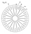
- FIG. 12 shows an embodiment of a ring-disk-shaped engagement force transmission lever arrangement 60b, in which now the individual lever sections 62b are coupled together in their radially outer region 106b by an annular peripheral connection region 74b. Close to this connection region 74b, the individual lever sections 62b each have essentially elongated slot-like recesses 110b between two material recesses 70b which separate the lever sections 62b.
- the individual lever sections 62b are divided in their region of the connection to the connection region 74b into individual section segments of smaller circumferential extent, so that a further decoupling of the individual lever sections 62b from each other can be achieved here.
- connection portion 74b can be varied with respect to the illustrated embodiments.
Landscapes
- Engineering & Computer Science (AREA)
- General Engineering & Computer Science (AREA)
- Mechanical Engineering (AREA)
- Mechanical Operated Clutches (AREA)
- Control Of Motors That Do Not Use Commutators (AREA)
- Table Devices Or Equipment (AREA)
Abstract
Description
Die vorliegende Erfindung betrifft eine Kupplungsanordnung, umfassend wenigstens eine in Richtung auf eine Widerlageranordnung zu pressbare Anpressplatte sowie eine Einrückkraftübertragungshebelanordnung, welche zur Übertragung einer Einrückkraft auf die Anpressplatte beaufschlagbar ist und sich an einem Gehäuse abstützt und eine Einrückkraft in ein Einrückkraftübertragungselement einleitet.The present invention relates to a clutch assembly comprising at least one to be pressed towards an abutment assembly pressure plate and an engagement force transmission lever assembly which is acted upon to transmit an engagement force on the pressure plate and is supported on a housing and initiates an engagement force in an engagement force transmission element.
Eine solche Kupplungsanordnung ist z.B aus EP 1 134 447 bekannt.Such a coupling arrangement is known, for example, from EP 1 134 447.
Bei derartigen Kupplungsanordnungen, welche häufig auch als Doppelkupplungen ausgeführt sind, wird die zum Übertragen eines Drehmoments erforderliche Einrückkraft nicht wie allgemein bekannt durch einen beispielsweise als Membranfeder ausgebildeten Kraftspeicher bereitgestellt, sondern durch einen Einrückermechanismus, welcher beispielsweise im Bereich eines Nehmerzylinders die Einrückkraftübertragungshebelanordnung beaufschlagt, welche dann durch Abstützung innerhalb der Kupplungsanordnung eine Einrückkraft zu einer Anpressplatte weiterleitet. Dabei soll die Einrückkraftübertragungshebelanordnung möglichst keinen eigenen Beitrag zur Einrückkraft liefern, um durch entsprechende Ansteuerung des Einrückkrafterzeugungsmechanismus ein definiertes Kupplungsmoment einstellen zu können, das durch die Eigenkraft der Einrückkraftübertragungshebelanordnung im Wesentlichen nicht beeinträchtigt ist. Da jedoch die Einrückkraftübertragungshebelanordnung, ebenso wie auch andere Kupplungskomponenten, im Kupplungsbetrieb hohen Fliehkräften ausgesetzt ist, besteht grundsätzlich die Gefahr, dass durch Fliehkraftbeeinträchtigung auch eine Auswirkung auf die Drehmomentübertragungscharakteristik erzeugt wird.In such clutch assemblies, which are also often designed as double clutches, the force required to transmit a torque is not provided as generally known by a force accumulator designed, for example, as a diaphragm spring, but by an engagement mechanism, which acts, for example, in the region of a slave cylinder Einrückkraftübertragungshebelanordnung, which then supported by support within the clutch assembly, an engagement force to a pressure plate. In this case, the Einrückkraftübertragungshebelanordnung should provide as possible no own contribution to the engagement force to adjust by appropriate control of Einrückkrafterzeugungsmechanismus a defined clutch torque, which is not affected by the intrinsic force of Einrückkraftübertragungshebelanordnung substantially. However, since the Einrückkraftübertragungshebelanordnung, as well as other coupling components, is exposed to high centrifugal forces in the clutch operation, there is a fundamental risk that by centrifugal force also an effect on the torque transmission characteristic is generated.
Es ist die Aufgabe der vorliegenden Erfindung, bei einer Kupplungsanordnung Maßnahmen bereitzustellen, welche zum einen einen einfachen Aufbau der zur Kupplungsbetätigung wirksamen Organe ermöglichen, andererseits die Beeinträchtigung durch Fliehkraft bei Erzeugung einer Einrückkraft so weit als möglich ausschließen.It is the object of the present invention to provide measures in a clutch assembly, which on the one hand allow a simple structure of the effective operation of the clutch actuation organs, on the other hand Prevent centrifugal force interference as far as possible when generating an engagement force.
Gemäß einem ersten Aspekt der vorliegenden Erfindung wird diese Aufgabe gelöst durch eine Kupplungsanordnung, umfassend wenigstens eine in Richtung auf eine Widerlageranordnung zu pressbare Anpressplatte sowie eine Einrückkraftübertragungshebelanordnung, welche zur Übertragung einer Einrückkraft auf die Anpressplatte beaufschlagbar ist und sich an einem Gehäuse abstützt und eine Einrückkraft in ein Einrückkraftübertragungselement einleitet.According to a first aspect of the present invention, this object is achieved by a clutch arrangement comprising at least one pressure plate which can be pressed in the direction of an abutment arrangement and an engagement force transmission lever arrangement which can be acted upon to transmit an engagement force to the pressure plate and is supported on a housing and an engagement force in initiates an engagement force transmission element.
Erfindungsgemäß ist dabei weiter vorgesehen, dass die Einrückkraftübertragunghebelanordnung mit dem Einrückkraftübertragungselement integral ausgebildet ist.According to the invention it is further provided that the engagement force transmission lever assembly is formed integrally with the engagement force transmission element.
Zunächst erkennt man, dass bei dieser Ausgestaltungsform eine teilemäßige Verschmelzung dadurch erfolgt, dass die eine Einrückkraft auf ein Einrückkraftübertragungselement weiterleitende Einrückkraftübertragungshebelanordnung mit diesem Element integral, also einteilig, ausgebildet ist. Dies vereinfacht den Aufbau deutlich. Auf Grund der integralen Anbindung der Einrückkraftübertragungshebelanordnung an ein Einrückkraftübertragungselement wird gleichzeitig auch die unter Fliehkrafteinwirkung erfolgende Verkippung oder Verlagerung einzelner Hebelabschnitte derselben weitgehend vermieden, was beispielsweise bei Lagerung auf Schwenkachsen der Fall sein könnte.First of all, it can be seen that, in this embodiment, a partial fusion takes place in that the engagement force transmission lever arrangement forwarding an engagement force to an engagement force transmission element is integral with this element, that is to say in one piece. This simplifies the construction significantly. Due to the integral connection of Einrückkraftübertragungshebelanordnung to an engaging force transmission element simultaneously occurring under centrifugal force tilting or displacement of individual lever sections thereof largely avoided, which could be the case, for example, when mounted on pivot axes.
Hier kann ein sehr stabiler, gleicherweise beispielsweise durch Umformen von Blechrohlingen sehr einfach realisierbarer Aufbau dadurch erlangt werden, dass das Einrückkraftübertragungselement topfartig ausgebildet ist und dass die Einrückkraftübertragungshebelanordnung in einem Bodenbereich des topfartigen Einrückkraftübertragungselements ausgebildet ist. Dabei ist es möglich, dass die Einrückkraftübertragungshebelanordnung eine Mehrzahl von in Umfangsrichtung um eine Drehachse aufeinander folgenden und sich von einem ringartigen Bereich des Einrückkraftübertragungselementes nach radial innen erstreckenden Hebelabschnitten umfasst.Here, a very stable structure, which is also very easy to realize, for example, by forming sheet metal blanks, can be obtained by forming the engagement force transmission element cup-shaped and by forming the engagement force transmission lever arrangement in a bottom area of the cup-shaped engagement force transmission element. In this case, it is possible for the engagement force transmission lever arrangement to comprise a plurality of circumferentially successive about an axis of rotation and of a ring-like region of the Engagement force transmission element comprises radially inwardly extending lever portions.
Gemäß einem weiteren Aspekt der vorliegenden Erfindung wird die eingangs genannte Aufgabe gelöst durch eine Kupplungsanordnung, umfassend wenigstens eine in Richtung auf eine Widerlageranordnung zu pressbare Anpressplatte, wobei die Anpressplatte in einem Gehäuse angeordnet ist und mit diesem im Wesentlichen drehfest und bezüglich diesem in Richtung einer Drehachse verlagerbar gekoppelt ist, sowie eine Einrückkraftübertragungshebelanordnung, welche die Anpressplatte zur Übertragung einer Einrückkraft beaufschlagt und eine Reaktionskraft in das Gehäuse einleitet.According to a further aspect of the present invention, the object mentioned at the outset is achieved by a coupling arrangement comprising at least one pressure plate to be pressed in the direction of an abutment arrangement, wherein the pressure plate is arranged in a housing and with this substantially rotationally fixed and with respect thereto in the direction of a rotation axis is displaceably coupled, and a Einrückkraftübertragungshebelanordnung which acts on the pressure plate for transmitting an engagement force and initiates a reaction force into the housing.
Bei dieser Ausgestaltungsform ist erfindungsgemäß weiter vorgesehen, dass die Einrückkraftübertragungshebelanordnung mit dem Gehäuse integral ausgebildet ist.In this embodiment, the invention further provides that the engagement force transmission lever assembly is integrally formed with the housing.
Auch bei dieser Ausgestaltungsform findet eine teilemäßige Verschmelzung dadurch statt, dass nunmehr die zur Kraftweiterleitung in Richtung Anpressplatte dienende Einrückkraftübertragungshebelanordnung mit einem die Anpressplatte selbst aufnehmenden bzw. auch zumindest teilweise umgebenden Gehäuse verschmolzen wird. Daraus ergeben sich die gleichen Vorteile, wie vorangehend bereits geschildert.Also in this embodiment, a partial merger takes place in that now serving for force transmission in the direction of pressure plate Einrückkraftübertragungshebelanordnung with a pressure plate itself receiving or at least partially surrounding housing is fused. This results in the same advantages as already described above.
Auch bei dieser Ausgestaltungsform kann vorgesehen sein, dass das Gehäuse topfartig ausgebildet ist und dass die Einrückkraftübertragungshebelanordnung in einem Bodenbereich des topfartigen Gehäuses ausgebildet ist, wobei vorteilhafterweise dann weiter vorgesehen sein kann, dass die Einrückkraftübertragungshebelanordnung eine Mehrzahl von in Umfangsrichtung aufeinander folgenden und sich von einem ringartigen Bereich des Gehäuses nach radial innen erstreckenden Hebelabschnitten umfasst.Also in this embodiment, it may be provided that the housing is pot-shaped and that the engagement force transmission lever assembly is formed in a bottom portion of the pot-like housing, wherein advantageously then may be further provided that the engagement force transmission lever assembly a plurality of circumferentially successive and of a ring-like Area of the housing radially inwardly extending lever sections comprises.
Um insbesondere im Einsatz bei einer Doppelkupplungsanordnung das mit der bereits angesprochenen Einrückkraftübertragungshebelanordnung integral ausgebildete Gehäuse zur kraftmäßigen Abstützung weiterer Komponenten nutzen zu können, wird vorgeschlagen, dass mit dem Gehäuse ein topfartig ausgebildetes Abstützgehäuse vorzugsweise durch Presspasssitz verbunden ist, an welchem Abstützgehäuse eine weitere Einrückkraftübertragungshebelanordnung für eine weitere Anpressplatte reaktionskraftmäßig abgestützt ist.In particular, when used in a dual clutch assembly to use the integrally formed with the already mentioned Einrückkraftübertragungshebelanordnung housing for the force-like support of other components To be able to, it is proposed that with the housing a pot-like design support housing is preferably connected by press fit, on which support housing a further Einrückkraftübertragungshebelanordnung is supported reaction force for a further pressure plate.
Gemäß einem weiteren Aspekt der vorliegenden Erfindung wird die eingangs genannte Aufgabe gelöst durch eine Kupplungsanordnung, umfassend wenigstens eine in Richtung auf eine Widerlageranordnung zu pressbare Anpressplatte sowie eine Einrückkraftübertragungshebelanordnung, welche zur Übertragung einer Einrückkraft auf die Anpressplatte beaufschlagbar ist und sich an einem Gehäuse abstützt und eine Einrückkraft in ein Einrückkraftübertragungselement oder eine Anpressplatte einleitet.According to a further aspect of the present invention, the object mentioned at the outset is achieved by a clutch arrangement comprising at least one pressure plate which can be pressed in the direction of an abutment arrangement and an engagement force transmission lever arrangement which can be acted upon to transmit an engagement force to the pressure plate and is supported on a housing and one Engagement force in an engagement force transmission element or a pressure plate initiates.
Erfindungsgemäß ist dabei weiter vorgesehen, dass die Einrückkraftübertragungshebelanordnung ringartig ausgebildet ist und eine Mehrzahl von in Umfangsrichtung um eine Drehachse aufeinander folgenden und sich im Wesentlichen radial erstreckenden Hebelabschnitten umfasst, die in einem Verbindungsbereich miteinander verbunden sind.According to the invention, it is further provided that the engagement force transmission lever arrangement is of annular design and comprises a plurality of lever sections which follow each other in the circumferential direction about an axis of rotation and extend essentially radially, which are connected to one another in a connection region.
Durch das Zusammenfassen mehrerer Hebelabschnitte an einem ringartigen Bauteil und das Koppeln dieser Hebelabschnitte in einem Verbindungsbereich wird zum einen der Aufbau dadurch vereinfacht, dass nicht einzelne separate Hebelabschnitte in einer Kupplung angebracht werden müssen, und wird zum anderen durch die feste Kopplung der einzelnen Hebelabschnitte wiederum die durch Fliehkrafteinwirkung induzierte Einwirkung auf das Einkuppelverhalten deutlich gemindert.By combining a plurality of lever sections on an annular component and the coupling of these lever sections in a connecting region, the structure is simplified by the fact that not individual separate lever sections must be mounted in a coupling, and on the other by the fixed coupling of the individual lever sections turn the significantly reduced by centrifugal force induced action on the Einkuppelverhalten.
Beispielsweise kann vorgesehen sein, dass das Einrückkraftübertragungselement in Umfangsrichtung aufeinander folgende und jeweils zwischen zwei Hebelabschnitte der Einrückkraftübertragungshebelanordnung eingreifende Kopplungsabschnitte aufweist und dass die Hebelabschnitte und die Kopplungsabschnitte durch ein ringartiges Kopplungselement zur Kraftübertragung gekoppelt sind.For example, it can be provided that the engagement force transmission element in the circumferential direction has successive and each engaging between two lever portions of Einrückkraftübertragungshebelanordnung coupling portions and that the lever portions and the coupling portions are coupled by a ring-like coupling element for power transmission.
Je nach konstruktiver Ausführung bzw. auch kräftemäßiger Anforderung kann der Verbindungsbereich die Hebelabschnitte in ihrem radial inneren Bereich, in ihrem radial mittleren Bereich oder in ihrem radial äußeren Bereich verbinden.Depending on the structural design or also on the strength of the requirement, the connecting region can connect the lever sections in their radially inner region, in their radially central region or in their radially outer region.
Um bei der erfindungsgemäß eingeführten Reduzierung der Fliehkrafteinwirkung gleichwohl die einzelnen Hebelabschnitte kräftemäßig so weit als möglich voneinander entkoppeln zu können, wird vorgeschlagen, dass die Hebelabschnitte in einem dem Verbindungsbereich nahen Bereich Materialaussparungen aufweisen. Weiter kann vorgesehen sein, dass die Hebelabschnitte voneinander in Umfangsrichtung trennende Materialaussparungen in wenigstens einem radialen Bereich erweitert sind.However, in order to decouple the individual lever sections as far as possible from one another as far as possible in terms of the reduction of the centrifugal force introduced according to the invention, it is proposed that the lever sections have material recesses in a region close to the connection region. Furthermore, it can be provided that the lever sections are widened from one another in the circumferential direction separating material recesses in at least one radial region.
Da die einzelnen Hebelabschnitte vor allem auch bei in Nutzkraftfahrzeugen eingesetzten Kupplungsanordnungen vergleichsweise große Kräfte übertragen müssen, kann es vorteilhaft sein, wenn an wenigstens einem Hebelabschnitt eine sich näherungsweise in radialer Richtung erstreckende rippenartige Ausformung ausgebildet ist.Since the individual lever sections above all have to transmit comparatively large forces even in clutch arrangements used in commercial vehicles, it may be advantageous if an approximately radially extending rib-like formation is formed on at least one lever section.
Die erfindungsgemäße Kupplungsanordnung kann beispielsweise derart ausgebildet sein, dass sie beidseits der Widerlageranordnung jeweils eine Anpressplatte umfasst, dass eine erste Einrückkraftübertragungshebelanordnung an einem Gehäuse abgestützt ist und eine erste der Anpressplatten in Richtung auf die Widerlageranordnung zu beaufschlagt und dass eine zweite Einrückkraftübertragungshebelanordnung eine Einrückkraft auf die zweite der Anpressplatten über wenigstens ein Einrückkraftübertragungselement überträgt.The clutch assembly according to the invention may for example be designed such that it comprises a pressure plate on both sides of the abutment arrangement that a first Einrückkraftübertragungshebelanordnung is supported on a housing and a first of the pressure plates toward the abutment assembly to act and that a second Einrückkraftübertragungshebelanordnung an engaging force on the second the pressure plates over at least one engagement force transmission element transmits.
Die vorliegende Erfindung wird nachfolgend mit Bezug auf die beiliegenden Zeichnungen anhand bevorzugter Ausgestaltungsformen detailliert beschrieben. Es zeigt:
- Fig.1
- eine Teil-Längsschnittansicht einer erfindungsgemäßen Kupplungsanordnung;
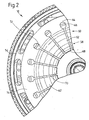
- Fig. 2
- eine Teil-Axialansicht der Kupplungsanordnung der Fig. 1 in Blickrichtung II;
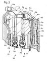
- Fig. 3
- eine der Fig. 1 entsprechende Ansicht einer alternativen Ausgestaltungsform einer Kupplungsanordnung;
- Fig. 4
- eine Axialansicht eines bei der Kupplungsanordnung der Fig. 3 eingesetzten Gehäuseteils;
- Fig. 5
- eine weitere der Fig. 1 entsprechende Ansicht einer alternativen Ausgestaltungsform einer Kupplungsanordnung;
- Fig. 6
- eine Teil-Axialansicht einer bei der Kupplungsanordnung der Fig. 5 eingesetzten Einrückkraftübertragungshebelanordnung;
- Fig. 7
- eine weitere der Fig. 1 enstprechende Ansicht einer alternativen Ausgestaltungsform einer Kupplungsanordnung;
- Fig. 8
- eine Teil-Axialansicht einer bei der Kupplungsanordnung der Fig. 7 einsetzbaren Einrückkraftübertragungshebelanordnung;
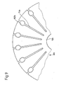
- Fig. 9
- eine der Fig. 8 entsprechende Ansicht einer alternativen Ausgestaltungsart einer Einrückkraftübertragungshebelanord-nung;
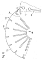
- Fig. 10
- eine der Fig. 8 entsprechende Ansicht einer alternativen Ausgestaltungsart einer Einrückkraftübertragungshebelanord-nung;
- Fig. 11
- eine der Fig. 8 entsprechende Ansicht einer alternativen Ausgestaltungsart einer Einrückkraftübertragungshebelanord-nung;
- Fig. 12
- eine der Fig. 8 entsprechende Ansicht einer alternativen Ausgestaltungsart einer Einrückkraftübertragungshebelanord-nung.
- Fig.1
- a partial longitudinal sectional view of a coupling arrangement according to the invention;
- Fig. 2
- a partial axial view of the clutch assembly of Figure 1 in the direction II.;
- Fig. 3
- a view corresponding to Figure 1 of an alternative embodiment of a clutch assembly.
- Fig. 4
- an axial view of a housing used in the clutch assembly of Figure 3;
- Fig. 5
- a further of Figure 1 corresponding view of an alternative embodiment of a clutch assembly.
- Fig. 6
- a partial axial view of an engaging force transmission lever assembly used in the clutch assembly of Figure 5;
- Fig. 7
- a further of Figure 1 Enstprechende view of an alternative embodiment of a clutch assembly.
- Fig. 8
- a partial axial view of an insertable in the clutch assembly of Figure 7 Einrückkraftübertragungshebelanordnung;
- Fig. 9
- a view similar to Figure 8 of an alternative embodiment of an engagement force transmission lever assembly;
- Fig. 10
- a view similar to Figure 8 of an alternative embodiment of an engagement force transmission lever assembly;
- Fig. 11
- a view similar to Figure 8 of an alternative embodiment of an engagement force transmission lever assembly;
- Fig. 12
- one of the Fig. 8 corresponding view of an alternative embodiment of an engagement force transmission lever arrangement.
Eine erste Ausgestaltungsform einer in Form einer Doppelkupplung aufgebauten erfindungsgemäßen Kupplungsanordnung 10 ist in den Figuren 1 und 2 dargestellt. Diese Kupplungsanordnung 10 umfasst eine allgemein mit 12 bezeichnete Gehäuseanordnung, die wiederum zwei Gehäusebauteile 14, 16 umfasst. Das als Gussteil hergestellte Gehäusebauteil 14 ist in seinem radial äußeren, sich näherungsweise axial erstreckenden Bereich an ein Mitnahmeelement 18 angebunden, das wiederum an eine Antriebswelle, eine Schwungmasse, beispielsweise auch ein Zweimassenschwungrad, angekoppelt sein kann. Mit einem ringartigen Abschnitt 20 bildet das Gehäuseteil 14 eine Zwischenplatte. Das Gehäuseteil 16 ist vorzugsweise als Blechumformteil ausgebildet und ist in seinem radial äußeren Bereich mit dem Gehäuseteil 14 durch eine Mehrzahl von Schraubbolzen 22 fest verbunden.A first embodiment of a
In dem Gehäuseteil 16 ist eine erste Anpressplatte 24 derart angeordnet, dass sie beispielsweise über Tangentialblattfedern o. dgl. mit dem Gehäuseteil 16 im Wesentlichen drehfest gekoppelt ist, in Richtung einer Drehachse jedoch verlagerbar ist. Zwischen der Anpressplatte 24 und der Zwischenplatte 20 liegt eine erste Kupplungsscheibe 26 mit ihren Reibbelägen 28. Um die erste Anpressplatte 24 in Richtung auf die Zwischenplatte 20 zu vorzuspannen und dabei die Kupplungsscheibe 26 fest einzuklemmen, ist eine erste Einrückkraftübertragungshebelanordnung 30 vorgesehen. Ein möglicher konstruktiver Aufbau dieser Einrückkraftübertragungshebelanordnung wird nachfolgend mit Bezug auf andere Ausgestaltungsformen noch detailliert beschrieben. Hier sei so viel ausgeführt, dass diese Übertragungshebelanordnung eine Mehrzahl von in Umfangsrichtung aufeinander folgenden Hebelabschnitten 32 umfasst, die sich im dargestellten Beispiel in ihrem radial äußeren Endbereich 34 am Gehäuseteil 16 beispielsweise über einen Drahtring 36 abstützen, die in einem radial mittleren, d.h. weiter innen gelegenen Bereich 38 die Anpressplatte 24 beaufschlagen und die in einem radial inneren, in Fig. 1 nicht dargestellten Bereich durch einen Einrückkrafterzeugungsmechanismus beaufschlagt werden können, so dass sie, im Wesentlichen ohne einen eigenen wesentlichen Kraftbeitrag zu liefern, bei entsprechender Einrückkrafterzeugung mit ihrem radial mittleren Bereich 38 die Anpresslatte 24 beaufschlagen und sich dabei reaktionskraftmäßig am Gehäuseteil 16 abstützen.In the
Die Anpressplatte 24, die Kupplungsscheibe 26, die Zwischenplatte 20 und die erste Einrückkraftübertragungshebelanordnung 30 bilden zusammen im Wesentlichen einen ersten Kupplungsbereich 40 der Doppelkupplungsanordnung 10. Ein zweiter Kupplungsbereich 42 umfasst im Wesentlichen eine zweite Anpressplatte 44, die im Gehäuseteil 14 drehfest, bezüglich diesem jedoch axial verlagerbar getragen ist. Zwischen dieser zweiten Anpressplatte 44 und der Zwischenplatte 20 liegt eine zweite Kupplungsscheibe 46 mit ihren Reibbelägen 48. Ein ringartig ausgebildetes Einrückkraftübertragungselement beaufschlagt die Anpressplatte 44 beispielsweise über eine Verschleißnachstellvorrichtung 52. Dieses Einrückkraftübertragungselement 50 ist durch in der Fig. 1 nicht dargestellte beispielsweise als Zuganker ausgebildete Verbindungselemente gekoppelt mit einem weiteren Einrückkraftübertragungselement 54, das, ebenso wie das Gehäuseteil 16, vorzugsweise als Blechumformteil bereitgestellt ist und eine topfartige Konfiguration aufweist. Im Topfwandungsbereich 56 ist dieses Einrückkraftübertragungselement 50 dann durch die angesprochenen Verbindungselemente mit dem Einrückkraftübertragungselement 50 gekoppelt. Mit seinem Topfbodenbereich 58 bildet dieses Einrückkraftübertragungselement 54 gleichzeitig auch eine zweite Einrückkraftübertragungshebelanordnung 60. Auch diese umfasst, wie in Fig. 2 erkennbar, eine Mehrzahl von in Umfangsrichtung aufeinander folgenden Hebelabschnitten 62, die in einem radial äußeren ringartigen Bereich 64 des Bodenbereichs 58 miteinander verbunden sind. Die einzelnen Hebelabschnitte 62 stützen sich über einen Drahtring 66 am Gehäuseteil 16 ab, und zwar an der der Abstützung der ersten Einrückkraftübertragungshebelanordnung 30 entgegengesetzten Seite. In ihrem radial inneren Bereich 68 liegen die Hebelabschnitte 62 zur Beaufschlagung durch einen Einrückkrafterzeugungsmechanismus frei, so dass bei drückender Beaufschlagung, also Beaufschlagung in der Fig. 1 nach links in diesen radial inneren Bereichen, durch die Abstützung am Drahtring 66 die einzelnen Hebelabschnitte 62 mit ihrem radial äußeren integral an das Einrückkraftübertragungselement 54 anschließenden Bereich in der Darstellung der Fig. 1 axial nach rechts, also vom Gehäuseteil 16 weg bewegt werden. Über den Wandungsbereich 56 wird damit auch das Einrückkraftübertragungselement 50 in der Fig. 1 nach rechts bewegt, was wiederum bedeutet, dass dadurch die Anpressplatte 44 in Richtung auf die Zwischenplatte 20 zu beaufschlagt wird.The
Man erkennt in Fig. 2 ferner, dass die einzelnen Hebelabschnitte 62 durch Aussparungsbereiche 70 voneinander getrennt sind, die in ihrem radial äußeren Bereich in erweiterten Abschnitten 72 enden. Es wird auf diese Art und Weise eine weitgehende kraftmäßige Entkopplung der einzelnen Hebelabschnitte 62 voneinander erreicht, so dass diese in ihrem Verbund nicht als Membranfeder o. dgl. wirksam sind, sondern bei Beaufschlagungen also keinen eigenen Kraftbeitrag bzw. Kraftwiderstand liefern.It can also be seen in FIG. 2 that the
Durch das Zusammenfassen der Einrückkraftübertragungshebelanordnung 60 mit dem Einrückkraftübertragungselement 54 wird eine Bauteileverschmelzung erlangt, die einen einfachen Aufbau der Kupplungsanordnung 10 mit sich bringt. Gleichzeitig wird durch die integrale Zusammenkopplung der einzelnen Hebelabschnitte 62 durch den einen ringartigen Verbindungsbereich 74 für diese bereitstellenden Bereich 64 des Einrückkraftübertragungselements 54 eine Fliehkrafteinwirkung auf die Hebelcharakteristik weitestgehend ausgeschaltet.By combining the engagement force
In den Figuren 3 und 4 ist eine alternative Ausgestaltungsform einer erfindungsgemäßen Kupplungsanordnung gezeigt. Komponenten, welche vorangehend beschriebenen Komponenten hinsichtlich Aufbau bzw. Funktion entsprechen, sind mit dem gleichen Bezugszeichen unter Hinzufügung eines Anhangs "a" bezeichnet. Es sei hier darauf hingewiesen, dass der grundsätzliche Aufbau der in den Figuren 3 und 4 gezeigten Doppelkupplungsanordnung 10a dem vorangehend mit Bezug auf die Figuren 1 und 2 beschriebenen Aufbau entspricht, so dass auf die diesbezüglichen Ausführungen verwiesen werden kann.FIGS. 3 and 4 show an alternative embodiment of a clutch arrangement according to the invention. Components which correspond to the above-described components in terms of design are denoted by the same reference numeral with the addition of an appendix "a". It should be noted here that the basic construction of the dual-
Im Unterschied zu der vorangehend beschriebenen Ausgestaltungsform ist bei der in Fig. 3 gezeigten Ausgestaltungsform nunmehr die Einrückkraftübertragungshebelanordnung 30a des ersten Kupplungsbereichs 40a nicht als eigenständige Baugruppe bereitgestellt, sondern bauteilemäßig mit einem anderen Bauteil, nämlich dem Gehäuseteil 16a verschmolzen. Dieses ist wiederum topfartig ausgebildet und bildet nunmehr mit seinem Bodenbereich 76a die Einrückkraftübertragungshebelanordnung 30a. Wie man in Fig. 4 erkennt, schließen hier also die einzelnen Hebelabschnitte 32a radial außen an einen ringartigen Bereich 78a des Bodenbereichs 76a an, welcher ringartige Bereich 78a nunmehr wiederum einen Verbindungsbereich 74a für die einzelnen Hebelabschnitte 32a bildet. Die Hebelabschnitte 32a beaufschlagen die Anpressplatte 24a in ihrem radial mittleren oder weiter innen gelegenen Bereich direkt oder ggf. über eine Verschleißnachstellvorrichtung und sind in ihrem radial inneren Bereich 80a zur Beaufschlagung durch einen Einrückkraftübertragungsmechanismus ausgebildet.In contrast to the embodiment described above, in the embodiment shown in FIG. 3, the engagement force
Um auch die Einrückkraftübertragungshebelanordnung 60a des zweiten Kupplungsbereichs 42 reaktionskraftmäßig an einer axial feststehenden Baugruppe abstützen zu können, ist ein im Wesentlichen topfartig ausgebildetes Abstützgehäuse 82a vorgesehen. Dieses ist mit seinem Außenwandungsbereich 84a über den entsprechenden Außenwandungsbereich 86a des Gehäuseteils 16a geschoben und dort vorzugsweise unter Presspassung gehalten. An der Außenseite dieses Abstützgehäuses 82a stützt sich nunmehr der Drahtring 66a ab, welchen die Einrückkraftübertragungshebelanordnung 60a zur Reaktionskrafterzeugung beaufschlagt. Um hier eine stabile Verbindung zu erlangen, ist es neben dem bereits angesprochenen Pressverband auch möglich, die beiden Gehäuseteile 16a und 82a zu verschweißen, zu verschrauben, zu vernieten oder in sonstiger Weise form- bzw. materialschlüssig aneinander anzubinden.In order to be able to support the engagement force
Es sei hier darauf hingewiesen, dass es selbstverständlich möglich ist, die in den Figuren 1 und 3 gezeigten Ausgestaltungsformen zu kombinieren, also beide Einrückkraftübertragungshebelanordnungen integral auszubilden jeweils mit einem anderen Bauteil, nämlich dem Einrückkraftübertragungselement 54 der Fig. 1 einerseits und dem Gehäuseteil 16a der Fig. 3 andererseits.It should be noted that it is of course possible to combine the embodiments shown in Figures 1 and 3, so integrally form both Einrückkraftübertragungshebelanordnungen each with another component, namely the engagement
Die Figuren 5 bis 12 zeigen weitere Varianten erfindungsgemäßer Doppelkupplungen. Hier sind Komponenten, welche vorangehend beschriebenen Komponenten hinsichtlich Aufbau bzw. Funktion entsprechen, mit dem gleichen Bezugszeichen unter Hinzufügung eines Anhangs "b" bezeichnet. Auch bei diesen Ausgestaltungsformen ist der grundsätzliche Aufbau der Doppelkupplungsanordnung so wie vorangehend beschrieben.FIGS. 5 to 12 show further variants of double clutches according to the invention. Here, components which correspond to components described above in terms of structure and function are denoted by the same reference numeral with the addition of an appendix "b". Even in these embodiments, the basic structure of the dual clutch assembly is as described above.
Die Einrückkraftübertragungshebelanordnung 60b des zweiten Kupplungbereichs 42b umfasst hier eine Mehrzahl von Hebelabschnitten 62b, die nunmehr in ihrem radial inneren Bereich 68b durch einen ringartigen Verbindungsbereich 74b miteinander fest gekoppelt sind. Von dort erstrecken sich die in Umfangsabstand zueinander liegenden Hebelabschnitte 62b nach radial außen. Das Einrückkraftübertragungselement 54b weist in seinem axialen Endbereich eine Mehrzahl von zungenartig ausgebildeten Kopplungsabschnitten 90b auf, die so positioniert sind, dass sie in Umfangsrichtung zwischen jeweils zwei Hebelabschnitte 62b eingreifen. Es ergibt sich dann die in Fig. 5 erkennbare Konfiguration, bei welcher die Hebelabschnitte 62b und die Koppelabschnitte 90b sich gegenseitig übergreifen. Ein als Drahtring ausgebildeter Kopplungsring 92b liegt radial außerhalb der Kopplungsabschnitte 90b, so, dass er in radialer Richtung auch noch sich mit den radial äußeren Enden der Hebelabschnitte 62b überlappt und somit an diesen axial abgestützt ist. Die Kopplungsabschnitte 90b werden nach dem im Wesentlichen den letzten Arbeitsschrit beim Zusammenfügen der Kupplungsanordnung 10b darstellenden axialen Heranführen der Einrückkraftübertragungshebelanordnung 62b und dem ebenfalls axialen Heranführen des Kopplungsrings 92b nach radial außen verrollt bzw. umgebogen, so dass auf diese Art und Weise ein fester Kopplungszusammenhalt zwischen dem Einrückkraftübertragungselement 54b und der Einrückkraftübertragungshebelanordnung 60b erlangt wird. Durch dieses Umbiegen bzw. Verrollen der Kopplungsabschnitte 90b in ihren Endbereichen kann gleichzeitig auch exakt die Lage der Hebelabschnitte 62b im Einbauzustand eingestellt werden.The engagement force
Bei der in Fig. 7 dargestellten Ausgestaltungsvariante stützten sich die Hebelabschnitte 62b der Einrückkraftübertragungshebelanordnung 60b in ihren radial äußeren Bereich über den ringartigen Bodenbereich 64b des wiederum im Wesentlichen topfartig ausgebildeten Einrückkraftübertragungselements 54b an diesem ab. Hier kann zur Abstützung der Hebelabschnitte 62b durch Materialumformung ein Abstützbereich 94b am Einrückkraftübertragungselement 54b bereitgestellt werden.In the embodiment variant shown in FIG. 7, the
Mit Bezug auf die Figuren 8 bis 12 werden nachfolgend verschiedene Ausgestaltungsformen anhand einer Einrückkraftübertragungshebelanordnung 60b beschrieben, welche selbstverständlich auch bei den vorangehend beschriebenen Ausgestaltungsformen Anwendung finden können und welche überdies selbstverständlich auch Anwendung finden können bei der dem ersten Kupplungsbereich 40b zugeordneten Einrückkraftübertragungshebelanordnung 30b.With reference to FIGS. 8 to 12, various embodiments will be described below with reference to an engagement force
In Fig. 8 ist eine Einrückkraftübertragungshebelanordnung 60b gezeigt, welche im Wesentlichen ringscheibenartig ausgebildet ist und in Umfangsrichtung aufeinander folgend wieder die Hebelabschnitte 62b aufweist. Diese sind in ihrem radial inneren Bereich 68b wieder durch den ringartigen Verbindungsbereich 74b integral miteinander verbunden, wobei hier darauf hingewiesen sei, dass, ebenso wie bei den vorangehend beschriebenen Ausgestaltungsformen, diese Übertragungshebelanordnung 60b vorzugsweise durch Ausstanzen aus einem Blechrohling generiert wird. Durch Materialaussparungen 70b, welche in ihrem radial inneren, an den Verbindungsbereich 74b anschließenden Endbereich 98b erweitert sind, sind die einzelnen Hebelabschnitte 60b voneinander getrennt. Auf diese Art und Weise werden vor allem im Bereich der Anbindung an den Verbindungsbereich 74b die Hebelabschnitte 60b mit geringer Materialstärke bereitgestellt, was deren kräftemäßige Entkopplung unterstützt. Um gleichwohl aber die Hebelabschnitte 60b zur Einrückkraftübertragung ausreichend starr zu gestalten, können zumindest einige dieser in radialer Richtung verlaufende und beispielsweise durch Einprägung oder Umformung generierte rippenartige Vertiefungen bzw. Erhöhungen 100b aufweisen.8, an engagement force
Bei der in Fig. 9 dargestellten Ausgestaltungsform einer Einrückkraftübertragungshebelanordnung 60b sind die Materialaussparungen 70b in einem radial weiter außen liegenden Bereich 102b erweitert, was insbesondere auch dazu vorteilhaft sein kann, die Einrückkraftübertragungshebelanordnung 60b durch in Fig. 5 beispielsweise erkennbare Bolzenelemente 104b am Gehäuse oder einem sonstigen Abstützelement festzulegen.In the embodiment of an engagement force
In Fig. 10 ist eine Ausgestaltungsform gezeigt, bei welcher die einzelnen Hebelabschnitte 62b der Einrückkraftübertragungshebelanordnung 60b nicht mehr im radial inneren Bereich, sondern in einem zwischen dem radial inneren Bereich 68b und dem radial äußeren Bereich 106b gelegenen Bereich durch einen ringartig umlaufenden Verbindungsbereich 74b, jeweils gebildet durch einzelne Verbindungsabschnitte zwischen den Hebelabschnitten 62b, verbunden sind. Dies kann gleichzeitig auch der Bereich sein, in welchem die Hebelabschnitte 60b beispielsweise bezüglich des Gehäuseteils 16b abgestützt sind, und welcher somit also im Wesentlichen den Schwenklagerbereich für die einzelnen Hebelabschnitte 62b bildet. Bei der in Fig. 11 dargestellten Abwandlung dieser Ausgestaltungsform sind die die einzelnen Hebelabschnitte 62b trenndenen Materialaussparungen 70b in ihren radial an den Verbindungsbereich 74b angrenzenden Endbereichen wieder erweitert ausgebildet, wodurch eine Einwirkung auf die Eigenkraftcharakteristik genommen werden kann. In Fig. 12 ist eine Ausgestaltungsform einer ringscheibenartig ausgebildeten Einrückkraftübertragungshebelanordnung 60b gezeigt, bei welcher nunmehr die einzelnen Hebelabschnitte 62b in ihrem radial äußeren Bereich 106b durch einen ringartig umlaufenden Verbindungsbereich 74b miteinander gekoppelt sind. Nahe diesem Verbindungsbereich 74b weisen die einzelnen Hebelabschnitte 62b jeweils im Wesentlichen zwischen zwei Materialaussparungen 70b, welche die Hebelabschnitte 62b trennen, sich erstreckende, langlochartige Aussparungen 110b auf. Durch diese Aussparungen 110b werden die einzelnen Hebelabschnitte 62b in ihrem Bereich der Anbindung an den Verbindungsbereich 74b aufgeteilt in einzelne Abschnittssegemente geringerer Umfangserstreckung, so dass hier eine weitere kraftmäßige Entkopplung der einzelnen Hebelabschnitte 62b voneinander erlangt werden kann.10, an embodiment is shown in which the
Es sei darauf hingewiesen, dass selbstverständlich die spezielle Formgebung, der gegenseitige Umfangsabstand, im Wesentlichen definiert durch die angesprochenen Materialaussparungen 70b, sowie die radiale Erstreckungslänge der Hebelabschnitte 62b und die radiale Lage des Verbindungsbereichs 74b bezüglich der dargestellten Ausgestaltungsformen variiert werden können.It should be noted that, of course, the specific shape, the mutual circumferential distance, substantially defined by the mentioned
Claims (16)
- Clutch arrangement, comprising at least one pressure plate (44) which can be pressed in the direction of an abutting arrangement (20), and an engaging force transmission lever arrangement (60), which can be acted upon in order to transmit an engaging force to the pressure plate (44) and is supported on a housing (-16), and which introduces an engaging force into an engaging force transmission element (54), characterized in that the engaging force transmission lever arrangement (60) is integrally formed with the engaging force transmission element (54).
- Clutch arrangement according to Claim 1, characterized in that the engaging force transmission element (54) is of canister-shaped design and that the engaging force transmission lever arrangement (60) is formed in a base area (58) of the canister-like engaging force transmission element (54).
- Clutch arrangement according to Claim 1 or 2, characterized in that the engaging force transmission lever arrangement (60) comprises a plurality of lever sections (62) circumferentially succeeding one another about an axis of rotation and extending radially inwards from an annular area (64) of the engaging force transmission element (54).
- Clutch arrangement comprising at least one pressure plate (24a) capable of being pressed in the direction of an abutting arrangement (20a), the pressure plate (24a) being arranged in a housing (16a) and being coupled thereto so that it is substantially rotationally locked and displaceable in relation to said housing in the direction of an axis of rotation, and an engaging force transmission lever arrangement (30a), which acts upon the pressure plate (24a) in order to transmit an engaging force and introduces a reaction force into the housing (16a), characterized in that the engaging force transmission lever arrangement (30a) is integrally formed with the housing (16a).
- Clutch arrangement according to Claim 4, characterized in that the housing (16a) is of canister -shaped design and that the engaging force transmission lever arrangement (30a) is formed in a base area (76a) of the canister-like housing (16a).
- Clutch arrangement according to Claim 4 or 5, characterized in that the engaging force transmission lever arrangement (30a) comprises a plurality of lever sections (32a) succeeding one another in a circumferential direction and extending radially inwards from an annular area (78a) of the housing (16a).
- Clutch arrangement according to any one of Claims 4 to 5, characterized in that a canister-like support housing (82a) is connected to the housing (16a), preferably by a press-fit seating, against which support housing (82a) a further engaging force transmission lever arrangement (60a) for a further pressure plate (44a) is supported in respect of the reaction force.
- Clutch arrangement comprising at least one pressure plate (24b, 44b) which can be pressed in the direction of an abutting arrangement (20b), and an engaging force transmission lever arrangement (30b, 60b), which can be acted upon in order to transmit an engaging force to the pressure plate (24b, 44b) and is supported on a housing (16b), and which introduces an engaging force into an engaging force transmission element (54b) or a pressure plate (24b), characterized in that the engaging force transmission lever arrangement (60b) is of annular design and comprises a plurality of lever sections (62b) succeeding one another in a circumferential direction about an axis of rotation and essentially extending radially, which are interconnected in a connecting area (74b).
- Clutch arrangement according to Claim 8, characterized in that the engaging force transmission element (54b) has coupling sections (90b) succeeding one another in a circumferential direction and engaging between each two lever sections (62b) of the engaging force transmission lever arrangement (60b), and that for transmitting force the lever sections (62b) and the coupling sections (90b) are coupled by an annular coupling element (92b).
- Clutch arrangement according to Claim 8 or 9, characterized in that the connecting area (74b) connects the lever sections (62b) in their radially inner area.
- Clutch arrangement according to Claim 8 or 9, characterized in that the connecting area (74b) connects the lever sections (62b) in their radially outer area.
- Clutch arrangement according to Claim 8 or 9, characterized in that the connecting area (74b) connects the lever sections (62b) in their radially middle area.
- Clutch arrangement according to any one of Claims 8 to 12, characterized in that the lever sections (62b) have material recesses (98b) in an area close to the connecting area (74b).
- Clutch arrangement according to any one of Claims 8 to 13, characterized in that the material recesses (70b) separating the lever sections (62b) from one another in a circumferential direction are widened in at least one radial area.
- Clutch arrangement according to any one of Claims 1 to 14, characterized in that a rib-like formation (100b) extending approximately in a radial direction is formed on at least one lever section (62b).
- Clutch arrangement according to any one of Claims 1 to 15, characterized in that the clutch arrangement comprises one pressure plate (24, 44; 24a, 44a; 24b, 44b) on either side respectively of the abutting arrangement (20; 20a; 20b), that a first engaging force transmission lever arrangement (30; 30a; 30b) is supported on a housing (16; 16a; 16b) and acts upon a first pressure plate (24; 24a; 24b) in the direction of the abutting arrangement (20; 20a; 20b) and that a second engaging force transmission lever arrangement (60; 60a; 60b) transmits an engaging force to the second pressure plate (44; 44a; 44b) by way of at least one engaging force transmission element (54; 54a; 54b).
Applications Claiming Priority (3)
| Application Number | Priority Date | Filing Date | Title |
|---|---|---|---|
| DE10227266 | 2002-06-19 | ||
| DE10227266A DE10227266A1 (en) | 2002-06-19 | 2002-06-19 | clutch assembly |
| PCT/EP2003/004897 WO2004001250A1 (en) | 2002-06-19 | 2003-05-10 | Coupling arrangement |
Publications (3)
| Publication Number | Publication Date |
|---|---|
| EP1514036A1 EP1514036A1 (en) | 2005-03-16 |
| EP1514036B1 true EP1514036B1 (en) | 2006-12-27 |
| EP1514036B2 EP1514036B2 (en) | 2018-12-26 |
Family
ID=29723254
Family Applications (1)
| Application Number | Title | Priority Date | Filing Date |
|---|---|---|---|
| EP03725185.7A Expired - Lifetime EP1514036B2 (en) | 2002-06-19 | 2003-05-10 | Coupling arrangement |
Country Status (5)
| Country | Link |
|---|---|
| EP (1) | EP1514036B2 (en) |
| AT (1) | ATE349631T1 (en) |
| AU (1) | AU2003227745A1 (en) |
| DE (2) | DE10227266A1 (en) |
| WO (1) | WO2004001250A1 (en) |
Families Citing this family (1)
| Publication number | Priority date | Publication date | Assignee | Title |
|---|---|---|---|---|
| DE102010045790C5 (en) | 2009-10-12 | 2024-10-10 | Schaeffler Technologies AG & Co. KG | clutch unit with at least one friction clutch |
Family Cites Families (4)
| Publication number | Priority date | Publication date | Assignee | Title |
|---|---|---|---|---|
| DE3017563A1 (en) * | 1980-05-08 | 1981-11-12 | Fichtel & Sachs Ag, 8720 Schweinfurt | DRAWN DIAPHRAGM CLUTCH |
| DE3241709A1 (en) * | 1982-11-11 | 1984-05-17 | LuK Lamellen und Kupplungsbau GmbH, 7580 Bühl | FRICTION COUPLING UNIT |
| US4632235A (en) * | 1985-07-26 | 1986-12-30 | Dana Corporation | Clutch with cantilevered Belleville spring |
| DE3542492A1 (en) * | 1985-11-30 | 1987-06-04 | Sachs Systemtechnik Gmbh | DIAPHRAGM SPRING FOR DRAWN DIAPHRAGM SPRING COUPLING |
-
2002
- 2002-06-19 DE DE10227266A patent/DE10227266A1/en not_active Ceased
-
2003
- 2003-05-10 AU AU2003227745A patent/AU2003227745A1/en not_active Abandoned
- 2003-05-10 AT AT03725185T patent/ATE349631T1/en not_active IP Right Cessation
- 2003-05-10 EP EP03725185.7A patent/EP1514036B2/en not_active Expired - Lifetime
- 2003-05-10 WO PCT/EP2003/004897 patent/WO2004001250A1/en not_active Ceased
- 2003-05-10 DE DE50306116T patent/DE50306116D1/en not_active Expired - Lifetime
Also Published As
| Publication number | Publication date |
|---|---|
| DE10227266A1 (en) | 2004-01-15 |
| WO2004001250A1 (en) | 2003-12-31 |
| ATE349631T1 (en) | 2007-01-15 |
| DE50306116D1 (en) | 2007-02-08 |
| AU2003227745A1 (en) | 2004-01-06 |
| EP1514036A1 (en) | 2005-03-16 |
| EP1514036B2 (en) | 2018-12-26 |
Similar Documents
| Publication | Publication Date | Title |
|---|---|---|
| EP1298339B1 (en) | Multiple clutch assembly, in particular double clutch | |
| DE4420251B4 (en) | friction clutch | |
| DE69722166T2 (en) | CLUTCH MECHANISM FOR A FRICTION CLUTCH WITH REDUCED SOLVENT EFFORT | |
| DE3418558C1 (en) | Adjustable friction slip clutch | |
| WO2015120845A1 (en) | Normally-engaged clutch device | |
| DE10024088A1 (en) | Automotive clutch separates lining from clutch plate function, simplifying construction and optimizing design function | |
| DE19880946B3 (en) | Clutch mechanism for a friction clutch | |
| DE102006014599B4 (en) | Electromagnetic coupling | |
| EP1686276B1 (en) | Twin clutch with partition wall | |
| EP0952374B1 (en) | Torsional vibration damper and its method of manufacture | |
| DE102015102141B4 (en) | Transmitter for a manual transmission for a motor vehicle, assembly with transmitter, gear shaft and gear wheel and transmission | |
| EP1512881B1 (en) | Clutch assembly | |
| DE102008038100A1 (en) | Disk clutch e.g. duplex clutch, has laminated disk set compressible by hydraulically driven operating piston, which is directly or indirectly connected with disk support in rotationally engaging manner and is driven relative to disk support | |
| EP1384909B1 (en) | Double clutch assembly | |
| DE10330633A1 (en) | Pneumatically or electromotively operated disc brake | |
| EP0771963B1 (en) | Synchronring with annular spring | |
| DE19880854B3 (en) | Clutch mechanism for a friction clutch with low release force | |
| EP1910698B1 (en) | Sleeve/roller freewheel with a solid outer ring | |
| EP1514036B2 (en) | Coupling arrangement | |
| DE19725109B4 (en) | Clutch cover assembly | |
| WO2012155877A1 (en) | Power-take-off clutch arrangement for tractors | |
| WO2013149774A1 (en) | Wheel hub rotary joint arrangement | |
| DE10227330A1 (en) | Pressure plate assembly for a friction clutch | |
| EP1394434A1 (en) | Dual clutch | |
| DE69021537T3 (en) | Torsional vibration damper, in particular for motor vehicle clutches. |
Legal Events
| Date | Code | Title | Description |
|---|---|---|---|
| PUAI | Public reference made under article 153(3) epc to a published international application that has entered the european phase |
Free format text: ORIGINAL CODE: 0009012 |
|
| 17P | Request for examination filed |
Effective date: 20040916 |
|
| AK | Designated contracting states |
Kind code of ref document: A1 Designated state(s): AT BE BG CH CY CZ DE DK EE ES FI FR GB GR HU IE IT LI LU MC NL PT RO SE SI SK TR |
|
| AX | Request for extension of the european patent |
Extension state: AL LT LV MK |
|
| DAX | Request for extension of the european patent (deleted) | ||
| GRAP | Despatch of communication of intention to grant a patent |
Free format text: ORIGINAL CODE: EPIDOSNIGR1 |
|
| GRAS | Grant fee paid |
Free format text: ORIGINAL CODE: EPIDOSNIGR3 |
|
| GRAA | (expected) grant |
Free format text: ORIGINAL CODE: 0009210 |
|
| AK | Designated contracting states |
Kind code of ref document: B1 Designated state(s): AT BE BG CH CY CZ DE DK EE ES FI FR GB GR HU IE IT LI LU MC NL PT RO SE SI SK TR |
|
| PG25 | Lapsed in a contracting state [announced via postgrant information from national office to epo] |
Ref country code: IT Free format text: LAPSE BECAUSE OF FAILURE TO SUBMIT A TRANSLATION OF THE DESCRIPTION OR TO PAY THE FEE WITHIN THE PRESCRIBED TIME-LIMIT;WARNING: LAPSES OF ITALIAN PATENTS WITH EFFECTIVE DATE BEFORE 2007 MAY HAVE OCCURRED AT ANY TIME BEFORE 2007. THE CORRECT EFFECTIVE DATE MAY BE DIFFERENT FROM THE ONE RECORDED. Effective date: 20061227 Ref country code: IE Free format text: LAPSE BECAUSE OF FAILURE TO SUBMIT A TRANSLATION OF THE DESCRIPTION OR TO PAY THE FEE WITHIN THE PRESCRIBED TIME-LIMIT Effective date: 20061227 Ref country code: RO Free format text: LAPSE BECAUSE OF FAILURE TO SUBMIT A TRANSLATION OF THE DESCRIPTION OR TO PAY THE FEE WITHIN THE PRESCRIBED TIME-LIMIT Effective date: 20061227 Ref country code: NL Free format text: LAPSE BECAUSE OF FAILURE TO SUBMIT A TRANSLATION OF THE DESCRIPTION OR TO PAY THE FEE WITHIN THE PRESCRIBED TIME-LIMIT Effective date: 20061227 Ref country code: FI Free format text: LAPSE BECAUSE OF FAILURE TO SUBMIT A TRANSLATION OF THE DESCRIPTION OR TO PAY THE FEE WITHIN THE PRESCRIBED TIME-LIMIT Effective date: 20061227 Ref country code: SK Free format text: LAPSE BECAUSE OF FAILURE TO SUBMIT A TRANSLATION OF THE DESCRIPTION OR TO PAY THE FEE WITHIN THE PRESCRIBED TIME-LIMIT Effective date: 20061227 Ref country code: DK Free format text: LAPSE BECAUSE OF FAILURE TO SUBMIT A TRANSLATION OF THE DESCRIPTION OR TO PAY THE FEE WITHIN THE PRESCRIBED TIME-LIMIT Effective date: 20061227 Ref country code: CZ Free format text: LAPSE BECAUSE OF FAILURE TO SUBMIT A TRANSLATION OF THE DESCRIPTION OR TO PAY THE FEE WITHIN THE PRESCRIBED TIME-LIMIT Effective date: 20061227 Ref country code: SI Free format text: LAPSE BECAUSE OF FAILURE TO SUBMIT A TRANSLATION OF THE DESCRIPTION OR TO PAY THE FEE WITHIN THE PRESCRIBED TIME-LIMIT Effective date: 20061227 |
|
| REG | Reference to a national code |
Ref country code: GB Ref legal event code: FG4D Free format text: NOT ENGLISH |
|
| REG | Reference to a national code |
Ref country code: IE Ref legal event code: FG4D Free format text: LANGUAGE OF EP DOCUMENT: GERMAN |
|
| REF | Corresponds to: |
Ref document number: 50306116 Country of ref document: DE Date of ref document: 20070208 Kind code of ref document: P |
|
| PG25 | Lapsed in a contracting state [announced via postgrant information from national office to epo] |
Ref country code: SE Free format text: LAPSE BECAUSE OF FAILURE TO SUBMIT A TRANSLATION OF THE DESCRIPTION OR TO PAY THE FEE WITHIN THE PRESCRIBED TIME-LIMIT Effective date: 20070327 Ref country code: BG Free format text: LAPSE BECAUSE OF FAILURE TO SUBMIT A TRANSLATION OF THE DESCRIPTION OR TO PAY THE FEE WITHIN THE PRESCRIBED TIME-LIMIT Effective date: 20070327 |
|
| PG25 | Lapsed in a contracting state [announced via postgrant information from national office to epo] |
Ref country code: ES Free format text: LAPSE BECAUSE OF FAILURE TO SUBMIT A TRANSLATION OF THE DESCRIPTION OR TO PAY THE FEE WITHIN THE PRESCRIBED TIME-LIMIT Effective date: 20070407 |
|
| PG25 | Lapsed in a contracting state [announced via postgrant information from national office to epo] |
Ref country code: PT Free format text: LAPSE BECAUSE OF FAILURE TO SUBMIT A TRANSLATION OF THE DESCRIPTION OR TO PAY THE FEE WITHIN THE PRESCRIBED TIME-LIMIT Effective date: 20070528 |
|
| NLV1 | Nl: lapsed or annulled due to failure to fulfill the requirements of art. 29p and 29m of the patents act | ||
| ET | Fr: translation filed | ||
| PLBI | Opposition filed |
Free format text: ORIGINAL CODE: 0009260 |
|
| PLAX | Notice of opposition and request to file observation + time limit sent |
Free format text: ORIGINAL CODE: EPIDOSNOBS2 |
|
| 26 | Opposition filed |
Opponent name: LUK LAMELLEN UND KUPPLUNGSBAU BETEILIGUNGS KG Effective date: 20070925 |
|
| BERE | Be: lapsed |
Owner name: ZF SACHS A.G. Effective date: 20070531 |
|
| REG | Reference to a national code |
Ref country code: CH Ref legal event code: PL |
|
| PG25 | Lapsed in a contracting state [announced via postgrant information from national office to epo] |
Ref country code: MC Free format text: LAPSE BECAUSE OF NON-PAYMENT OF DUE FEES Effective date: 20070531 |
|
| PG25 | Lapsed in a contracting state [announced via postgrant information from national office to epo] |
Ref country code: LI Free format text: LAPSE BECAUSE OF NON-PAYMENT OF DUE FEES Effective date: 20070531 Ref country code: CH Free format text: LAPSE BECAUSE OF NON-PAYMENT OF DUE FEES Effective date: 20070531 |
|
| PLAF | Information modified related to communication of a notice of opposition and request to file observations + time limit |
Free format text: ORIGINAL CODE: EPIDOSCOBS2 |
|
| PG25 | Lapsed in a contracting state [announced via postgrant information from national office to epo] |
Ref country code: BE Free format text: LAPSE BECAUSE OF NON-PAYMENT OF DUE FEES Effective date: 20070531 |
|
| PG25 | Lapsed in a contracting state [announced via postgrant information from national office to epo] |
Ref country code: GR Free format text: LAPSE BECAUSE OF FAILURE TO SUBMIT A TRANSLATION OF THE DESCRIPTION OR TO PAY THE FEE WITHIN THE PRESCRIBED TIME-LIMIT Effective date: 20070328 |
|
| PG25 | Lapsed in a contracting state [announced via postgrant information from national office to epo] |
Ref country code: AT Free format text: LAPSE BECAUSE OF NON-PAYMENT OF DUE FEES Effective date: 20070510 |
|
| PG25 | Lapsed in a contracting state [announced via postgrant information from national office to epo] |
Ref country code: EE Free format text: LAPSE BECAUSE OF FAILURE TO SUBMIT A TRANSLATION OF THE DESCRIPTION OR TO PAY THE FEE WITHIN THE PRESCRIBED TIME-LIMIT Effective date: 20061227 |
|
| PLBB | Reply of patent proprietor to notice(s) of opposition received |
Free format text: ORIGINAL CODE: EPIDOSNOBS3 |
|
| PG25 | Lapsed in a contracting state [announced via postgrant information from national office to epo] |
Ref country code: LU Free format text: LAPSE BECAUSE OF NON-PAYMENT OF DUE FEES Effective date: 20070510 Ref country code: CY Free format text: LAPSE BECAUSE OF FAILURE TO SUBMIT A TRANSLATION OF THE DESCRIPTION OR TO PAY THE FEE WITHIN THE PRESCRIBED TIME-LIMIT Effective date: 20061227 |
|
| PG25 | Lapsed in a contracting state [announced via postgrant information from national office to epo] |
Ref country code: TR Free format text: LAPSE BECAUSE OF FAILURE TO SUBMIT A TRANSLATION OF THE DESCRIPTION OR TO PAY THE FEE WITHIN THE PRESCRIBED TIME-LIMIT Effective date: 20061227 Ref country code: HU Free format text: LAPSE BECAUSE OF FAILURE TO SUBMIT A TRANSLATION OF THE DESCRIPTION OR TO PAY THE FEE WITHIN THE PRESCRIBED TIME-LIMIT Effective date: 20070628 |
|
| RDAF | Communication despatched that patent is revoked |
Free format text: ORIGINAL CODE: EPIDOSNREV1 |
|
| APBM | Appeal reference recorded |
Free format text: ORIGINAL CODE: EPIDOSNREFNO |
|
| APBP | Date of receipt of notice of appeal recorded |
Free format text: ORIGINAL CODE: EPIDOSNNOA2O |
|
| APAH | Appeal reference modified |
Free format text: ORIGINAL CODE: EPIDOSCREFNO |
|
| APBQ | Date of receipt of statement of grounds of appeal recorded |
Free format text: ORIGINAL CODE: EPIDOSNNOA3O |
|
| PLAB | Opposition data, opponent's data or that of the opponent's representative modified |
Free format text: ORIGINAL CODE: 0009299OPPO |
|
| R26 | Opposition filed (corrected) |
Opponent name: LUK VERMOEGENSVERWALTUNGSGESELLSCHAFT MBH Effective date: 20070925 |
|
| RAP2 | Party data changed (patent owner data changed or rights of a patent transferred) |
Owner name: ZF FRIEDRICHSHAFEN AG |
|
| PLAB | Opposition data, opponent's data or that of the opponent's representative modified |
Free format text: ORIGINAL CODE: 0009299OPPO |
|
| APBU | Appeal procedure closed |
Free format text: ORIGINAL CODE: EPIDOSNNOA9O |
|
| REG | Reference to a national code |
Ref country code: DE Ref legal event code: R081 Ref document number: 50306116 Country of ref document: DE Owner name: ZF FRIEDRICHSHAFEN AG, DE Free format text: FORMER OWNER: ZF SACHS AG, 97424 SCHWEINFURT, DE Effective date: 20121030 |
|
| R26 | Opposition filed (corrected) |
Opponent name: LUK VERMOEGENSVERWALTUNGSGESELLSCHAFT MBH Effective date: 20070925 |
|
| PLAB | Opposition data, opponent's data or that of the opponent's representative modified |
Free format text: ORIGINAL CODE: 0009299OPPO |
|
| R26 | Opposition filed (corrected) |
Opponent name: LUK VERMOEGENSVERWALTUNGSGESELLSCHAFT MBH Effective date: 20070925 |
|
| PLAB | Opposition data, opponent's data or that of the opponent's representative modified |
Free format text: ORIGINAL CODE: 0009299OPPO |
|
| R26 | Opposition filed (corrected) |
Opponent name: LUK VERMOEGENSVERWALTUNGSGESELLSCHAFT MBH Effective date: 20070925 |
|
| PLAB | Opposition data, opponent's data or that of the opponent's representative modified |
Free format text: ORIGINAL CODE: 0009299OPPO |
|
| R26 | Opposition filed (corrected) |
Opponent name: LUK VERMOEGENSVERWALTUNGSGESELLSCHAFT MBH Effective date: 20070925 |
|
| APAH | Appeal reference modified |
Free format text: ORIGINAL CODE: EPIDOSCREFNO |
|
| APBM | Appeal reference recorded |
Free format text: ORIGINAL CODE: EPIDOSNREFNO |
|
| APBP | Date of receipt of notice of appeal recorded |
Free format text: ORIGINAL CODE: EPIDOSNNOA2O |
|
| REG | Reference to a national code |
Ref country code: GB Ref legal event code: 732E Free format text: REGISTERED BETWEEN 20150326 AND 20150401 |
|
| APBQ | Date of receipt of statement of grounds of appeal recorded |
Free format text: ORIGINAL CODE: EPIDOSNNOA3O |
|
| REG | Reference to a national code |
Ref country code: FR Ref legal event code: PLFP Year of fee payment: 14 |
|
| REG | Reference to a national code |
Ref country code: FR Ref legal event code: PLFP Year of fee payment: 15 |
|
| REG | Reference to a national code |
Ref country code: FR Ref legal event code: PLFP Year of fee payment: 16 |
|
| APBU | Appeal procedure closed |
Free format text: ORIGINAL CODE: EPIDOSNNOA9O |
|
| PUAH | Patent maintained in amended form |
Free format text: ORIGINAL CODE: 0009272 |
|
| STAA | Information on the status of an ep patent application or granted ep patent |
Free format text: STATUS: PATENT MAINTAINED AS AMENDED |
|
| 27A | Patent maintained in amended form |
Effective date: 20181226 |
|
| AK | Designated contracting states |
Kind code of ref document: B2 Designated state(s): AT BE BG CH CY CZ DE DK EE ES FI FR GB GR HU IE IT LI LU MC NL PT RO SE SI SK TR |
|
| REG | Reference to a national code |
Ref country code: DE Ref legal event code: R102 Ref document number: 50306116 Country of ref document: DE |
|
| PGFP | Annual fee paid to national office [announced via postgrant information from national office to epo] |
Ref country code: GB Payment date: 20220323 Year of fee payment: 20 |
|
| PGFP | Annual fee paid to national office [announced via postgrant information from national office to epo] |
Ref country code: FR Payment date: 20220308 Year of fee payment: 20 |
|
| PGFP | Annual fee paid to national office [announced via postgrant information from national office to epo] |
Ref country code: DE Payment date: 20220316 Year of fee payment: 20 |
|
| REG | Reference to a national code |
Ref country code: DE Ref legal event code: R071 Ref document number: 50306116 Country of ref document: DE |
|
| REG | Reference to a national code |
Ref country code: GB Ref legal event code: PE20 Expiry date: 20230509 |
|
| P01 | Opt-out of the competence of the unified patent court (upc) registered |
Effective date: 20230528 |
|
| PG25 | Lapsed in a contracting state [announced via postgrant information from national office to epo] |
Ref country code: GB Free format text: LAPSE BECAUSE OF EXPIRATION OF PROTECTION Effective date: 20230509 |