EP1513430B1 - Modular rack - Google Patents
Modular rack Download PDFInfo
- Publication number
- EP1513430B1 EP1513430B1 EP02737252A EP02737252A EP1513430B1 EP 1513430 B1 EP1513430 B1 EP 1513430B1 EP 02737252 A EP02737252 A EP 02737252A EP 02737252 A EP02737252 A EP 02737252A EP 1513430 B1 EP1513430 B1 EP 1513430B1
- Authority
- EP
- European Patent Office
- Prior art keywords
- storage unit
- alignment
- walls
- rails
- openings
- Prior art date
- Legal status (The legal status is an assumption and is not a legal conclusion. Google has not performed a legal analysis and makes no representation as to the accuracy of the status listed.)
- Expired - Lifetime
Links
- 210000002105 tongue Anatomy 0.000 claims abstract description 54
- XLYOFNOQVPJJNP-UHFFFAOYSA-N water Substances O XLYOFNOQVPJJNP-UHFFFAOYSA-N 0.000 claims description 30
- 230000000452 restraining effect Effects 0.000 claims 1
- 238000000034 method Methods 0.000 description 7
- 239000000463 material Substances 0.000 description 4
- 239000000969 carrier Substances 0.000 description 3
- 230000000284 resting effect Effects 0.000 description 3
- 230000008901 benefit Effects 0.000 description 2
- 238000006073 displacement reaction Methods 0.000 description 2
- 239000004033 plastic Substances 0.000 description 2
- 239000000853 adhesive Substances 0.000 description 1
- 230000001070 adhesive effect Effects 0.000 description 1
- 230000002411 adverse Effects 0.000 description 1
- XAGFODPZIPBFFR-UHFFFAOYSA-N aluminium Chemical compound [Al] XAGFODPZIPBFFR-UHFFFAOYSA-N 0.000 description 1
- 229910052782 aluminium Inorganic materials 0.000 description 1
- 230000008859 change Effects 0.000 description 1
- 230000005484 gravity Effects 0.000 description 1
- 238000001746 injection moulding Methods 0.000 description 1
- 230000004048 modification Effects 0.000 description 1
- 238000012986 modification Methods 0.000 description 1
- 239000004417 polycarbonate Substances 0.000 description 1
- 229920000515 polycarbonate Polymers 0.000 description 1
- 230000035939 shock Effects 0.000 description 1
- 125000006850 spacer group Chemical group 0.000 description 1
Images


Classifications
-
- A—HUMAN NECESSITIES
- A47—FURNITURE; DOMESTIC ARTICLES OR APPLIANCES; COFFEE MILLS; SPICE MILLS; SUCTION CLEANERS IN GENERAL
- A47B—TABLES; DESKS; OFFICE FURNITURE; CABINETS; DRAWERS; GENERAL DETAILS OF FURNITURE
- A47B81/00—Cabinets or racks specially adapted for other particular purposes, e.g. for storing guns or skis
- A47B81/007—Racks for cylindrical or barrel-like objects, e.g. casks, rolls
-
- A—HUMAN NECESSITIES
- A47—FURNITURE; DOMESTIC ARTICLES OR APPLIANCES; COFFEE MILLS; SPICE MILLS; SUCTION CLEANERS IN GENERAL
- A47B—TABLES; DESKS; OFFICE FURNITURE; CABINETS; DRAWERS; GENERAL DETAILS OF FURNITURE
- A47B87/00—Sectional furniture, i.e. combinations of complete furniture units, e.g. assemblies of furniture units of the same kind such as linkable cabinets, tables, racks or shelf units
- A47B87/02—Sectional furniture, i.e. combinations of complete furniture units, e.g. assemblies of furniture units of the same kind such as linkable cabinets, tables, racks or shelf units stackable ; stackable and linkable
- A47B87/0207—Stackable racks, trays or shelf units
Definitions
- This invention relates generally to a modular rack for storing generally cylindrical storable members, such as water bottles, and more specifically to stackable storage units having two directional alignment and interlock features that can be stacked to form a stable, transportable modular rack.
- Generally cylindrical water bottles are used in water coolers. These water bottles are typically handled, transported, and stored in varying quantities. For easier handling, transport, and storage, the water bottles may be loaded in carriers designed to accommodate multiple bottles.
- aluminum and plastic modular racks are available comprising carriers designed to be vertically stackable. These modular racks are formed by stacking bottle storage units or carriers.
- the storage units have feet extending from the bottom of the unit with openings therein and interlocking projections extending from the top of the unit. The feet can support the unit on the ground or can be interlocked with projections from another unit to form a vertical stack.
- United States Patent 6, 290, 074 discloses a storage rack having the features of the pre-characterizing portion of claim 1. However, it comprises shelves interconnected by removable spacers A problem with this storage rack is that it is difficult to stack the shelves on top of one another when they are full.
- an exemplary embodiment of the present invention provides a stackable storage unit that may be vertically stacked to form a modular rack for storage and transportation of storable members, such as water bottles.
- the storage unit comprises at least one pair of rails extending in a first direction (generally parallel to the longitudinal axis of a water bottle resting on the pair of rails) and having a contoured surface for supporting a surface area of a generally cylindrical storable member.
- At least two generally vertical walls extend in the first direction on opposing ends of the storage unit.
- the walls comprise a flat top surface with a plurality of alignment openings therein.
- a plurality of alignment tongues extending from the bottom of the wall are positioned and configured to engage corresponding alignment openings in an underlying storage unit.
- a connecting structure e.g. a rib structure
- Feet extend to a level below the bottom of the alignment tongues and support the storage unit on a generally flat surface or fit inside the walls of an underlying storage unit when stacked.
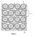
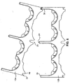
- Fig. 1 is a stack of storage units according to an exemplary embodiment of the present invention with water bottles stored therein;
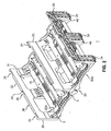
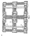
- Fig 2 is a top isometric view of a storage unit according to an exemplary embodiment of the present invention.
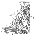
- Fig. 3 is a bottom isometric view of the storage unit shown in Fig. 2 ;
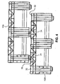
- Fig. 4 is a side view of two storage units according to an exemplary embodiment of the present invention, showing alignment and interconnect features;
- Fig. 5 is a side view of two storage units according to an exemplary embodiment of the present invention, showing a feature for preventing incorrect orientation of a vertically stacked storage unit;
- Fig. 6 is a front view of two storage units showing a primary alignment groove providing enhanced alignment and interlock functions
- Fig. 7 is top view of a frame for supporting one or more stacked storage units according to an exemplary embodiment of the present invention.
- Fig. 8 is a bottom view of the frame shown in Fig. 7 .
- Fig. 1 shows a stack of four stackable storage units 1, according to an exemplary embodiment of the present invention.
- Each storage unit 1 holds a plurality of water bottles 8, and is interlocked with an underlying storage unit or with a frame 60.
- the modular rack of the present invention enhances alignment of vertically stacked storage units, increasing the margin for initial displacement, and providing a quicker and easier two-step alignment procedure.
- the modular rack of the present invention also enhances interlock stability, reduces bottle damage and reduces stack height.
- Left, right, up, upward, above, down, downward, below, underlying, and the like shall indicate that direction when looking at Fig. 1 .
- Front and forward indicate the direction out of Fig. 1
- Lateral indicates the axis extending from the left to the right of Fig. 1 .
- Vertical indicates the axis extending from the bottom to the top of Fig. 1 .
- Longitudinal indicates the axis extending into Fig. 1 , being oriented generally parallel to the axis of generally cylindrical storable members (e.g., bottles) stored in a storage unit.
- Inward and inwardly indicates the direction toward the center of the rack.
- Stackable storage unit 1 as shown in greater detail in Figs. 2 and 3 provides optimized protection for bottles stored therein, and enhanced alignment and interlocking capabilities. Storage unit 1 is also configured to reduce damage by handling equipment, such as forklifts and to reduce damage to automated loading equipment.
- Generally cylindrical storable units, such as water bottles are stored in a plurality of apertures 5.
- Apertures 5 are bounded by two or more rails 10 having a surface contoured to support a generally cylindrical surface of a storable member (e.g., water bottle).
- a pair of axially extending rails 10, oriented essentially parallel to the axes of apertures 5, define each aperture 5.
- Two 5-gallon water bottles or three 3-gallon water bottles can be stored on each pair of rails 10.
- each pair of contoured rails provide lateral support to the water bottles, reducing damage that may be caused by lateral shifting of water bottles during transport and handling.
- the exemplary storage unit 1 illustrated in Figs. 2 and 3 comprises four apertures 5, each bounded by a pair of longitudinally extending rails 10, embodiments having a larger or smaller number of apertures are contemplated.
- rails 10 are described and illustrated with reference to generally cylindrical storable members, rails configured to support the longitudinal surfaces of a generally rectangular storable unit are also contemplated in the present invention.
- One or more primary alignment tongues 24 extend from storage unit 1 in an essentially vertical direction, preferably upwardly from storage unit 1.
- two primary alignment tongues 24 extend upwardly from a first wall 20 located in the center of storage unit 1.
- primary alignment tongues 24 and first wall 20 are oriented in a first direction, generally parallel to the axes of apertures 5.
- Primary alignment tongues 24 are preferably upwardly tapered, and may be positioned at the front and back of first wall 20.
- Storage unit 1 further comprises a primary alignment groove 25.
- Primary alignment groove 25 is positioned opposite primary alignment tongues 24.
- Primary alignment groove 25 has a relatively wide initial opening which tapers to an opening that is sized to provide a relatively tight fit over primary alignment tongues 24 from an underlying storage unit.
- storage unit 1 is positioned above an underlying storage unit such that alignment groove 25 is positioned approximately over and oriented approximately parallel to primary alignment tongues 24 from an underlying storage unit.
- alignment tongues 24 from the underlying storage unit enter the tapered portion of alignment groove 25.
- the taper in alignment groove 25 self-aligns storage unit 1 with the underlying storage unit by laterally centering alignment groove 25 on alignment tongues at the front and back of the underlying storage unit.
- primary alignment features 24 and 25 allow an overlying storage unit to be laterally displaced relative to an underlying storage unit by up to an inch.
- Storage unit 1 further comprises at least two generally vertical second walls 30 disposed on opposing lateral ends of storage unit 1.
- Second walls 30 extend in the first direction, (i.e., longitudinally).
- access openings 31 may be provided in second walls 30 to allow access to water bottles stored in storage unit 1.
- Second walls 30 comprise a flat top surface or sliding face 32 with a plurality of alignment openings 35 therein.
- a plurality of secondary alignment tongues 34 extend downwardly from the bottom of second walls 30. Secondary alignment tongues 34 are positioned and configured to engage corresponding alignment openings 35 in an underlying storage unit. As shown in Figs.
- alignment openings 35 preferably extend partially into second walls 30 toward apertures 5, and are each bounded by an outside face 39 (i.e., facing away from first wall 20). As shown in Figs. 2 and 3 , alignment openings 35 may be open to the outside surface 38 of second walls 30, exposing outside faces 39 (shown in Fig. 3 ).
- Secondary alignment tongues 34 may be tapered to provide ease of engagement with alignment openings 35, and preferably terminate in a flat surface 36. In an engaged position, secondary alignment tongues 34 extend into alignment openings 35 and abut outside faces 39 of second walls 30, locking vertically stacked storage units together such that storage unit 1 is restrained from moving laterally or horizontally with respect to an underlying storage unit.
- Feet 46 extend downwardly from the bottom of storage unit 1 and support storage unit 1 when it is resting on a generally flat surface, such as a floor or the ground. Feet 46 extend below alignment tongues 34, protecting alignment tongues 34 from wear and damage from contact with the ground. Feet 46 may be located adjacent alignment tongues 34 with an opening between corresponding feet 46 and alignment tongues 34 to receive second wall 30 at the locations of alignment openings 35. Primary alignment tongues 24 and primary alignment groove 25 are disposed to engage before alignment tongues 34 and alignment openings 35 when vertically stacked storage units are brought together. In this way, alignment tongues 34 are aligned to alignment openings 35 in a lateral direction by primary alignment features 24 and 25.
- Alignment of vertically stacked storage units may be performed in a two-step procedure. Accordingly, primary alignment tongues 24 of an underlying storage unit may be engaged in primary alignment groove 25 of an overlying storage unit, to provide lateral alignment in a first step. Primary alignment groove 25 is tapered to self-center over primary alignment tongues 24. In the first step, primary alignment groove 25 may be displaced by almost half of its initial width (about one inch) from alignment with primary alignment tongues 24, and alignment tongues 34 may be displaced from alignment openings 35 in the longitudinal direction by a margin of up to about ten inches. When alignment tongues 34 are longitudinally displaced relative to alignment openings 35, flat surface 36 of alignment tongues 34 rest on sliding surface 32 of second walls 30.
- the overlying storage unit is slid longitudinally forward or backward until the alignment tongues 34 of the overlying storage unit align with the alignment openings 35 of the underlying storage unit.
- alignment tongues 34 are aligned with alignment openings 35, gravity causes the alignment tongues to engage in the alignment openings interlocking the vertically stacked storage units. Because the flat surface 36 on the bottom of alignment tongues 34 slides on the flat sliding surface 32 on the top of second walls 30, there is very little friction, and sliding can be accomplished with a small longitudinal force. Alignment tongues 34 are held on sliding surface 32 by engagement of self-centering primary alignment groove 25 over primary alignment tongues 24.
- lateral alignment can be accomplished without simultaneously controlling longitudinal alignment in the first step, and longitudinal alignment can be accomplished without simultaneously controlling lateral alignment. Because each alignment axis can be addressed separately, the two-step alignment procedure (slide and lock) is easy to perform and requires minimal time and provides greater margins for initial displacement during alignment.
- Rib structure 50 is disposed under rails 10 such that rib structure 50 does not contact a storable member supported by rails 10.
- Rib structure 50 comprises an interconnected network of generally vertical ribs providing vertical support to rails 10 as well as maintaining the position and alignment of rails 10, first wall 20, and second walls 30 relative to each other. As shown in Figs. 2 and 3 , rib structure 50 may have openings between the vertical ribs, reducing material, weight, and cost of storage unit 10.
- Rib structure 50 may be contoured to define a top portion of apertures 5, reducing the clearance between water bottles stored on an underlying storage unit and an overlying storage unit. Accordingly, the maximum bounce of a water bottle due to vibration in transport and handling is reduced, as well as, damage resulting from such bounce.
- Storage unit 10 may comprise a variety of materials having the appropriate strength for supporting a plurality of storable units.
- storage unit 10 comprises polycarbonate, and is formed by an injection molding process.
- an overlying storage unit 10A is aligned in the lateral direction and displaced in the longitudinal direction relative to an underlying storage unit 10B.
- flat surfaces 36 of alignment tongues 34 rest on sliding face 32 of second wall 30.
- Storage units 10A and 10B are between the first and second steps of the two-step alignment procedure described herein.
- a forklift operator can land overlying storage unit 10A within about one inch of alignment with underlying storage unit 10B in the lateral direction and within about ten inches in the longitudinal direction.
- the self-centering primary alignment groove (not shown) will self-center on primary alignment tongues (not shown) bringing alignment tongues 34 of overlying storage unit 10A to rest on sliding surface 32 of underlying storage unit 10B.
- the forklift operator can then slide overlying storage unit 10A on sliding surface 32 of underlying storage unit 10B until alignment tongues 34 engage or interlock with alignment opening 35 of underlying storage unit 10B.
- alignment tongues 34 may be variably spaced or sized to prevent interlocking of vertically stacked storage units that are incorrectly oriented. Incorrect orientation can cause damage to automatic handling equipment by collision with non-symmetrical features of storage units 10.
- alignment tongues 34 have different spacing so that they can not be simultaneously engaged when they are incorrectly oriented, as shown.
- Second walls 30 of underlying storage unit 10B are trapped between alignment tongues 34 and feet 46 of overlying storage unit 10A.
- Primary alignment tongues 24 of underlying storage unit 10B are trapped in primary alignment groove 25 of overlying storage unit 10A. Because alignment tongues 34, feet 46, and primary alignment groove 25 do not support overlying storage unit 10A when stacked, they do not affect the stack height of vertically stacked storage units. Accordingly, the length of engagement of these structures can be increased without adversely affecting the stack height of a stack of storage units. Increased engagement length provides greater interlock stability.
- a storage rack can be bounced up to 2.75 inches and return to a fully interlocked position, providing interlock stability during transportation and handling of the storage units and modular racks comprising vertically stacked storage units. Also, because second wall 30 of underlying storage unit 10B is received in an opening between feet 46 and alignment tongues 34 of overlying storage unit 10A, pivoting by overlying storage unit 10A during transport or handling, as shown in Fig. 6 does not disturb the interlocking of storage units 10A and 10B. Second wall 30 of underlying storage unit 10B remains in the opening between feet 46 and alignment tongues 34 of overlying storage unit 10A.
- stack height can remain essentially constant over the life of a storage unit.
- feet 46 do not affect stack height. Accordingly, dimensional changes of feet 46 due to wear will not change the stack height of vertically stacked storage units. This allows storage units to be dimensioned for a closer fit at the top of vertically stored water bottles, limiting the height to which water bottles can bounce during transport and handling, and thereby reducing damage to the water bottles.
- a constant stack height also makes the use of automated loading equipment easier, because the automated equipment does not have to compensate for stack height variations.
- stack height of a modular rack can be maintained at a desirable (minimum) height.
- stack height can be maintained at 105.5 inches for a stack of eight storage units. This stack height allows a stack of eight storage units to be easily loaded in a standard 110 inch truck. Reduced stack height also facilitates easier handling of vertically stacked storage units.
- the modular rack of the present invention may further comprise a frame 60, as shown in Fig. 1 and illustrated in greater detail in Figs. 7 and 8 .
- a frame 60 as shown in Fig. 1 and illustrated in greater detail in Figs. 7 and 8 .
- simulated primary alignment tongues 124 and simulated second walls 130 are provided for engagement with primary alignment groove 25 and alignment tongue 34 and feet 46 of a storage unit 10 (as shown in Figs. 2 and 3 ).
- Support pads 170 are disposed to support rib structure 50 of storage unit 10.
- Snap fingers 180 engage storage unit 10 when it is lowered onto frame 60.
- the bottom of frame 60 has continuous smooth ribs 190, allowing frame 60 and storage units 10 stacked thereon to be transported on a conveyor roller.
- rib structure 50 is recessed at the front of storage unit 1. Ribs or other structures which are generally at the level of storable members as they are loaded on a storage rack and unloaded from the storage rack can come into contact with the storable members as they slide into and out of storage apertures. The recessed rib structure reduces damage to storable members and labels on the storable members during loading and unloading of the storable members.
- Longitudinal rails 10 may be continuous to maintain longitudinal alignment of storable members during loading and unloading. This longitudinal alignment prevents storable members from turning or cocking in the rack during loading and unloading. This feature provides improved loading and unloading and reduced damage to storable members compared to racks with generally transverse supports that allow storable members to turn and jam during loading and unloading.
- Friction plugs 200 may be installed on rails 10, as shown in Fig. 2 .
- Friction plugs may, for example, comprise rubber, plastic, or other material, preferably providing a high coefficient of friction. Friction plugs may be installed on rails 10 with adhesive, snapped into holes formed in rails 10, or attached using other techniques appropriate to the materials used for rails 10 and friction plugs 200.
- storage unit 10 may comprise forklift pockets 300, as shown in Fig. 2 .
- Forklift pockets 300 provide a specific location to drive the fork of a forklift, and provide additional clearance from water bottles stored in an underlying storage unit. Because forklift pockets 300 provide a specific location for forklift forks, forklift pockets 300 can be easily reinforced.
- Forklift pocket 300 may be provided with wide lead-in radii to direct the forks into the opening.
- forklift pockets may have mounted thereon forklift friction plugs (not shown) similar to the friction plugs 200 (in Fig. 2 ).
Landscapes
- Stackable Containers (AREA)
- Transmission Devices (AREA)
- Packaging Of Annular Or Rod-Shaped Articles, Wearing Apparel, Cassettes, Or The Like (AREA)
- Reciprocating, Oscillating Or Vibrating Motors (AREA)
- Crystals, And After-Treatments Of Crystals (AREA)
- Earth Drilling (AREA)
Abstract
Description
- This invention relates generally to a modular rack for storing generally cylindrical storable members, such as water bottles, and more specifically to stackable storage units having two directional alignment and interlock features that can be stacked to form a stable, transportable modular rack.
- Generally cylindrical water bottles are used in water coolers. These water bottles are typically handled, transported, and stored in varying quantities. For easier handling, transport, and storage, the water bottles may be loaded in carriers designed to accommodate multiple bottles. To accommodate the varying quantities of bottles, aluminum and plastic modular racks are available comprising carriers designed to be vertically stackable. These modular racks are formed by stacking bottle storage units or carriers. The storage units have feet extending from the bottom of the unit with openings therein and interlocking projections extending from the top of the unit. The feet can support the unit on the ground or can be interlocked with projections from another unit to form a vertical stack.
- Existing modular racks, however, are difficult to align, since each foot must be aligned in space with a corresponding projection so that the feet of the top unit can be lowered onto the projections of the bottom unit. Alignment becomes more difficult when the units contain full water bottles requiring the use of equipment, such as a forklift to handle the unit. A further problem with existing modular racks is that the interlock feature can be disengaged by shock or vibration during handling and transport, damaging water bottles and the rack. Water bottles can also be damaged by contact with relatively sharp exposed ribs in existing modular racks. A still further problem with existing modular racks is that they are easily damaged by handling equipment, such as forklifts. Yet another problem with existing modular racks is that they can cause damage to automatic loading equipment if they are not correctly oriented when stacked, because they are not symmetrical front to back.
- United States Patent
6, 290, 074 discloses a storage rack having the features of the pre-characterizing portion ofclaim 1. However, it comprises shelves interconnected by removable spacers A problem with this storage rack is that it is difficult to stack the shelves on top of one another when they are full. - To overcome the shortcomings of existing modular racks, a need exists for a vertically stackable modular rack that provides ease of alignment, secure interlocking, optimum bottle protection, and reduced susceptibility to damage by handling equipment.
- To meet these and other needs, and in view of its purposes, an exemplary embodiment of the present invention provides a stackable storage unit that may be vertically stacked to form a modular rack for storage and transportation of storable members, such as water bottles. The storage unit comprises at least one pair of rails extending in a first direction (generally parallel to the longitudinal axis of a water bottle resting on the pair of rails) and having a contoured surface for supporting a surface area of a generally cylindrical storable member. At least two generally vertical walls extend in the first direction on opposing ends of the storage unit. The walls comprise a flat top surface with a plurality of alignment openings therein. A plurality of alignment tongues extending from the bottom of the wall are positioned and configured to engage corresponding alignment openings in an underlying storage unit. A connecting structure (e.g. a rib structure) underlies the rails and connects the walls to the rails. Feet extend to a level below the bottom of the alignment tongues and support the storage unit on a generally flat surface or fit inside the walls of an underlying storage unit when stacked.
- It is to be understood that both the foregoing general description and the following detailed description are exemplary, but are not restrictive, of the invention.
- The invention is best understood from the following detailed description when read in connection with the accompanying drawing. It is emphasized that, according to common practice, the various features of the drawing are not to scale. On the contrary, the dimensions of the various features are arbitrarily expanded or reduced for clarity. Included in the drawing are the following figures:
-
Fig. 1 is a stack of storage units according to an exemplary embodiment of the present invention with water bottles stored therein; -
Fig 2 . is a top isometric view of a storage unit according to an exemplary embodiment of the present invention; -
Fig. 3 is a bottom isometric view of the storage unit shown inFig. 2 ; -
Fig. 4 is a side view of two storage units according to an exemplary embodiment of the present invention, showing alignment and interconnect features; -
Fig. 5 is a side view of two storage units according to an exemplary embodiment of the present invention, showing a feature for preventing incorrect orientation of a vertically stacked storage unit; -
Fig. 6 is a front view of two storage units showing a primary alignment groove providing enhanced alignment and interlock functions; -
Fig. 7 is top view of a frame for supporting one or more stacked storage units according to an exemplary embodiment of the present invention; and -
Fig. 8 is a bottom view of the frame shown inFig. 7 . - Referring now to the drawing, in which like reference numbers refer to like elements throughout,
Fig. 1 shows a stack of fourstackable storage units 1, according to an exemplary embodiment of the present invention. Eachstorage unit 1 holds a plurality ofwater bottles 8, and is interlocked with an underlying storage unit or with aframe 60. The modular rack of the present invention enhances alignment of vertically stacked storage units, increasing the margin for initial displacement, and providing a quicker and easier two-step alignment procedure. The modular rack of the present invention also enhances interlock stability, reduces bottle damage and reduces stack height. - When used herein, the following words and phrases have the meaning provided. Left, right, up, upward, above, down, downward, below, underlying, and the like shall indicate that direction when looking at
Fig. 1 . Front and forward indicate the direction out ofFig. 1 , and back and backward indicate the direction intoFig. 1 . Lateral indicates the axis extending from the left to the right ofFig. 1 . Vertical indicates the axis extending from the bottom to the top ofFig. 1 . Longitudinal indicates the axis extending intoFig. 1 , being oriented generally parallel to the axis of generally cylindrical storable members (e.g., bottles) stored in a storage unit. Inward and inwardly indicates the direction toward the center of the rack. -
Stackable storage unit 1 as shown in greater detail inFigs. 2 and3 provides optimized protection for bottles stored therein, and enhanced alignment and interlocking capabilities.Storage unit 1 is also configured to reduce damage by handling equipment, such as forklifts and to reduce damage to automated loading equipment. Generally cylindrical storable units, such as water bottles are stored in a plurality ofapertures 5.Apertures 5 are bounded by two ormore rails 10 having a surface contoured to support a generally cylindrical surface of a storable member (e.g., water bottle). Preferably, a pair of axially extendingrails 10, oriented essentially parallel to the axes ofapertures 5, define eachaperture 5. Two 5-gallon water bottles or three 3-gallon water bottles can be stored on each pair ofrails 10. Because therails 10 are contoured, they contact a greater surface area of the water bottles resting on them, reducing any stress in the water bottles, as compared to flat or sharp ribs used in existing modular racks. Also, each pair of contoured rails provide lateral support to the water bottles, reducing damage that may be caused by lateral shifting of water bottles during transport and handling. While theexemplary storage unit 1 illustrated inFigs. 2 and3 comprises fourapertures 5, each bounded by a pair of longitudinally extendingrails 10, embodiments having a larger or smaller number of apertures are contemplated. Althoughrails 10 are described and illustrated with reference to generally cylindrical storable members, rails configured to support the longitudinal surfaces of a generally rectangular storable unit are also contemplated in the present invention. - To enhance alignment of
storage unit 1 on an underlying storage unit, alignment features are provided for a two-step, two-directional alignment. One or moreprimary alignment tongues 24 extend fromstorage unit 1 in an essentially vertical direction, preferably upwardly fromstorage unit 1. In an exemplary embodiment of the present invention, twoprimary alignment tongues 24 extend upwardly from afirst wall 20 located in the center ofstorage unit 1. In the exemplary embodiment illustrated inFigs. 2 and3 ,primary alignment tongues 24 andfirst wall 20 are oriented in a first direction, generally parallel to the axes ofapertures 5.Primary alignment tongues 24 are preferably upwardly tapered, and may be positioned at the front and back offirst wall 20. -
Storage unit 1 further comprises aprimary alignment groove 25.Primary alignment groove 25 is positioned oppositeprimary alignment tongues 24. For example, in the embodiment ofstorage unit 1 illustrated inFigs. 2 and3 , whereprimary alignment tongues 24 extend upwardly fromfirst wall 20,primary alignment groove 25 is positioned in the bottom ofstorage unit 1, positioned directly underfirst wall 20.Primary alignment groove 25 has a relatively wide initial opening which tapers to an opening that is sized to provide a relatively tight fit overprimary alignment tongues 24 from an underlying storage unit. - In use,
storage unit 1 is positioned above an underlying storage unit such thatalignment groove 25 is positioned approximately over and oriented approximately parallel toprimary alignment tongues 24 from an underlying storage unit. Asstorage unit 1 is lowered onto an underlying storage unit,alignment tongues 24 from the underlying storage unit enter the tapered portion ofalignment groove 25. The taper inalignment groove 25 self-alignsstorage unit 1 with the underlying storage unit by laterally centeringalignment groove 25 on alignment tongues at the front and back of the underlying storage unit. In the exemplary embodiment illustrated inFigs. 2 and3 , primary alignment features 24 and 25 allow an overlying storage unit to be laterally displaced relative to an underlying storage unit by up to an inch. -
Storage unit 1 further comprises at least two generally verticalsecond walls 30 disposed on opposing lateral ends ofstorage unit 1.Second walls 30 extend in the first direction, (i.e., longitudinally). As shown inFigs. 2 and3 ,access openings 31 may be provided insecond walls 30 to allow access to water bottles stored instorage unit 1.Second walls 30 comprise a flat top surface or slidingface 32 with a plurality ofalignment openings 35 therein. A plurality ofsecondary alignment tongues 34 extend downwardly from the bottom ofsecond walls 30.Secondary alignment tongues 34 are positioned and configured to engagecorresponding alignment openings 35 in an underlying storage unit. As shown inFigs. 2 and3 ,alignment openings 35 preferably extend partially intosecond walls 30 towardapertures 5, and are each bounded by an outside face 39 (i.e., facing away from first wall 20). As shown inFigs. 2 and3 ,alignment openings 35 may be open to theoutside surface 38 ofsecond walls 30, exposing outside faces 39 (shown inFig. 3 ). -
Secondary alignment tongues 34 may be tapered to provide ease of engagement withalignment openings 35, and preferably terminate in aflat surface 36. In an engaged position,secondary alignment tongues 34 extend intoalignment openings 35 and abut outside faces 39 ofsecond walls 30, locking vertically stacked storage units together such thatstorage unit 1 is restrained from moving laterally or horizontally with respect to an underlying storage unit. -
Feet 46 extend downwardly from the bottom ofstorage unit 1 andsupport storage unit 1 when it is resting on a generally flat surface, such as a floor or the ground.Feet 46 extend belowalignment tongues 34, protectingalignment tongues 34 from wear and damage from contact with the ground.Feet 46 may be locatedadjacent alignment tongues 34 with an opening betweencorresponding feet 46 andalignment tongues 34 to receivesecond wall 30 at the locations ofalignment openings 35.Primary alignment tongues 24 andprimary alignment groove 25 are disposed to engage beforealignment tongues 34 andalignment openings 35 when vertically stacked storage units are brought together. In this way,alignment tongues 34 are aligned toalignment openings 35 in a lateral direction by primary alignment features 24 and 25. - Alignment of vertically stacked storage units may be performed in a two-step procedure. Accordingly,
primary alignment tongues 24 of an underlying storage unit may be engaged inprimary alignment groove 25 of an overlying storage unit, to provide lateral alignment in a first step.Primary alignment groove 25 is tapered to self-center overprimary alignment tongues 24. In the first step,primary alignment groove 25 may be displaced by almost half of its initial width (about one inch) from alignment withprimary alignment tongues 24, andalignment tongues 34 may be displaced fromalignment openings 35 in the longitudinal direction by a margin of up to about ten inches. Whenalignment tongues 34 are longitudinally displaced relative toalignment openings 35,flat surface 36 ofalignment tongues 34 rest on slidingsurface 32 ofsecond walls 30. - In a second step of the two-step procedure, the overlying storage unit is slid longitudinally forward or backward until the
alignment tongues 34 of the overlying storage unit align with thealignment openings 35 of the underlying storage unit. Whenalignment tongues 34 are aligned withalignment openings 35, gravity causes the alignment tongues to engage in the alignment openings interlocking the vertically stacked storage units. Because theflat surface 36 on the bottom ofalignment tongues 34 slides on the flat slidingsurface 32 on the top ofsecond walls 30, there is very little friction, and sliding can be accomplished with a small longitudinal force.Alignment tongues 34 are held on slidingsurface 32 by engagement of self-centeringprimary alignment groove 25 overprimary alignment tongues 24. - In the two-step alignment procedure, lateral alignment can be accomplished without simultaneously controlling longitudinal alignment in the first step, and longitudinal alignment can be accomplished without simultaneously controlling lateral alignment. Because each alignment axis can be addressed separately, the two-step alignment procedure (slide and lock) is easy to perform and requires minimal time and provides greater margins for initial displacement during alignment.
- Each pair of rails is connected together and interconnected to the first and second walls by a
rib structure 50.Rib structure 50 is disposed underrails 10 such thatrib structure 50 does not contact a storable member supported byrails 10.Rib structure 50 comprises an interconnected network of generally vertical ribs providing vertical support torails 10 as well as maintaining the position and alignment ofrails 10,first wall 20, andsecond walls 30 relative to each other. As shown inFigs. 2 and3 ,rib structure 50 may have openings between the vertical ribs, reducing material, weight, and cost ofstorage unit 10. -
Rib structure 50 may be contoured to define a top portion ofapertures 5, reducing the clearance between water bottles stored on an underlying storage unit and an overlying storage unit. Accordingly, the maximum bounce of a water bottle due to vibration in transport and handling is reduced, as well as, damage resulting from such bounce. -
Storage unit 10 may comprise a variety of materials having the appropriate strength for supporting a plurality of storable units. In an exemplary embodiment of the invention,storage unit 10 comprises polycarbonate, and is formed by an injection molding process. - Referring now to
Fig. 4 , an overlyingstorage unit 10A is aligned in the lateral direction and displaced in the longitudinal direction relative to anunderlying storage unit 10B. As shown inFig. 4 ,flat surfaces 36 ofalignment tongues 34 rest on slidingface 32 ofsecond wall 30.Storage units overlying storage unit 10A within about one inch of alignment withunderlying storage unit 10B in the lateral direction and within about ten inches in the longitudinal direction. The self-centering primary alignment groove (not shown) will self-center on primary alignment tongues (not shown) bringingalignment tongues 34 ofoverlying storage unit 10A to rest on slidingsurface 32 ofunderlying storage unit 10B. The forklift operator can then slide overlyingstorage unit 10A on slidingsurface 32 ofunderlying storage unit 10B untilalignment tongues 34 engage or interlock with alignment opening 35 ofunderlying storage unit 10B. - Referring now to
Fig. 5 ,alignment tongues 34 may be variably spaced or sized to prevent interlocking of vertically stacked storage units that are incorrectly oriented. Incorrect orientation can cause damage to automatic handling equipment by collision with non-symmetrical features ofstorage units 10. In the exemplary embodiment illustrated inFig. 5 ,alignment tongues 34 have different spacing so that they can not be simultaneously engaged when they are incorrectly oriented, as shown. - Referring now to
Fig. 6 , the interlock features of an exemplary embodiment of the invention provide interlock stability.Second walls 30 ofunderlying storage unit 10B are trapped betweenalignment tongues 34 andfeet 46 ofoverlying storage unit 10A.Primary alignment tongues 24 ofunderlying storage unit 10B are trapped inprimary alignment groove 25 ofoverlying storage unit 10A. Becausealignment tongues 34,feet 46, andprimary alignment groove 25 do not supportoverlying storage unit 10A when stacked, they do not affect the stack height of vertically stacked storage units. Accordingly, the length of engagement of these structures can be increased without adversely affecting the stack height of a stack of storage units. Increased engagement length provides greater interlock stability. In an exemplary embodiment of the present invention, a storage rack can be bounced up to 2.75 inches and return to a fully interlocked position, providing interlock stability during transportation and handling of the storage units and modular racks comprising vertically stacked storage units. Also, becausesecond wall 30 ofunderlying storage unit 10B is received in an opening betweenfeet 46 andalignment tongues 34 ofoverlying storage unit 10A, pivoting by overlyingstorage unit 10A during transport or handling, as shown inFig. 6 does not disturb the interlocking ofstorage units Second wall 30 ofunderlying storage unit 10B remains in the opening betweenfeet 46 andalignment tongues 34 ofoverlying storage unit 10A. - Another advantage of the present invention is that stack height can remain essentially constant over the life of a storage unit. In an exemplary embodiment of the invention, as described above,
feet 46 do not affect stack height. Accordingly, dimensional changes offeet 46 due to wear will not change the stack height of vertically stacked storage units. This allows storage units to be dimensioned for a closer fit at the top of vertically stored water bottles, limiting the height to which water bottles can bounce during transport and handling, and thereby reducing damage to the water bottles. A constant stack height also makes the use of automated loading equipment easier, because the automated equipment does not have to compensate for stack height variations. - Yet another advantage of the present invention is that the overall stack height of a modular rack can be maintained at a desirable (minimum) height. In an exemplary embodiment of the invention, stack height can be maintained at 105.5 inches for a stack of eight storage units. This stack height allows a stack of eight storage units to be easily loaded in a standard 110 inch truck. Reduced stack height also facilitates easier handling of vertically stacked storage units.
- The modular rack of the present invention may further comprise a
frame 60, as shown inFig. 1 and illustrated in greater detail inFigs. 7 and8 . In an exemplary embodiment as shown inFigs. 7 and8 , simulatedprimary alignment tongues 124 and simulatedsecond walls 130 are provided for engagement withprimary alignment groove 25 andalignment tongue 34 andfeet 46 of a storage unit 10 (as shown inFigs. 2 and3 ).Support pads 170 are disposed to supportrib structure 50 ofstorage unit 10.Snap fingers 180 engagestorage unit 10 when it is lowered ontoframe 60. The bottom offrame 60 has continuoussmooth ribs 190, allowingframe 60 andstorage units 10 stacked thereon to be transported on a conveyor roller. - Referring again to
Fig. 3 ,rib structure 50 is recessed at the front ofstorage unit 1. Ribs or other structures which are generally at the level of storable members as they are loaded on a storage rack and unloaded from the storage rack can come into contact with the storable members as they slide into and out of storage apertures. The recessed rib structure reduces damage to storable members and labels on the storable members during loading and unloading of the storable members. -
Longitudinal rails 10 may be continuous to maintain longitudinal alignment of storable members during loading and unloading. This longitudinal alignment prevents storable members from turning or cocking in the rack during loading and unloading. This feature provides improved loading and unloading and reduced damage to storable members compared to racks with generally transverse supports that allow storable members to turn and jam during loading and unloading. - To prevent water bottles from sliding longitudinally on
rails 10, friction plugs 200 may be installed onrails 10, as shown inFig. 2 . Friction plugs may, for example, comprise rubber, plastic, or other material, preferably providing a high coefficient of friction. Friction plugs may be installed onrails 10 with adhesive, snapped into holes formed inrails 10, or attached using other techniques appropriate to the materials used forrails 10 and friction plugs 200. - To reduce damage to water bottles and the modular rack by handling equipment such as forklifts,
storage unit 10 may comprise forklift pockets 300, as shown inFig. 2 . Forklift pockets 300 provide a specific location to drive the fork of a forklift, and provide additional clearance from water bottles stored in an underlying storage unit. Because forklift pockets 300 provide a specific location for forklift forks, forklift pockets 300 can be easily reinforced.Forklift pocket 300 may be provided with wide lead-in radii to direct the forks into the opening. To prevent the rack from sliding off the blades of a forklift, forklift pockets may have mounted thereon forklift friction plugs (not shown) similar to the friction plugs 200 (inFig. 2 ). - Although illustrated and described above with reference to certain specific embodiments, the present invention is nevertheless not intended to be limited to the details shown. Rather, various modifications may be made in the details within the scope and range of equivalents of the claims and without departing from the invention.
Claims (10)
- A stackable storage unit, comprising:at least one pair of rails (10) extending in a first direction and having a contoured surface for supporting a surface area of a storable member;at least two generally vertical walls (30) extending in the first direction disposed on opposing ends of the storage unit, the walls (30) comprising a flat top surface (32) with a plurality of alignment openings (35) therein; anda rib structure (50) underlying the rails (10) and connecting the walls (30) to the rails (10); characterized bya plurality of alignment tongues (34) extending from the bottom of the wall, the alignment tongues positioned and configured to engage corresponding alignment openings (35) in an underlying storage unit; andfeet (46) sized and configured to extend below the bottom of the alignment tongues (34) and to support the storage unit on a generally flat surface and positioned to fit inside the walls (30) of an underlying storage unit.
- The storage unit of claim 1 wherein the feet (46) and the alignment tongues (34) form interlock grooves that receive the walls of an underlying storage unit, restraining the walls (30) in a second direction essentially perpendicular to the first direction.
- The storage unit of claims 1 or 2 wherein the at least two generally vertical walls (30) have openings (31) therein to allow access to the storable member.
- The storage unit of any claims 1 to 3 wherein the rib structure (50) has openings therein to allow access to the storable member.
- The storage unit of any of claims 1 to 4 wherein the rib structure (50) is recessed at the front of the storage unit.
- The storage unit of any claims 1 to 5 wherein the storage unit defines an aperture (5) configured and sized to hold two, five-gallon water bottles.
- The storage unit of any of claims 1 to 6 wherein the rib structure (50) comprises reinforced, tapered fork lift openings (300) to prevent damage from handling the storage unit with a forklift.
- The storage unit of claim 7 further comprising forklift friction plugs mounted on the forklift openings (300) to prevent storable units from sliding off the forklift.
- The storage unit any of claims 1 to 7 further comprising friction plugs (200) mounted on the rails to prevent storable units from sliding on the rails.
- The storage unit of any of claims 1-9 further comprising a frame (60) mounted under the storage unit and configured for use on a roller conveyor.
Applications Claiming Priority (1)
| Application Number | Priority Date | Filing Date | Title |
|---|---|---|---|
| PCT/US2002/016930 WO2003101259A1 (en) | 2002-05-31 | 2002-05-31 | Modular rack |
Publications (3)
| Publication Number | Publication Date |
|---|---|
| EP1513430A1 EP1513430A1 (en) | 2005-03-16 |
| EP1513430A4 EP1513430A4 (en) | 2007-10-31 |
| EP1513430B1 true EP1513430B1 (en) | 2011-07-06 |
Family
ID=34102319
Family Applications (1)
| Application Number | Title | Priority Date | Filing Date |
|---|---|---|---|
| EP02737252A Expired - Lifetime EP1513430B1 (en) | 2002-05-31 | 2002-05-31 | Modular rack |
Country Status (10)
| Country | Link |
|---|---|
| US (1) | US6811042B2 (en) |
| EP (1) | EP1513430B1 (en) |
| AT (1) | ATE515215T1 (en) |
| AU (1) | AU2002310191A1 (en) |
| CA (1) | CA2486257C (en) |
| DK (1) | DK1513430T3 (en) |
| ES (1) | ES2369075T3 (en) |
| MX (1) | MXPA04011771A (en) |
| PT (1) | PT1513430E (en) |
| WO (1) | WO2003101259A1 (en) |
Families Citing this family (49)
| Publication number | Priority date | Publication date | Assignee | Title |
|---|---|---|---|---|
| US6851563B1 (en) * | 2002-03-08 | 2005-02-08 | Frank Lipari | Rack apparatus for storing and handling water bottles |
| US7690515B2 (en) * | 2004-02-23 | 2010-04-06 | Tim Albert Thibodeau | Container/cargo rack with integrated lock down and indexing slide |
| US20060037924A1 (en) * | 2004-08-13 | 2006-02-23 | Palmisano Paul P | Tower stacker |
| US8534959B2 (en) * | 2005-01-17 | 2013-09-17 | Fairfield Industries Incorporated | Method and apparatus for deployment of ocean bottom seismometers |
| US20070090117A1 (en) * | 2005-10-20 | 2007-04-26 | Brian Terry | Safety carrier for stabilizing a pressure filled cylindrical container |
| WO2007054980A1 (en) * | 2005-11-08 | 2007-05-18 | Saeplast Dalvik Ehf. | Open-topped stackable container |
| US20070108081A1 (en) * | 2005-11-15 | 2007-05-17 | Kapiskosky Gina M | Baby Bottle Organizer |
| US20070206324A1 (en) * | 2005-12-21 | 2007-09-06 | Donnell Emerson B | Storage rack with puller assembly |
| US7779765B2 (en) | 2006-03-03 | 2010-08-24 | Daniel Kelly | Pallet with telescoped leg assemblies |
| US8100273B2 (en) | 2006-03-27 | 2012-01-24 | Rehrig Pacific Company | Rack for containers |
| AR063714A1 (en) * | 2006-10-04 | 2009-02-11 | Rehrig Pacific Co | DRAWER FOR RECIPENTS |
| US20080142459A1 (en) * | 2006-12-18 | 2008-06-19 | Daniel Kelly | Storage rack with shock dampener |
| EP2201065B1 (en) * | 2007-10-19 | 2015-03-18 | E. I. du Pont de Nemours and Company | Polyacetal compositions with improved tribological properties |
| FR2924105B1 (en) * | 2007-11-23 | 2009-12-04 | Armor Inox Sa | STACKABLE UNIT |
| US7914016B2 (en) * | 2008-03-11 | 2011-03-29 | Guttormson Patrick Stephen | Hand truck for transporting a plurality of objects |
| US10042068B2 (en) | 2008-12-23 | 2018-08-07 | Fairfield Industries Incorporated | Conveyance system and method for underwater seismic exploration |
| US20110017686A1 (en) * | 2009-07-24 | 2011-01-27 | Endural, Llc | Wine barrel rack |
| MX336208B (en) * | 2009-09-04 | 2016-01-11 | Daniel Kelly | Storage assembly with angled support surfaces. |
| US8714373B2 (en) * | 2010-09-21 | 2014-05-06 | Devin Danehy | Stackable glide rack for maximizing product selection |
| USD637457S1 (en) | 2010-09-24 | 2011-05-10 | Thompson Alan S | Spice bottle holder |
| US9149135B2 (en) * | 2011-02-22 | 2015-10-06 | Amy Dovell | Portable bottle rack |
| US8777019B2 (en) * | 2011-02-22 | 2014-07-15 | Amy L. Dovell | Secure stow go wine rack |
| US20130087680A1 (en) * | 2011-10-10 | 2013-04-11 | Brian Eugene Austin | Heavy machinery support stand |
| CA2862124A1 (en) * | 2012-02-01 | 2013-08-08 | Rehrig Pacific Company | Keg delivery system |
| USD746643S1 (en) * | 2012-05-29 | 2016-01-05 | Interdesign, Inc. | Organizer |
| USD706560S1 (en) | 2012-10-12 | 2014-06-10 | Societe Des Produits Nestle S.A. | Modular water jug rack unit |
| USD695555S1 (en) | 2012-10-12 | 2013-12-17 | Societe Des Produits Nestle S.A. | Water jug shelf unit |
| WO2014074549A2 (en) * | 2012-11-06 | 2014-05-15 | Flexi Adapt, Inc. | Modular frame system for pressure vessels used in water treatment systems |
| US10219621B2 (en) * | 2014-10-22 | 2019-03-05 | Wilhelmsen Industries, Llc | Nesting transportable wine barrel rack |
| US9841522B2 (en) | 2016-03-31 | 2017-12-12 | Fairfield Industries, Inc. | Loading a helical conveyor for underwater seismic exploration |
| US10018742B2 (en) | 2016-03-31 | 2018-07-10 | Fairfield Industries, Inc. | Skid structure for underwater seismic exploration |
| US10151848B2 (en) | 2016-03-31 | 2018-12-11 | Fairfield Industries, Inc. | Helical conveyor for underwater seismic exploration |
| US10114137B2 (en) | 2016-03-31 | 2018-10-30 | Fairfield Industries, Inc. | Underwater seismic exploration with a helical conveyor and skid structure |
| US10048397B2 (en) | 2016-03-31 | 2018-08-14 | Fairfield Industries, Inc. | Conveyance system and method for underwater seismic exploration |
| JP6477575B2 (en) * | 2016-04-19 | 2019-03-06 | トヨタ自動車株式会社 | Arrangement structure of peripheral information detection sensor |
| USD818769S1 (en) | 2016-08-17 | 2018-05-29 | Tailor Made Products, Inc. | Water bottle dispenser |
| US9586803B1 (en) | 2016-08-17 | 2017-03-07 | Tailor Made Products, Inc. | Bottle rack dispenser apparatus |
| USD854256S1 (en) * | 2017-09-26 | 2019-07-16 | Emiliano Gabriel Flores | Integrated pet water bottle with bowl |
| CN108502306A (en) * | 2018-05-31 | 2018-09-07 | 广东电网有限责任公司 | A device for storing cables |
| CN109264180A (en) * | 2018-10-22 | 2019-01-25 | 湖南南山矿泉水有限公司 | A kind of laying rack being placed and taken out convenient for bucket |
| WO2020132449A1 (en) * | 2018-12-21 | 2020-06-25 | Idetic Llc | Rack for supporting collection containers |
| USD956458S1 (en) * | 2020-07-07 | 2022-07-05 | Beijing Yingchuang Sky Technology Co., Ltd. | Rack |
| USD1030382S1 (en) * | 2020-07-10 | 2024-06-11 | Polymer Solutions International Inc. | Container rack |
| US11229285B1 (en) * | 2020-09-04 | 2022-01-25 | Polymer Solutions International Inc. | Container rack for pliable bottles |
| US12048377B2 (en) * | 2021-11-23 | 2024-07-30 | Adrian Steel Company | Tank rack |
| JP2024031513A (en) * | 2022-08-26 | 2024-03-07 | トヨタ自動車株式会社 | cardle |
| US20240148139A1 (en) * | 2022-11-07 | 2024-05-09 | Winehive, Inc. | Barrel rack system |
| USD1063462S1 (en) * | 2024-08-14 | 2025-02-25 | Nhat Sy Nguyen | Gallon water bottle rack |
| USD1084720S1 (en) | 2024-08-26 | 2025-07-22 | Nhat Sy Nguyen | Gallon water bottle rack |
Family Cites Families (12)
| Publication number | Priority date | Publication date | Assignee | Title |
|---|---|---|---|---|
| US233817A (en) * | 1880-10-26 | Dental forceps | ||
| US336408A (en) * | 1886-02-16 | haywaed | ||
| SE449729B (en) | 1985-09-25 | 1987-05-18 | Tetra Pak Int | STACKABLE RECTANGULAR CONTAINERS, Separately for bottles |
| US4942967A (en) | 1989-08-14 | 1990-07-24 | Schneider Bernardus J J A | Bottle rack component and assembly |
| US5370245A (en) | 1992-04-03 | 1994-12-06 | The Bottle Buddy, Inc. | Water cooler bottle storage stand and system |
| USD336408S (en) * | 1992-04-03 | 1993-06-15 | Tersch James R | Stackable bottle rack |
| US5593037A (en) * | 1995-09-01 | 1997-01-14 | Ohayon; Abraham | Stackable bins |
| US6026958A (en) * | 1998-03-04 | 2000-02-22 | Daniel Kelly | Bottled water shipping rack |
| US6142300A (en) * | 1998-12-18 | 2000-11-07 | Daniel Kelly | Bottled water shipping rack |
| US6135297A (en) | 1999-03-31 | 2000-10-24 | Eureka Water Company | Bottle storage and transportation rack |
| US6290074B1 (en) * | 1999-05-24 | 2001-09-18 | Rtc Industries, Inc. | Storage and display rack and shelf therefor |
| US6170675B1 (en) | 2000-01-18 | 2001-01-09 | Bel-Art Products, Inc. | Modular rack assembly |
-
2002
- 2002-05-31 CA CA002486257A patent/CA2486257C/en not_active Expired - Lifetime
- 2002-05-31 DK DK02737252.3T patent/DK1513430T3/en active
- 2002-05-31 WO PCT/US2002/016930 patent/WO2003101259A1/en not_active Ceased
- 2002-05-31 PT PT02737252T patent/PT1513430E/en unknown
- 2002-05-31 US US10/332,610 patent/US6811042B2/en not_active Expired - Lifetime
- 2002-05-31 MX MXPA04011771A patent/MXPA04011771A/en active IP Right Grant
- 2002-05-31 AT AT02737252T patent/ATE515215T1/en not_active IP Right Cessation
- 2002-05-31 ES ES02737252T patent/ES2369075T3/en not_active Expired - Lifetime
- 2002-05-31 EP EP02737252A patent/EP1513430B1/en not_active Expired - Lifetime
- 2002-05-31 AU AU2002310191A patent/AU2002310191A1/en not_active Abandoned
Also Published As
| Publication number | Publication date |
|---|---|
| ES2369075T3 (en) | 2011-11-25 |
| ATE515215T1 (en) | 2011-07-15 |
| DK1513430T3 (en) | 2011-08-29 |
| CA2486257C (en) | 2009-02-17 |
| AU2002310191A1 (en) | 2003-12-19 |
| WO2003101259A1 (en) | 2003-12-11 |
| US20040026346A1 (en) | 2004-02-12 |
| US6811042B2 (en) | 2004-11-02 |
| WO2003101259A9 (en) | 2004-07-22 |
| MXPA04011771A (en) | 2005-07-27 |
| EP1513430A1 (en) | 2005-03-16 |
| EP1513430A4 (en) | 2007-10-31 |
| PT1513430E (en) | 2011-08-23 |
| CA2486257A1 (en) | 2003-12-11 |
Similar Documents
| Publication | Publication Date | Title |
|---|---|---|
| EP1513430B1 (en) | Modular rack | |
| US3524415A (en) | Plastic shipping tray | |
| US4838419A (en) | Keg board | |
| US5787817A (en) | Pallet for storing wheeled items | |
| US6550741B1 (en) | High load capacity cradle particularly for rolls and coils | |
| EP3587295B1 (en) | Adapter element and transport platform including adapter elements | |
| US20140345500A1 (en) | Pallet | |
| US6142300A (en) | Bottled water shipping rack | |
| US20210147106A1 (en) | Storage unit with support cradle | |
| WO2012155191A1 (en) | Packaging system | |
| US20180127149A1 (en) | Pallet assembly | |
| US5482426A (en) | Pallet changing method | |
| EP3557116A1 (en) | Transportation module for transporting a plurality of gas cylinders | |
| US20170166351A1 (en) | Pallet with integrated shift prevention features | |
| EP1084061B1 (en) | Pallet for storing items with aligned or offset wheels | |
| WO2002000515A1 (en) | Stacking and nesting rack or pallet with legs | |
| EP1719711B1 (en) | Collapsible container | |
| US20180186580A1 (en) | Battery loading magazine | |
| CN210162438U (en) | Pipeline tray convenient to dismouting is put | |
| EP3566976A1 (en) | Container for large-format plate-like elements arranged in an inclined orientation | |
| CN223444064U (en) | A molded tray | |
| JP7397478B2 (en) | storage system | |
| KR200367497Y1 (en) | pallet | |
| KR102011037B1 (en) | Wood pallet with an advanced load capacity | |
| JPS6144990Y2 (en) |
Legal Events
| Date | Code | Title | Description |
|---|---|---|---|
| PUAI | Public reference made under article 153(3) epc to a published international application that has entered the european phase |
Free format text: ORIGINAL CODE: 0009012 |
|
| 17P | Request for examination filed |
Effective date: 20050103 |
|
| AK | Designated contracting states |
Kind code of ref document: A1 Designated state(s): AT BE CH CY DE DK ES FI FR GB GR IE IT LI LU MC NL PT SE TR |
|
| AX | Request for extension of the european patent |
Extension state: AL LT LV MK RO SI |
|
| DAX | Request for extension of the european patent (deleted) | ||
| A4 | Supplementary search report drawn up and despatched |
Effective date: 20071001 |
|
| RIC1 | Information provided on ipc code assigned before grant |
Ipc: A47B 81/00 20060101ALI20070926BHEP Ipc: A47F 7/00 20060101AFI20031218BHEP |
|
| 17Q | First examination report despatched |
Effective date: 20080613 |
|
| GRAP | Despatch of communication of intention to grant a patent |
Free format text: ORIGINAL CODE: EPIDOSNIGR1 |
|
| GRAS | Grant fee paid |
Free format text: ORIGINAL CODE: EPIDOSNIGR3 |
|
| GRAA | (expected) grant |
Free format text: ORIGINAL CODE: 0009210 |
|
| AK | Designated contracting states |
Kind code of ref document: B1 Designated state(s): AT BE CH CY DE DK ES FI FR GB GR IE IT LI LU MC NL PT SE TR |
|
| REG | Reference to a national code |
Ref country code: GB Ref legal event code: FG4D |
|
| REG | Reference to a national code |
Ref country code: CH Ref legal event code: EP |
|
| REG | Reference to a national code |
Ref country code: IE Ref legal event code: FG4D |
|
| REG | Reference to a national code |
Ref country code: PT Ref legal event code: SC4A Free format text: AVAILABILITY OF NATIONAL TRANSLATION Effective date: 20110804 |
|
| REG | Reference to a national code |
Ref country code: DE Ref legal event code: R096 Ref document number: 60240450 Country of ref document: DE Effective date: 20110825 |
|
| REG | Reference to a national code |
Ref country code: DK Ref legal event code: T3 |
|
| REG | Reference to a national code |
Ref country code: CH Ref legal event code: NV Representative=s name: E. BLUM & CO. AG PATENT- UND MARKENANWAELTE VSP |
|
| REG | Reference to a national code |
Ref country code: NL Ref legal event code: T3 |
|
| REG | Reference to a national code |
Ref country code: SE Ref legal event code: TRGR |
|
| REG | Reference to a national code |
Ref country code: ES Ref legal event code: FG2A Ref document number: 2369075 Country of ref document: ES Kind code of ref document: T3 Effective date: 20111125 |
|
| REG | Reference to a national code |
Ref country code: AT Ref legal event code: MK05 Ref document number: 515215 Country of ref document: AT Kind code of ref document: T Effective date: 20110706 |
|
| REG | Reference to a national code |
Ref country code: GR Ref legal event code: EP Ref document number: 20110402330 Country of ref document: GR Effective date: 20111117 |
|
| PG25 | Lapsed in a contracting state [announced via postgrant information from national office to epo] |
Ref country code: FI Free format text: LAPSE BECAUSE OF FAILURE TO SUBMIT A TRANSLATION OF THE DESCRIPTION OR TO PAY THE FEE WITHIN THE PRESCRIBED TIME-LIMIT Effective date: 20110706 |
|
| PG25 | Lapsed in a contracting state [announced via postgrant information from national office to epo] |
Ref country code: CY Free format text: LAPSE BECAUSE OF FAILURE TO SUBMIT A TRANSLATION OF THE DESCRIPTION OR TO PAY THE FEE WITHIN THE PRESCRIBED TIME-LIMIT Effective date: 20110706 Ref country code: AT Free format text: LAPSE BECAUSE OF FAILURE TO SUBMIT A TRANSLATION OF THE DESCRIPTION OR TO PAY THE FEE WITHIN THE PRESCRIBED TIME-LIMIT Effective date: 20110706 |
|
| PLBE | No opposition filed within time limit |
Free format text: ORIGINAL CODE: 0009261 |
|
| STAA | Information on the status of an ep patent application or granted ep patent |
Free format text: STATUS: NO OPPOSITION FILED WITHIN TIME LIMIT |
|
| 26N | No opposition filed |
Effective date: 20120411 |
|
| REG | Reference to a national code |
Ref country code: DE Ref legal event code: R097 Ref document number: 60240450 Country of ref document: DE Effective date: 20120411 |
|
| PG25 | Lapsed in a contracting state [announced via postgrant information from national office to epo] |
Ref country code: MC Free format text: LAPSE BECAUSE OF NON-PAYMENT OF DUE FEES Effective date: 20120531 |
|
| PG25 | Lapsed in a contracting state [announced via postgrant information from national office to epo] |
Ref country code: LU Free format text: LAPSE BECAUSE OF NON-PAYMENT OF DUE FEES Effective date: 20120531 |
|
| REG | Reference to a national code |
Ref country code: FR Ref legal event code: PLFP Year of fee payment: 15 |
|
| REG | Reference to a national code |
Ref country code: FR Ref legal event code: PLFP Year of fee payment: 16 |
|
| REG | Reference to a national code |
Ref country code: FR Ref legal event code: PLFP Year of fee payment: 17 |
|
| PGFP | Annual fee paid to national office [announced via postgrant information from national office to epo] |
Ref country code: DE Payment date: 20210520 Year of fee payment: 20 Ref country code: FR Payment date: 20210520 Year of fee payment: 20 Ref country code: GR Payment date: 20210521 Year of fee payment: 20 Ref country code: IT Payment date: 20210527 Year of fee payment: 20 Ref country code: NL Payment date: 20210519 Year of fee payment: 20 Ref country code: PT Payment date: 20210520 Year of fee payment: 20 |
|
| PGFP | Annual fee paid to national office [announced via postgrant information from national office to epo] |
Ref country code: IE Payment date: 20210519 Year of fee payment: 20 Ref country code: SE Payment date: 20210519 Year of fee payment: 20 Ref country code: TR Payment date: 20210526 Year of fee payment: 20 Ref country code: BE Payment date: 20210519 Year of fee payment: 20 Ref country code: CH Payment date: 20210519 Year of fee payment: 20 Ref country code: DK Payment date: 20210521 Year of fee payment: 20 Ref country code: GB Payment date: 20210520 Year of fee payment: 20 |
|
| PGFP | Annual fee paid to national office [announced via postgrant information from national office to epo] |
Ref country code: ES Payment date: 20210721 Year of fee payment: 20 |
|
| REG | Reference to a national code |
Ref country code: DE Ref legal event code: R071 Ref document number: 60240450 Country of ref document: DE |
|
| REG | Reference to a national code |
Ref country code: NL Ref legal event code: MK Effective date: 20220530 |
|
| REG | Reference to a national code |
Ref country code: DK Ref legal event code: EUP Expiry date: 20220531 |
|
| REG | Reference to a national code |
Ref country code: BE Ref legal event code: MK Effective date: 20220531 |
|
| REG | Reference to a national code |
Ref country code: CH Ref legal event code: PL |
|
| REG | Reference to a national code |
Ref country code: GB Ref legal event code: PE20 Expiry date: 20220530 |
|
| REG | Reference to a national code |
Ref country code: ES Ref legal event code: FD2A Effective date: 20220629 |
|
| REG | Reference to a national code |
Ref country code: IE Ref legal event code: MK9A |
|
| PG25 | Lapsed in a contracting state [announced via postgrant information from national office to epo] |
Ref country code: PT Free format text: LAPSE BECAUSE OF EXPIRATION OF PROTECTION Effective date: 20220608 Ref country code: IE Free format text: LAPSE BECAUSE OF EXPIRATION OF PROTECTION Effective date: 20220531 Ref country code: GB Free format text: LAPSE BECAUSE OF EXPIRATION OF PROTECTION Effective date: 20220530 Ref country code: ES Free format text: LAPSE BECAUSE OF EXPIRATION OF PROTECTION Effective date: 20220601 |