EP1513375A2 - Microwave oven with convection heating - Google Patents
Microwave oven with convection heating Download PDFInfo
- Publication number
- EP1513375A2 EP1513375A2 EP04103668A EP04103668A EP1513375A2 EP 1513375 A2 EP1513375 A2 EP 1513375A2 EP 04103668 A EP04103668 A EP 04103668A EP 04103668 A EP04103668 A EP 04103668A EP 1513375 A2 EP1513375 A2 EP 1513375A2
- Authority
- EP
- European Patent Office
- Prior art keywords
- air
- cavity
- openings
- cooking
- wall
- Prior art date
- Legal status (The legal status is an assumption and is not a legal conclusion. Google has not performed a legal analysis and makes no representation as to the accuracy of the status listed.)
- Granted
Links
Images

Classifications
-
- H—ELECTRICITY
- H05—ELECTRIC TECHNIQUES NOT OTHERWISE PROVIDED FOR
- H05B—ELECTRIC HEATING; ELECTRIC LIGHT SOURCES NOT OTHERWISE PROVIDED FOR; CIRCUIT ARRANGEMENTS FOR ELECTRIC LIGHT SOURCES, IN GENERAL
- H05B6/00—Heating by electric, magnetic or electromagnetic fields
- H05B6/64—Heating using microwaves
- H05B6/647—Aspects related to microwave heating combined with other heating techniques
- H05B6/6473—Aspects related to microwave heating combined with other heating techniques combined with convection heating
- H05B6/6476—Aspects related to microwave heating combined with other heating techniques combined with convection heating the refrigerating air being used for convection
Definitions
- the present invention relates to microwave ovens with a capability of convection heating by circulation of hot air within the microwave cavity.
- Cooking appliances arranged for both microwave heating and convection heating by hot-air circulation are known. Such appliances can generally operate in microwave mode, where microwave heating is effected, or in convection mode, where heating by hot-air circulation is effected. It is also possible to use a combination of the two modes, in which microwaves assist the hot-air heating process.
- heating means and a fan is placed behind the rear wall of the microwave cooking cavity in a dedicated compartment. Air is drawn by the fan from the cooking cavity into said compartment through perforations in the rear wall. The fan is placed directly behind said perforations. The air sucked in from the cooking cavity is then blown radially out from the fan and passes the heating means to reach an elevated temperature, and is thereupon reinjected into the cooking cavity through additional perforations at the outer edges of the rear cavity wall. In this way, air is cycled through the cavity and the dedicated heater compartment to provide convection heating for the foodstuff placed in the oven.
- the perforations in the rear wall of the cavity must be sufficiently small in order to prevent leakage of microwave energy from the microwave cooking cavity.
- the inventors of the present invention have identified additional problems with the prior art.
- the hot air injected into the cooking cavity through the perforation at the outer edges of the rear wall will exhibit a whirl.
- there is a tangential component in the air flow i.e. the air does not flow perpendicularly towards the front of the cavity
- This whirl is a residue of the fan action that is communicated into the cooking cavity through the perforations.
- the hot air does not reach all parts of the cooking cavity, adding to the uneven heating.
- the air flow should be controlled such that it just fills the cooking cavity, preferably without excess heating of the front door.
- improved flow of heated air into the cooking cavity of the appliance is obtained by having comparatively large openings in the rear wall of the cavity, and to have air conduits connected to these openings.
- These air conduits have three primary functions, namely to prevent microwave energy from escaping out of the cooking cavity, to guide the injected hot air is a desired manner, and to reduce the whirl of the air injected into the cooking cavity.
- the conduits typically have a cross-sectional area substantially corresponding to the area of the openings, and which is large compared to each of the central perforations but sufficiently small to prevent propagation of microwaves in said air conduits.
- the cross-sectional area of the conduits, as well as their mounting angle with respect to the central fan, are design matters that will be decided according to the desired action.
- the flow of heated air is improved, thereby facilitating uniform heating of foodstuff in the cooking cavity.
- any residual whirl in the air flow from the fan is reduced by the air conduits, thereby further facilitating a uniform temperature distribution in the cavity.
- inlet openings are formed in the rear wall of the cooking cavity, each connected to a respective air conduit.
- the inlet openings are arranged adjacent each corner of the rear wall (one in each quadrant of the wall).
- the target is to create a balance between the airflow from the four openings to achieve an even or otherwise desired heating of foodstuff placed in the cooking cavity.
- the heating balance is achieved by adjusting the air speed, air direction and volume flow from each inlet opening (through each air conduit). Further, the air speed, air direction and volume flow are adjusted by the mounting angle of each conduit with respect to the rotation center of the fan, and the height and width of each conduit.
- each air injection opening in the rear wall should have a diameter equal to, or smaller than, the width of the respective air conduit. It is often desired to have the air volume flow from the upper injection openings reduced compared to that from the lower openings.
- the air injection openings have a diameter of 10 mm or more, preferably 20 mm or more.
- the openings can have a diameter of 26 mm, and be connected to a conduit having equal inner height and width of 26 mm.
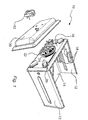
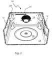
- Figures 1 and 2 show a perspective view of a combined microwave and hot-air circulating cooking appliance 10 according to the present invention from the back and from the front, respectively.
- the figures show the interior of the appliance with the outer casing taken away.
- the ceiling (top wall) of the cooking cavity, as well as the front door has been removed.
- the side walls 12, bottom wall 14 and rear wall 16 of the cavity are shown.
- the cavity comprises inlet ports 18 for feeding microwave energy into the cavity.
- the bottom 14 of the cavity has a circular recess 15 for receiving a turntable or the like.
- a fan 22 Behind a perforated region 20 of the rear wall 16 of the cavity, there is provided a fan 22 surrounded by a heating coil 24. At each corner of the rear wall 16, there is located an air conduit 26 which is connected to an opening 28 into the cooking cavity of the appliance 10.
- a lid 30 is attached to the back side of the rear wall 16 for defining a dedicated air heating compartment.
- a motor 32 for driving the fan 22 is located behind this compartment.
- the fan 22 is rotated in such a sense that is sucks air from the cooking cavity through the perforated central region 20 and into the heating compartment. This air is then forced more or less radially away from the fan 22 and passed through the heating coil 24. In this way, the air is given an elevated temperature. The heated air then enters the air conduits 26 and is directed through the openings 28 in the rear wall 16 back into the cavity. In this way, heating by hot-air circulation is effected.
- the direction of the air flow at the rear wall of the cavity is indicated with arrows in figures 1 and 2.
- Figure 3 is a schematic plan view of the back side of the rear wall 16, showing the air conduits 26 and the central perforated region 20.
- the cross-sectional area of the conduits affect the overall performance.
- the mounting angle of each conduit with respect to the rotation center of the fan is a contributing factor. The mounting angles of the conduits should be selected to guide the injected air towards the ceiling/wall and the bottom/wall, thereby "rectifying" the tangential part of the air leaving the rotating fan wheel, hence reducing the whirl in the air flow inside the cooking cavity.
- a larger flow/velocity of air at the bottom of the cavity compared to the top gives an improved heating evenness.
- an air velocity of 0.5-2.5 m/s through the upper, and 2-6 m/s through the lower injection openings has proven effective.
- each conduit 26 should provide sufficient attenuation for the microwave frequency employed.
- a conduit of circular cross-section with a diameter of just under 70 mm needs to be infinitely long (situation at cut-off for the conduit).
- a smaller diameter would allow a shorter length with maintained microwave sealing. If the diameter would be as small as 5 mm, a length of only 1 mm is required.
- conduit members having a rounded upper part (half pipe) that is elongated in height by straight walls. This is shown in detail in figure 4. These conduit members are attached to the outside of the cavity wall and connected to the injection openings, such that air conduits are formed.
- a width (W) of 25 mm, a height (H) of 25 mm and a length (L) of 30 mm gives a cut-off frequency for the conduit of 5 GHz, and an attenuation of 65 dB at a microwave frequency of 2.45 GHz.
- the conduit members have an open end which is generally directed towards the fan when the conduit members are attached to the back side of the rear cavity wall.
- conduits Opposite the open end, the conduits are terminated in a dead end, in order for the air flow to be directed through the injection openings in the rear wall. It is to be understood, however, that various other designs for the conduits are conceivable within the scope of the invention as defined in the appended claims.
- each conduit member as shown in figure 4 may, for example, be attached to the back of the rear wall by rivets or the like.
- the conduit members have a flange 40 with holes 42 for easy attachment to the cavity wall.
- the air injection openings 28 in the rear wall of the cavity should have a diameter equal to, or smaller than, the width of the conduit 26 connected thereto.
- the diameter of the openings 28 is equal to the width of the conduit 26.
- the openings are placed close to the corners in a respective quadrant of the rear wall (for the case with four openings). The reason for this is that the air flow towards the front door of the oven should be as undisturbed as possible. However, it is conceivable within the scope of the invention to have more or fewer than four openings, as well as other placements thereof.
- Example 1 Conduit Length, L Width, W Height, H Angle, ⁇ 26A 60 mm 26 mm 10 mm 45° 26B 60 mm 26 mm 26 mm 45° 26C 60 mm 26 mm 26 mm 45° 26D 60 mm 26 mm 8 mm 60°
- Example 1 the upper conduits A and D have a smaller height than the lower conduits in order to provide a larger airflow at the bottom of the cooking cavity. To some degree, the whirl produced by the fan is reduced when the air flows through the conduits. However, the final reduction of whirl is obtained by mounting conduit D at a larger angle than the other conduits.
- Example 2 Conduit Length, L Width, W Height, H Angle, ⁇ 26A 60 mm 26 mm 26 mm 45° 26B 60 mm 26 mm 26 mm 45° 26C 60 mm 26 mm 26 mm 45° 26D 60 mm 26 mm 26 mm 72°
- Example 2 all the conduits have the same dimensions. Hence, only one type of conduit member is required for this embodiment. Still, a desired flow of hot air in the cooking cavity can be obtained.
- conduit D is again mounted at a larger angle than the other conduits, in order to provide the final reduction of whirl and obtain the desired heating evenness in the cooking cavity.
- the diameter of each of the injection openings is equal to the width of the conduits, i.e. 26 mm.
- the injection openings for hot air according to the present invention could be provided in any cavity wall, including the bottom wall and the top wall. It is also understood that the hot air could be injected into the cavity through one wall, and sucked out through another wall.
- a combined microwave and hot-air circulating cooking appliance has been disclosed.
- Flow of hot air within a cooking cavity of the appliance is improved by having large-diameter injection openings in a wall of the cavity, through which openings hot air is injected into the cooking cavity.
- an air conduit is connected to each opening.
- Each of the air conduits has such dimensions that propagation of microwave energy at the operational microwave frequency of the appliance through the conduit is prevented.
Landscapes
- Physics & Mathematics (AREA)
- Thermal Sciences (AREA)
- Electromagnetism (AREA)
- Electric Ovens (AREA)
- Constitution Of High-Frequency Heating (AREA)
Abstract
Description
| Example 1 | ||||
| Conduit | Length, L | Width, W | Height, H | Angle, α |
| 26A | 60 | 26 | 10 mm | 45° |
| 26B | 60 | 26 | 26 mm | 45° |
| 26C | 60 | 26 | 26 mm | 45° |
| 26D | 60 | 26 mm | 8 mm | 60° |
| Example 2 | ||||
| Conduit | Length, L | Width, W | Height, H | Angle, α |
| 26A | 60 | 26 | 26 mm | 45° |
| 26B | 60 | 26 | 26 mm | 45° |
| 26C | 60 | 26 | 26 mm | 45° |
| 26D | 60 | 26 | 26 mm | 72° |
Claims (10)
- A combined microwave and hot-air circulating cooking appliance, comprising a cooking cavity for receiving a foodstuff to be heated, a door for providing access to the cooking cavity, a microwave feeding arrangement for feeding microwave energy within a predetermined frequency range into the cooking cavity, a heater for elevating the temperature of air circulating in the cooking cavity, and a fan for circulating the air within said cavity, wherein said heater and said fan are arranged in a dedicated air heating compartment outside the cooking cavity, characterized in that a plurality of air injection openings are provided in a wall of the cavity for injecting heated air into the cooking cavity, wherein each of said injection openings is connected to said heating compartment by means of an air conduit having such dimensions so as to prevent propagation of microwave energy of said predetermined frequency range through said conduit.
- A cooking appliance according to claim 1, wherein each of the air conduits is comprised of a conduit member attached to the outside of said wall.
- A cooking appliance according to any one of the preceding claims, comprising an injection opening in the vicinity of each corner of said wall.
- A cooking appliance according to any one of the preceding claims, wherein said wall further comprises air suction openings for allowing air to flow from the cooking cavity into the heating compartment.
- A cooking appliance according to claim 4, wherein said suction openings are comprised of a perforated region centrally in said wall.
- A cooking appliance according to any one of the preceding claims, wherein each of the air injection openings has a diameter of 10 mm or more, preferably 20 mm or more, and wherein the air conduit to which each opening is connected has a width equal to or larger than the diameter of the injection opening.
- A cooking appliance according to any one of the preceding claims, wherein the length of each of the air conduits is at least 30 mm, preferably about 60 mm.
- A cooking appliance according to claim 2, wherein the conduit member has the form of a half pipe.
- A cooking appliance according to claim 3, wherein the air conduits that connect to injection openings in the upper portion of said wall have a smaller cross-sectional area than the air conduits that connect to openings in the lower portion of the wall.
- A cooking appliance according to claim 3, wherein air conduits are arranged such that the air velocity through the upper openings is 0.5-2.5 m/s, and the air velocity through the lower openings is 2.0-6.0 m/s.
Priority Applications (1)
| Application Number | Priority Date | Filing Date | Title |
|---|---|---|---|
| PL04103668T PL1513375T3 (en) | 2003-09-08 | 2004-07-29 | Microwave oven with convection heating |
Applications Claiming Priority (2)
| Application Number | Priority Date | Filing Date | Title |
|---|---|---|---|
| SE0302407 | 2003-09-08 | ||
| SE0302407A SE525827C2 (en) | 2003-09-08 | 2003-09-08 | Microwave oven with convection heating |
Publications (3)
| Publication Number | Publication Date |
|---|---|
| EP1513375A2 true EP1513375A2 (en) | 2005-03-09 |
| EP1513375A3 EP1513375A3 (en) | 2007-01-24 |
| EP1513375B1 EP1513375B1 (en) | 2008-06-25 |
Family
ID=28787293
Family Applications (1)
| Application Number | Title | Priority Date | Filing Date |
|---|---|---|---|
| EP04103668A Expired - Lifetime EP1513375B1 (en) | 2003-09-08 | 2004-07-29 | Microwave oven with convection heating |
Country Status (8)
| Country | Link |
|---|---|
| US (1) | US6927372B2 (en) |
| EP (1) | EP1513375B1 (en) |
| CN (1) | CN100430654C (en) |
| AT (1) | ATE399450T1 (en) |
| DE (1) | DE602004014566D1 (en) |
| ES (1) | ES2306960T3 (en) |
| PL (1) | PL1513375T3 (en) |
| SE (1) | SE525827C2 (en) |
Cited By (1)
| Publication number | Priority date | Publication date | Assignee | Title |
|---|---|---|---|---|
| DE102014203532A1 (en) * | 2014-02-27 | 2015-08-27 | BSH Hausgeräte GmbH | Microwave oven with a special microwave trap |
Families Citing this family (9)
| Publication number | Priority date | Publication date | Assignee | Title |
|---|---|---|---|---|
| JP2008523352A (en) | 2004-12-14 | 2008-07-03 | イノディス コーポレーション | Impingement / convection / microwave oven and method |
| EP1747917B1 (en) * | 2005-07-28 | 2009-10-21 | ebm-papst St. Georgen GmbH & Co. KG | Heating device |
| US8658944B2 (en) * | 2007-07-12 | 2014-02-25 | Daniel Clemenz | Apparatus and method for melting ice, snow or the like in connection with a furnace |
| US7958796B2 (en) * | 2008-11-12 | 2011-06-14 | Hiwin Technologies Corp. | Screw-driven fan device |
| KR20150020280A (en) | 2012-04-20 | 2015-02-25 | 케이스 웨스턴 리저브 유니버시티 | Composite shape memory materials |
| DE202014005299U1 (en) * | 2014-07-01 | 2015-10-09 | Emilio Reales Bertomeo | Device for heating and / or cooking meat products |
| DE102018117532B4 (en) * | 2018-07-19 | 2020-06-18 | Wiesheu Gmbh | Device for the heat treatment of food |
| US12016107B2 (en) | 2020-03-19 | 2024-06-18 | Texas Research International, Inc. | Continuous mode conveyor cooking utilizing hot air jet impingement and microwave energy |
| CN111904293B (en) * | 2020-07-17 | 2022-04-01 | 广东美的白色家电技术创新中心有限公司 | Cooking device |
Family Cites Families (8)
| Publication number | Priority date | Publication date | Assignee | Title |
|---|---|---|---|---|
| US4337384A (en) * | 1979-08-01 | 1982-06-29 | Matsushita Electric Industrial Co., Ltd. | Cooking appliance of the hot air circulating type |
| FR2637053B1 (en) * | 1988-09-29 | 1990-11-16 | Scholtes Ets Eugen | MIXED COOKING OVEN |
| US5717192A (en) * | 1990-01-10 | 1998-02-10 | Patentsmith Technology, Ltd. | Jet impingement batch oven |
| US5468935A (en) * | 1994-12-10 | 1995-11-21 | Wang; Ching-Hsiang | L-electric conventional roaster oven with whirlpool air circulation |
| WO1999052328A1 (en) * | 1998-04-02 | 1999-10-14 | Turbochef Technologies, Inc. | Residential oven with convectional and microwave heating |
| US6376817B1 (en) * | 1998-10-09 | 2002-04-23 | Turbochef Technologies, Inc. | Compact quick-cooking oven |
| US6049066A (en) * | 1999-03-26 | 2000-04-11 | Wilson; W. Robert | Concentric air delivery and return oven |
| DE10049847B4 (en) * | 2000-04-19 | 2005-12-01 | Lg Electronics Inc. | microwave oven |
-
2003
- 2003-09-08 SE SE0302407A patent/SE525827C2/en not_active IP Right Cessation
-
2004
- 2004-07-29 EP EP04103668A patent/EP1513375B1/en not_active Expired - Lifetime
- 2004-07-29 AT AT04103668T patent/ATE399450T1/en not_active IP Right Cessation
- 2004-07-29 DE DE602004014566T patent/DE602004014566D1/en not_active Expired - Fee Related
- 2004-07-29 ES ES04103668T patent/ES2306960T3/en not_active Expired - Lifetime
- 2004-07-29 PL PL04103668T patent/PL1513375T3/en unknown
- 2004-08-23 US US10/924,134 patent/US6927372B2/en not_active Expired - Lifetime
- 2004-09-08 CN CNB2004100768760A patent/CN100430654C/en not_active Expired - Fee Related
Cited By (1)
| Publication number | Priority date | Publication date | Assignee | Title |
|---|---|---|---|---|
| DE102014203532A1 (en) * | 2014-02-27 | 2015-08-27 | BSH Hausgeräte GmbH | Microwave oven with a special microwave trap |
Also Published As
| Publication number | Publication date |
|---|---|
| SE525827C2 (en) | 2005-05-10 |
| CN1594989A (en) | 2005-03-16 |
| ES2306960T3 (en) | 2008-11-16 |
| EP1513375B1 (en) | 2008-06-25 |
| US6927372B2 (en) | 2005-08-09 |
| DE602004014566D1 (en) | 2008-08-07 |
| ATE399450T1 (en) | 2008-07-15 |
| US20050051540A1 (en) | 2005-03-10 |
| SE0302407L (en) | 2005-03-09 |
| PL1513375T3 (en) | 2008-11-28 |
| EP1513375A3 (en) | 2007-01-24 |
| SE0302407D0 (en) | 2003-09-08 |
| CN100430654C (en) | 2008-11-05 |
Similar Documents
| Publication | Publication Date | Title |
|---|---|---|
| US7049568B2 (en) | Wall-mounted type microwave oven | |
| KR100284548B1 (en) | Installation Structure of Hood Fan for Microwave Oven | |
| EP2015610B1 (en) | Convection heating unit and heating cooker having the same | |
| US6344637B2 (en) | Cooling system for built-in microwave oven | |
| US6864472B2 (en) | Exhaust and ventilation system for mountable type microwave oven | |
| EP1513375B1 (en) | Microwave oven with convection heating | |
| US6218651B1 (en) | Microwave oven | |
| US6861632B2 (en) | Microwave oven | |
| US6689991B2 (en) | Electronic range | |
| EP2235445B1 (en) | A microwave oven | |
| KR100672475B1 (en) | Multi Duct Convection Microwave Oven | |
| US7271373B2 (en) | Microwave oven | |
| US7345261B2 (en) | Wall-mounted microwave oven | |
| CN220551943U (en) | Integrated kitchen | |
| KR100587348B1 (en) | Hooded microwave oven | |
| KR200373471Y1 (en) | Microwave oven | |
| KR100936154B1 (en) | Microwave | |
| KR100936153B1 (en) | Microwave | |
| KR20250138380A (en) | Cooking appliance | |
| KR20240084501A (en) | Cooking appliance | |
| KR20240084499A (en) | Cooking appliance | |
| CN121631334A (en) | Cooking utensils | |
| JPH0348413B2 (en) |
Legal Events
| Date | Code | Title | Description |
|---|---|---|---|
| PUAI | Public reference made under article 153(3) epc to a published international application that has entered the european phase |
Free format text: ORIGINAL CODE: 0009012 |
|
| AK | Designated contracting states |
Kind code of ref document: A2 Designated state(s): AT BE BG CH CY CZ DE DK EE ES FI FR GB GR HU IE IT LI LU MC NL PL PT RO SE SI SK TR |
|
| AX | Request for extension of the european patent |
Extension state: AL HR LT LV MK |
|
| PUAL | Search report despatched |
Free format text: ORIGINAL CODE: 0009013 |
|
| AK | Designated contracting states |
Kind code of ref document: A3 Designated state(s): AT BE BG CH CY CZ DE DK EE ES FI FR GB GR HU IE IT LI LU MC NL PL PT RO SE SI SK TR |
|
| AX | Request for extension of the european patent |
Extension state: AL HR LT LV MK |
|
| 17P | Request for examination filed |
Effective date: 20070709 |
|
| AKX | Designation fees paid |
Designated state(s): AT BE BG CH CY CZ DE DK EE ES FI FR GB GR HU IE IT LI LU MC NL PL PT RO SE SI SK TR |
|
| GRAP | Despatch of communication of intention to grant a patent |
Free format text: ORIGINAL CODE: EPIDOSNIGR1 |
|
| RIN1 | Information on inventor provided before grant (corrected) |
Inventor name: GARCIA-PADRON, RICARDO WHIRLPOOL EUROPE S.R.L. Inventor name: EKINGE, ROLAND WHIRLPOOL EUROPE S.R.L. Inventor name: NYREN, GUNNAR WHIRLPOOL EUROPE S.R.L. |
|
| GRAS | Grant fee paid |
Free format text: ORIGINAL CODE: EPIDOSNIGR3 |
|
| GRAA | (expected) grant |
Free format text: ORIGINAL CODE: 0009210 |
|
| AK | Designated contracting states |
Kind code of ref document: B1 Designated state(s): AT BE BG CH CY CZ DE DK EE ES FI FR GB GR HU IE IT LI LU MC NL PL PT RO SE SI SK TR |
|
| REG | Reference to a national code |
Ref country code: GB Ref legal event code: FG4D |
|
| REG | Reference to a national code |
Ref country code: CH Ref legal event code: EP |
|
| REF | Corresponds to: |
Ref document number: 602004014566 Country of ref document: DE Date of ref document: 20080807 Kind code of ref document: P |
|
| REG | Reference to a national code |
Ref country code: IE Ref legal event code: FG4D |
|
| REG | Reference to a national code |
Ref country code: SE Ref legal event code: TRGR |
|
| PG25 | Lapsed in a contracting state [announced via postgrant information from national office to epo] |
Ref country code: FI Free format text: LAPSE BECAUSE OF FAILURE TO SUBMIT A TRANSLATION OF THE DESCRIPTION OR TO PAY THE FEE WITHIN THE PRESCRIBED TIME-LIMIT Effective date: 20080625 Ref country code: SI Free format text: LAPSE BECAUSE OF FAILURE TO SUBMIT A TRANSLATION OF THE DESCRIPTION OR TO PAY THE FEE WITHIN THE PRESCRIBED TIME-LIMIT Effective date: 20080625 |
|
| REG | Reference to a national code |
Ref country code: ES Ref legal event code: FG2A Ref document number: 2306960 Country of ref document: ES Kind code of ref document: T3 |
|
| PG25 | Lapsed in a contracting state [announced via postgrant information from national office to epo] |
Ref country code: NL Free format text: LAPSE BECAUSE OF FAILURE TO SUBMIT A TRANSLATION OF THE DESCRIPTION OR TO PAY THE FEE WITHIN THE PRESCRIBED TIME-LIMIT Effective date: 20080625 Ref country code: AT Free format text: LAPSE BECAUSE OF FAILURE TO SUBMIT A TRANSLATION OF THE DESCRIPTION OR TO PAY THE FEE WITHIN THE PRESCRIBED TIME-LIMIT Effective date: 20080625 |
|
| REG | Reference to a national code |
Ref country code: PL Ref legal event code: T3 |
|
| NLV1 | Nl: lapsed or annulled due to failure to fulfill the requirements of art. 29p and 29m of the patents act | ||
| PG25 | Lapsed in a contracting state [announced via postgrant information from national office to epo] |
Ref country code: CZ Free format text: LAPSE BECAUSE OF FAILURE TO SUBMIT A TRANSLATION OF THE DESCRIPTION OR TO PAY THE FEE WITHIN THE PRESCRIBED TIME-LIMIT Effective date: 20080625 Ref country code: PT Free format text: LAPSE BECAUSE OF FAILURE TO SUBMIT A TRANSLATION OF THE DESCRIPTION OR TO PAY THE FEE WITHIN THE PRESCRIBED TIME-LIMIT Effective date: 20081125 |
|
| PG25 | Lapsed in a contracting state [announced via postgrant information from national office to epo] |
Ref country code: SK Free format text: LAPSE BECAUSE OF FAILURE TO SUBMIT A TRANSLATION OF THE DESCRIPTION OR TO PAY THE FEE WITHIN THE PRESCRIBED TIME-LIMIT Effective date: 20080625 Ref country code: RO Free format text: LAPSE BECAUSE OF FAILURE TO SUBMIT A TRANSLATION OF THE DESCRIPTION OR TO PAY THE FEE WITHIN THE PRESCRIBED TIME-LIMIT Effective date: 20080625 Ref country code: BE Free format text: LAPSE BECAUSE OF FAILURE TO SUBMIT A TRANSLATION OF THE DESCRIPTION OR TO PAY THE FEE WITHIN THE PRESCRIBED TIME-LIMIT Effective date: 20080625 |
|
| REG | Reference to a national code |
Ref country code: CH Ref legal event code: PL |
|
| PG25 | Lapsed in a contracting state [announced via postgrant information from national office to epo] |
Ref country code: MC Free format text: LAPSE BECAUSE OF NON-PAYMENT OF DUE FEES Effective date: 20080731 |
|
| PG25 | Lapsed in a contracting state [announced via postgrant information from national office to epo] |
Ref country code: EE Free format text: LAPSE BECAUSE OF FAILURE TO SUBMIT A TRANSLATION OF THE DESCRIPTION OR TO PAY THE FEE WITHIN THE PRESCRIBED TIME-LIMIT Effective date: 20080625 Ref country code: DK Free format text: LAPSE BECAUSE OF FAILURE TO SUBMIT A TRANSLATION OF THE DESCRIPTION OR TO PAY THE FEE WITHIN THE PRESCRIBED TIME-LIMIT Effective date: 20080625 Ref country code: BG Free format text: LAPSE BECAUSE OF FAILURE TO SUBMIT A TRANSLATION OF THE DESCRIPTION OR TO PAY THE FEE WITHIN THE PRESCRIBED TIME-LIMIT Effective date: 20080925 |
|
| PLBE | No opposition filed within time limit |
Free format text: ORIGINAL CODE: 0009261 |
|
| STAA | Information on the status of an ep patent application or granted ep patent |
Free format text: STATUS: NO OPPOSITION FILED WITHIN TIME LIMIT |
|
| 26N | No opposition filed |
Effective date: 20090326 |
|
| PG25 | Lapsed in a contracting state [announced via postgrant information from national office to epo] |
Ref country code: CH Free format text: LAPSE BECAUSE OF NON-PAYMENT OF DUE FEES Effective date: 20080731 Ref country code: LI Free format text: LAPSE BECAUSE OF NON-PAYMENT OF DUE FEES Effective date: 20080731 |
|
| PG25 | Lapsed in a contracting state [announced via postgrant information from national office to epo] |
Ref country code: IE Free format text: LAPSE BECAUSE OF NON-PAYMENT OF DUE FEES Effective date: 20080729 |
|
| PGFP | Annual fee paid to national office [announced via postgrant information from national office to epo] |
Ref country code: ES Payment date: 20090727 Year of fee payment: 6 Ref country code: FR Payment date: 20090717 Year of fee payment: 6 |
|
| PGFP | Annual fee paid to national office [announced via postgrant information from national office to epo] |
Ref country code: DE Payment date: 20090729 Year of fee payment: 6 Ref country code: GB Payment date: 20090727 Year of fee payment: 6 Ref country code: SE Payment date: 20090729 Year of fee payment: 6 Ref country code: TR Payment date: 20090708 Year of fee payment: 6 |
|
| PGFP | Annual fee paid to national office [announced via postgrant information from national office to epo] |
Ref country code: IT Payment date: 20090727 Year of fee payment: 6 |
|
| PG25 | Lapsed in a contracting state [announced via postgrant information from national office to epo] |
Ref country code: CY Free format text: LAPSE BECAUSE OF FAILURE TO SUBMIT A TRANSLATION OF THE DESCRIPTION OR TO PAY THE FEE WITHIN THE PRESCRIBED TIME-LIMIT Effective date: 20080625 Ref country code: HU Free format text: LAPSE BECAUSE OF FAILURE TO SUBMIT A TRANSLATION OF THE DESCRIPTION OR TO PAY THE FEE WITHIN THE PRESCRIBED TIME-LIMIT Effective date: 20081226 Ref country code: LU Free format text: LAPSE BECAUSE OF NON-PAYMENT OF DUE FEES Effective date: 20080729 |
|
| PGFP | Annual fee paid to national office [announced via postgrant information from national office to epo] |
Ref country code: PL Payment date: 20100617 Year of fee payment: 7 |
|
| PG25 | Lapsed in a contracting state [announced via postgrant information from national office to epo] |
Ref country code: GR Free format text: LAPSE BECAUSE OF FAILURE TO SUBMIT A TRANSLATION OF THE DESCRIPTION OR TO PAY THE FEE WITHIN THE PRESCRIBED TIME-LIMIT Effective date: 20080926 |
|
| GBPC | Gb: european patent ceased through non-payment of renewal fee |
Effective date: 20100729 |
|
| REG | Reference to a national code |
Ref country code: FR Ref legal event code: ST Effective date: 20110331 |
|
| PG25 | Lapsed in a contracting state [announced via postgrant information from national office to epo] |
Ref country code: DE Free format text: LAPSE BECAUSE OF NON-PAYMENT OF DUE FEES Effective date: 20110201 |
|
| REG | Reference to a national code |
Ref country code: DE Ref legal event code: R119 Ref document number: 602004014566 Country of ref document: DE Effective date: 20110201 |
|
| PG25 | Lapsed in a contracting state [announced via postgrant information from national office to epo] |
Ref country code: FR Free format text: LAPSE BECAUSE OF NON-PAYMENT OF DUE FEES Effective date: 20100802 Ref country code: IT Free format text: LAPSE BECAUSE OF NON-PAYMENT OF DUE FEES Effective date: 20100729 |
|
| PG25 | Lapsed in a contracting state [announced via postgrant information from national office to epo] |
Ref country code: GB Free format text: LAPSE BECAUSE OF NON-PAYMENT OF DUE FEES Effective date: 20100729 |
|
| REG | Reference to a national code |
Ref country code: ES Ref legal event code: FD2A Effective date: 20110818 |
|
| PG25 | Lapsed in a contracting state [announced via postgrant information from national office to epo] |
Ref country code: ES Free format text: LAPSE BECAUSE OF NON-PAYMENT OF DUE FEES Effective date: 20100730 |
|
| PG25 | Lapsed in a contracting state [announced via postgrant information from national office to epo] |
Ref country code: SE Free format text: LAPSE BECAUSE OF NON-PAYMENT OF DUE FEES Effective date: 20100730 |
|
| PG25 | Lapsed in a contracting state [announced via postgrant information from national office to epo] |
Ref country code: PL Free format text: LAPSE BECAUSE OF NON-PAYMENT OF DUE FEES Effective date: 20110729 |
|
| REG | Reference to a national code |
Ref country code: PL Ref legal event code: LAPE |
|
| PG25 | Lapsed in a contracting state [announced via postgrant information from national office to epo] |
Ref country code: TR Free format text: LAPSE BECAUSE OF NON-PAYMENT OF DUE FEES Effective date: 20100729 |