EP1513331B1 - Radiotelephone - Google Patents
Radiotelephone Download PDFInfo
- Publication number
- EP1513331B1 EP1513331B1 EP04105711.8A EP04105711A EP1513331B1 EP 1513331 B1 EP1513331 B1 EP 1513331B1 EP 04105711 A EP04105711 A EP 04105711A EP 1513331 B1 EP1513331 B1 EP 1513331B1
- Authority
- EP
- European Patent Office
- Prior art keywords
- controller
- incoming call
- alerting indicator
- alerting
- volume
- Prior art date
- Legal status (The legal status is an assumption and is not a legal conclusion. Google has not performed a legal analysis and makes no representation as to the accuracy of the status listed.)
- Expired - Lifetime
Links
Images

Classifications
-
- H—ELECTRICITY
- H04—ELECTRIC COMMUNICATION TECHNIQUE
- H04M—TELEPHONIC COMMUNICATION
- H04M19/00—Current supply arrangements for telephone systems
- H04M19/02—Current supply arrangements for telephone systems providing ringing current or supervisory tones, e.g. dialling tone or busy tone
- H04M19/04—Current supply arrangements for telephone systems providing ringing current or supervisory tones, e.g. dialling tone or busy tone the ringing-current being generated at the substations
- H04M19/041—Encoding the ringing signal, i.e. providing distinctive or selective ringing capability
-
- H—ELECTRICITY
- H04—ELECTRIC COMMUNICATION TECHNIQUE
- H04M—TELEPHONIC COMMUNICATION
- H04M1/00—Substation equipment, e.g. for use by subscribers
- H04M1/72—Mobile telephones; Cordless telephones, i.e. devices for establishing wireless links to base stations without route selection
- H04M1/724—User interfaces specially adapted for cordless or mobile telephones
-
- H—ELECTRICITY
- H04—ELECTRIC COMMUNICATION TECHNIQUE
- H04M—TELEPHONIC COMMUNICATION
- H04M19/00—Current supply arrangements for telephone systems
- H04M19/02—Current supply arrangements for telephone systems providing ringing current or supervisory tones, e.g. dialling tone or busy tone
- H04M19/04—Current supply arrangements for telephone systems providing ringing current or supervisory tones, e.g. dialling tone or busy tone the ringing-current being generated at the substations
- H04M19/042—Current supply arrangements for telephone systems providing ringing current or supervisory tones, e.g. dialling tone or busy tone the ringing-current being generated at the substations with variable loudness of the ringing tone, e.g. variable envelope or amplitude of ring signal
-
- H—ELECTRICITY
- H04—ELECTRIC COMMUNICATION TECHNIQUE
- H04M—TELEPHONIC COMMUNICATION
- H04M19/00—Current supply arrangements for telephone systems
- H04M19/02—Current supply arrangements for telephone systems providing ringing current or supervisory tones, e.g. dialling tone or busy tone
- H04M19/04—Current supply arrangements for telephone systems providing ringing current or supervisory tones, e.g. dialling tone or busy tone the ringing-current being generated at the substations
- H04M19/047—Vibrating means for incoming calls
Definitions
- This invention relates generally to radiotelephone receivers and, in particular, to radiotelephones having an alerting indicator with an adjustable volume or level.
- a method for muting an alerting indicator of a radiotelephone comprising the steps recited in claim 1.
- a radiotelephone comprising means for muting an audio alerting indicator, as recited in claim 5.
- Embodiments of the invention may provide a radiotelephone having an alerting indicator volume or level that is capable of being adjusted by a user while an incoming call is being received, that is, while the alerting indicator is being generated.
- a method in accordance with the invention may include a step of increasing the alerting indicator upon the termination of an incoming call signal, upon the elapse of a predetermined time period, and/or in response to information inputted to the controller via the keypad user interface, which information specifies that the alerting indicator volume be increased.
- the invention may also be implemented in radiotelephones employing non-audio alerting indicators, such as, for example, vibrating devices.
- Embodiments of the invention will be described in the context of radiotelephones or mobile terminals that operate in accordance with an analog (FM) mode, and/or a Time Division Multiple Access (TDMA) digital mode of operation.
- the invention may also be employed in a radiotelephone that operates with spread spectrum (SS) and Code Division Multiple Access (CDMA) techniques, such as that described in the IS-95 Interim Standard. That is, the invention can be applied to a wide variety of radiotelephones, and to user communication devices in general, that employ an alerting device to alert a user of an incoming call or message.
- SS spread spectrum
- CDMA Code Division Multiple Access
- an audio alerting indicator also referred to hereinafter as an "alert tone” or an “audible tone”
- the invention is not limited as such.
- the invention can be applied to radiotelephones and to user communication systems that employ any suitable device (e.g., a buzzer or a vibrator) for alerting a user of an incoming call or message.
- any suitable device e.g., a buzzer or a vibrator
- the generation of the alert tone is analogous to the ringing of a conventional telephone when an incoming call is being received.
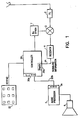
- FIG. 1 illustrates a block diagram of an exemplary receiver portion of a mobile terminal (e.g., IS-136 compatible) that is constructed in accordance with the invention.
- An antenna 1 receives a signal from a base station (not illustrated) indicating an incoming call.
- the received signal which has a center frequency of 885MHz, is fed through a bandpass filter 2 to a mixer 3.
- the receiver's first local oscillator signal is generated with an RX-synthesizer 7 which is tuned above the received frequency by an amount equal to, by example, 45 Mhz.
- the receiver block 4 demodulates and processes the received signal.
- the controller 20 is able to communicate with the receiver block 4 via path 4a by receiving information which is extracted from the received signal by the receiver block 4.In response, the controller 20 sets a flag 20c to enable the generation of an audible tone which indicates an incoming call.
- the audible tone can be generated by programming, over a signalling path 20b, a digital to analog converter (ADC 5a) that forms a portion of an audio processor block 5.
- ADC 5a digital to analog converter
- the required audio processing is accomplished digitally (using the ADC 5a) or in an analog manner, depending on the operating mode.
- the output of the audio processor block 5 drives, by example, a loudspeaker 6 whereby a user is enabled to hear a tone that indicates an occurrence of the incoming call.
- the controller 20 comprises at least one microprocessor (MCU).
- the controller 20 manages the user interface via a keypad 22.
- the controller 20 has a timer 20a for measuring the amount of time which has elapsed from the time when the controller 20 first receives information signalling a particular incoming call from the receiver block 4.
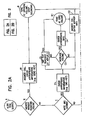
- these options may include: answering the incoming call without muting the alerting indicator volume (Block B); muting the alerting indicator volume before answering the incoming call (Block C); not answering the call but muting the alerting indicator volume (Block D); and not answering the call nor muting the alerting indicator volume (Block E).
- a user of the mobile terminal of Figure 1 may employ the keypad 22 to enter information into the controller 20 as described further below, to choose the desired response option.
- Block C identifies the second response option available to a user in response to an alerting indicator. This option may be implemented in alternate embodiments.
- Block C represents a case wherein the user decides to answer an incoming call after a desired time period has passed. Not wishing to hear the alerting indicator at its original volume during the time period, however, the user desires to reduce or mute the volume.
- the user enters information into a soft key of the keypad 22 (step denoted as Block C1 in Figure 2 ) which causes the controller 20 to set the flag 20c which in turn disables, or mutes, the alerting indicator being produced through the audio processor block 5 and the loudspeaker 6.
- the controller 20 may simply program the ADC 5a with all zeros, or with a value that reduces the analog output of the ADC to zero or approximately zero.
- the output of the ADC 5a may be used to control the gain of an audio path amplifier, or may be used as the source of the alerting indicator itself.
- an oscillator may be used to generate the alerting indicator, and the output of the ADC 5a may be used to control the gain of an amplifier fed by the oscillator, or to disable the oscillator.
- the controller 20 may simply provide a logic level to the audio processor block, such as the output of the flag 20c, wherein the logic level disables logic circuits in the block 5 through which the alerting indicator signal passes.
- Block C2 once the user desires to answer the incoming call, he can simply enter information into the keypad 22 which disables the alerting indicator and enables a voice to be heard over the loudspeaker 6 in the same manner as described above for the first response option.
- the information entered into the keypad 22 (entered by depressing, for example, the SEND-key of keypad 22) also causes the controller 20 to reset the previously set flag 20c. Resetting the flag 20c causes the gain of the block 5, and hence the alerting indicator volume, to subsequently return to their original values.
- the muting, or reduction of the volume may terminate automatically when the call is answered.Thus, an alerting indicator of a subsequent incoming call is sounded by the loudspeaker 6 at the initial volume as set by the initial gain of the audio processor block 5. The step of returning the alerting indicator volume to its original volume in this manner is denoted in Figure 2 by Block R.
- One embodiment of the invention permits the user to maintain the alerting indicator muted. For this case, when the user answers an incoming call, (in the manner described above) the controller 20 is not caused to reset the previously set flag 20C. Thus, the gain of the block 5 and the alerting indicator volume remain muted for subsequent calls until the user intentionally enters information that causes the Flag 20 to be reset. Thereafter, the gain of the audio processing block 5 and the alerting indicator volume return to their original values.
- the user may decide not to answer the incoming call while muting or reducing the original alerting indicator volume.
- the user may accomplish this by employing the same methods used for muting the alerting indicator volume as described in the foregoing discussion of the second response option (Block D1).
- an additional method may be employed to return the alerting indicator volume to its original value, as discussed below for several alternate embodiments.
- the incoming call signal is no longer received by the mobile terminal antenna 1, and the receiver block 4 stops sending extracted signal information to the controller 20.
- the controller 20 may reset the flag 20c, which causes the gain of the audio processor block 5 to increase to its original value. This step is denoted as Block D2 in Figure 2 .
- Block R the alerting indicator volume indicating a subsequent incoming call will be at its original volume
- the mobile terminal may have a capability of redirecting the incoming call to another telephone number or to a voice message storage system.
- the controller 20 sets the timer 20a to run when the controller 20 first receives information from the receiver block 4 representing the incoming call.
- a predetermined value e.g., 30 seconds
- the incoming call signal is still being received, such occurrence, also denoted as Block D2 of Figure 2
- Block D2 of Figure 2 causes the controller 20 to reset the flag 20c.
- Resetting the flag 20c causes the gain of the audio processor block 5 to return to its initial value (Block R) in the same manner as described above for the second response option.
- the incoming call can be simultaneously redirected to a desired destination in a manner known in the art.
- the user may decide to restore the alert tone volume to its original value before the incoming call is terminated and/or before the timer 20a reaches the predetermined value.
- This user response which is denoted as Blocks D3 and D4 of Figure 2 , is similar to the embodiment discussed above under the second response option for restoring the alert tone volume.
- the alert tone volume may be restored by depressing at least one appropriate key of the keypad 22 (e.g., the END-key) which causes the controller to reset the flag 20C. Thereafter, the gain of block 5 and the alert tone volume return to their original values (Block R).
- the fourth response option is denoted in Figure 2 as Block E.
- this option represents a case where the user does not answer or mutethe alerting indicator signal of the incoming call.
- the controller 20 does not set the flag 20c to cause the muting, and the alerting indicator volume is maintained at the original volume during reception of the incoming call.
- the incoming call may be terminated by the user, by the caller, or redirected to a desired destination after the controller timer reaches the predetermined value (Block E1), as described above.
- the teaching of this invention can be employed with any type of alerting device (e.g., loudspeaker, buzzer, vibrator, optical, etc.), wherein it is desired to eliminate the resulting user-perceptible alerting indication (e.g., audible, tactile, visual, etc.) during the receipt of an incoming call to a radiotelephone.
- alerting device e.g., loudspeaker, buzzer, vibrator, optical, etc.
- Reducing the level of alerting device can encompass a reduction in volume, reduction in vibration, reduction in visual output, etc.
Landscapes
- Engineering & Computer Science (AREA)
- Signal Processing (AREA)
- Human Computer Interaction (AREA)
- Computer Networks & Wireless Communication (AREA)
- Mobile Radio Communication Systems (AREA)
- Telephone Function (AREA)
Description
- This invention relates generally to radiotelephone receivers and, in particular, to radiotelephones having an alerting indicator with an adjustable volume or level.
- It is known in the art to provide a radiotelephone with an adjustable alert tone volume, as evidenced by Nokia Mobile Phones owner's manuals N201 and 232. The alert tone is analogous to the ringing of a conventional telephone, and notifies the user of a reception of an incoming call. Such radiotelephones, however, permit a user to select an alert tone volume only during the time when no incoming call is being received by the radiotelephone. For current radiotelephones, in order to quiet an alert tone during the reception of an incoming call a user must either answer and thereafter terminate the call by depressing appropriate keys of a user keypad, or simply turn off the radiotelephone power. Another example is described by the document: "Telephone ring mute with auto re-enable" by M. Spring et al, Motorola Technical Developments, June 1993. These methods, however, are inadequate for a user who does not wish to terminate the call, but desires to either answer the call later, or have the call diverted to a message storage system or other telephone number. To circumvent these problems, some radiotelephones have been provided with a silent service facility, which may include visible alerts such as a flashing LED or display. However, unless the user is viewing the phone, an incoming call may be missed.
- According to a first aspect of the present invention there is provided a method for muting an alerting indicator of a radiotelephone, comprising the steps recited in
claim 1.
According to a second aspect of the present invention there is provided a radiotelephone comprising means for muting an audio alerting indicator, as recited inclaim 5. Embodiments of the invention may provide a radiotelephone having an alerting indicator volume or level that is capable of being adjusted by a user while an incoming call is being received, that is, while the alerting indicator is being generated. - A method in accordance with the invention may include a step of increasing the alerting indicator upon the termination of an incoming call signal, upon the elapse of a predetermined time period, and/or in response to information inputted to the controller via the keypad user interface, which information specifies that the alerting indicator volume be increased.
- A method in accordance with the invention may include a step of maintaining the alerting indicator at a reduced volume for subsequent incoming calls until information is input to the controller via operation of the user interface, which information specifies that the alerting indicator volume be increased. In response to the inputted information the alerting indicator volume is increased.
- The invention may also be implemented in radiotelephones employing non-audio alerting indicators, such as, for example, vibrating devices.
- Embodiments of the invention will now be described, by way of example, with reference to the accompanying drawings, in which:
-
Figure 1 is a block diagram of a receiver portion of a radiotelephone that is constructed and operated in accordance with this invention; and -
Figure 2 is a logical flow diagram of a method in accordance with this invention. - Embodiments of the invention will be described in the context of radiotelephones or mobile terminals that operate in accordance with an analog (FM) mode, and/or a Time Division Multiple Access (TDMA) digital mode of operation. The invention may also be employed in a radiotelephone that operates with spread spectrum (SS) and Code Division Multiple Access (CDMA) techniques, such as that described in the IS-95 Interim Standard. That is, the invention can be applied to a wide variety of radiotelephones, and to user communication devices in general, that employ an alerting device to alert a user of an incoming call or message. It should be realized that although embodiments of the invention are hereinbelow described in the context of radiotelephones that employ an audio alerting indicator (also referred to hereinafter as an "alert tone" or an "audible tone") that is made audible via a loudspeaker 6, the invention is not limited as such. The invention can be applied to radiotelephones and to user communication systems that employ any suitable device (e.g., a buzzer or a vibrator) for alerting a user of an incoming call or message. In the context described hereinbelow, the generation of the alert tone is analogous to the ringing of a conventional telephone when an incoming call is being received.
-
Figure 1 illustrates a block diagram of an exemplary receiver portion of a mobile terminal (e.g., IS-136 compatible) that is constructed in accordance with the invention. Anantenna 1 receives a signal from a base station (not illustrated) indicating an incoming call. The received signal, which has a center frequency of 885MHz, is fed through a bandpass filter 2 to a mixer 3. The receiver's first local oscillator signal is generated with an RX-synthesizer 7 which is tuned above the received frequency by an amount equal to, by example, 45 Mhz. The receiver block 4 demodulates and processes the received signal. Thecontroller 20 is able to communicate with thereceiver block 4 via path 4a by receiving information which is extracted from the received signal by the receiver block 4.In response, thecontroller 20 sets a flag 20c to enable the generation of an audible tone which indicates an incoming call. The audible tone can be generated by programming, over asignalling path 20b, a digital to analog converter (ADC 5a) that forms a portion of anaudio processor block 5. The required audio processing is accomplished digitally (using the ADC 5a) or in an analog manner, depending on the operating mode. The output of theaudio processor block 5 drives, by example, a loudspeaker 6 whereby a user is enabled to hear a tone that indicates an occurrence of the incoming call. - The alerting indicator has a volume or level which may depend upon the amount of gain of at least one amplifier that forms a portion of the
audio processor block 5. The amplifier gain may be varied in response to messages received from thecontroller 20. - The
controller 20 comprises at least one microprocessor (MCU). Thecontroller 20 manages the user interface via akeypad 22. Thecontroller 20 has a timer 20a for measuring the amount of time which has elapsed from the time when thecontroller 20 first receives information signalling a particular incoming call from thereceiver block 4. - For the purposes of this description, there may be various response options available to a user when an alerting indicator is sounded by the mobile terminal indicating an incoming call. Referring to the flow diagram illustrated in
Figure 2 , these options may include: answering the incoming call without muting the alerting indicator volume (Block B); muting the alerting indicator volume before answering the incoming call (Block C); not answering the call but muting the alerting indicator volume (Block D); and not answering the call nor muting the alerting indicator volume (Block E). A user of the mobile terminal ofFigure 1 may employ thekeypad 22 to enter information into thecontroller 20 as described further below, to choose the desired response option. - To implement the first response option (Block B), the user can simply enter information into the
keypad 22 which enables the incoming call to be answered. This step is denoted by Block B1 inFigure 2 . The implementation of this option is not considered germane to the invention and is mentioned for completeness only. Any suitable method known in the art for answering an incoming call enabling the mobile terminal to output the sound of the caller's speech may be employed. Typically, the phone's SEND key is depressed to answer the call. - Block C identifies the second response option available to a user in response to an alerting indicator. This option may be implemented in alternate embodiments. Block C represents a case wherein the user decides to answer an incoming call after a desired time period has passed. Not wishing to hear the alerting indicator at its original volume during the time period, however, the user desires to reduce or mute the volume.
To implement the muting, the user enters information into a soft key of the keypad 22 (step denoted as Block C1 inFigure 2 ) which causes thecontroller 20 to set the flag 20c which in turn disables, or mutes, the alerting indicator being produced through theaudio processor block 5 and the loudspeaker 6. To mute the alerting indicator thecontroller 20 may simply program the ADC 5a with all zeros, or with a value that reduces the analog output of the ADC to zero or approximately zero. - In this regard the output of the ADC 5a may be used to control the gain of an audio path amplifier, or may be used as the source of the alerting indicator itself. In another embodiment an oscillator may be used to generate the alerting indicator, and the output of the ADC 5a may be used to control the gain of an amplifier fed by the oscillator, or to disable the oscillator. It should thus be realized that the exact manner in which the alerting indicator is generated and made audible or otherwise perceptible to the user is not of particular concern to the teaching of this invention. For example, the
controller 20 may simply provide a logic level to the audio processor block, such as the output of the flag 20c, wherein the logic level disables logic circuits in theblock 5 through which the alerting indicator signal passes. - The user may decide to restore the alert tone to its original volume before answering the incoming call (Block C3). In one embodiment of this invention, denoted as Block C4 in
Figure 2 , the user may restore the alert tone volume by depressing at least one appropriate key (e.g., the END-key) of thekeypad 22 which causes thecontroller 20 to reset the previously set flag 20C. Resetting the flag 20C causes the gain of theblock 5, and hence the alert tone volume, to subsequently return to their original values (Block R1). - In another embodiment of this invention, the alert tone volume can be restored to its original value after a predetermined time period has elapsed from when the incoming call was first received. In this case the
controller 20 sets the timer 20a to run when thecontroller 20 first receives information from thereceiver block 4 representing the incoming call. When the timer 20a reaches a predetermined value (e.g., 30 seconds) and the incoming call signal is still being received, such occurrence, also denoted as Block C5 ofFigure 2 , causes thecontroller 20 to reset the flag 20C. The gain ofblock 5 and the alerting tone volume return to their original values (Block R1), as described above for the previously discussed embodiment. - As shown in Block C2, once the user desires to answer the incoming call, he can simply enter information into the
keypad 22 which disables the alerting indicator and enables a voice to be heard over the loudspeaker 6 in the same manner as described above for the first response option. For the case wherein the user answers the incoming call before the alerting indicator volume is restored via one of the two previously discussed embodiments however, the information entered into thekeypad 22, (entered by depressing, for example, the SEND-key of keypad 22) also causes thecontroller 20 to reset the previously set flag 20c. Resetting the flag 20c causes the gain of theblock 5, and hence the alerting indicator volume, to subsequently return to their original values. In this manner, the muting, or reduction of the volume, may terminate automatically when the call is answered.Thus, an alerting indicator of a subsequent incoming call is sounded by the loudspeaker 6 at the initial volume as set by the initial gain of theaudio processor block 5. The step of returning the alerting indicator volume to its original volume in this manner is denoted inFigure 2 by Block R. - In some applications it may be desirable to maintain the alerting indicator muted for subsequent calls. One embodiment of the invention (not illustrated in
Figure 2 ) permits the user to maintain the alerting indicator muted. For this case, when the user answers an incoming call, (in the manner described above) thecontroller 20 is not caused to reset the previously set flag 20C. Thus, the gain of theblock 5 and the alerting indicator volume remain muted for subsequent calls until the user intentionally enters information that causes theFlag 20 to be reset. Thereafter, the gain of theaudio processing block 5 and the alerting indicator volume return to their original values. - As was previously stated, in the third response option, indicated as Block D in
Figure 2 , the user may decide not to answer the incoming call while muting or reducing the original alerting indicator volume. The user may accomplish this by employing the same methods used for muting the alerting indicator volume as described in the foregoing discussion of the second response option (Block D1). However, since the call is not answered by the user, an additional method may be employed to return the alerting indicator volume to its original value, as discussed below for several alternate embodiments. - In a first embodiment, once the incoming call is terminated by the user or by the caller, the incoming call signal is no longer received by the mobile
terminal antenna 1, and thereceiver block 4 stops sending extracted signal information to thecontroller 20. When this occurs, thecontroller 20 may reset the flag 20c, which causes the gain of theaudio processor block 5 to increase to its original value. This step is denoted as Block D2 inFigure 2 . As a result, the alerting indicator volume indicating a subsequent incoming call will be at its original volume (Block R). - The mobile terminal may have a capability of redirecting the incoming call to another telephone number or to a voice message storage system. In these cases the
controller 20 sets the timer 20a to run when thecontroller 20 first receives information from thereceiver block 4 representing the incoming call. When the timer 20a reaches a predetermined value (e.g., 30 seconds), and the incoming call signal is still being received, such occurrence, also denoted as Block D2 ofFigure 2 , causes thecontroller 20 to reset the flag 20c. Resetting the flag 20c causes the gain of theaudio processor block 5 to return to its initial value (Block R) in the same manner as described above for the second response option. Also, the incoming call can be simultaneously redirected to a desired destination in a manner known in the art. - The user may decide to restore the alert tone volume to its original value before the incoming call is terminated and/or before the timer 20a reaches the predetermined value. This user response, which is denoted as Blocks D3 and D4 of
Figure 2 , is similar to the embodiment discussed above under the second response option for restoring the alert tone volume. As such, the alert tone volume may be restored by depressing at least one appropriate key of the keypad 22 (e.g., the END-key) which causes the controller to reset the flag 20C. Thereafter, the gain ofblock 5 and the alert tone volume return to their original values (Block R). - The fourth response option is denoted in
Figure 2 as Block E. As previously stated, this option represents a case where the user does not answer or mutethe alerting indicator signal of the incoming call. In this case, because no alerting indicator muting occurs, thecontroller 20 does not set the flag 20c to cause the muting, and the alerting indicator volume is maintained at the original volume during reception of the incoming call. The incoming call may be terminated by the user, by the caller, or redirected to a desired destination after the controller timer reaches the predetermined value (Block E1), as described above. - Furthermore, and as was described above, the teaching of this invention can be employed with any type of alerting device (e.g., loudspeaker, buzzer, vibrator, optical, etc.), wherein it is desired to eliminate the resulting user-perceptible alerting indication (e.g., audible, tactile, visual, etc.) during the receipt of an incoming call to a radiotelephone. Reducing the level of alerting device can encompass a reduction in volume, reduction in vibration, reduction in visual output, etc.
- Thus, while the invention has been particularly shown and described with respect to preferred embodiments thereof, it will be understood by those skilled in the art that changes in form and details may be made therein without departing from the claimed invention.
Claims (9)
- A method for muting an alerting indicator (6) of a radiotelephone, comprising the steps of:operating a user interface (22) for inputting information via a soft key to a controller (20) of the radiotelephone, the information specifying that the alerting indicator be muted; andin response to the inputted information, muting the alerting indicator (6) while an incoming call is being received,characterized in thatthe alerting indicator is restored to its original value after a predetermined time period has elapsed from when the incoming call was first received.
- A method as set forth in claim 1, wherein when a timer (20a) reaches a predetermined value and the incoming call signal is still being received, such occurrence, causes a controller to reset a flag (20c), wherein resetting the flag causes the gain of an audio processor block (5) and the alert tone volume to subsequently return to their original values.
- A method as set forth in either preceding claim, wherein the alerting indicator is comprised of at least one of a vibration device, an audio device, and an optical device.
- A method as set forth in either preceding claim, wherein the alerting indicator is unmuted automatically when the incoming call is responded to.
- A method as set forth in either preceding claim, wherein the alerting indicator is an alert tone.
- A method as set forth in either preceding claim, further comprising redirecting the incoming call to another telephone number or to a voice message storage system.
- A radiotelephone comprising means for muting of an audio alerting indicator (6), comprising:a RF receiver (4) adapted to receive an incoming call signal;a controller (20) having an input coupled to an output of said receiver, said controller receiving a message indicating the reception of an incoming call signal from said receiver;audio circuit means (5) having an input coupled to an output of said controller, said audio circuit means being responsive to signals received from said controller and adapted to generate an audible alerting indicator, and to vary a volume of said audible alerting indicator; anda user interface (22) including a soft key and other keys adapted to input information to said controller;wherein said controller is responsive to inputted information from the soft key and adapted to signal said audio circuit means to mute the alerting indicator volume in accordance with said inputted information during the reception of the incoming call,characterized in thatsaid controller further comprises timing means having an associated predetermined timeout value, said timing means being adapted to measure the time elapsed from when said controller first receives a message from said receiver indicating the reception of an incoming call, and wherein said controller is adapted to signal said audio circuit means to unmute the alerting indicator when the measured elapsed time equals said predetermined timeout value.
- A radiotelephone as set forth in claim 7, wherein said controller is responsive to a call being terminated and adapted to signal said audio circuit means to unmute the alerting indicator.
- A radiotelephone as set forth in claim 7 or claim 8, and wherein said controller is also responsive to inputted information and adapted to signal said audio circuit means to unmute the alerting indicator to an original volume in accordance with said inputted information.
Applications Claiming Priority (3)
| Application Number | Priority Date | Filing Date | Title |
|---|---|---|---|
| US554277 | 1995-11-06 | ||
| US08/554,277 US6006114A (en) | 1995-11-06 | 1995-11-06 | Radiotelephone enabling adjustment of alerting indicator volume/level during incoming calls |
| EP96307645A EP0772334B1 (en) | 1995-11-06 | 1996-10-22 | Radiotelephone |
Related Parent Applications (3)
| Application Number | Title | Priority Date | Filing Date |
|---|---|---|---|
| EP96307645A Division-Into EP0772334B1 (en) | 1995-11-06 | 1996-10-22 | Radiotelephone |
| EP96307645A Division EP0772334B1 (en) | 1995-11-06 | 1996-10-22 | Radiotelephone |
| EP96307645.0 Division | 1996-10-22 |
Publications (2)
| Publication Number | Publication Date |
|---|---|
| EP1513331A1 EP1513331A1 (en) | 2005-03-09 |
| EP1513331B1 true EP1513331B1 (en) | 2013-06-05 |
Family
ID=24212738
Family Applications (2)
| Application Number | Title | Priority Date | Filing Date |
|---|---|---|---|
| EP96307645A Expired - Lifetime EP0772334B1 (en) | 1995-11-06 | 1996-10-22 | Radiotelephone |
| EP04105711.8A Expired - Lifetime EP1513331B1 (en) | 1995-11-06 | 1996-10-22 | Radiotelephone |
Family Applications Before (1)
| Application Number | Title | Priority Date | Filing Date |
|---|---|---|---|
| EP96307645A Expired - Lifetime EP0772334B1 (en) | 1995-11-06 | 1996-10-22 | Radiotelephone |
Country Status (3)
| Country | Link |
|---|---|
| US (1) | US6006114A (en) |
| EP (2) | EP0772334B1 (en) |
| DE (1) | DE69634115T2 (en) |
Families Citing this family (20)
| Publication number | Priority date | Publication date | Assignee | Title |
|---|---|---|---|---|
| JP3666672B2 (en) | 1994-12-19 | 2005-06-29 | ソニー株式会社 | Communication terminal device |
| JP3606348B2 (en) * | 1997-03-18 | 2005-01-05 | 松下電器産業株式会社 | Wireless communication device |
| US6097964A (en) | 1997-09-04 | 2000-08-01 | Nokia Mobile Phones Limited | Navigation key for a handset |
| US6775361B1 (en) | 1998-05-01 | 2004-08-10 | Canon Kabushiki Kaisha | Recording/playback apparatus with telephone and its control method, video camera with telephone and its control method, image communication apparatus, and storage medium |
| FR2785129B1 (en) * | 1998-10-27 | 2002-04-05 | Sagem | METHOD OF RINGING A MOBILE TELEPHONE |
| WO2000051314A1 (en) * | 1999-02-22 | 2000-08-31 | Sanyo Electric Co., Ltd. | Telephone device mounted in vehicle |
| US6304765B1 (en) * | 1999-11-16 | 2001-10-16 | Motorola, Inc. | Foldable communication device and method |
| DE10045488C2 (en) * | 2000-09-14 | 2002-07-18 | Johann Gross | Acoustic call signaling method for mobile phones and mobile phones |
| US6748210B2 (en) | 2000-12-07 | 2004-06-08 | International Business Machines Corporation | Method and apparatus for automatically terminating to a voice mail an incoming call made to a radio telephone |
| JP4728537B2 (en) * | 2001-09-14 | 2011-07-20 | 株式会社ホンダアクセス | Bluetooth communication system |
| US6999731B2 (en) * | 2001-11-27 | 2006-02-14 | Intel Corporation | Control of an alert mechanism by communication of an event-associated command |
| US7149512B2 (en) * | 2002-06-25 | 2006-12-12 | Intel Corporation | Apparatus and method to automatically adjust volume or control operation of an appliance |
| US6888935B1 (en) | 2003-01-15 | 2005-05-03 | Cisco Technology, Inc. | Speak-louder signaling system for conference calls |
| TWI241117B (en) * | 2003-06-11 | 2005-10-01 | Benq Corp | Method for managing a calling in on a cellular phone |
| KR100575926B1 (en) * | 2003-08-23 | 2006-05-02 | 삼성전자주식회사 | Call reception notification control method of mobile terminal |
| US8001623B2 (en) * | 2005-05-26 | 2011-08-23 | Gertsch Jeffrey H | Electronic helmet |
| JP3996611B2 (en) * | 2005-08-29 | 2007-10-24 | Necインフロンティア株式会社 | Voice call system for computer terminals |
| US20080126930A1 (en) * | 2006-06-28 | 2008-05-29 | Research In Motion Limited | Method and apparatus for dynamically varying one or more properties of a display element in response to variation in an associated characteristic |
| US20080075271A1 (en) * | 2006-09-08 | 2008-03-27 | International Business Machines Corporation | Configurable phone option to increase or decrease ring tone volumes |
| US10271873B2 (en) | 2015-10-26 | 2019-04-30 | Medtronic Vascular, Inc. | Sheathless guide catheter assembly |
Family Cites Families (19)
| Publication number | Priority date | Publication date | Assignee | Title |
|---|---|---|---|---|
| US4495652A (en) * | 1983-02-28 | 1985-01-22 | General Electric Company | Control arrangement for radio apparatus |
| US4523058A (en) * | 1983-10-24 | 1985-06-11 | Uniden Corporation Of America | Ringer signal wave shaping circuit |
| JPS60242738A (en) * | 1984-05-17 | 1985-12-02 | Sony Corp | Cordless telephone set |
| JPS6170841A (en) * | 1984-09-13 | 1986-04-11 | Hashimoto Corp | Telephone automatic response recording device with ease of operation |
| EP0275193B1 (en) * | 1987-01-16 | 1994-12-14 | Nec Corporation | Telephone having receive call indicating function and mute/light key |
| US4924193A (en) * | 1987-01-30 | 1990-05-08 | Nec Corporation | Volume control circuit for use in portable telephone or the like |
| JPH03297232A (en) * | 1990-01-31 | 1991-12-27 | Nec Corp | Call circuit for portable telephone set |
| AU7216991A (en) * | 1990-02-08 | 1991-09-03 | Chesilvale Electronics Limited | Programmable telephone |
| US5392338A (en) * | 1990-03-28 | 1995-02-21 | Danish International, Inc. | Entry of alphabetical characters into a telephone system using a conventional telephone keypad |
| GB2243117B (en) * | 1990-04-20 | 1994-04-20 | Technophone Ltd | Portable radio telephone |
| US5191607A (en) * | 1990-10-09 | 1993-03-02 | Motorola, Inc. | Ring tone muting with disable |
| JP3126377B2 (en) * | 1990-11-28 | 2001-01-22 | 株式会社東芝 | Key telephone equipment |
| US5491745A (en) * | 1991-02-20 | 1996-02-13 | Uniden America Corporation | Method and apparatus for a dual mode keypad permitting one-touch telephone number dialing |
| EP0502617B1 (en) * | 1991-03-06 | 1998-04-15 | Nokia Mobile Phones (U.K.) Limited | Portable telephone |
| GB2269500B (en) * | 1992-07-02 | 1996-02-07 | Motorola Israel Ltd | Radio communications device |
| US5404582A (en) * | 1992-11-27 | 1995-04-04 | Motorola, Inc. | Aural annunciator circuit for a receiver |
| FI92782C (en) * | 1993-02-09 | 1994-12-27 | Nokia Mobile Phones Ltd | Grouping mobile phone settings |
| US5657372A (en) * | 1994-10-17 | 1997-08-12 | Ericsson Inc. | Systems and methods for selectively accepting telephone calls without establishing voice communications |
| JP3550207B2 (en) * | 1995-03-01 | 2004-08-04 | 富士通株式会社 | Mode switching telephone and mode setting method in the telephone |
-
1995
- 1995-11-06 US US08/554,277 patent/US6006114A/en not_active Expired - Lifetime
-
1996
- 1996-10-22 DE DE69634115T patent/DE69634115T2/en not_active Expired - Lifetime
- 1996-10-22 EP EP96307645A patent/EP0772334B1/en not_active Expired - Lifetime
- 1996-10-22 EP EP04105711.8A patent/EP1513331B1/en not_active Expired - Lifetime
Also Published As
| Publication number | Publication date |
|---|---|
| DE69634115D1 (en) | 2005-02-03 |
| EP0772334A2 (en) | 1997-05-07 |
| EP0772334A3 (en) | 1999-03-17 |
| US6006114A (en) | 1999-12-21 |
| EP0772334B1 (en) | 2004-12-29 |
| DE69634115T2 (en) | 2006-02-23 |
| EP1513331A1 (en) | 2005-03-09 |
Similar Documents
| Publication | Publication Date | Title |
|---|---|---|
| EP1513331B1 (en) | Radiotelephone | |
| EP0310379B1 (en) | Radio telephone apparatus | |
| USRE39231E1 (en) | Communication terminal equipment and call incoming control method | |
| US7133503B2 (en) | Incoming call control by the called party | |
| US20030013495A1 (en) | Adaptive audible alert volume control | |
| US5191607A (en) | Ring tone muting with disable | |
| KR20010056261A (en) | Method for receiving called call and rejecting it selectively in portable radio telephone | |
| US7483721B1 (en) | Communication device providing diverse audio signals to indicate receipt of a call or message | |
| KR100345535B1 (en) | Method for automatically transmitting a character message in mobile terminal | |
| KR100506246B1 (en) | How to display caller information, including caller name of communication terminal | |
| US5493603A (en) | Radio telephone set for digital communication which alerts the user of incoming digital data signals | |
| US6370366B2 (en) | Telephony device comprising a base station and at least a subscriber unit, subscriber unit for such a telephony device and method used in such a telephony device | |
| KR20010057247A (en) | Method for classification alert melody that sender of a short message service in mobile phone | |
| KR100584362B1 (en) | How to mute reception status in wireless communication terminal | |
| JP2004072313A (en) | Mobile portable terminal, and incoming call report means switching system therefor | |
| JP3981995B2 (en) | Communication terminal device | |
| JP3485827B2 (en) | Telephone equipment | |
| KR100267863B1 (en) | Method for confirming voice message in digital radio telephone having pager | |
| KR100439224B1 (en) | A device and a operating method of cid for manner mode mobile phone | |
| JP3448488B2 (en) | Portable telephone terminal | |
| JP3037086B2 (en) | Digital cordless telephone | |
| JPH09261300A (en) | Incoming tone quality adjustment circuit for portable telephone set | |
| JPH04271619A (en) | Incoming tone control system for mobile radio equipment | |
| JPH0244419B2 (en) | ||
| JP2002199063A (en) | Communication terminal equipment |
Legal Events
| Date | Code | Title | Description |
|---|---|---|---|
| PUAI | Public reference made under article 153(3) epc to a published international application that has entered the european phase |
Free format text: ORIGINAL CODE: 0009012 |
|
| 17P | Request for examination filed |
Effective date: 20041111 |
|
| AC | Divisional application: reference to earlier application |
Ref document number: 0772334 Country of ref document: EP Kind code of ref document: P |
|
| AK | Designated contracting states |
Kind code of ref document: A1 Designated state(s): DE FR GB SE |
|
| RIN1 | Information on inventor provided before grant (corrected) |
Inventor name: LIETSALMI, MIKKO Inventor name: VANTTILA, JAAKKO Inventor name: SEPPANEN, JORMA A Inventor name: VAIHOJA, JUHA |
|
| RIN1 | Information on inventor provided before grant (corrected) |
Inventor name: VAIHOJA, JUHA Inventor name: SEPPAENEN, JORMA A. Inventor name: VANTTILA, JAAKKO Inventor name: LIETSALMI, MIKKO |
|
| AKX | Designation fees paid |
Designated state(s): DE FR GB SE |
|
| 17Q | First examination report despatched |
Effective date: 20100816 |
|
| GRAP | Despatch of communication of intention to grant a patent |
Free format text: ORIGINAL CODE: EPIDOSNIGR1 |
|
| RAP1 | Party data changed (applicant data changed or rights of an application transferred) |
Owner name: MOBILEMEDIA IDEAS LLC |
|
| GRAS | Grant fee paid |
Free format text: ORIGINAL CODE: EPIDOSNIGR3 |
|
| GRAA | (expected) grant |
Free format text: ORIGINAL CODE: 0009210 |
|
| AC | Divisional application: reference to earlier application |
Ref document number: 0772334 Country of ref document: EP Kind code of ref document: P |
|
| AK | Designated contracting states |
Kind code of ref document: B1 Designated state(s): DE FR GB SE |
|
| REG | Reference to a national code |
Ref country code: GB Ref legal event code: FG4D |
|
| REG | Reference to a national code |
Ref country code: DE Ref legal event code: R096 Ref document number: 69638579 Country of ref document: DE Effective date: 20130801 |
|
| PG25 | Lapsed in a contracting state [announced via postgrant information from national office to epo] |
Ref country code: SE Free format text: LAPSE BECAUSE OF FAILURE TO SUBMIT A TRANSLATION OF THE DESCRIPTION OR TO PAY THE FEE WITHIN THE PRESCRIBED TIME-LIMIT Effective date: 20130605 |
|
| PLBE | No opposition filed within time limit |
Free format text: ORIGINAL CODE: 0009261 |
|
| STAA | Information on the status of an ep patent application or granted ep patent |
Free format text: STATUS: NO OPPOSITION FILED WITHIN TIME LIMIT |
|
| 26N | No opposition filed |
Effective date: 20140306 |
|
| REG | Reference to a national code |
Ref country code: DE Ref legal event code: R097 Ref document number: 69638579 Country of ref document: DE Effective date: 20140306 |
|
| REG | Reference to a national code |
Ref country code: FR Ref legal event code: PLFP Year of fee payment: 20 |
|
| PGFP | Annual fee paid to national office [announced via postgrant information from national office to epo] |
Ref country code: FR Payment date: 20150908 Year of fee payment: 20 |
|
| PGFP | Annual fee paid to national office [announced via postgrant information from national office to epo] |
Ref country code: GB Payment date: 20151021 Year of fee payment: 20 Ref country code: DE Payment date: 20151013 Year of fee payment: 20 |
|
| REG | Reference to a national code |
Ref country code: DE Ref legal event code: R071 Ref document number: 69638579 Country of ref document: DE |
|
| REG | Reference to a national code |
Ref country code: GB Ref legal event code: PE20 Expiry date: 20161021 |
|
| PG25 | Lapsed in a contracting state [announced via postgrant information from national office to epo] |
Ref country code: GB Free format text: LAPSE BECAUSE OF EXPIRATION OF PROTECTION Effective date: 20161021 |