EP1513141A2 - Optical pickup apparatus, optical disk apparatus and optical pickup adjustment method - Google Patents
Optical pickup apparatus, optical disk apparatus and optical pickup adjustment method Download PDFInfo
- Publication number
- EP1513141A2 EP1513141A2 EP04292130A EP04292130A EP1513141A2 EP 1513141 A2 EP1513141 A2 EP 1513141A2 EP 04292130 A EP04292130 A EP 04292130A EP 04292130 A EP04292130 A EP 04292130A EP 1513141 A2 EP1513141 A2 EP 1513141A2
- Authority
- EP
- European Patent Office
- Prior art keywords
- optical pickup
- optical
- optical disk
- base plate
- signal
- Prior art date
- Legal status (The legal status is an assumption and is not a legal conclusion. Google has not performed a legal analysis and makes no representation as to the accuracy of the status listed.)
- Withdrawn
Links
Images








Classifications
-
- G—PHYSICS
- G11—INFORMATION STORAGE
- G11B—INFORMATION STORAGE BASED ON RELATIVE MOVEMENT BETWEEN RECORD CARRIER AND TRANSDUCER
- G11B7/00—Recording or reproducing by optical means, e.g. recording using a thermal beam of optical radiation by modifying optical properties or the physical structure, reproducing using an optical beam at lower power by sensing optical properties; Record carriers therefor
- G11B7/08—Disposition or mounting of heads or light sources relatively to record carriers
- G11B7/09—Disposition or mounting of heads or light sources relatively to record carriers with provision for moving the light beam or focus plane for the purpose of maintaining alignment of the light beam relative to the record carrier during transducing operation, e.g. to compensate for surface irregularities of the latter or for track following
-
- G—PHYSICS
- G11—INFORMATION STORAGE
- G11B—INFORMATION STORAGE BASED ON RELATIVE MOVEMENT BETWEEN RECORD CARRIER AND TRANSDUCER
- G11B7/00—Recording or reproducing by optical means, e.g. recording using a thermal beam of optical radiation by modifying optical properties or the physical structure, reproducing using an optical beam at lower power by sensing optical properties; Record carriers therefor
- G11B7/08—Disposition or mounting of heads or light sources relatively to record carriers
- G11B7/085—Disposition or mounting of heads or light sources relatively to record carriers with provision for moving the light beam into, or out of, its operative position or across tracks, otherwise than during the transducing operation, e.g. for adjustment or preliminary positioning or track change or selection
- G11B7/0857—Arrangements for mechanically moving the whole head
- G11B7/08576—Swinging-arm positioners
-
- G—PHYSICS
- G11—INFORMATION STORAGE
- G11B—INFORMATION STORAGE BASED ON RELATIVE MOVEMENT BETWEEN RECORD CARRIER AND TRANSDUCER
- G11B7/00—Recording or reproducing by optical means, e.g. recording using a thermal beam of optical radiation by modifying optical properties or the physical structure, reproducing using an optical beam at lower power by sensing optical properties; Record carriers therefor
- G11B7/08—Disposition or mounting of heads or light sources relatively to record carriers
- G11B7/085—Disposition or mounting of heads or light sources relatively to record carriers with provision for moving the light beam into, or out of, its operative position or across tracks, otherwise than during the transducing operation, e.g. for adjustment or preliminary positioning or track change or selection
- G11B7/08505—Methods for track change, selection or preliminary positioning by moving the head
- G11B7/08523—Methods for track change, selection or preliminary positioning by moving the head with both tracking and focusing pull-in
-
- G—PHYSICS
- G11—INFORMATION STORAGE
- G11B—INFORMATION STORAGE BASED ON RELATIVE MOVEMENT BETWEEN RECORD CARRIER AND TRANSDUCER
- G11B7/00—Recording or reproducing by optical means, e.g. recording using a thermal beam of optical radiation by modifying optical properties or the physical structure, reproducing using an optical beam at lower power by sensing optical properties; Record carriers therefor
- G11B7/08—Disposition or mounting of heads or light sources relatively to record carriers
- G11B7/09—Disposition or mounting of heads or light sources relatively to record carriers with provision for moving the light beam or focus plane for the purpose of maintaining alignment of the light beam relative to the record carrier during transducing operation, e.g. to compensate for surface irregularities of the latter or for track following
- G11B7/0925—Electromechanical actuators for lens positioning
- G11B7/0927—Electromechanical actuators for lens positioning for focusing only
-
- G—PHYSICS
- G11—INFORMATION STORAGE
- G11B—INFORMATION STORAGE BASED ON RELATIVE MOVEMENT BETWEEN RECORD CARRIER AND TRANSDUCER
- G11B7/00—Recording or reproducing by optical means, e.g. recording using a thermal beam of optical radiation by modifying optical properties or the physical structure, reproducing using an optical beam at lower power by sensing optical properties; Record carriers therefor
- G11B7/08—Disposition or mounting of heads or light sources relatively to record carriers
- G11B7/09—Disposition or mounting of heads or light sources relatively to record carriers with provision for moving the light beam or focus plane for the purpose of maintaining alignment of the light beam relative to the record carrier during transducing operation, e.g. to compensate for surface irregularities of the latter or for track following
- G11B7/094—Methods and circuits for servo offset compensation
-
- G—PHYSICS
- G11—INFORMATION STORAGE
- G11B—INFORMATION STORAGE BASED ON RELATIVE MOVEMENT BETWEEN RECORD CARRIER AND TRANSDUCER
- G11B7/00—Recording or reproducing by optical means, e.g. recording using a thermal beam of optical radiation by modifying optical properties or the physical structure, reproducing using an optical beam at lower power by sensing optical properties; Record carriers therefor
- G11B7/08—Disposition or mounting of heads or light sources relatively to record carriers
- G11B7/09—Disposition or mounting of heads or light sources relatively to record carriers with provision for moving the light beam or focus plane for the purpose of maintaining alignment of the light beam relative to the record carrier during transducing operation, e.g. to compensate for surface irregularities of the latter or for track following
- G11B7/095—Disposition or mounting of heads or light sources relatively to record carriers with provision for moving the light beam or focus plane for the purpose of maintaining alignment of the light beam relative to the record carrier during transducing operation, e.g. to compensate for surface irregularities of the latter or for track following specially adapted for discs, e.g. for compensation of eccentricity or wobble
-
- G—PHYSICS
- G11—INFORMATION STORAGE
- G11B—INFORMATION STORAGE BASED ON RELATIVE MOVEMENT BETWEEN RECORD CARRIER AND TRANSDUCER
- G11B7/00—Recording or reproducing by optical means, e.g. recording using a thermal beam of optical radiation by modifying optical properties or the physical structure, reproducing using an optical beam at lower power by sensing optical properties; Record carriers therefor
- G11B7/12—Heads, e.g. forming of the optical beam spot or modulation of the optical beam
- G11B7/122—Flying-type heads, e.g. analogous to Winchester type in magnetic recording
-
- G—PHYSICS
- G11—INFORMATION STORAGE
- G11B—INFORMATION STORAGE BASED ON RELATIVE MOVEMENT BETWEEN RECORD CARRIER AND TRANSDUCER
- G11B7/00—Recording or reproducing by optical means, e.g. recording using a thermal beam of optical radiation by modifying optical properties or the physical structure, reproducing using an optical beam at lower power by sensing optical properties; Record carriers therefor
- G11B7/12—Heads, e.g. forming of the optical beam spot or modulation of the optical beam
- G11B7/123—Integrated head arrangements, e.g. with source and detectors mounted on the same substrate
-
- G—PHYSICS
- G11—INFORMATION STORAGE
- G11B—INFORMATION STORAGE BASED ON RELATIVE MOVEMENT BETWEEN RECORD CARRIER AND TRANSDUCER
- G11B7/00—Recording or reproducing by optical means, e.g. recording using a thermal beam of optical radiation by modifying optical properties or the physical structure, reproducing using an optical beam at lower power by sensing optical properties; Record carriers therefor
- G11B7/12—Heads, e.g. forming of the optical beam spot or modulation of the optical beam
- G11B7/135—Means for guiding the beam from the source to the record carrier or from the record carrier to the detector
- G11B7/1372—Lenses
- G11B7/1374—Objective lenses
-
- G—PHYSICS
- G11—INFORMATION STORAGE
- G11B—INFORMATION STORAGE BASED ON RELATIVE MOVEMENT BETWEEN RECORD CARRIER AND TRANSDUCER
- G11B7/00—Recording or reproducing by optical means, e.g. recording using a thermal beam of optical radiation by modifying optical properties or the physical structure, reproducing using an optical beam at lower power by sensing optical properties; Record carriers therefor
- G11B7/12—Heads, e.g. forming of the optical beam spot or modulation of the optical beam
- G11B7/135—Means for guiding the beam from the source to the record carrier or from the record carrier to the detector
- G11B7/1372—Lenses
- G11B7/1376—Collimator lenses
-
- G—PHYSICS
- G11—INFORMATION STORAGE
- G11B—INFORMATION STORAGE BASED ON RELATIVE MOVEMENT BETWEEN RECORD CARRIER AND TRANSDUCER
- G11B7/00—Recording or reproducing by optical means, e.g. recording using a thermal beam of optical radiation by modifying optical properties or the physical structure, reproducing using an optical beam at lower power by sensing optical properties; Record carriers therefor
- G11B7/12—Heads, e.g. forming of the optical beam spot or modulation of the optical beam
- G11B7/135—Means for guiding the beam from the source to the record carrier or from the record carrier to the detector
- G11B7/1392—Means for controlling the beam wavefront, e.g. for correction of aberration
- G11B7/13925—Means for controlling the beam wavefront, e.g. for correction of aberration active, e.g. controlled by electrical or mechanical means
-
- G—PHYSICS
- G11—INFORMATION STORAGE
- G11B—INFORMATION STORAGE BASED ON RELATIVE MOVEMENT BETWEEN RECORD CARRIER AND TRANSDUCER
- G11B7/00—Recording or reproducing by optical means, e.g. recording using a thermal beam of optical radiation by modifying optical properties or the physical structure, reproducing using an optical beam at lower power by sensing optical properties; Record carriers therefor
- G11B7/12—Heads, e.g. forming of the optical beam spot or modulation of the optical beam
- G11B7/22—Apparatus or processes for the manufacture of optical heads, e.g. assembly
-
- G—PHYSICS
- G11—INFORMATION STORAGE
- G11B—INFORMATION STORAGE BASED ON RELATIVE MOVEMENT BETWEEN RECORD CARRIER AND TRANSDUCER
- G11B7/00—Recording or reproducing by optical means, e.g. recording using a thermal beam of optical radiation by modifying optical properties or the physical structure, reproducing using an optical beam at lower power by sensing optical properties; Record carriers therefor
- G11B7/08—Disposition or mounting of heads or light sources relatively to record carriers
- G11B7/09—Disposition or mounting of heads or light sources relatively to record carriers with provision for moving the light beam or focus plane for the purpose of maintaining alignment of the light beam relative to the record carrier during transducing operation, e.g. to compensate for surface irregularities of the latter or for track following
- G11B7/0943—Methods and circuits for performing mathematical operations on individual detector segment outputs
Definitions
- This invention relates to an optical pickup apparatus, an optical disk apparatus and an optical pickup adjustment method for recording or reproducing an information signal on or from various optical disks.
- FIG. 17 schematically shows a cross section of a typical one of related-art optical pickups.
- the optical pickup is disclosed in Japanese Patent Laid-Open No. 2003-233921.
- the optical pickup shown is formed as one package wherein an entire optical system is integrated in a floating slider 1120 supported on a load beam 1110 including a bimorph type piezoelectric element 1111.
- the floating slider 1120 has a laminated piezoelectric element 1121 provided on an outer periphery thereof and includes an integrated optical system 1122, a semiconductor laser element 1123 and so forth disposed within the space surrounded by the laminated piezoelectric element 1121. Further, an objective lens 1124 opposing to an optical disk 1130 is disposed above the integrated optical system 1122, semiconductor laser element 1123 and so forth.
- the distance between the integrated optical system 1122 and the objective lens 1124 is changed by the laminated piezoelectric element 1121 to perform a focusing servo operation.
- the load pressure to be applied to the floating slider 1120 can be controlled by the bimorph type piezoelectric element 1111 provided on the load beam 1110 to change the floating amount of the floating slider 1120 to perform a focusing servo operation.
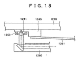
- FIG. 18 shows a cross section of another typical one of related-art optical pickups.
- the optical pickup shown includes a floating slider 1240 disposed above an optical pickup body 1260 by means of a suspension 1261 and an MEMS (micro-electro-mechanical system) actuator 1250 for driving an objective lens 1241 provided on the floating slider 1240 to perform a focusing servo operation for an optical disk 1270.
- MEMS micro-electro-mechanical system
- the stroke of the laminated piezoelectric element 1121 is approximately 2 to 3 ⁇ m or less to the greatest where the laminated piezoelectric element 1121 is used for a thin portion such as the floating slider 1120.
- the focusing servo operation by the load beam 1110 is restricted by the floating amount, and therefore, it is estimated that the stroke is approximately ⁇ 1 ⁇ m or less.
- a voltage of approximately 30 to 100 V is required.
- optical disk drives usually use 12 V or 5 V driving, a DC-DC converter for exclusive use must be provided. Also the cost of the piezoelectric element itself is high.
- the MEMS actuator 1250 since usually the driving force of the MEMS actuator 1250 is low, a sufficient acceleration cannot be obtained to drive the objective lens 1241. Further, since the stroke of movement of the objective lens 1241 is small, the correction amount for an out-of focus state is approximately 2 to 3 ⁇ m or less similarly as in the example described above. Further, since a sufficient acceleration cannot be obtained, a focusing servo operation in a high frequency band cannot be performed. Furthermore, the MEMS still requires a high cost as a driving element for an actuator.
- an optical pickup apparatus including an integrated optical pickup unit for recording or reproducing a signal on or from an optical disk, the integrated optical pickup unit including a semiconductor laser for emitting a light beam and an optical system for introducing the light beam, and a swing arm unit for supporting the integrated optical pickup unit, the swing arm unit including an optical pickup base plate formed from a thin metal plate having a hole for arrangement of the integrated optical pickup unit formed at an end portion thereof, a semiconductor substrate having the integrated optical pickup unit mounted thereon and mounted on one of faces of the optical pickup base plate to close up the hole of the optical pickup base plate, and a transparent cover mounted on the other face of the optical pickup base plate to close up the hole, the integrated optical pickup unit on the semiconductor substrate being disposed in a space formed in the hole of the optical pickup base plate closed up with the semiconductor substrate and the transparent cover.
- an optical disk apparatus including an optical disk driving unit for holding and driving an optical disk to rotate, an integrated optical pickup unit for recording or reproducing a signal on or from the optical disk, the integrated optical pickup unit including a semiconductor laser for emitting a light beam and an optical system for introducing the light beam, and a swing arm unit for supporting the integrated optical pickup unit, the swing arm unit including an optical pickup base plate formed from a thin metal plate having a hole for arrangement of the integrated optical pickup unit formed at an end portion thereof, a semiconductor substrate having the integrated optical pickup unit mounted thereon and mounted on one of faces of the optical pickup base plate to close up the hole of the optical pickup base plate, and a transparent cover mounted on the other face of the optical pickup base plate to close up the hole, the integrated optical pickup unit on the semiconductor substrate being disposed in a space formed in the hole of the optical pickup base plate closed up with the semiconductor substrate and the transparent cover.
- the optical pickup apparatus With the optical pickup apparatus and the optical disk apparatus, since the hole formed in the optical pickup base plate of the swing arm unit is closed up with the semiconductor substrate on which the integrated optical pickup unit is mounted and the transparent cover, and the integrated optical pickup unit is disposed in the closed up space formed in the hole. Consequently, reduction in thickness of the optical pickup can be anticipated. Further, the optical pickup base plate functions as a heat radiating plate, and consequently, improvement in heat radiation from the semiconductor laser can be anticipated. Further, the configuration is simple, and consequently, reduction in number of parts and in cost can be anticipated.
- an optical disk apparatus including an optical pickup for illuminating a light beam upon an optical disk to record or reproduce a signal on or from the optical disk, and a swing arm unit for supporting the optical pickup, the swing arm unit including an optical pickup base plate for holding an integrated optical pickup unit including a semiconductor laser and an optical system, a plate-like support spring disposed in parallel to and along a face of the optical pickup base plate adjacent the optical disk, and a suspension disposed in parallel to and along a face of the support spring adjacent the optical disk, the integrated optical pickup unit including a concave lens for increasing the diversion angle of the laser beam emitted from the optical pickup, the support spring including a collimator lens for converting the laser beam from the concave lens into parallel light, the suspension including a floating slider in which an objective lens for condensing the laser light from the collimator lens on the optical disk is incorporated.
- the support spring and the suspension are provided in parallel to the optical pickup base plate on which the integrated optical pickup unit is held, and the concave lens for increasing the diversion angle of the laser beam emitted from the optical pickup is provided on the integrated optical pickup unit.
- the collimator lens for converting the light from the concave lens into parallel light is provided on the support spring, and the floating slider in which the object lens is incorporated is provided on the suspension. Consequently, the collimator lens can be displaced freely, and the distance for correction of the focus and the acceleration in the focusing servo can be increased. Further, the configuration is simple, and consequently, reduction in number of parts and in cost can be anticipated.
- an optical disk apparatus including an optical pickup for illuminating a light beam upon an optical disk to record or reproduce a signal on or from the optical disk, a moving unit for moving the optical pickup along a signal recording face of the optical disk, and a flexible substrate for supplying a signal to the optical pickup, the flexible substrate having a wiring pattern wherein signal lines necessary for operation of the optical pickup and signal lines necessary only for adjustment of the optical pickup are disposed separately from each other.
- the wiring pattern wherein the signal lines necessary for operation of the optical pickup and the signal lines necessary only for adjustment of the optical pickup are disposed separately from each other is provided on the flexible substrate for supplying a signal to the optical pickup. Consequently, the signal lines necessary for normal operation of the optical pickup and the signal lines necessary only for adjustment of the optical pickup can be handled readily and appropriately and separately from each other. Consequently, assembly and adjustment of the optical disk apparatus are facilitated, and also an error in working can be prevented effectively.
- an optical pickup adjustment method for an optical disk apparatus which includes an optical pickup for illuminating a light beam upon an optical disk to record or reproduce a signal on or from the optical disk, a moving unit for moving the optical pickup along a signal recording face of the optical disk, and a flexible substrate for supplying a signal to the optical pickup
- the optical pickup adjustment method including the steps of providing, on the flexible substrate, a wiring pattern wherein signal lines necessary for operation of the optical pickup and signal lines necessary only for adjustment of the optical pickup are disposed separately from each other, using the signal lines provided on the flexible substrate and necessary only for adjustment of the optical pickup to transmit signals for adjustment to perform attachment adjustment of the optical pickup, and cutting the wiring pattern of the signal lines necessary only for adjustment of the optical pickup after completion of the adjustment of the optical pickup.
- an optical pickup shown is an example of an optical disk drive formed such that an optical disk of a size of 85.6 mm long ⁇ 54 mm wide ⁇ 5 mm thick (for example, the type 2 size of the PCMCIA) can be exchangeably loaded.
- the optical pickup is shown with a top cover 12 removed.
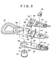
- FIG. 5 shows details of the optical pickup base section.
- the optical pickup base section includes several parts attached to the optical pickup base plate 22.
- a quarter-wave plate 14 and the collimator lens 15 are pasted in an overlapping relationship with each other to a free end portion of the support spring load beam 54.
- the quarter-wave plate 14 has a size of approximately 3 mm wide ⁇ 3 mm long ⁇ 0.1 mm thick.
- the collimator lens 15 has an outer profile of a size of approximately 3 mm wide ⁇ 3 mm long ⁇ 0.3 mm thick, and a lens portion substantially at the center of the collimator lens 15 has a diameter of approximately 0.5 mm.
- the slider suspension section and the collimator lens actuator section are fixed to each other by caulking or welding while an embossed portion 41 provided on the suspension mounting portion 45 is inserted in the hole 42.
- the outer diameter of the embossed portion 41 and the inner diameter of the hole 42 before the caulking or welding provide a mating gap of approximately 10 ⁇ m or less.
- FIGS. 9A to 9D illustrate a method of producing a small-size lens.
- the method uses an existing technique for producing a small-size lens called mold process lens.
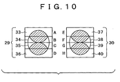
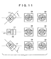
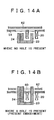
- the optical pickup of the present embodiment is of the swing arm type, when it accesses from an inner circumference to an outer circumference, an azimuth angle appears with respect to the recording track. Variations of the spot shapes on the photo-detectors when an azimuth angle appears can be seen from FIG. 11. If an azimuth angle appears, then the tracking error signal calculated with the expression given above exhibits a decrease of the amplitude W from W0 to W1 as seen from FIGS. 12A and 12B. That the amplitude of the tracking error exhibits a lower value depending upon the place being accessed signifies that the sensitivity of the tracking error signal decreases. Also the S/N (Signal/Noise) ratio of the signal is deteriorated. This signifies that, as the azimuth angle increases, the tracking servo performance deteriorates.
Landscapes
- Physics & Mathematics (AREA)
- Optics & Photonics (AREA)
- Optical Head (AREA)
- Optical Recording Or Reproduction (AREA)
Abstract
Description

Claims (31)
- An optical pickup apparatus comprising:an integrated optical pickup unit (17) for recording or reproducing a signal on or from an optical disk (1),said integrated optical pickup unit including a semiconductor laser for emitting a light beam and an optical system for introducing the light beam; anda swing arm unit (5) for supporting said integrated optical pickup unit (17);said swing arm unit including an optical pickup base plate (22) formed from a thin metal plate having a hole for arrangement of said integrated optical pickup unit (17) formed at an end portion thereof, a semiconductor substrate having said integrated optical pickup unit (17) mounted thereon and mounted on one of faces of said optical pickup base plate (22) to close up said hole of said optical pickup base plate (22), and a transparent cover (16) mounted on the other face of said optical pickup base plate (22) to close up said hole;said integrated optical pickup unit (17) on said semiconductor substrate being disposed in a space formed in said hole of said optical pickup base plate (22) closed up with said semiconductor substrate and said transparent cover (16).
- An optical pickup apparatus according to claim 1, wherein said optical pickup base plate (22) is formed from a thin plate of an iron alloy or a copper alloy.
- An optical pickup apparatus according to claim 1, wherein said transparent cover (16) has a function as an optical part, and said optical pickup base plate (22) has thereon a plated layer whose thickness is controlled so as to adjust the position of said transparent cover (16).
- An optical pickup apparatus according to claim 3, wherein the plated layer on said optical pickup base plate (22) allows sticking of solder thereto.
- An optical pickup apparatus according to claim 4, wherein the plated layer which allows sticking of solder thereto is a plated copper layer or a plated solder layer.
- An optical pickup apparatus according to claim 1, wherein said integrated optical pickup unit (17) is disposed in an inclined relationship by a predetermined inclination angle in a direction from the center of rotation to a tip end of said swing arm unit (5), the predetermined inclination angle being set such that an azimuth angle with respect to recording track substantially at the center of an optical pickup access area of the optical disk is 0 degree or an angle proximate to 0 degree.
- An optical pickup apparatus according to claim 6, further comprising a compensator for compensating for the amplitude of a tracking error signal so as to be fixed irrespective of a variation of the azimuth angle.
- An optical pickup apparatus according to claim 6, further comprising a compensator for compensating for the amplitude of a focusing error signal so as to be fixed irrespective of a variation of the azimuth angle.
- An optical disk apparatus comprising an optical pickup apparatus according to any one of claims 1 to 8 and further comprising:an optical disk driving unit for holding and driving the optical disk to rotate.
- An optical disk apparatus comprising:an optical pickup (8) for illuminating a light beam upon an optical disk (1) to record or reproduce a signal on or from the optical disk (1); anda swing arm unit (5) for supporting said optical pickup (8);said swing arm unit (5) including an optical pickup base plate (22) for holding an integrated optical pickup unit (17) including a semiconductor laser (27) and an optical system, a plate-like support spring (19) disposed in parallel to and along a face of said optical pickup base plate (22) adjacent the optical disk (1), and a suspension (18) disposed in parallel to and along a face of said support spring adjacent the optical disk;said integrated optical pickup unit (17) including a concave lens (53) for increasing the diversion angle of the laser beam emitted from said optical pickup (8);said support spring (19) including a collimator lens (15) for converting the laser beam from the concave lens (53) into parallel light,said suspension (18) including a floating slider (13) in which an objective lens (61) for condensing the laser light from said collimator lens (15) on the optical disk (1) is incorporated.
- An optical disk apparatus according to claim 10, further comprising a collimator lens actuator for driving said support spring (19) to move said collimator lens (15).
- An optical disk apparatus according to claim 11, wherein said collimator lens actuator includes a driving coil (20) and a magnetic circuit (23, 24).
- An optical disk apparatus according to claim 11, wherein said support spring (19) includes a load beam (54) having said collimator lens (15) attached to a tip end portion thereof, said load beam (54) having a stopper (56) projecting higher than the total thickness of optical parts existing between said load beam (54) and said optical pickup base plate (22).
- An optical disk apparatus according to claim 12, wherein said suspension (18) has a hole (60) perforated therein through which said magnetic circuit is to pass.
- An optical disk apparatus according to claim 10, wherein said suspension (18) has a hole formed therein which allows bonding agent to be applied therethrough from the opposite face side to the attaching face of said floating slider (13) to which said floating slider (13) is to be attached when said floating slider (13) is to be fixed to said suspension (18).
- An optical disk apparatus according to claim 10, wherein said suspension (18) includes a flecture for absorbing a movement of said floating slider (13) in roll and pitch directions by means of two twisted hinge portions in two directions disposed symmetrically with respect to the center of said floating slider (13) and has a gap for passing light from said optical pickup (8) therethrough between an adhered portion of said floating slider (13) and said hinge portions.
- An optical disk apparatus according to claim 10, wherein said suspension (18), said support spring (19) and said optical pickup base plate (22) are made of a material of the same type.
- An optical disk apparatus according to claim 17, wherein the material is an iron alloy or a copper alloy.
- An optical disk apparatus according to claim 10, wherein said suspension (18) and said support spring (19) are joined into an assembly part by caulking or welding, and said assembly part is joined to said optical pickup base plate (22) by soldering.
- An optical disk apparatus according to claim 10, wherein said floating slider (13) has a plurality of cutaway portions (46) provided at a mounting portion thereof at which said floating slider (13) is fixed to said suspension (18) and serving as portions to be clamped for adjustment.
- An optical disk apparatus according to claim 10, wherein said integrated optical pickup unit (17) is disposed in an inclined relationship by a predetermined inclination angle in a direction from the center of rotation to a tip end of said swing arm unit (5), the predetermined inclination angle being set such that an azimuth angle with respect to recording track substantially at the center of an optical pickup access area of the optical disk is 0 degree or an angle proximate to 0 degree.
- An optical disk apparatus according to claim 21, further comprising a compensator for compensating for the amplitude of a tracking error signal so as to be fixed irrespective of a variation of the azimuth angle.
- An optical disk apparatus according to claim 21, further comprising a compensator for compensating for the amplitude of a focusing error signal so as to be fixed irrespective of a variation of the azimuth angle.
- An optical disk apparatus comprising:an optical pickup (8) for illuminating a light beam upon an optical disk (1) to record or reproduce a signal on or from the optical disk (1);a moving unit for moving said optical pickup along a signal recording face of the optical disk; anda flexible substrate (25) for supplying a signal to said optical pickup;said flexible substrate (25) having a wiring pattern wherein signal lines necessary for operation of said optical pickup (8) and signal lines necessary only for adjustment of said optical pickup (8) are disposed separately from each other.
- An optical disk apparatus according to claim 24, wherein the signal lines on said flexible substrate (25) which are necessary only for adjustment of said optical pickup (8) are cut after completion of attachment and adjustment of said optical pickup (8).
- An optical disk apparatus according to claim 24, wherein said optical pickup (8) includes a semiconductor substrate on which an integrated optical pickup unit (17) including a semiconductor laser (27) and an optical system is mounted, and a floating slider (13) in which an objective lens (61) is incorporated, and said moving unit includes a swing arm unit (5) which holds said semiconductor substrate and said floating slider (13) thereon.
- An optical disk apparatus according to claim 24, wherein the signal lines, on said flexible substrate (25), which are necessary for operation of said optical pickup (8) include a signal line for transmitting a detection signal of a detector included in said optical pickup (8) for detecting the light beam to a control circuit on an apparatus body side.
- An optical disk apparatus according to claim 24, wherein the signal lines, on said flexible substrate (25), which are necessary for operation of said optical pickup (8) include a signal line for supplying a data signal to be recorded on the optical disk (1) to said optical pickup (8).
- An optical disk apparatus according to claim 24, wherein the signal lines, on said flexible substrate (25), which are necessary for operation of said optical pickup (8) include a signal line for supplying driving power to said optical pickup.
- An optical pickup adjustment method for an optical disk apparatus which includes an optical pickup (8) for illuminating a light beam upon an optical disk (1) to record or reproduce a signal on or from the optical disk (1), a moving unit for moving said optical pickup (8) along a signal recording face of the optical disk (1), and a flexible substrate (25) for supplying a signal to said optical pickup (8), said optical pickup adjustment method comprising the steps of:providing, on said flexible substrate (25), a wiring pattern wherein signal lines necessary for operation of said optical pickup (8) and signal lines necessary only for adjustment of said optical pickup (8) are disposed separately from each other;using the signal lines provided on said flexible substrate (25) and necessary only for adjustment of said optical pickup (8) to transmit signals for adjustment to perform attachment adjustment of said optical pickup (8); andcutting the wiring pattern of the signal lines necessary only for adjustment of said optical pickup (8) after completion of the adjustment of said optical pickup (8).
- An optical pickup adjustment method according to claim 30, wherein at least some of the signal lines of said flexible substrate (25) are connected to external terminals of said optical disk apparatus, and the signals for adjustment include a signal inputted from an external testing apparatus.
Applications Claiming Priority (6)
| Application Number | Priority Date | Filing Date | Title |
|---|---|---|---|
| JP2003312921A JP4239762B2 (en) | 2003-09-04 | 2003-09-04 | Optical pickup device and optical disk device |
| JP2003312397 | 2003-09-04 | ||
| JP2003312397A JP2005085290A (en) | 2003-09-04 | 2003-09-04 | Optical disk device |
| JP2003312921 | 2003-09-04 | ||
| JP2003312655 | 2003-09-04 | ||
| JP2003312655A JP2005085299A (en) | 2003-09-04 | 2003-09-04 | Optical disc apparatus and optical pickup adjusting method thereof |
Publications (2)
| Publication Number | Publication Date |
|---|---|
| EP1513141A2 true EP1513141A2 (en) | 2005-03-09 |
| EP1513141A3 EP1513141A3 (en) | 2008-01-09 |
Family
ID=34139394
Family Applications (1)
| Application Number | Title | Priority Date | Filing Date |
|---|---|---|---|
| EP04292130A Withdrawn EP1513141A3 (en) | 2003-09-04 | 2004-09-03 | Optical pickup apparatus, optical disk apparatus and optical pickup adjustment method |
Country Status (5)
| Country | Link |
|---|---|
| US (1) | US20050094505A1 (en) |
| EP (1) | EP1513141A3 (en) |
| KR (1) | KR20050024219A (en) |
| CN (1) | CN1310231C (en) |
| TW (1) | TW200514065A (en) |
Cited By (1)
| Publication number | Priority date | Publication date | Assignee | Title |
|---|---|---|---|---|
| US20120193504A1 (en) * | 2011-01-28 | 2012-08-02 | Funai Electric Co., Ltd. | Optical Element Holder and Optical Pickup Provided with Same |
Families Citing this family (4)
| Publication number | Priority date | Publication date | Assignee | Title |
|---|---|---|---|---|
| JP4485177B2 (en) * | 2003-12-01 | 2010-06-16 | セイコープレシジョン株式会社 | Shutter device |
| JP4569451B2 (en) * | 2005-11-25 | 2010-10-27 | 株式会社日立製作所 | Optical disk device |
| US7992159B2 (en) * | 2006-03-14 | 2011-08-02 | Panasonic Corporation | Optical pickup device and optical disc device with such optical pickup device mounted thereon |
| US20080268651A1 (en) * | 2006-08-15 | 2008-10-30 | Kent Riley Child | Catch-cup to diverter alignment leveling jig |
Family Cites Families (10)
| Publication number | Priority date | Publication date | Assignee | Title |
|---|---|---|---|---|
| JP2682087B2 (en) * | 1988-11-22 | 1997-11-26 | ソニー株式会社 | Optical pickup device |
| US5828643A (en) * | 1995-06-20 | 1998-10-27 | Sankyo Seiki Mfg. Co., Ltd. | Optical pickup head apparatus |
| US5864448A (en) * | 1995-10-24 | 1999-01-26 | International Business Machines Corporation | Slider and suspension retention and retraction system for high capacity disk drive |
| US6078473A (en) * | 1998-05-13 | 2000-06-20 | Seagate Technology, Inc. | Gimbal flexure for use with microactuator |
| US6970401B2 (en) * | 1999-06-23 | 2005-11-29 | Dphi Acquisitions, Inc. | Fringing field focus motor and mechanism for optical disk drive |
| KR100618992B1 (en) * | 2000-04-03 | 2006-09-04 | 삼성전자주식회사 | Optical recorder |
| US6631113B1 (en) * | 2000-10-04 | 2003-10-07 | Dphi Acquisitions, Inc. | Continuous flexible connection method for miniature optical head |
| JP2002133803A (en) * | 2000-10-31 | 2002-05-10 | Tdk Corp | Very small positioning actuator for head element, head gimbal assembly equipped with the actuator, disk device equipped with the head gimbal assembly, actuator manufacturing method, and head gimbal assembly manufacturing method |
| KR20040111333A (en) * | 2001-11-05 | 2004-12-31 | 시게이트 테크놀로지 엘엘씨 | Load beam attachment to actuator arm |
| KR20030039918A (en) * | 2001-11-16 | 2003-05-22 | 엘지전자 주식회사 | Apparatus optical pick-up of super thin film form |
-
2004
- 2004-09-01 KR KR1020040069471A patent/KR20050024219A/en not_active Withdrawn
- 2004-09-01 US US10/930,808 patent/US20050094505A1/en not_active Abandoned
- 2004-09-03 EP EP04292130A patent/EP1513141A3/en not_active Withdrawn
- 2004-09-03 CN CNB2004100880845A patent/CN1310231C/en not_active Expired - Fee Related
- 2004-09-03 TW TW093126746A patent/TW200514065A/en unknown
Cited By (2)
| Publication number | Priority date | Publication date | Assignee | Title |
|---|---|---|---|---|
| US20120193504A1 (en) * | 2011-01-28 | 2012-08-02 | Funai Electric Co., Ltd. | Optical Element Holder and Optical Pickup Provided with Same |
| US9299383B2 (en) * | 2011-01-28 | 2016-03-29 | Funai Electric Co., Ltd. | Optical element holder and optical pickup provided with same |
Also Published As
| Publication number | Publication date |
|---|---|
| TW200514065A (en) | 2005-04-16 |
| CN1598945A (en) | 2005-03-23 |
| KR20050024219A (en) | 2005-03-10 |
| EP1513141A3 (en) | 2008-01-09 |
| CN1310231C (en) | 2007-04-11 |
| US20050094505A1 (en) | 2005-05-05 |
Similar Documents
| Publication | Publication Date | Title |
|---|---|---|
| US6052357A (en) | Compact optical disk apparatus having a swing-motion optical head | |
| JP5566915B2 (en) | Optical head and optical information device | |
| EP1513141A2 (en) | Optical pickup apparatus, optical disk apparatus and optical pickup adjustment method | |
| EP1522065B1 (en) | Head support mechanism, head drive device, and disk apparatus | |
| JPH09204669A (en) | Optical pickup drive | |
| US20080046901A1 (en) | Recording and reproducing device for optical disk | |
| US20070014205A1 (en) | Objective lens holding device and usage thereof | |
| JP4239762B2 (en) | Optical pickup device and optical disk device | |
| EP1496504A1 (en) | Optical pickup device and optical disk device | |
| US8938746B2 (en) | Object lens driving device and optical disc drive including the same | |
| US6901598B1 (en) | Tilt focus method and mechanism for an optical drive | |
| CN1332382C (en) | Objective lens driving device and optical pickup device using the same | |
| JP2005085299A (en) | Optical disc apparatus and optical pickup adjusting method thereof | |
| JP3379250B2 (en) | Optical head composite and optical recording / reproducing device | |
| JP3570129B2 (en) | Optical pickup module | |
| JP2005085290A (en) | Optical disk device | |
| JP3925505B2 (en) | Optical pickup module | |
| JPH11316963A (en) | Optical pickup | |
| JP2860090B2 (en) | Optical disk drive | |
| JP2004296039A (en) | Optical pickup device | |
| JP2006302338A (en) | Optical pickup and optical disc apparatus | |
| JP2002260367A (en) | Recording / reproducing device and disk cartridge | |
| JP2006179103A (en) | Disk unit | |
| JP2003141765A (en) | Optical pickup device and method of assembling optical pickup device | |
| JP2006031826A (en) | Optical disc apparatus and method for assembling the same |
Legal Events
| Date | Code | Title | Description |
|---|---|---|---|
| PUAI | Public reference made under article 153(3) epc to a published international application that has entered the european phase |
Free format text: ORIGINAL CODE: 0009012 |
|
| AK | Designated contracting states |
Kind code of ref document: A2 Designated state(s): AT BE BG CH CY CZ DE DK EE ES FI FR GB GR HU IE IT LI LU MC NL PL PT RO SE SI SK TR |
|
| AX | Request for extension of the european patent |
Extension state: AL HR LT LV MK |
|
| PUAL | Search report despatched |
Free format text: ORIGINAL CODE: 0009013 |
|
| AK | Designated contracting states |
Kind code of ref document: A3 Designated state(s): AT BE BG CH CY CZ DE DK EE ES FI FR GB GR HU IE IT LI LU MC NL PL PT RO SE SI SK TR |
|
| AX | Request for extension of the european patent |
Extension state: AL HR LT LV MK |
|
| STAA | Information on the status of an ep patent application or granted ep patent |
Free format text: STATUS: THE APPLICATION IS DEEMED TO BE WITHDRAWN |
|
| AKX | Designation fees paid | ||
| 18D | Application deemed to be withdrawn |
Effective date: 20080401 |
|
| REG | Reference to a national code |
Ref country code: DE Ref legal event code: 8566 |