EP1513130A2 - Image display apparatus - Google Patents
Image display apparatus Download PDFInfo
- Publication number
- EP1513130A2 EP1513130A2 EP04015921A EP04015921A EP1513130A2 EP 1513130 A2 EP1513130 A2 EP 1513130A2 EP 04015921 A EP04015921 A EP 04015921A EP 04015921 A EP04015921 A EP 04015921A EP 1513130 A2 EP1513130 A2 EP 1513130A2
- Authority
- EP
- European Patent Office
- Prior art keywords
- discharge
- frequency
- khz
- display apparatus
- image display
- Prior art date
- Legal status (The legal status is an assumption and is not a legal conclusion. Google has not performed a legal analysis and makes no representation as to the accuracy of the status listed.)
- Withdrawn
Links
- 238000010586 diagram Methods 0.000 description 6
- 239000011521 glass Substances 0.000 description 4
- 210000004027 cell Anatomy 0.000 description 3
- 239000000758 substrate Substances 0.000 description 3
- 230000005611 electricity Effects 0.000 description 2
- 238000000034 method Methods 0.000 description 2
- 238000005192 partition Methods 0.000 description 2
- 210000000712 G cell Anatomy 0.000 description 1
- 210000003719 b-lymphocyte Anatomy 0.000 description 1
- 230000000694 effects Effects 0.000 description 1
- 238000009434 installation Methods 0.000 description 1
- 230000002452 interceptive effect Effects 0.000 description 1
- 239000000463 material Substances 0.000 description 1
- 239000011159 matrix material Substances 0.000 description 1
- 230000001681 protective effect Effects 0.000 description 1
Images


Classifications
-
- G—PHYSICS
- G09—EDUCATION; CRYPTOGRAPHY; DISPLAY; ADVERTISING; SEALS
- G09G—ARRANGEMENTS OR CIRCUITS FOR CONTROL OF INDICATING DEVICES USING STATIC MEANS TO PRESENT VARIABLE INFORMATION
- G09G3/00—Control arrangements or circuits, of interest only in connection with visual indicators other than cathode-ray tubes
- G09G3/20—Control arrangements or circuits, of interest only in connection with visual indicators other than cathode-ray tubes for presentation of an assembly of a number of characters, e.g. a page, by composing the assembly by combination of individual elements arranged in a matrix no fixed position being assigned to or needed to be assigned to the individual characters or partial characters
- G09G3/22—Control arrangements or circuits, of interest only in connection with visual indicators other than cathode-ray tubes for presentation of an assembly of a number of characters, e.g. a page, by composing the assembly by combination of individual elements arranged in a matrix no fixed position being assigned to or needed to be assigned to the individual characters or partial characters using controlled light sources
- G09G3/28—Control arrangements or circuits, of interest only in connection with visual indicators other than cathode-ray tubes for presentation of an assembly of a number of characters, e.g. a page, by composing the assembly by combination of individual elements arranged in a matrix no fixed position being assigned to or needed to be assigned to the individual characters or partial characters using controlled light sources using luminous gas-discharge panels, e.g. plasma panels
- G09G3/288—Control arrangements or circuits, of interest only in connection with visual indicators other than cathode-ray tubes for presentation of an assembly of a number of characters, e.g. a page, by composing the assembly by combination of individual elements arranged in a matrix no fixed position being assigned to or needed to be assigned to the individual characters or partial characters using controlled light sources using luminous gas-discharge panels, e.g. plasma panels using AC panels
- G09G3/291—Control arrangements or circuits, of interest only in connection with visual indicators other than cathode-ray tubes for presentation of an assembly of a number of characters, e.g. a page, by composing the assembly by combination of individual elements arranged in a matrix no fixed position being assigned to or needed to be assigned to the individual characters or partial characters using controlled light sources using luminous gas-discharge panels, e.g. plasma panels using AC panels controlling the gas discharge to control a cell condition, e.g. by means of specific pulse shapes
-
- G—PHYSICS
- G09—EDUCATION; CRYPTOGRAPHY; DISPLAY; ADVERTISING; SEALS
- G09G—ARRANGEMENTS OR CIRCUITS FOR CONTROL OF INDICATING DEVICES USING STATIC MEANS TO PRESENT VARIABLE INFORMATION
- G09G2330/00—Aspects of power supply; Aspects of display protection and defect management
- G09G2330/06—Handling electromagnetic interferences [EMI], covering emitted as well as received electromagnetic radiation
Definitions
- This invention relates to an image display apparatus which displays moving images, still images, or character codes (hereinafter, generically called images). More particularly, this invention relates to an image display apparatus using a discharge device, such as a panel display apparatus.
- a panel display apparatus such as a plasma display panel (PDP)
- PDP plasma display panel
- the devices When as high a voltage as about 200V is applied to the discharge devices, the devices discharge. Ultraviolet rays generated from the discharge energy are irradiated to the phosphors. As a result, the pixels emit light, thereby displaying an image.
- the discharge frequency When the PDP is driven, the discharge frequency is constant. The value of the discharge frequency is determined by the manufacturer on the basis of the panel performance, control circuit performance, and so forth.
- the discharge frequency of a PDP is, for example, 207 kHz
- a multiple of 9, higher harmonics lying in the AM radio band (531 kHz to 1062 kHz) are 621, 828, 1035, 1242, and 1449 kHz. All of the frequencies coincide with the AM radio frequencies. That is, when the PDP is driven, broadcasting using a frequency in the frequency range is interfered with.
- the discharge frequency of an existing PDP has been determined on the basis of the required performance (including emission luminance and restrictions on the control circuit). Therefore, when the discharge frequency is set to 207 kHz, all of its higher harmonic frequencies coincide with the AM radio frequencies. In such a situation, it may be that AM radio broadcasting is impossible to listen to. In addition, since the AM radio band has not been included in legal restrictions on EMI, the panel manufacturers are reluctant to take measures. As described above, the existing PDP has the disadvantage of interfering significantly with public broadcasting, such as AM radio.
- Jpn. Pat. Appln. KOKAI Publication No. 10-149136 (a first reference) and in Japan Display '92 "S16-2A Full Color AC Plasma with 256 Gray Scale," pp. 605-608 (a second reference).
- the first reference has disclosed a PDP driving method which alleviates high-frequency interference with the displayed image by changing the frequency of the display clock on an image frame basis.
- the second reference has disclosed a general description of the operation of a PDP.
- an object of the present invention to provide an image display apparatus which reduces interference with public broadcasting, such as AM radio.
- an image display apparatus with discharge devices characterized by comprising a display section (26) which displays an image by causing phosphors to emit light by the discharge energy of the discharge devices; and a discharge frequency control section (24) which controls the discharge frequency of the discharge devices so as to prevent the discharge frequency and its integral-degree harmonic frequencies from coinciding with a public broadcasting frequency in an area where the apparatus is installed.
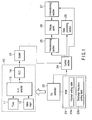
- FIG. 1 is a functional block diagram of a first embodiment of an image display apparatus according to the present invention.
- a video signal output from a signal processing section 10 is supplied to a control section 24 via a scaler 21.
- the signal processing section 10 is controlled by a TV controller 22 on the basis of the data stored in a read-only memory (ROM) 23.
- ROM read-only memory
- the control section 24 acquires various data from the video signal and supplies the data to a data processing section 28.
- the video signal is also supplied to a Y-transforming section 25 and an X-transforming section 27.
- the Y-transforming section 25 and X-transforming section 27 compress and expand the video size according to the display size of a display panel 26.
- the data processing section 28 controls the display panel 26 on the basis of the given data.
- the ROM 23 stores a channel setting table 23a and a discharge frequency setting table 23b into a specific storage area.
- FIG. 2 is a conceptual diagram showing the contents of the channel setting table 23a of FIG. 1.
- the channel setting table 23a relates area codes allocated to a plurality of areas into which the country is divided to the TV broadcasting frequencies in the individual areas.
- the specification is recognized by the TV controller 22.
- the reception frequency of a tuner 11 is set automatically on the basis of the channel setting table 23a.
- This type of function may be called an area setting function.
- FIG. 3 is a conceptual diagram showing the contents of the discharge frequency setting table 23b of FIG. 1.
- the discharge frequency setting table 23b relates the discharge frequencies to be set in the display panel 26 to the individual area codes. When an area code is given, the optimum value of the discharge frequency according to the area is set automatically.
- FIG. 4 is a schematic perspective sectional view showing a structure of the display panel 26 of FIG. 1.
- data electrodes 3 are formed on a glass substrate 1 and display electrodes 4 are formed on a glass substrate 2.
- the data electrodes 3 and display electrodes 4 are formed crosswise in a matrix. Data for display are written into the data electrodes 3.
- the display electrodes 4 are formed in units of two. To isolate discharges taking place at adjacent discharge cells from one another, the data electrodes 3 are partitioned by strip-like partition walls 5.
- Red (R), green (G), and blue (B) phosphors are applied so as to cover the data electrodes and partition walls, with the result that an R cell, a G cell, and a B cell constitute a single pixel.
- the glass substrates 1 and 2 are laminated together with a dielectric layer 7 and a protective film 8 between them and a mixed gas of Ne and Xe is sealed.
- a mixed gas of Ne and Xe is sealed.
- Each of the intersections of the data electrodes 3 and the display electrodes 4 forms a cell.
- the noise frequency can be changed by controlling the discharge frequency of the display electrodes 4.
- the discharge frequency is determined according to the material characteristics of the phosphors 6 of FIG. 4, the length of the address period in the sub-field, and so forth.
- the control section 24 changes the value of the discharge frequency.
- FIG. 5 shows the relationship between the higher harmonic frequencies of the discharge frequency of the display electrode 4 and the AM radio band.
- higher harmonic frequencies lying in the AM radio band are shown with a shaded background.
- FIG. 5 shows the discharge frequencies and their harmonics up to the ninth one.
- FIG. 5 shows that the number of higher harmonic frequencies lying in the AM radio band becomes the smallest in the discharge frequency range of 229 to 265 kHz (four in this case).
- FIG. 5 also shows that the third to sixth harmonic frequencies of the discharge frequency in the range lie in the AM radio band.
- the seventh harmonic (1603 kHz) of a discharge frequency of 229 kHz is only 1 kHz away from the AM radio frequency of 1602 kHz.
- the second harmonic (530 kHz) of a discharge frequency of 265 kHz is only 1 kHz away from the AM radio frequency of 531 kHz.
- the frequency interval between the higher harmonics of the discharge frequency and the AM radio band should be, for example, 5 kHz or higher.
- a discharge frequency which meets the condition and has four higher harmonic frequencies is in the range of 230 to 263 kHz.
- a discharge frequency is expressed as (9 ⁇ m + 1) kHz, where m is an integer.
- Sixth harmonic: 6 ⁇ (9 ⁇ m + 1) (9 ⁇ (6 ⁇ m) + 6) kHz
- any of the third to sixth harmonic frequencies is expressed as a multiple of 9 plus the remainder.
- the third to sixth harmonic frequencies of the discharge frequency are the remainder away from the AM radio frequencies. That is, the third to sixth harmonic frequencies do not coincide with the AM radio frequencies and are almost intermediate between the AM radio frequencies. The more the third to sixth harmonic frequencies are separate from the AM radio frequencies, the more the radio interference is reduced.
- Discharge frequencies which satisfy (9 ⁇ m + 1) or (9 ⁇ m - 1) kHz (where m is an integer) in the range of 229 to 265 kHz are the following eight frequencies: 233, 235, 242, 244, 252, 253, 260, 262 kHz.
- the discharge frequency of the display electrode 4 is tuned to any of those frequencies.
- the discharge frequency itself can be separated sufficiently from the AM radio frequency.
- the integral-degree harmonic frequencies of the discharge frequency can be separated sufficiently from the AM radio frequencies. Therefore, this can eliminate the possibility that reception interference will occur in AM radio.
- the discharge frequency is 261 kHz.
- the ones lying in the AM radio band are the following four frequencies: 783, 1044, 1305, 1566 kHz. All of these frequencies are a multiple of 9 and coincide with the AM radio frequencies.
- the discharge frequency of the display electrode 4 is designed to be changeable to any one of a plurality of switching values.
- two fixed values, 230 kHz and 260 kHz, are considered as the switching values.
- the discharge frequency is switched by the control section 24 according to a command give by the user.
- the number of AM stations receivable in each area is not so large. If the discharge frequency is 230 kHz, the ones of its higher harmonic frequencies lying in the AM radio band are 690, 920, 1150, and 1380 kHz. If the discharge frequency is 260 kHz, the ones of its higher harmonic frequencies lying in the AM radio band are 780, 1040, 1300, and 1560 kHz.
- AM radio interference when the discharge frequency is 230 kHz, AM radio interference has occurred. In this case, when the discharge frequency is switched to 260 kHz, the higher harmonic frequencies shift several tens of kHz. Therefore, AM radio interference can be reduced remarkably.
- the number of selectable discharge frequencies is not limited to two and may be three, four, or more.
- the area codes can be related to the frequency bands of AM public broadcasting for the individual areas. Once the frequency band of AM public broadcasting is found, a discharge frequency capable of minimizing interference can be known beforehand. Therefore, the discharge frequency setting table 23b of FIG. 3 can be prepared beforehand.
- the discharge frequency of the display electrode 4 is set so as to correspond to the input area code. That is, when an area code is input, the discharge frequency corresponding to the code is set on the basis of the contents of the discharge frequency setting table 23b. As a result, the discharge frequency is set automatically by just setting the area code. Therefore, the problems for the user can be eliminated. As described in detail, with the present invention, it is possible to provide an image display apparatus which reduces interference with public broadcasting, such as AM radio broadcasting.
- the present invention is not limited to the above embodiments.
- the invention may be applied to all of the display apparatuses which display images by use of discharge devices.
Landscapes
- Engineering & Computer Science (AREA)
- Physics & Mathematics (AREA)
- Power Engineering (AREA)
- Plasma & Fusion (AREA)
- Computer Hardware Design (AREA)
- General Physics & Mathematics (AREA)
- Theoretical Computer Science (AREA)
- Control Of Indicators Other Than Cathode Ray Tubes (AREA)
- Control Of Gas Discharge Display Tubes (AREA)
- Transforming Electric Information Into Light Information (AREA)
Abstract
An image display apparatus with discharge devices comprises a display section (26) which displays an image by causing phosphors to emit light by the discharge energy of the discharge devices, and a discharge frequency control section (24) which controls the discharge frequency of the discharge devices so as to prevent the discharge frequency and its integral-degree harmonic frequencies from coinciding with a public broadcasting frequency in an area where the apparatus is installed. <IMAGE>
Description
This invention relates to an image display
apparatus which displays moving images, still images,
or character codes (hereinafter, generically called
images). More particularly, this invention relates to
an image display apparatus using a discharge device,
such as a panel display apparatus.
A panel display apparatus, such as a plasma
display panel (PDP), has discharge devices formed
pixel by pixel. When as high a voltage as about 200V
is applied to the discharge devices, the devices
discharge. Ultraviolet rays generated from the
discharge energy are irradiated to the phosphors.
As a result, the pixels emit light, thereby displaying
an image. When the PDP is driven, the discharge
frequency is constant. The value of the discharge
frequency is determined by the manufacturer on the
basis of the panel performance, control circuit
performance, and so forth.
It is well known that noise of a frequency
coinciding with the discharge frequency develops
whenever a discharge device discharges. Since noise
appears even in the higher harmonic part of the
noise-source frequency, this gives rise to noise of
the discharge frequency and its higher harmonic
frequencies.
In Japan, AM radio broadcasting frequencies are
allocated at intervals of 9 kHz in the range of 531 to
1602 kHz. This is expressed by the following equation:
AM radio broadcasting frequencies = (531 + 9 X n) kHz
(n: 0, 1, 2, 3, ..., 118, 119). Since 531 is a multiple
of 9, AM radio frequencies are a multiple of 9.
Not only Japan but also many other countries use such
a frequency allocation.
When the discharge frequency of a PDP is, for
example, 207 kHz, a multiple of 9, higher harmonics
lying in the AM radio band (531 kHz to 1062 kHz)
are 621, 828, 1035, 1242, and 1449 kHz. All of the
frequencies coincide with the AM radio frequencies.
That is, when the PDP is driven, broadcasting using
a frequency in the frequency range is interfered with.
Under the present conditions, measures are taken
to suppress the emission of noise by, for example,
providing an electromagnetic interference (EMI)
glass filter on the image display screen of the PDP.
However, since the discharge voltage is as high as
about 200V, the noise level is very high. When the
screen size is large, the noise generation area is also
large. From these, even if the shield performance is
made higher, this does not lead to an ultimate solution
at present.
The discharge frequency of an existing PDP has
been determined on the basis of the required
performance (including emission luminance and
restrictions on the control circuit). Therefore, when
the discharge frequency is set to 207 kHz, all of its
higher harmonic frequencies coincide with the AM radio
frequencies. In such a situation, it may be that AM
radio broadcasting is impossible to listen to. In
addition, since the AM radio band has not been included
in legal restrictions on EMI, the panel manufacturers
are reluctant to take measures. As described above,
the existing PDP has the disadvantage of interfering
significantly with public broadcasting, such as AM
radio.
Related techniques have been disclosed in Jpn.
Pat. Appln. KOKAI Publication No. 10-149136 (a first
reference) and in Japan Display '92 "S16-2A Full Color
AC Plasma with 256 Gray Scale," pp. 605-608 (a second
reference). The first reference has disclosed a PDP
driving method which alleviates high-frequency
interference with the displayed image by changing
the frequency of the display clock on an image frame
basis. The second reference has disclosed a general
description of the operation of a PDP.
It is, accordingly, an object of the present
invention to provide an image display apparatus which
reduces interference with public broadcasting, such as
AM radio.
According to an aspect of the present invention,
there is provided an image display apparatus with
discharge devices characterized by comprising a display
section (26) which displays an image by causing
phosphors to emit light by the discharge energy of the
discharge devices; and a discharge frequency control
section (24) which controls the discharge frequency of
the discharge devices so as to prevent the discharge
frequency and its integral-degree harmonic frequencies
from coinciding with a public broadcasting frequency in
an area where the apparatus is installed.
Taking such measures enables the discharge
frequencies of the discharge devices to be controlled
so as not to interfere with public broadcasting
frequencies. Therefore, noise can be prevented from
getting mixed in when public broadcasting is received.
This summary of the invention does not necessarily
describe all necessary features so that the invention
may also be a sub-combination of these described
features.
The invention can be more fully understood from
the following detailed description when taken in
conjunction with the accompanying drawings, in which:
Hereinafter, referring to the accompanying
drawings, embodiments of the present invention will
be explained in detail.
FIG. 1 is a functional block diagram of a first
embodiment of an image display apparatus according to
the present invention. In FIG. 1, a video signal
output from a signal processing section 10 is supplied
to a control section 24 via a scaler 21. The signal
processing section 10 is controlled by a TV controller
22 on the basis of the data stored in a read-only
memory (ROM) 23.
The control section 24 acquires various data from
the video signal and supplies the data to a data
processing section 28. The video signal is also
supplied to a Y-transforming section 25 and an X-transforming
section 27. The Y-transforming section 25
and X-transforming section 27 compress and expand the
video size according to the display size of a display
panel 26. The data processing section 28 controls the
display panel 26 on the basis of the given data.
The ROM 23 stores a channel setting table 23a and
a discharge frequency setting table 23b into a specific
storage area.
FIG. 2 is a conceptual diagram showing the
contents of the channel setting table 23a of FIG. 1.
The channel setting table 23a relates area codes
allocated to a plurality of areas into which the
country is divided to the TV broadcasting frequencies
in the individual areas. When the user specifies
an area code by remote control, the specification
is recognized by the TV controller 22. Then, the
reception frequency of a tuner 11 is set automatically
on the basis of the channel setting table 23a.
This type of function may be called an area setting
function.
FIG. 3 is a conceptual diagram showing the
contents of the discharge frequency setting table 23b
of FIG. 1. The discharge frequency setting table 23b
relates the discharge frequencies to be set in the
display panel 26 to the individual area codes. When an
area code is given, the optimum value of the discharge
frequency according to the area is set automatically.
FIG. 4 is a schematic perspective sectional view
showing a structure of the display panel 26 of FIG. 1.
In FIG. 4, data electrodes 3 are formed on a glass
substrate 1 and display electrodes 4 are formed on
a glass substrate 2. The data electrodes 3 and
display electrodes 4 are formed crosswise in a matrix.
Data for display are written into the data electrodes
3. The display electrodes 4, which are so-called
discharge devices, discharge electricity, thereby
causing phosphors to emit light. The display
electrodes 4 are formed in units of two. To isolate
discharges taking place at adjacent discharge cells
from one another, the data electrodes 3 are partitioned
by strip-like partition walls 5.
Red (R), green (G), and blue (B) phosphors are
applied so as to cover the data electrodes and
partition walls, with the result that an R cell, a G
cell, and a B cell constitute a single pixel. Then,
the glass substrates 1 and 2 are laminated together
with a dielectric layer 7 and a protective film 8
between them and a mixed gas of Ne and Xe is sealed.
Each of the intersections of the data electrodes 3 and
the display electrodes 4 forms a cell.
As high a voltage as about 200V is applied to the
display electrodes 4, with the result that the display
electrodes 4 discharge electricity. At this time,
noise is generated. The noise frequency can be changed
by controlling the discharge frequency of the display
electrodes 4. The discharge frequency is determined
according to the material characteristics of the
phosphors 6 of FIG. 4, the length of the address period
in the sub-field, and so forth. In the first
embodiment, the control section 24 changes the value of
the discharge frequency.
FIG. 5 shows the relationship between the higher
harmonic frequencies of the discharge frequency of the
display electrode 4 and the AM radio band. In FIG. 5,
higher harmonic frequencies lying in the AM radio band
are shown with a shaded background. FIG. 5 shows the
discharge frequencies and their harmonics up to the
ninth one.
As shown in FIG. 5, it is seen that the number of
higher harmonic frequencies lying in the AM radio band
becomes the smallest in the discharge frequency range
of 229 to 265 kHz (four in this case). FIG. 5 also
shows that the third to sixth harmonic frequencies of
the discharge frequency in the range lie in the AM
radio band.
In FIG. 5, the seventh harmonic (1603 kHz) of
a discharge frequency of 229 kHz is only 1 kHz away
from the AM radio frequency of 1602 kHz. Similarly,
the second harmonic (530 kHz) of a discharge frequency
of 265 kHz is only 1 kHz away from the AM radio
frequency of 531 kHz. When the interval between
frequencies is only 1 kHz, the effect of noise is
liable to be greater.
In the first embodiment, to overcome this problem,
the following condition is imposed: the frequency
interval between the higher harmonics of the discharge
frequency and the AM radio band should be, for example,
5 kHz or higher. Then, a discharge frequency which
meets the condition and has four higher harmonic
frequencies is in the range of 230 to 263 kHz.
Suppose a discharge frequency is expressed as
(9 × m + 1) kHz, where m is an integer. The third to
sixth harmonic frequencies of the discharge frequency
are expressed as the following equations:
Third harmonic: 3 × (9 × m + 1) = (9 × (3 × m)
+ 3) kHz
Fourth harmonic: 4 × (9 × m + 1) = (9 × (4 × m)
+ 4) kHz
Fifth harmonic: 5 × (9 × m + 1) = (9 × (5 × m)
+ 5) kHz
Sixth harmonic: 6 × (9 × m + 1) = (9 × (6 × m)
+ 6) kHz
As described above, any of the third to sixth
harmonic frequencies is expressed as a multiple of
9 plus the remainder.
Since the AM radio frequencies are a multiple of
9, the third to sixth harmonic frequencies of the
discharge frequency are the remainder away from the
AM radio frequencies. That is, the third to sixth
harmonic frequencies do not coincide with the AM radio
frequencies and are almost intermediate between the
AM radio frequencies. The more the third to sixth
harmonic frequencies are separate from the AM radio
frequencies, the more the radio interference is
reduced.
This holds true when the discharge frequency is
(9 × m - 1) kHz, where m is an integer. Discharge
frequencies which satisfy (9 × m + 1) or (9 × m -
1) kHz (where m is an integer) in the range of 229 to
265 kHz are the following eight frequencies: 233, 235,
242, 244, 252, 253, 260, 262 kHz.
In the first embodiment, the discharge frequency
of the display electrode 4 is tuned to any of those
frequencies. By doing this, the discharge frequency
itself can be separated sufficiently from the AM radio
frequency. Similarly, the integral-degree harmonic
frequencies of the discharge frequency can be separated
sufficiently from the AM radio frequencies. Therefore,
this can eliminate the possibility that reception
interference will occur in AM radio.
Next, a second embodiment of the present invention
will be explained.
Suppose the discharge frequency is 261 kHz.
Of the higher harmonic frequencies of the discharge
frequency, the ones lying in the AM radio band are the
following four frequencies: 783, 1044, 1305, 1566 kHz.
All of these frequencies are a multiple of 9 and
coincide with the AM radio frequencies. However, there
is no AM station which uses the four frequencies in
Japan at present. That is, setting the discharge
frequency to 261 kHz makes it possible to minimize
interference with AM radio in Japan at present.
The same holds true for any other country in the world.
Next, a third embodiment of the present invention
will be explained.
In the third embodiment, the discharge frequency
of the display electrode 4 is designed to be changeable
to any one of a plurality of switching values. In the
third embodiment, two fixed values, 230 kHz and
260 kHz, are considered as the switching values.
The discharge frequency is switched by the control
section 24 according to a command give by the user.
The number of AM stations receivable in each
area is not so large. If the discharge frequency is
230 kHz, the ones of its higher harmonic frequencies
lying in the AM radio band are 690, 920, 1150, and
1380 kHz. If the discharge frequency is 260 kHz,
the ones of its higher harmonic frequencies lying in
the AM radio band are 780, 1040, 1300, and 1560 kHz.
For example, it is assumed that, when the
discharge frequency is 230 kHz, AM radio interference
has occurred. In this case, when the discharge
frequency is switched to 260 kHz, the higher harmonic
frequencies shift several tens of kHz. Therefore,
AM radio interference can be reduced remarkably.
The number of selectable discharge frequencies is not
limited to two and may be three, four, or more.
In recent years, many TV sets with an area setting
function have been provided. Before using a display
device with the area setting function for the first
type, the user inputs to the system an area code
corresponding to the area in which the TV set is
installed. The area code is supplied to the system by
selecting the area corresponding to the installation
location of the device from the menu displayed on the
screen or inputting the postal code for the area.
A remote controller is used for such operation.
The area codes can be related to the frequency
bands of AM public broadcasting for the individual
areas. Once the frequency band of AM public
broadcasting is found, a discharge frequency capable
of minimizing interference can be known beforehand.
Therefore, the discharge frequency setting table 23b of
FIG. 3 can be prepared beforehand.
In the fourth embodiment, the discharge frequency
of the display electrode 4 is set so as to correspond
to the input area code. That is, when an area code
is input, the discharge frequency corresponding to
the code is set on the basis of the contents of the
discharge frequency setting table 23b. As a result,
the discharge frequency is set automatically by just
setting the area code. Therefore, the problems for the
user can be eliminated. As described in detail, with
the present invention, it is possible to provide an
image display apparatus which reduces interference with
public broadcasting, such as AM radio broadcasting.
The present invention is not limited to the above
embodiments. For instance, while each of the above
embodiments has been explained using a PDP as an
example, the invention may be applied to all of the
display apparatuses which display images by use of
discharge devices.
Claims (9)
- An image display apparatus with discharge devices characterized by comprising:a display section (26) which displays an image by causing phosphors to emit light by the discharge energy of the discharge devices; anda discharge frequency control section (24) which controls the discharge frequency of the discharge devices so as to prevent the discharge frequency and its integral-degree harmonic frequencies from coinciding with a public broadcasting frequency in an area where the apparatus is installed.
- The image display apparatus according to claim 1, characterized in that, when there are a plurality of public broadcasting frequencies in the area, the discharge frequency-control section (24) controls the discharge frequency in such a manner that the discharge frequency and its integral-degree harmonic frequencies are located almost in the middle of the intervals between said plurality of public broadcasting frequencies.
- An image display apparatus with discharge devices characterized by comprising:a display section (26) which displays an image by causing phosphors to emit light by the discharge energy of the discharge devices; anda discharge frequency control section (24) which sets the discharge frequency of the discharge devices to either (9n + 1) kHz or (9n - 1) kHz, where n is an integer.
- The image display apparatus according to claim 3, characterized in that the discharge frequency can be switched to any one of a plurality of frequency values, and
the discharge frequency control section (24) selects any one of said plurality of frequency values according to an area where the apparatus is installed. - The image display apparatus according to claim 4, characterized by further comprising a tuner (11) which receives a television broadcast wave transmitted from a broadcasting station in the area and demodulates an image signal to display an image on the image display apparatus, and
a frequency setting section (22) which sets a reception frequency in the tuner according to a specified area code,
wherein the discharge frequency control section (24) selects one frequency value corresponding to the area code from said plurality of frequency values. - An image display apparatus with discharge devices characterized by comprising:a display section (26) which displays an image by causing phosphors to emit light by the discharge energy of the discharge devices; anda discharge frequency control section (24) which sets the discharge frequency of the discharge devices in a range of 229 kHz to 265 kHz.
- The image display apparatus according to claim 6, characterized in that the discharge frequency control section (24) sets the discharge frequency to 261 kHz.
- The image display apparatus according to claim 6, characterized in that the discharge frequency can be switched to any one of a plurality of frequency values, and
the discharge frequency control section (24) selects any one of said plurality of frequency values according to an area where the apparatus is installed. - The image display apparatus according to claim 8, characterized by further comprising a tuner (11) which receives a television broadcast wave transmitted from a broadcasting station in the area and demodulates an image signal to display an image on the image display apparatus, and
a frequency setting section (22) which sets a reception frequency in the tuner according to a specified area code,
wherein the discharge frequency control section (24) selects one frequency value corresponding to the area code from said plurality of frequency values.
Applications Claiming Priority (2)
| Application Number | Priority Date | Filing Date | Title |
|---|---|---|---|
| JP2003195979A JP2005031368A (en) | 2003-07-11 | 2003-07-11 | Image display device |
| JP2003195979 | 2003-07-11 |
Publications (1)
| Publication Number | Publication Date |
|---|---|
| EP1513130A2 true EP1513130A2 (en) | 2005-03-09 |
Family
ID=34074335
Family Applications (1)
| Application Number | Title | Priority Date | Filing Date |
|---|---|---|---|
| EP04015921A Withdrawn EP1513130A2 (en) | 2003-07-11 | 2004-07-06 | Image display apparatus |
Country Status (4)
| Country | Link |
|---|---|
| US (1) | US20050017926A1 (en) |
| EP (1) | EP1513130A2 (en) |
| JP (1) | JP2005031368A (en) |
| CN (1) | CN1577437A (en) |
Families Citing this family (4)
| Publication number | Priority date | Publication date | Assignee | Title |
|---|---|---|---|---|
| KR101342104B1 (en) * | 2007-01-06 | 2013-12-18 | 삼성디스플레이 주식회사 | METHOD FOR IMPROVING ELECTROMAGNETIC INTERFERENCE BY CHANGING DRIVING FREQUENCY ANd LIQUID CRYSTAL DISPLAY USING THEREOF |
| JP2012242194A (en) * | 2011-05-18 | 2012-12-10 | Casio Comput Co Ltd | Radio controlled timepiece |
| CN102637418B (en) * | 2012-04-23 | 2014-07-23 | 天珑移动技术股份有限公司 | Liquid crystal display refreshing method, mobile terminal and control method thereof |
| JP6087244B2 (en) * | 2013-09-04 | 2017-03-01 | アルパイン株式会社 | Position detection device |
Family Cites Families (2)
| Publication number | Priority date | Publication date | Assignee | Title |
|---|---|---|---|---|
| JP2502829B2 (en) * | 1991-03-22 | 1996-05-29 | 松下電器産業株式会社 | Image display device |
| US6850213B2 (en) * | 2001-11-09 | 2005-02-01 | Matsushita Electric Industrial Co., Ltd. | Energy recovery circuit for driving a capacitive load |
-
2003
- 2003-07-11 JP JP2003195979A patent/JP2005031368A/en active Pending
-
2004
- 2004-07-06 EP EP04015921A patent/EP1513130A2/en not_active Withdrawn
- 2004-07-09 US US10/887,302 patent/US20050017926A1/en not_active Abandoned
- 2004-07-09 CN CNA2004100635519A patent/CN1577437A/en active Pending
Also Published As
| Publication number | Publication date |
|---|---|
| US20050017926A1 (en) | 2005-01-27 |
| CN1577437A (en) | 2005-02-09 |
| JP2005031368A (en) | 2005-02-03 |
Similar Documents
| Publication | Publication Date | Title |
|---|---|---|
| US20080155466A1 (en) | Image display device for displaying small-sized image and method thereof | |
| US20050017926A1 (en) | Image display apparatus | |
| JP3645396B2 (en) | Plasma display | |
| KR101076162B1 (en) | Image display device and the method for controlling | |
| KR100733746B1 (en) | Plasma display device and method of reducing interference to radio-broadcasting waves, caused by electromagnetic waves derived from plasma display device | |
| KR100672563B1 (en) | PDTV's power controller | |
| US20070091019A1 (en) | Display apparatus and control method thereof | |
| JP2003202811A (en) | Plasma display | |
| KR100805404B1 (en) | Module Control Device and Method of Image Display Equipment | |
| KR20060094321A (en) | Imager and its resolution optimization method | |
| KR100407972B1 (en) | Apparatus for protecting module of pdp tv | |
| US7215077B2 (en) | Plasma display apparatus and fluorescent material for plasma display panel | |
| US6541914B1 (en) | Plasma display panel including grooves in phosphor | |
| KR100382506B1 (en) | Apparatus for controlling power of PDP TV | |
| KR20110105027A (en) | Image display device and control method | |
| GB2325812A (en) | Video data interfacing apparatus for a flat panel display | |
| KR100492950B1 (en) | Driving system for ac plasma display panel | |
| GB2326512A (en) | Timing control of a plasma display | |
| KR100565494B1 (en) | Structure of plasma display panel | |
| JP2005316050A (en) | Drive unit and driving method for display panel | |
| KR100658852B1 (en) | Plasma display device | |
| KR20050012468A (en) | Method and Apparatus For Driving Plasma Display Panel | |
| KR20060035520A (en) | Plasma display device | |
| KR20060091176A (en) | Video equipment | |
| US4017893A (en) | Display device for producing polychromatic luminous images |
Legal Events
| Date | Code | Title | Description |
|---|---|---|---|
| PUAI | Public reference made under article 153(3) epc to a published international application that has entered the european phase |
Free format text: ORIGINAL CODE: 0009012 |
|
| 17P | Request for examination filed |
Effective date: 20040706 |
|
| AK | Designated contracting states |
Kind code of ref document: A2 Designated state(s): AT BE BG CH CY CZ DE DK EE ES FI FR GB GR HU IE IT LI LU MC NL PL PT RO SE SI SK TR |
|
| AX | Request for extension of the european patent |
Extension state: AL HR LT LV MK |
|
| STAA | Information on the status of an ep patent application or granted ep patent |
Free format text: STATUS: THE APPLICATION HAS BEEN WITHDRAWN |
|
| 18W | Application withdrawn |
Effective date: 20070223 |