EP1513128A2 - Image display apparatus and image display method - Google Patents
Image display apparatus and image display method Download PDFInfo
- Publication number
- EP1513128A2 EP1513128A2 EP04021001A EP04021001A EP1513128A2 EP 1513128 A2 EP1513128 A2 EP 1513128A2 EP 04021001 A EP04021001 A EP 04021001A EP 04021001 A EP04021001 A EP 04021001A EP 1513128 A2 EP1513128 A2 EP 1513128A2
- Authority
- EP
- European Patent Office
- Prior art keywords
- liquid
- image display
- flow path
- image
- segment fluid
- Prior art date
- Legal status (The legal status is an assumption and is not a legal conclusion. Google has not performed a legal analysis and makes no representation as to the accuracy of the status listed.)
- Withdrawn
Links
Images





Classifications
-
- G—PHYSICS
- G09—EDUCATION; CRYPTOGRAPHY; DISPLAY; ADVERTISING; SEALS
- G09F—DISPLAYING; ADVERTISING; SIGNS; LABELS OR NAME-PLATES; SEALS
- G09F13/00—Illuminated signs; Luminous advertising
- G09F13/24—Illuminated signs; Luminous advertising using tubes or the like filled with liquid, e.g. bubbling liquid
Definitions
- the present invention relates to an image display apparatus, in particular, a thin image display apparatus such as a flat panel display and an image display method therefor.
- a liquid crystal display apparatus has been widely used as an image display apparatus of an information terminal device, such as a personal computer or a personal digital assistant (PDA), or a car navigation system.
- the liquid crystal display apparatus has advantages such as a high response speed and an ability to display clear color moving images, although it also has disadvantages such as a complicated structure and a high production cost resulting in a high product price, a high power consumption, necessity of supplying electric power for image holding, a narrow viewing angle, and the like. Therefore, image display apparatuses adopting various systems are proposed as alternatives to the liquid crystal display apparatus.
- a display apparatus which performs switching between ON and OFF of an image by utilizing a liquid film boiling phenomenon (see JP 05-127603 A and JP 05-127604 A, for instance). Also, a display apparatus is proposed which loads/unloads ink in a cell into/from an image display portion through thermal expansion/shrinkage of the ink or mechanical driving of a diaphragm, thereby performing switching between ON and OFF of an image (see JP 2001-42794 A, for instance).
- a display apparatus which adopts a system where approximately one-half of lightproof fluid is sealed in a translucent enclosure (cell) partially covered with a light shielding mask and switching between light transmission and light shielding is performed by driving the lightproof fluid using a gradient of the surface tension of the lightproof fluid caused through irradiation of infrared rays from outside (see JP 2002-169105 A, for instance).
- the duration of the film boiling is as short as 10 ⁇ sec, so there is a problem in that in order to continue to display an image, it is required to continue to apply a voltage of around 10 kHz. Aside from this, there are various problems in that the durability of the apparatus is low and the chromas of displayed images are low and the like.
- the thermal expansion coefficient of the ink is low, so even if the ink is heated to a temperature of from 300 K to 350 K, the volume change of the ink is as small as about 2%. Therefore, in order to ensure a predetermined volume increase, a reservoir tank that is considerably large with respect to the volume of the image display portion is required, which leads to a problem in that the size of the apparatus becomes larger. Also, in the case of the system based on the diaphragm mechanical driving, there is a problem in that the structure of the apparatus becomes complicated, which inhibits miniaturization of the apparatus.
- the present invention has been made in order to solve the problems described above and has an object to provide an image display apparatus and an image display method, with which it becomes possible to hold written information without supply of energy from outside, to form an image that is high in durability and chroma, to realize a simple structure, and to achieve miniaturization.
- the present invention provides an image display apparatus that displays an image using liquid, comprising an image display plate having an image display region, a flow path provided in accordance with the image display region and regulating a moving direction of the fluid and a segment fluid row formation means for generating a segment fluid row, in which plural liquid masses each of which includes first liquid having at least one predetermined coloring matter and are separated from each other are arranged in a row shape, by sequentially and intermittently supplying predetermined amounts of the first liquid to the flow path in accordance with image information of a desired image to be displayed, and causing the generated segment fluid row to move in the flow path, wherein the desired image is displayed in the image display region by the first liquid of the segment fluid row moved to a predetermined position of the flow path.
- the plural liquid masses of the segment fluid row are separated from each other by gas or liquid.
- the segment fluid row formation means generates the segment fluid row by arranging plural liquid masses made of second liquid having transparency in a row shape through division of the second liquid in advance and injecting the first liquid into the plural liquid masses of the second liquid in accordance with the image information.
- the segment fluid row formation means generates the segment fluid row by arranging the plural liquid masses made of the first liquid in a row manner through division of the first liquid in advance and injecting second liquid into the plural liquid masses of the first liquid in accordance with the image information.
- An example of the first liquid included in each liquid mass may be one of liquid colored using at least one of three coloring matters for R (red), G (green), and B (blue) and liquid colored using at least one of four coloring matters for C (cyan), M (magenta), Y (yellow), and K (black).
- the flow path includes a position adjustment means for, when the movement of the segment fluid row by the segment fluid row formation means is stopped, adjusting a position of each liquid mass of the segment fluid row.
- An example of the position adjustment means may be one of water-repellent treatment portions and water-receptive treatment portions formed for a wall surface of the flow path and holding each liquid mass of the segment fluid row.
- position adjustment means may be depression portions formed for a wall surface of the flow path and holding each liquid mass of the segment fluid row.
- the flow path may have one flow path entrance and one flow path exit and one segment fluid row moving path may be formed between the flow path entrance and the flow path exit.
- the flow path may have at least two flow path entrances and at least two flow path exits, with the flow path entrances and the flow path exits being in a one-to-one correspondence, and at least two segment fluid row moving paths may be formed between the flow path entrances and the flow path exits.
- the segment fluid row moving paths extend parallel to each other.
- the present invention also provides an image display method for displaying an image using liquid, comprising generating a segment fluid row, in which plural liquid masses each of which includes first liquid having at least one predetermined coloring matter and are separated from each other are arranged in a row shape, by sequentially and intermittently supplying predetermined amounts of the first liquid in accordance with image information of a desired image to be displayed to a flow path provided in accordance with an image display region for image displaying, and displaying the desired image in the image display region with the first liquid by causing the generated segment fluid row to move to a predetermined position of the flow path.
- an image display apparatus and an image display method with which it becomes possible to hold written information without supply of energy from outside, to form an image that is high in durability and chroma, to realize a simple structure, and to achieve miniaturization.
- FIG. 1 is a plan view of an image display apparatus 10 according to this embodiment.
- FIG. 2A is a vertical cross-sectional view showing a cross section where the image display apparatus 10 is cut along a plane extending along the line A-A' in FIG. 1 and perpendicular to the paper plane of FIG. 1.
- the term "vertical cross-sectional view” means a cross-sectional view taken along a plane extending orthogonal to a paper plane or to an image display plate 1 to be described later.
- FIG. 2B is a vertical cross-sectional view where the image display apparatus 10 is cut along a plane extending along the line B-B' in FIG. 1.
- the image display apparatus 10 includes a flat-plate-shaped image display plate 1 and a segment fluid row formation unit (segment fluid row formation means) 3 arranged adjacent to the image display plate 1.
- the image display plate 1 is made of a transparent material, meaning that the material of the image display plate 1 is not specifically limited. For instance, it is possible to use glass, acrylic, a transparent resin, such as vinyl chloride, or the like as the material of the image display plate 1.
- the segment fluid row formation unit 3 forms a segment fluid row where liquid masses that have predetermined coloring matters and are separated from each other by fluid are arranged in a row shape.
- the liquid masses will be referred to as the “liquid D” (see FIG. 13) and the fluid separating the liquid D will be referred to as the “separation fluid V" (see FIG. 13).
- a hollow flow path 2 is formed in the image display plate 1. Also, multiple pixel equivalent portions are arranged in a matrix shape on the upper surface of the image display plate 1, thereby forming an image display region.
- the flow path 2 is formed below the pixel equivalent portions in the image display region in a zigzag shape where the flow path 2 traces every pixel equivalent portion with so-called "one stroke". Aside from this, the flow path 2 may also be formed in a spiral shape, for instance.
- the flow path 2 is formed by a single tubular hole formed in a zigzag shape in the image display plate 1. That is, as shown in FIG. 1, the flow path 2 is formed by repeating a pattern where the flow path extends from one end to the other end in a widthwise direction of the image display plate 1, is bent by 180° at the other end, and extends back to the one end. With this construction, the flow path 2 functions as a moving path, where the first liquid flows, that regulates the moving direction of fluid.
- the flow path 2 in the image display apparatus 10 has a rectangular cross section, although the cross-sectional shape is not limited to this. That is, the flow path 2 may be formed so as to have a non-rectangular cross section, such as a circular cross section, an oval cross section, or a closed-curve cross section. Also, as shown in FIG. 1, in the image display apparatus 10 according to this embodiment, the flow path 2 is formed in a shape that is bent at right angles in the vicinity of the right and left end portions of the image display plate 1, although the present invention is not limited to this.
- a part of the flow path 2 may be formed in a shape where each portion connecting the end portions of two adjacent straight-line portions is formed in a curved shape so as to have a horizontal cross section (cross section cut along a plane extending parallel to the upper surface of the display plate) drawing a circular arc.
- the shape and area of the cross section of the flow path 2 are not specifically limited irrespective of the surface tensions of the separation fluid and the first liquid to be described later so long as smooth flow is possible.
- the size (width, height, or diameter) of the cross section of the flow path 2 may be set at 0.2 to 5 mm ⁇ 0.2 to 5 mm and the cross-sectional area of the flow path 2 may be set at 0.04 ⁇ 25 mm 2 .
- multiple flow paths 2 may be formed in the single image display plate 1.
- multiple flow paths 2 may be formed parallel to each other and parallel to a vertex portion 11 or side portions 13 of the image display plate 1.
- the flow path 2 may be a tube made of a transparent material.
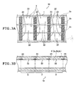
- FIG. 3A is a partially enlarged plan view of the image display plate 1 and FIG. 3B is a partially enlarged cross-sectional view of the image display plate 1.
- the two-dot chain lines indicate boundaries between pixel equivalent portions X, each of which corresponds to one pixel.
- ink-repellent treatment portions 23 are provided in the upper portion of the flow path wall surface of the flow path 2 (2a, 2b, 2c) and the pixel equivalent portions X (X 1 , X 2 , X 3 , ... , X n ), each of which corresponds to one pixel are obtained through division by the ink-repellent treatment portions 23.
- each "ink-repellent treatment portion” refers to a portion on which ink-repellent treatment is implemented and the property is given for repelling liquid D to be described later.
- water-repellent treatment corresponds to the "ink-repellent treatment”.
- oil-based ink is used, water-receptive treatment corresponds to the "ink-repellent treatment”.
- water-repellent treatment portions that are one kind of the ink-repellent treatment portions
- a method for forming water-repellent treatment portions it is possible to use a method with which a fluorine-based material, such as fluororesin, is patterned through lithography processing following the application of the fluorine-based material, a method with which a silicon-based material is applied, a method with which surface roughness is changed, or the like.
- the ink-repellent treatment portions 23 are formed on the periphery of the boundary portions between the pixel equivalent portions in the flow path 2, so that the upper portion of the wall surface of the flow path 2 between two adjacent ink-repellent treatment portions 23 becomes the position adjustment portions 22 having a relative affinity for the ink constituting the liquid D. Therefore, even when the liquid D that should be held at the position of a position adjustment portion 22 halts at a position between two adjacent position adjustment portions 22, where the ink-repellent treatment portion 23 is formed, so the liquid D is caused to move to the position of the position adjustment portion 22 having a higher affinity.
- a "self-alignment effect” is obtained which is an effect that it is possible to adjust the position of the liquid D supplied into the flow path 2 by means of the property of the flow path 2 itself.
- the ink-repellent treatment portions 23 may be formed only in a part of the image display plate 1.
- segment fluid row formation unit 3 As shown in FIG. 1, the segment fluid row formation unit (segment fluid row formation means) 3 is disposed in the left-side upper portion of the image display apparatus 10 in FIG. 1. This segment fluid row formation unit 3 generates a segment fluid row by alternately supplying the liquid D and the separation fluid V into the flow path 2 and causes the generated segment fluid row to move in the flow path 2, thereby displaying an image on the image display plate 1.
- FIG. 4 a schematic diagram showing an internal construction of the segment fluid row formation unit 3 according to this embodiment.
- vessels 41a, 41b, and 41c each of which contains the first liquid
- pumps 43a, 43b, and 43C each of which respectively supplies the first liquid contained in the vessels 41a, 41b, and 41c
- vessels 45a, 45b, and 45c each of which contains second liquid
- pumps 46a, 46b, and 46c each of which respectively supplies the second liquid contained in the vessels 45a, 45b, and 45c
- a pump 50 that supplies the separation fluid V
- the pumps 43a, 43b, 43c, 46a, 46b, and 46c may be diaphragm pumps.
- actuators that drive diaphragm portions of the diaphragm pumps may be electrostatic force actuators, piezo actuators, thermal bimorph actuators, thermal-pressure effect (thermo-pneumatic) actuators, or the like.
- the "first liquid" contained in each vessel 41a, 41b, or 41c is ink having a coloring matter and is not specifically limited so long as it is liquid that is capable of moving in the flow path 2 and displaying a specific color in the flow path 2.
- the first liquid in each vessel 41a, 41b, or 41c may be liquid where a pigment or a dye is mixed with colorless and transparent liquid, such as ink having a coloring matter for one of R (red), G (green), and B (blue) or for one of Y (yellow), M (magenta), C (cyan), and K (black) and exhibiting a specific color or liquid where such ink is diluted with a diluent.
- Y (yellow) ink, M (magenta) ink, and C (cyan) ink are used as the first liquid, with the Y (yellow) ink contained in the vessel 41a, the M (magenta) ink contained in the vessel 41b, and the C (cyan) ink contained in the vessel 41c.
- the "second liquid” refers to liquid having compatibility with the first liquid described above.
- the second liquid is mixed with the first liquid and constitutes the liquid D having a desired optical density (hereinafter simply referred to as the "density").
- the second liquid may be omitted.
- the second liquid is not specifically limited so long as it is colorless and transparent liquid having compatibility with the first liquid. For instance, it is possible to use water, each kind of hydrocarbon, silicon oil, or the like as the second liquid.
- carrier liquid S is used as the second liquid and is contained in the vessels 45a, 45b, and 45c.
- the separation fluid V is fluid that is inserted between two of liquid D existing adjacent to each other through the separation fluid V in front and back of the moving direction of fluid in the flow path 2, and maintains a constant distance therebetween.
- the separation fluid V is not specifically limited so long as it is fluid that has no compatibility with the liquid D and provides such a constant distance maintaining effect.
- the separation fluid V may be gas or liquid.
- As the separation fluid V that is liquid, water, each kind of hydrocarbon, silicon oil, and the like may be used for example.
- the separation fluid V that is gas air, nitrogen gas, an inert gas, and the like may be used for example. In this embodiment, air is used as the separation fluid V.
- the pump 50 and the flow path 2 are connected to each other through a pipe 37 and three pipes 36a, 36b, and 36c that branch in three directions from the pipe 37.
- the pipes 36a, 36b, and 36c merge with each other at a merge point 21 provided in an end portion of the flow path 2 on an upstream side in the fluid moving direction (at the upper left corner in FIG. 1).
- the pipe 36a is connected to the vessel 45a and the pump 46a through a connection portion 362a and, when the pump 46a is actuated, the carrier liquid S contained in the vessel 45a is supplied to the connection portion 362a of the pipe 36a.
- the pipe 36a is connected to the vessel 41a and the pump 43a through a connection portion 361a and, when the pump 43a is actuated, the Y (yellow) ink contained in the vessel 41a is supplied to the connection portion 361a of the pipe 36a.
- the pipe 36a is provided with a valve 35a and supply of the separation fluid V to the pipe 36a is controlled through opening/closing of the valve 35a.
- the pipe 36b is connected to the vessel 45b and the pump 46b through a connection portion 362b and, when the pump 46b is actuated, the carrier liquid S contained in the vessel 45b is supplied to the connection portion 362b of the pipe 36b.
- the pipe 36b is connected to the vessel 41b and the pump 43b through a connection portion 361b and, when the pump 43b is actuated, the M (magenta) ink contained in the vessel 41b is supplied to the connection portion 361b of the pipe 36b.
- the pipe 36b is provided with a valve 35b and supply of the separation fluid V to the pipe 36b is controlled through opening/closing of the valve 35b.
- the pipe 36c is connected to the vessel 45c and the pump 46c through a connection portion 362c and, when the pump 46c is actuated, the carrier liquid S contained in the vessel 45c is supplied to the connection portion 362c of the pipe 36c.
- the pipe 36c is connected to the vessel 41c and the pump 43c through a connection portion 361c and, when the pump 43c is actuated, the C (cyan) ink contained in the vessel 41c is supplied to the connection portion 361c of the pipe 36c.
- the pipe 36c is provided with a valve 35c and supply of the separation fluid V to the pipe 36c is controlled through opening/closing of the valve 35c.
- the pump 43a and the control portion 30 are connected to each other through wiring 33a, the pump 46a and the control portion 30 are connected to each other through wiring 34a, and the valve 35a and the control portion 30 are connected to each other through wiring 32a.
- the pump 43b and the control portion 30 are connected to each other through wiring 33b, the pump 46b and the control portion 30 are connected to each other through wiring 34b, and the valve 35b and the control portion 30 are connected to each other through wiring 32b.
- the pump 43c and the control portion 30 are connected to each other through wiring 33c, the pump 46c and the control portion 30 are connected to each other through wiring 34c, and the valve 35c and the control portion 30 are connected to each other through wiring 32c.
- start and stop of supply of the carrier liquid S, the Y (yellow) ink, and the separation fluid V into the pipe 36a are controlled through actuation of the pumps 43a and 46a and the valve 35a under control by the control portion 30.
- start and stop of supply of the carrier liquid S, the M (magenta) ink, and the separation fluid V into the pipe 36b are controlled through actuation of the pumps 43b and 46b and the valve 35b under control by the control portion 30.
- start and stop of supply of the carrier liquid S, the C (cyan) ink, and the separation fluid V into the pipe 36c are controlled through actuation of the pumps 43c and 46c and the valve 35c under control by the control portion 30. Consequently, switching between start and stop of supply of the liquid D is performed through control of the actuation of the pumps 43a to 43c and the pumps 46a to 46c and the opening/closing of the valves 35a to 35c.
- liquid D having a specific color in the image display apparatus of this embodiment
- multiple kinds of the first liquid composing liquid D are formed in the pipes 36 (36a, 36b, 36c) and are merged at the merge point 21 and mixed with each other, thereby forming liquid D exhibiting a desired color.
- the pump 46a is actuated and a predetermined amount of carrier liquid S 1 is supplied to the connection portion 362a of the pipe 36a. Then, the pump 46a is stopped and the valve 35a is opened for an extremely short period of time, thereby sending the carrier liquid S 1 to the connection portion 361a.
- first liquid Y 1 in Y (yellow) having a predetermined color density is formed at the position of the connection portion 361a.
- the pumps 46b and 43b and the value 35b for M (magenta) and the pumps 46c and 43c and the valve 35c for C (cyan) are actuated in a like manner, thereby forming first liquid M 1 in M (magenta) having a predetermined color density at the position of the connection portion 361b and forming first liquid C 1 in C (cyan) having a predetermined color density at the position of the connection portion 361c.
- the valves 35a to 35c are opened and a predetermined amount of separation fluid V is supplied to the pipes 36a to 36c.
- the first liquid Y 1 , the first liquid M 1 , and the first liquid C 1 move in the pipes 36a to 36c, respectively, by means of the pressure of the separation fluid V and are merged at the merge point 21 and unified with each other.
- the first liquid Y 1 , the first liquid M 1 , and the first liquid C 1 are mixed with each other and liquid D having a predetermined color and a predetermined density is formed. Then, this liquid D is moved and supplied to the flow path 2 by means of the pressure of the separation fluid V.
- the ink may be directly supplied to the connection portions 361a to 361c of the pipes 36a to 36c and sent to the merge point 21 by means of the pressure of the separation fluid V. Also, in accordance with the color to be displayed with the liquid D, the amount of the carrier liquid S supplied to the connection portions 362a to 362c and the amount and kind of the ink injected into the carrier liquid S are adjusted as appropriate.
- the pumps 46 (46a, 46b, 46c) and the vessels 45 (45a, 45b, 45c) for supplying the carrier liquid S are provided on an upstream side in the fluid moving direction of the pipes 36 (36a, 36b, 36c), while the pumps 43 (43a, 43b, 43c) and the vessels 41 (41a, 41b, 41c) for supplying the ink are provided on a downstream side in the fluid moving direction, and the ink is injected into the carrier liquid S supplied to the pipes 36 (36a, 36b, 36c).
- the present invention is not limited to this and another construction may be adopted in which, for instance, the pumps 43 (43a, 43b, 43c) and the vessels 41 (41a, 41b, 41c) for supplying the ink are provided on the upstream side in the fluid moving direction of the pipes 36 (36a, 36b, 36c), while the pumps 46 (46a, 46b, 46c) and the vessels 45 (45a, 45b, 45c) for supplying the carrier liquid S are provided on the downstream side in the fluid moving direction, and the carrier liquid S is injected into the ink supplied to the pipes 36 (36a, 36b, 36c).
- FIG. 5 shows a relation between an input screen 16 and the image display plate 1 in the case where the image display apparatus 10 according to this embodiment is connected to an input apparatus provided with the input screen 16. As shown in FIG. 5, an image display region 15 is formed on the upper surface of the image display plate 1.
- the position adjustment portions are provided in the flow path 2 so that when supply of the liquid D and the separation fluid V is stopped, the liquid D is adjusted so as to be positioned at predetermined positions, and multiple pixel equivalent portions X 1 , X 2 , X 3 , ... are formed in the image display region 15 in a matrix shape in accordance with the positions of the position adjustment portions.
- Each of the pixel equivalent portions X 1 , X 2 , X 3 , ... becomes a pixel for displaying an image in the image display region 15, that is, the minimum unit constituting the image.
- a point p on an image obtained with the input apparatus corresponds to a point P in the image display region 15 indicated on the upper surface of the image display plate 1 with a dotted line. Consequently, when image information at the point p is inputted, the color and density of liquid D that should be positioned at the point P of the image display region 15 are determined.
- FIG. 6 is a flowchart showing a processing flow from the image information input to the actual image formation.
- the control portion 30 sequentially determines a fluid row composed of liquid D and separation fluid V separating the liquid D as a segment fluid row that is necessary to form a point image (dot) at each required point on the image display plate 1 corresponding to one pixel (point P corresponding to the pixel point p in the case shown in FIG. 5).
- the segment fluid row is such a row that when this fluid row is moved in the flow path 2, the liquid D is supplied to predetermined positions of the flow path 2 (more specifically, the positions of dots constituting an image that should be displayed in the image display region 15).
- a segment fluid row is determined in which a certain amount of separation fluid V that fills the flow path 2 from the start portion, that is, the pixel equivalent portion X z at the lower right corner of the image display region 15 to the pixel equivalent portion (X n+1 ) immediately preceding the point P, a certain amount of liquid D filling the flow path 2 in the pixel equivalent portion X n corresponding to the point image (dot) formation point P, and a certain amount of separation fluid V filling the flow path 2 from the pixel equivalent portion (X n-1 ) immediately succeeding the point P to the end portion, that is, the pixel equivalent portion X 1 are arranged in this order.
- the calculated fluid data shows the required amount (w) of liquid D to form the point image (dot) at the point P, the required amounts (volumes) of Y (yellow) ink, M (magenta) ink, and C (cyan) ink to display a color of the point image (dot) at the point P, the required amount (volume) of carrier liquid S, the required volume of separation fluid V to move the liquid D to the position of the point P (that is, the amount of separation fluid V filling the flow path 2 from the pixel equivalent portion X z to the pixel equivalent portion X n+1 and the amount of separation fluid V filling the flow path 2 from the pixel equivalent portion X n-1 to the pixel equivalent portion X 1 ), and the like (step 2).
- timing data data showing actuation timings of the apparatus, such as the actuation timings of the pumps 43a to 43c and the pumps 46a to 46c and the opening/closing timings of the valves 35a to 35c.
- the timing data is calculated (step 3).
- the pumps 43a to 43c, the pumps 46a to 46c, and the valves 35a to 35c are actuated (step 4), thereby supplying the required amounts of Y (yellow) ink, M (magenta) ink, and C (cyan) ink, the required amount of carrier liquid S, and the required amount of separation fluid V into the flow path 2.
- the required amounts of Y (yellow) ink, M (magenta) ink, and C (cyan) ink to form the point image (dot) at the point P are supplied to the pipes 36 (36a, 36b, 36c) (the carrier liquid S is also supplied as necessary). Then, the first liquid supplied into the pipe 36a, the first liquid supplied into the pipe 36b, and the first liquid supplied into the pipe 36c are merged at the merge point 21 and mixed with each other, thereby forming liquid D having a predetermined color and a predetermined density.
- valves 35 are opened/closed at predetermined timings, thereby supplying the liquid D into the flow path 2.
- the valves 35 (35a, 35b, 35c) are opened for a predetermined period of time, thereby supplying a predetermined amount of separation fluid V into the flow path 2.
- FIG. 7 shows a relation between an image to be displayed and the image display region 15 in this case.
- the control portion 30 determines a segment fluid row required to display the letter "A".
- This segment fluid row is such a row that is formed by alternately arranging the liquid D (D 1 , D 2 , D 3 , ..., D z ) for forming point images (dots) at multiple points P 1 , P 2 , P 3 , ..., P z that are display points of an image of the letter "A" in the image display region 15 and the separation fluid V for separating the liquid D (D 1 , D 2 , D 3 , ..., D z ) from each other and supplying the liquid D (D 1 , D 2 , D 3 , ..., D z ) to predetermined positions in the flow path 2 corresponding to the points P 1 , P 2 , P 3 , ..., P z .
- a segment fluid row is determined in which a certain amount of separation fluid V 1 filling the flow path 2 from the pixel equivalent portion X z at the lower right corner of the image display region 15 in FIG. 7 to the point P 1 , liquid D 1 forming a point image (dot) at the point P 1 , a certain amount of separation fluid V 2 filling the flow path 2 between the point P 1 and a point P 2 , liquid D 2 forming a point image (dot) at the point P 2 , a certain amount of separation fluid V 3 filling the flow path 2 between the point P 2 and a point P 3 , liquid D 3 forming a point image (dot) at the point P 3 , a certain amount of separation fluid V 4 filling the flow path 2 between the point P 3 and a point P 4 , ..., liquid D z forming a point image (dot) at a point P z , and a certain amount of separation fluid V z+1 filling the flow path 2 between the point P 1
- fluid data is calculated which gives the required volumes of Y (yellow) ink, M (magenta) ink, C (cyan) ink, and carrier liquid S to obtain the liquid D (D 1 , D 2 , D 3 , ..., D z ) forming the point images (dots) at the points P 1 , P 2 , P 3 , ..., P z , the required volumes of separation fluid V 1 , V 2 , V 3 , ..., V z to move the liquid D (D 1 , D 2 , D 3 , ..., D z ) to the positions of the points P 1 , P 2 , P 3 , ..., P z , and the like.
- timing data is calculated which gives the drive timings of the pumps 46a to 46c and the pumps 43a to 43c and the opening/closing timings of the valves 35a to 35c. Then, based on the calculated timing data, the pumps 46a to 46c and the pumps 43a to 43c are driven and the valves 35a to 35c are opened/closed, thereby supplying the liquid D (D 1 , D 2 , D 3 , ... , D z ) having predetermined volumes and the separation fluid V 1 , V 2 , V 3 , ..., V z into the flow path 2.
- FIG. 8 is a timing chart showing operations from a start to completion of the image formation
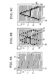
- FIGs. 9A to 9C are plan views showing how a display state in the image display region 15 of the image display apparatus 10 changes by the image formation.
- the valves 35 (35a to 35c) are opened in a time slot of t 0 to t 1,1 , thereby supplying the separation fluid V into the pipes 36 (36a to 36c).
- the pumps 46 (46a to 46c) are actuated in a time slot of t 1,1 to t 1,2 , thereby supplying carrier liquid S corresponding to the liquid D 1 into the pipes 36 (36a to 36c).
- the Y (yellow) ink is injected into the carrier liquid S and Y (yellow) first liquid having a predetermined density is formed in the ink connection portion 361a of the pipe 36a at the time t 1,4 .
- M (magenta) first liquid and C (cyan) first liquid are respectively formed in the ink connection portions 361b and 361c of the pipes 36b and 36c at the time t 1,4 .
- the valves 35a to 35c are opened, thereby supplying a predetermined amount (V 2 ) of separation fluid V into the pipes 36a to 36c.
- the Y (yellow) first liquid, the M (magenta) first liquid, and the C (cyan) first liquid are merged at the merge point 21 and unified with each other and the Y (yellow) ink, the M (magenta) ink, and the C (cyan) ink are mixed with each other.
- the liquid D 1 exhibiting a predetermined color is formed and is supplied to the flow path 2.
- the opening/closing state and the opening/closing time period of each valve of the pumps 43a to 43c may be changed in accordance with the color and density that should be displayed.
- the pumps 46a to 46c are actuated in a time slot of t 2,1 to t 2,2
- the valves 35a to 35c are opened in a time slot of t 2,2 to t 2,3
- the pumps 43a to 43c are actuated in a time slot of t 2,3 to t 2,4
- the valves 35a to 35c are opened in a time slot of t 2,4 to t 3,1 , thereby supplying the liquid D 2 and the separation fluid V 3 into the flow path 2.
- the pumps 46a to 46c are actuated in a time slot t 3,1 to t 3,2
- the valves 35a to 35c are opened in a time slot of t 3,2 to t 3,3
- the pumps 43a to 43c are actuated in a time slot of t 3,3 to t 3,4
- the valves 35a to 35c are opened in a time slot of t 3,4 to t 4,1 , thereby supplying the liquid D 3 and the separation fluid V 4 into the flow path 2.
- the pumps 43a to 43c, the pumps 46a to 46c, and the valves 35a to 35c are actuated at predetermined timings, thereby supplying the liquid D 4 , the separation fluid V 5 , ..., the liquid D n , the separation fluid V n+1 , ... in this order. Then, finally, the liquid D z and the separation fluid V z+1 are supplied in this order. With the passage of time, as shown in FIGs. 9A and 9B, the liquid D (D 1 , D 2 , D 3 , ...
- the separation fluid V (V 1 , V 2 , V 3 , ..., V z+1 ) and the liquid D (D 1 , D 2 , D 3 , ..., D z ) are arranged so that the liquid D (D 1 , D 2 , D 3 , ..., D z ) having predetermined volumes are supplied to the positions of the point images (dots) for displaying the alphabet letter "A" in the image display region 15, that is, the points P 1 , P 2 , P 3 , ..., P z . Therefore, when the segment fluid row determined in the manner described above is formed in the flow path 2, as shown in FIG. 9C, the letter "A" appears in the image display region 15 of the surface of the image display plate 1.
- an image is formed and held through adjustment of the amounts (volumes) of the liquid D and the separation fluid V supplied into the flow path 2.
- an image display apparatus that hold an image without supply of energy from the outside of the apparatus.
- no energy is required for the image holding, so that it becomes possible to provide an image display apparatus that forms an image having high durability.
- the image display plate 1 only the flow path 2 is formed without any minute components such as electrodes and circuits provided. As a result, it becomes possible to provide an image display apparatus that has a simple structure and is capable of achieving miniaturization.
- the control portion 30 identifies its corresponding point P on the image display region 15 and calculates fluid data concerning the volume of liquid D forming an image (dot) at the point P, each ink (Y (yellow), M (magenta), C (cyan)) and carrier liquid S required to construct the liquid D, and separation fluid V required to send the liquid D to the position of the point P, as well as timing data.
- a relation between image information to be inputted (letter "A", for instance) and timing data required to display an image (image of "A", for instance) on the display plate 1 of the image display apparatus 10 may be created as a look-up table in advance and this look-up table may be stored in a storage portion or the like of the control portion 30.
- the timing data and the like required to output the image on the image display apparatus 10 may be obtained from the look-up table.
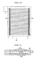
- FIG. 10 is a plan view of an image display apparatus 10c according to the second embodiment of the present invention.
- ink-receptive treatment portions 23a serving as the position adjustment means are provided only for the upper portion of the wall surface of the flow path 2 on the periphery of the right and left end portions of an image display plate 1c and ink-repellent treatment portions are provided for the remaining portions of the wall surface of the flow path 2.
- each "ink-receptive treatment portion” refers to a portion given an affinity for the liquid D.
- a water-receptive treatment portion subjected to water-receptive treatment corresponds to the "ink-receptive treatment portion”.
- oil-based ink is used, a water-repellent treatment portion subjected to water repellent treatment corresponds to the "ink-receptive treatment portion”.
- the ink-receptive treatment portions 23a are provided in the manner described above, so that a self-alignment effect is obtained.
- the ink-receptive treatment portions 23a are only partially provided for the flow path 2 on the periphery of the right and left end portions of the image display plate 1c, so that it becomes possible to reduce the number of steps for forming the ink-receptive treatment portions 23a serving as the position adjustment means.
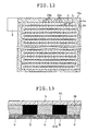
- FIG. 11 is a vertical cross-sectional view where an image display plate 1d of an image display apparatus 10d according to this embodiment is cut along a plane extending along a flow path 230, parallel to the flow path 230, and orthogonal to the surface of the image display plate 1d.
- the width of the flow path 230 in the thickness direction of the image display plate 1d top-bottom direction in FIG.
- this ratio between h 1 and h 2 is determined with reference to the physical properties of ink constituting liquid D, the physical properties of the flow path surface of the flow path 230, the dimensions (length and the like) of the flow path, the output of each pump for pressurizing the ink, and the like.
- the flow path 230 is formed so that its width is increased in each position adjustment portion 230a and is decreased in each passage portion 230b, so that liquid D is easy to be held in the position adjustment portion 230a. Therefore, when a liquid mass D that should be held at the position of a position adjustment portion 230a halts at the position of a passage portion 230b, the liquid D moves to the position of the position adjustment portion 230a where the width of the flow path is set wider and the liquid D is easier to be held. As a result, a "self-alignment effect" is obtained that adjusts the position of the liquid D supplied into the flow path 230.
- ink-repellent treatment portions are formed on the flow path wall surface of the flow path 230. Also, it is more preferable that an ink-repellent treatment portion is formed on the wall surface in each passage portion 230b and an ink-receptive treatment portion is formed on the wall surface in each position adjustment portion 230a.
- FIG. 12 is a horizontal cross-sectional view where an image display plate 1e of an image display apparatus 10e according to this embodiment is cut along a plane extending parallel to the upper surface of the image display plate 1e.
- a flow path 24 is formed so that its width in the plane direction of the image display plate 1e (top-bottom direction in the drawing) is increased in each position adjustment portion 24a corresponding to one pixel, and its width is reduced in each passage portion 24b. That is, as shown in FIG.
- the flow path 24 in the image display plate 1e is formed so that its width in the plane direction is increased in each position adjustment portion 24a and is decreased in each passage portion 24b, so that liquid D becomes easy to be held by the position adjustment portion 24a. Therefore, when a liquid mass D that should be held at the position of a position adjustment portion 24a halts at the position of a passage portion 24b, the liquid D moves to the position of the position adjustment portion 24a where the width of the flow path is set wider and therefore the liquid D is easier to be held. In this manner, a "self-alignment effect" is obtained that adjusts the position of the liquid D supplied into the flow path 24.
- ink-repellent treatment portions are formed on the flow path wall surface of the flow path 24. Also, it is more preferable that an ink-repellent treatment portion is formed on the wall surface in each passage portion 24b and an ink-receptive treatment portion is formed on the wall surface in each position adjustment portion 24a.
- An image display apparatus 10i according to this embodiment has the same structure as the image display apparatus 10 according to the first embodiment except that a reflection plate 210 for reflecting light is provided below a flow path 28 of an image display plate 1i.
- FIG. 13 is a vertical cross-sectional view where an image display plate 1i of the image display apparatus 10i according to this embodiment is cut along a lengthwise direction of the flow path 28. As shown in FIG. 13, in the image display apparatus 10i according to this embodiment, the reflection plate 210 is disposed below the flow path 28 of the image display plate 1i.
- the reflection plate 210 is not specifically limited so long as it has the property of reflecting visible light.
- the reflection plate 210 it is possible to use a metallic plate, a resin plate given plating, or the like as the reflection plate 210. Also, the reflection plate 210 may be affixed to the lower surface of the image display plate 1i or may be formed by directly performing plating processing on the lower surface of the image display plate 1i.
- the reflection plate 210 is provided below the flow path 28 of the image display plate 1i, so that when liquid having coloring matters and transparency is used as liquid D, light incident from the upper surface of the image display plate 1 and reflected by the surface of the reflection plate 210 appears on the surface of the image display plate 1. Therefore, it becomes possible to display a clear image without using an illumination light source such as a backlight.
- An image display apparatus 10j according to this embodiment includes multiple flow paths 29, 29, ... arranged parallel to each other in an image display plate 1j.
- FIG. 14 is a plan view of the image display apparatus 10j according to this embodiment. As shown in FIG. 14, in the image display apparatus 10j according to this embodiment, the multiple flow paths 29, 29, ... are formed in the image display plate 1j so as to extend parallel to each other in a direction of one side of the image display plate 1j. Each of the multiple flow paths 29 has an entrance 29i and an exit 29o in the both side surfaces of the image display plate 1j.
- the entrances 29i of the multiple flow paths 29, 29, ... are disposed in the left-side surface of the image display plate 1j in the drawing and the exits 29o thereof are disposed in the right-side surface of the image display plate 1j.
- a segment fluid row formation unit 301 is arranged adjacent to the left-side surface of the image display plate 1j and a fluid recovery unit 302 is arranged adjacent to the right-side surface of the image display plate 1j. Further, separation fluid and first liquid are supplied from the segment fluid row formation unit 301 into the respective flow paths 29, 29, ... independently of each other.
- the multiple flow paths 29, 29, ... are short, so that it becomes possible to shorten a period of time from the start to completion of the image formation.
- the liquid D and the separation fluid V are supplied to the respective flow paths 29, 29, ... independently of each other, so that it becomes possible to minimize displacements of an image formed by the liquid D in the fluid moving direction.
- FIG. 15 is an enlarged vertical cross-sectional view where an image display plate 1 according to this embodiment is cut along the lengthwise direction of a flow path 2.
- the two-dot chain lines indicate a portion corresponding to one pixel. As shown in FIG.
- pumps 43a to 43c and 46a to 46c for supplying liquid D and valves 35a to 35c for controlling supply of separation fluid V in the segment fluid row formation unit 3 are alternately turned ON/OFF at extremely short time intervals, thereby supplying the separation fluid V and the liquid D so as to draw a striped pattern in one pixel equivalent portion (see FIG. 4).
- By supplying the separation fluid V and the liquid D in this manner it becomes possible to adjust the proportion of the liquid D in one pixel equivalent portion, which makes it possible to express image gradation.
Landscapes
- Physics & Mathematics (AREA)
- General Physics & Mathematics (AREA)
- Engineering & Computer Science (AREA)
- Theoretical Computer Science (AREA)
- Devices For Indicating Variable Information By Combining Individual Elements (AREA)
- Indicating Or Recording The Presence, Absence, Or Direction Of Movement (AREA)
- Illuminated Signs And Luminous Advertising (AREA)
Abstract
Description
- The present invention relates to an image display apparatus, in particular, a thin image display apparatus such as a flat panel display and an image display method therefor.
- Conventionally, a liquid crystal display apparatus (LCD) has been widely used as an image display apparatus of an information terminal device, such as a personal computer or a personal digital assistant (PDA), or a car navigation system. The liquid crystal display apparatus has advantages such as a high response speed and an ability to display clear color moving images, although it also has disadvantages such as a complicated structure and a high production cost resulting in a high product price, a high power consumption, necessity of supplying electric power for image holding, a narrow viewing angle, and the like. Therefore, image display apparatuses adopting various systems are proposed as alternatives to the liquid crystal display apparatus.
- For instance, a display apparatus is proposed, which performs switching between ON and OFF of an image by utilizing a liquid film boiling phenomenon (see JP 05-127603 A and JP 05-127604 A, for instance). Also, a display apparatus is proposed which loads/unloads ink in a cell into/from an image display portion through thermal expansion/shrinkage of the ink or mechanical driving of a diaphragm, thereby performing switching between ON and OFF of an image (see JP 2001-42794 A, for instance). Further, a display apparatus is proposed which adopts a system where approximately one-half of lightproof fluid is sealed in a translucent enclosure (cell) partially covered with a light shielding mask and switching between light transmission and light shielding is performed by driving the lightproof fluid using a gradient of the surface tension of the lightproof fluid caused through irradiation of infrared rays from outside (see JP 2002-169105 A, for instance).
- In the case of the image display apparatus disclosed in JP 05-127603 A and JP 05-127604 A described above which utilizes the fluid film boiling phenomenon, however, the duration of the film boiling is as short as 10 µsec, so there is a problem in that in order to continue to display an image, it is required to continue to apply a voltage of around 10 kHz. Aside from this, there are various problems in that the durability of the apparatus is low and the chromas of displayed images are low and the like.
- Also, in the case of the system disclosed in JP 2001-42794 A described above which utilizes thermal expansion and shrinkage of the ink, the thermal expansion coefficient of the ink is low, so even if the ink is heated to a temperature of from 300 K to 350 K, the volume change of the ink is as small as about 2%. Therefore, in order to ensure a predetermined volume increase, a reservoir tank that is considerably large with respect to the volume of the image display portion is required, which leads to a problem in that the size of the apparatus becomes larger. Also, in the case of the system based on the diaphragm mechanical driving, there is a problem in that the structure of the apparatus becomes complicated, which inhibits miniaturization of the apparatus. Further, in the case of the system disclosed in JP 2002-169105 A described above, light with a specific wavelength is blocked by the light shielding mask, so there occurs a problem in that once information is written by causing the lightproof fluid to move, it is impossible to refresh the written information.
- The present invention has been made in order to solve the problems described above and has an object to provide an image display apparatus and an image display method, with which it becomes possible to hold written information without supply of energy from outside, to form an image that is high in durability and chroma, to realize a simple structure, and to achieve miniaturization.
- In order to attain the object described above, the present invention provides an image display apparatus that displays an image using liquid, comprising an image display plate having an image display region, a flow path provided in accordance with the image display region and regulating a moving direction of the fluid and a segment fluid row formation means for generating a segment fluid row, in which plural liquid masses each of which includes first liquid having at least one predetermined coloring matter and are separated from each other are arranged in a row shape, by sequentially and intermittently supplying predetermined amounts of the first liquid to the flow path in accordance with image information of a desired image to be displayed, and causing the generated segment fluid row to move in the flow path, wherein the desired image is displayed in the image display region by the first liquid of the segment fluid row moved to a predetermined position of the flow path.
- Preferably, the plural liquid masses of the segment fluid row are separated from each other by gas or liquid.
- Preferably, the segment fluid row formation means generates the segment fluid row by arranging plural liquid masses made of second liquid having transparency in a row shape through division of the second liquid in advance and injecting the first liquid into the plural liquid masses of the second liquid in accordance with the image information.
- Preferably, the segment fluid row formation means generates the segment fluid row by arranging the plural liquid masses made of the first liquid in a row manner through division of the first liquid in advance and injecting second liquid into the plural liquid masses of the first liquid in accordance with the image information.
- An example of the first liquid included in each liquid mass may be one of liquid colored using at least one of three coloring matters for R (red), G (green), and B (blue) and liquid colored using at least one of four coloring matters for C (cyan), M (magenta), Y (yellow), and K (black).
- Preferably, the flow path includes a position adjustment means for, when the movement of the segment fluid row by the segment fluid row formation means is stopped, adjusting a position of each liquid mass of the segment fluid row.
- An example of the position adjustment means may be one of water-repellent treatment portions and water-receptive treatment portions formed for a wall surface of the flow path and holding each liquid mass of the segment fluid row.
- Another example of the position adjustment means may be depression portions formed for a wall surface of the flow path and holding each liquid mass of the segment fluid row.
- As an example, the flow path may have one flow path entrance and one flow path exit and one segment fluid row moving path may be formed between the flow path entrance and the flow path exit.
- As another example, the flow path may have at least two flow path entrances and at least two flow path exits, with the flow path entrances and the flow path exits being in a one-to-one correspondence, and at least two segment fluid row moving paths may be formed between the flow path entrances and the flow path exits.
- Preferably, the segment fluid row moving paths extend parallel to each other.
- In order to attain the object described above, the present invention also provides an image display method for displaying an image using liquid, comprising generating a segment fluid row, in which plural liquid masses each of which includes first liquid having at least one predetermined coloring matter and are separated from each other are arranged in a row shape, by sequentially and intermittently supplying predetermined amounts of the first liquid in accordance with image information of a desired image to be displayed to a flow path provided in accordance with an image display region for image displaying, and displaying the desired image in the image display region with the first liquid by causing the generated segment fluid row to move to a predetermined position of the flow path.
- According to the present invention, there are obtained an image display apparatus and an image display method, with which it becomes possible to hold written information without supply of energy from outside, to form an image that is high in durability and chroma, to realize a simple structure, and to achieve miniaturization.
- This application claims priority on Japanese patent application No.2003-313630, the entire contents of which are hereby incorporated by reference.
-
- FIG. 1 is a plan view of an image display apparatus according to a first embodiment of the present invention;
- FIGS. 2A and 2B each are a vertical cross-sectional view of the image display apparatus according to the first embodiment of the present invention;
- FIGS. 3A and 3B each are a partial enlarged plan view and a partial enlarged cross-sectional view of the image display apparatus according to the first embodiment of the present invention;
- FIG. 4 is a schematic diagram showing an internal construction of a segment fluid row formation unit according to the first embodiment of the present invention;
- FIG. 5 shows a relation between an input screen and an image display plate according to the first embodiment of the present invention;
- FIG. 6 is a flowchart from image information input to image formation according to the first embodiment of the present invention;
- FIG. 7 shows the relation between the input screen and the image display plate according to the first embodiment of the present invention;
- FIG. 8 is a timing chart from a start of image formation to completion of the image formation according to the first embodiment of the present invention;
- FIGs. 9A to 9C are plan views showing how a display state of the image display apparatus changes by the image formation according to the first embodiment of the present invention;
- FIG. 10 is a plan view of an image display apparatus according to a second embodiment of the present invention;
- FIG. 11 is a vertical cross-sectional view of an image display apparatus according to a third embodiment of the present invention;
- FIG. 12 is a horizontal cross-sectional view of an image display apparatus according to a fourth embodiment of the present invention;
- FIG. 13 is a vertical cross-sectional view of an image display apparatus according to a fifth embodiment of the present invention;
- FIG. 14 is a plan view of an image display apparatus according to a sixth embodiment of the present invention; and
- FIG. 15 is a vertical cross-sectional view of an image display apparatus according to a seventh embodiment of the present invention.
-
- An image display apparatus according to a first embodiment of the present invention will be described. FIG. 1 is a plan view of an
image display apparatus 10 according to this embodiment. Also, FIG. 2A is a vertical cross-sectional view showing a cross section where theimage display apparatus 10 is cut along a plane extending along the line A-A' in FIG. 1 and perpendicular to the paper plane of FIG. 1. Hereinafter, in this specification, the term "vertical cross-sectional view" means a cross-sectional view taken along a plane extending orthogonal to a paper plane or to animage display plate 1 to be described later. Further, FIG. 2B is a vertical cross-sectional view where theimage display apparatus 10 is cut along a plane extending along the line B-B' in FIG. 1. - As shown in FIG. 1, the
image display apparatus 10 includes a flat-plate-shapedimage display plate 1 and a segment fluid row formation unit (segment fluid row formation means) 3 arranged adjacent to theimage display plate 1. It is sufficient that theimage display plate 1 is made of a transparent material, meaning that the material of theimage display plate 1 is not specifically limited. For instance, it is possible to use glass, acrylic, a transparent resin, such as vinyl chloride, or the like as the material of theimage display plate 1. - The segment fluid
row formation unit 3 forms a segment fluid row where liquid masses that have predetermined coloring matters and are separated from each other by fluid are arranged in a row shape. Hereinafter, the liquid masses will be referred to as the "liquid D" (see FIG. 13) and the fluid separating the liquid D will be referred to as the "separation fluid V" (see FIG. 13). - As shown in FIGs. 1, 2A, and 2B, a
hollow flow path 2 is formed in theimage display plate 1. Also, multiple pixel equivalent portions are arranged in a matrix shape on the upper surface of theimage display plate 1, thereby forming an image display region. Theflow path 2 is formed below the pixel equivalent portions in the image display region in a zigzag shape where theflow path 2 traces every pixel equivalent portion with so-called "one stroke". Aside from this, theflow path 2 may also be formed in a spiral shape, for instance. - The
flow path 2 according to this embodiment is formed by a single tubular hole formed in a zigzag shape in theimage display plate 1. That is, as shown in FIG. 1, theflow path 2 is formed by repeating a pattern where the flow path extends from one end to the other end in a widthwise direction of theimage display plate 1, is bent by 180° at the other end, and extends back to the one end. With this construction, theflow path 2 functions as a moving path, where the first liquid flows, that regulates the moving direction of fluid. - It should be noted that in FIGs. 2A and 2B, the
flow path 2 in theimage display apparatus 10 according to this embodiment has a rectangular cross section, although the cross-sectional shape is not limited to this. That is, theflow path 2 may be formed so as to have a non-rectangular cross section, such as a circular cross section, an oval cross section, or a closed-curve cross section. Also, as shown in FIG. 1, in theimage display apparatus 10 according to this embodiment, theflow path 2 is formed in a shape that is bent at right angles in the vicinity of the right and left end portions of theimage display plate 1, although the present invention is not limited to this. For instance, a part of theflow path 2 may be formed in a shape where each portion connecting the end portions of two adjacent straight-line portions is formed in a curved shape so as to have a horizontal cross section (cross section cut along a plane extending parallel to the upper surface of the display plate) drawing a circular arc. - The shape and area of the cross section of the
flow path 2 are not specifically limited irrespective of the surface tensions of the separation fluid and the first liquid to be described later so long as smooth flow is possible. For instance, the size (width, height, or diameter) of the cross section of theflow path 2 may be set at 0.2 to 5 mm×0.2 to 5 mm and the cross-sectional area of theflow path 2 may be set at 0.04×25 mm2. Also, as will be described later,multiple flow paths 2 may be formed in the singleimage display plate 1. For instance,multiple flow paths 2 may be formed parallel to each other and parallel to avertex portion 11 orside portions 13 of theimage display plate 1. In this case, only one segment fluidrow formation unit 3 may be provided and may supply the first liquid and the separation fluid to everyflow path 2, otherwise one segment fluidrow formation unit 3 may be disposed for each of themultiple flow paths 2. Further, theflow path 2 may be a tube made of a transparent material. - Next, position adjustment portions formed on the wall surface of the
flow path 2 serving as a position adjustment means will be described. FIG. 3A is a partially enlarged plan view of theimage display plate 1 and FIG. 3B is a partially enlarged cross-sectional view of theimage display plate 1. In FIGs. 3A and 3B, the two-dot chain lines indicate boundaries between pixel equivalent portions X, each of which corresponds to one pixel. As shown in FIG. 3A, in theimage display plate 1, ink-repellent treatment portions 23 are provided in the upper portion of the flow path wall surface of the flow path 2 (2a, 2b, 2c) and the pixel equivalent portions X (X1, X2, X3, ... , Xn), each of which corresponds to one pixel are obtained through division by the ink-repellent treatment portions 23. - Here, each "ink-repellent treatment portion" refers to a portion on which ink-repellent treatment is implemented and the property is given for repelling liquid D to be described later. For instance, when water-based ink is used as the first liquid constituting the liquid D, water-repellent treatment corresponds to the "ink-repellent treatment". On the other hand, when oil-based ink is used, water-receptive treatment corresponds to the "ink-repellent treatment". As a method for forming water-repellent treatment portions that are one kind of the ink-repellent treatment portions, it is possible to use a method with which a fluorine-based material, such as fluororesin, is patterned through lithography processing following the application of the fluorine-based material, a method with which a silicon-based material is applied, a method with which surface roughness is changed, or the like.
- In the
image display apparatus 10, the ink-repellent treatment portions 23 are formed on the periphery of the boundary portions between the pixel equivalent portions in theflow path 2, so that the upper portion of the wall surface of theflow path 2 between two adjacent ink-repellent treatment portions 23 becomes theposition adjustment portions 22 having a relative affinity for the ink constituting the liquid D. Therefore, even when the liquid D that should be held at the position of aposition adjustment portion 22 halts at a position between two adjacentposition adjustment portions 22, where the ink-repellent treatment portion 23 is formed, so the liquid D is caused to move to the position of theposition adjustment portion 22 having a higher affinity. That is, a "self-alignment effect" is obtained which is an effect that it is possible to adjust the position of the liquid D supplied into theflow path 2 by means of the property of theflow path 2 itself. Note that the ink-repellent treatment portions 23 may be formed only in a part of theimage display plate 1. - Next, the segment fluid
row formation unit 3 according to this embodiment will be described. As shown in FIG. 1, the segment fluid row formation unit (segment fluid row formation means) 3 is disposed in the left-side upper portion of theimage display apparatus 10 in FIG. 1. This segment fluidrow formation unit 3 generates a segment fluid row by alternately supplying the liquid D and the separation fluid V into theflow path 2 and causes the generated segment fluid row to move in theflow path 2, thereby displaying an image on theimage display plate 1. - FIG. 4 a schematic diagram showing an internal construction of the segment fluid
row formation unit 3 according to this embodiment. As shown in FIG. 4, disposed in the segment fluidrow formation unit 3 arevessels pumps vessels vessels pumps vessels pump 50 that supplies the separation fluid V, and acontrol portion 30. For instance, thepumps - Here, the "first liquid" contained in each
vessel flow path 2 and displaying a specific color in theflow path 2. For instance, the first liquid in eachvessel vessel 41a, the M (magenta) ink contained in thevessel 41b, and the C (cyan) ink contained in thevessel 41c. - Also, the "second liquid" refers to liquid having compatibility with the first liquid described above. The second liquid is mixed with the first liquid and constitutes the liquid D having a desired optical density (hereinafter simply referred to as the "density"). When it is possible to obtain the liquid D exhibiting a color having a desired density only with the first liquid, the second liquid may be omitted. The second liquid is not specifically limited so long as it is colorless and transparent liquid having compatibility with the first liquid. For instance, it is possible to use water, each kind of hydrocarbon, silicon oil, or the like as the second liquid. In this embodiment, carrier liquid S is used as the second liquid and is contained in the
vessels - Further, the "separation fluid V" is fluid that is inserted between two of liquid D existing adjacent to each other through the separation fluid V in front and back of the moving direction of fluid in the
flow path 2, and maintains a constant distance therebetween. The separation fluid V is not specifically limited so long as it is fluid that has no compatibility with the liquid D and provides such a constant distance maintaining effect. Also, the separation fluid V may be gas or liquid. As the separation fluid V that is liquid, water, each kind of hydrocarbon, silicon oil, and the like may be used for example. Also, as the separation fluid V that is gas, air, nitrogen gas, an inert gas, and the like may be used for example. In this embodiment, air is used as the separation fluid V. - In the segment fluid
row formation unit 3 according to this embodiment, thepump 50 and theflow path 2 are connected to each other through apipe 37 and threepipes pipe 37. Thepipes merge point 21 provided in an end portion of theflow path 2 on an upstream side in the fluid moving direction (at the upper left corner in FIG. 1). - The
pipe 36a is connected to thevessel 45a and thepump 46a through aconnection portion 362a and, when thepump 46a is actuated, the carrier liquid S contained in thevessel 45a is supplied to theconnection portion 362a of thepipe 36a. Similarly, thepipe 36a is connected to thevessel 41a and thepump 43a through aconnection portion 361a and, when thepump 43a is actuated, the Y (yellow) ink contained in thevessel 41a is supplied to theconnection portion 361a of thepipe 36a. In addition, thepipe 36a is provided with avalve 35a and supply of the separation fluid V to thepipe 36a is controlled through opening/closing of thevalve 35a. - The
pipe 36b is connected to thevessel 45b and thepump 46b through aconnection portion 362b and, when thepump 46b is actuated, the carrier liquid S contained in thevessel 45b is supplied to theconnection portion 362b of thepipe 36b. Similarly, thepipe 36b is connected to thevessel 41b and thepump 43b through aconnection portion 361b and, when thepump 43b is actuated, the M (magenta) ink contained in thevessel 41b is supplied to theconnection portion 361b of thepipe 36b. In addition, thepipe 36b is provided with avalve 35b and supply of the separation fluid V to thepipe 36b is controlled through opening/closing of thevalve 35b. - The
pipe 36c is connected to thevessel 45c and thepump 46c through aconnection portion 362c and, when thepump 46c is actuated, the carrier liquid S contained in thevessel 45c is supplied to theconnection portion 362c of thepipe 36c. Similarly, thepipe 36c is connected to thevessel 41c and thepump 43c through aconnection portion 361c and, when thepump 43c is actuated, the C (cyan) ink contained in thevessel 41c is supplied to theconnection portion 361c of thepipe 36c. In addition, thepipe 36c is provided with avalve 35c and supply of the separation fluid V to thepipe 36c is controlled through opening/closing of thevalve 35c. - The
pump 43a and thecontrol portion 30 are connected to each other throughwiring 33a, thepump 46a and thecontrol portion 30 are connected to each other throughwiring 34a, and thevalve 35a and thecontrol portion 30 are connected to each other throughwiring 32a. Also, thepump 43b and thecontrol portion 30 are connected to each other through wiring 33b, thepump 46b and thecontrol portion 30 are connected to each other throughwiring 34b, and thevalve 35b and thecontrol portion 30 are connected to each other throughwiring 32b. Further, thepump 43c and thecontrol portion 30 are connected to each other throughwiring 33c, thepump 46c and thecontrol portion 30 are connected to each other throughwiring 34c, and thevalve 35c and thecontrol portion 30 are connected to each other throughwiring 32c. - With this construction, start and stop of supply of the carrier liquid S, the Y (yellow) ink, and the separation fluid V into the
pipe 36a are controlled through actuation of thepumps valve 35a under control by thecontrol portion 30. Similarly, start and stop of supply of the carrier liquid S, the M (magenta) ink, and the separation fluid V into thepipe 36b are controlled through actuation of thepumps valve 35b under control by thecontrol portion 30. Similarly, start and stop of supply of the carrier liquid S, the C (cyan) ink, and the separation fluid V into thepipe 36c are controlled through actuation of thepumps valve 35c under control by thecontrol portion 30. Consequently, switching between start and stop of supply of the liquid D is performed through control of the actuation of thepumps 43a to 43c and thepumps 46a to 46c and the opening/closing of thevalves 35a to 35c. - Next, a procedure for forming liquid D having a specific color in the image display apparatus of this embodiment will be described. In order to supply liquid D containing multiple kinds of ink and the carrier liquid S, multiple kinds of the first liquid composing liquid D are formed in the pipes 36 (36a, 36b, 36c) and are merged at the
merge point 21 and mixed with each other, thereby forming liquid D exhibiting a desired color. For instance, in order to form liquid D containing the Y (yellow) ink, the M (magenta) ink, the C (cyan) ink, and the carrier liquid S, thepump 46a is actuated and a predetermined amount of carrier liquid S1 is supplied to theconnection portion 362a of thepipe 36a. Then, thepump 46a is stopped and thevalve 35a is opened for an extremely short period of time, thereby sending the carrier liquid S1 to theconnection portion 361a. - Next, the
pump 43a is actuated and a predetermined amount of Y (yellow) ink is injected into the carrier liquid S1. In this manner, first liquid Y1 in Y (yellow) having a predetermined color density is formed at the position of theconnection portion 361a. In synchronization with the operations of thepumps valve 35a for Y (yellow), thepumps value 35b for M (magenta) and thepumps valve 35c for C (cyan) are actuated in a like manner, thereby forming first liquid M1 in M (magenta) having a predetermined color density at the position of theconnection portion 361b and forming first liquid C1 in C (cyan) having a predetermined color density at the position of theconnection portion 361c. - Next, the
valves 35a to 35c are opened and a predetermined amount of separation fluid V is supplied to thepipes 36a to 36c. As a result, the first liquid Y1, the first liquid M1, and the first liquid C1 move in thepipes 36a to 36c, respectively, by means of the pressure of the separation fluid V and are merged at themerge point 21 and unified with each other. Through this unification, the first liquid Y1, the first liquid M1, and the first liquid C1 are mixed with each other and liquid D having a predetermined color and a predetermined density is formed. Then, this liquid D is moved and supplied to theflow path 2 by means of the pressure of the separation fluid V. Note that when the carrier liquid S is not used as the liquid D, the ink may be directly supplied to theconnection portions 361a to 361c of thepipes 36a to 36c and sent to themerge point 21 by means of the pressure of the separation fluid V. Also, in accordance with the color to be displayed with the liquid D, the amount of the carrier liquid S supplied to theconnection portions 362a to 362c and the amount and kind of the ink injected into the carrier liquid S are adjusted as appropriate. - Further, in the example described above, a case has been described in which the pumps 46 (46a, 46b, 46c) and the vessels 45 (45a, 45b, 45c) for supplying the carrier liquid S are provided on an upstream side in the fluid moving direction of the pipes 36 (36a, 36b, 36c), while the pumps 43 (43a, 43b, 43c) and the vessels 41 (41a, 41b, 41c) for supplying the ink are provided on a downstream side in the fluid moving direction, and the ink is injected into the carrier liquid S supplied to the pipes 36 (36a, 36b, 36c). However, the present invention is not limited to this and another construction may be adopted in which, for instance, the pumps 43 (43a, 43b, 43c) and the vessels 41 (41a, 41b, 41c) for supplying the ink are provided on the upstream side in the fluid moving direction of the pipes 36 (36a, 36b, 36c), while the pumps 46 (46a, 46b, 46c) and the vessels 45 (45a, 45b, 45c) for supplying the carrier liquid S are provided on the downstream side in the fluid moving direction, and the carrier liquid S is injected into the ink supplied to the pipes 36 (36a, 36b, 36c).
- Next, a relation between the
image display plate 1 and image information will be described. In order to display an image using theimage display apparatus 10 according to this embodiment, an input apparatus such as a scanner is connected to theimage display apparatus 10 and image information is inputted from the input apparatus into theimage display apparatus 10. FIG. 5 shows a relation between aninput screen 16 and theimage display plate 1 in the case where theimage display apparatus 10 according to this embodiment is connected to an input apparatus provided with theinput screen 16. As shown in FIG. 5, animage display region 15 is formed on the upper surface of theimage display plate 1. Also, the position adjustment portions are provided in theflow path 2 so that when supply of the liquid D and the separation fluid V is stopped, the liquid D is adjusted so as to be positioned at predetermined positions, and multiple pixel equivalent portions X1, X2, X3, ... are formed in theimage display region 15 in a matrix shape in accordance with the positions of the position adjustment portions. Each of the pixel equivalent portions X1, X2, X3, ... becomes a pixel for displaying an image in theimage display region 15, that is, the minimum unit constituting the image. Meanwhile, a point p on an image obtained with the input apparatus corresponds to a point P in theimage display region 15 indicated on the upper surface of theimage display plate 1 with a dotted line. Consequently, when image information at the point p is inputted, the color and density of liquid D that should be positioned at the point P of theimage display region 15 are determined. - Next, a procedure from input of the image information at the point p to formation of a point image (dot) at the point P on the
image display plate 1 will be described. FIG. 6 is a flowchart showing a processing flow from the image information input to the actual image formation. - When image information corresponding to each pixel is inputted from the input apparatus such as a scanner (step 1), the
control portion 30 sequentially determines a fluid row composed of liquid D and separation fluid V separating the liquid D as a segment fluid row that is necessary to form a point image (dot) at each required point on theimage display plate 1 corresponding to one pixel (point P corresponding to the pixel point p in the case shown in FIG. 5). The segment fluid row is such a row that when this fluid row is moved in theflow path 2, the liquid D is supplied to predetermined positions of the flow path 2 (more specifically, the positions of dots constituting an image that should be displayed in the image display region 15). - In the case shown in FIG. 5, for instance, in order to form the point image (dot) at the point P on the
image display plate 1, a segment fluid row is determined in which a certain amount of separation fluid V that fills theflow path 2 from the start portion, that is, the pixel equivalent portion Xz at the lower right corner of theimage display region 15 to the pixel equivalent portion (Xn+1) immediately preceding the point P, a certain amount of liquid D filling theflow path 2 in the pixel equivalent portion Xn corresponding to the point image (dot) formation point P, and a certain amount of separation fluid V filling theflow path 2 from the pixel equivalent portion (Xn-1) immediately succeeding the point P to the end portion, that is, the pixel equivalent portion X1 are arranged in this order. - More specifically, data necessary to form the segment fluid row, that is, data (hereinafter referred to as the "fluid data") concerning the liquid D and the separation fluid V is calculated. The calculated fluid data shows the required amount (w) of liquid D to form the point image (dot) at the point P, the required amounts (volumes) of Y (yellow) ink, M (magenta) ink, and C (cyan) ink to display a color of the point image (dot) at the point P, the required amount (volume) of carrier liquid S, the required volume of separation fluid V to move the liquid D to the position of the point P (that is, the amount of separation fluid V filling the
flow path 2 from the pixel equivalent portion Xz to the pixel equivalent portion Xn+1 and the amount of separation fluid V filling theflow path 2 from the pixel equivalent portion Xn-1 to the pixel equivalent portion X1), and the like (step 2). - Next, based on the fluid data calculated in the manner described above, data (hereinafter referred to as the "timing data") showing actuation timings of the apparatus, such as the actuation timings of the
pumps 43a to 43c and thepumps 46a to 46c and the opening/closing timings of thevalves 35a to 35c, is calculated (step 3). Then, based on the calculated timing data, thepumps 43a to 43c, thepumps 46a to 46c, and thevalves 35a to 35c are actuated (step 4), thereby supplying the required amounts of Y (yellow) ink, M (magenta) ink, and C (cyan) ink, the required amount of carrier liquid S, and the required amount of separation fluid V into theflow path 2. - More specifically, through the actuation of the
pumps 43a to 43c and thepumps 46a to 46c, the required amounts of Y (yellow) ink, M (magenta) ink, and C (cyan) ink to form the point image (dot) at the point P are supplied to the pipes 36 (36a, 36b, 36c) (the carrier liquid S is also supplied as necessary). Then, the first liquid supplied into thepipe 36a, the first liquid supplied into thepipe 36b, and the first liquid supplied into thepipe 36c are merged at themerge point 21 and mixed with each other, thereby forming liquid D having a predetermined color and a predetermined density. Next, the valves 35 (35a, 35b, 35c) are opened/closed at predetermined timings, thereby supplying the liquid D into theflow path 2. Following this, the valves 35 (35a, 35b, 35c) are opened for a predetermined period of time, thereby supplying a predetermined amount of separation fluid V into theflow path 2. - At the point in time when the supply of the predetermined amount of separation fluid V (more specifically, separation fluid V having a volume corresponding to the volume of the
flow path 2 from themerge point 21 at the entrance of theflow path 2 to the point P) is ended, the valves 35 (35a, 35b, 35c) are closed. At the point in time when this separation fluid V supply is ended, the liquid D reaches the position of the point P and the point image (dot) is displayed at the point P with the liquid D. - Next, a processing flow for displaying an alphabet letter "A" on the
image display plate 1 will be described. FIG. 7 shows a relation between an image to be displayed and theimage display region 15 in this case. Like in the case described above where the point image is displayed at the point P, when image information for the alphabet letter "A" is inputted from the input apparatus such as a scanner, thecontrol portion 30 determines a segment fluid row required to display the letter "A". This segment fluid row is such a row that is formed by alternately arranging the liquid D (D1, D2, D3, ..., Dz) for forming point images (dots) at multiple points P1, P2, P3, ..., Pz that are display points of an image of the letter "A" in theimage display region 15 and the separation fluid V for separating the liquid D (D1, D2, D3, ..., Dz) from each other and supplying the liquid D (D1, D2, D3, ..., Dz) to predetermined positions in theflow path 2 corresponding to the points P1, P2, P3, ..., Pz. - More specifically, a segment fluid row is determined in which a certain amount of separation fluid V1 filling the
flow path 2 from the pixel equivalent portion Xz at the lower right corner of theimage display region 15 in FIG. 7 to the point P1, liquid D1 forming a point image (dot) at the point P1, a certain amount of separation fluid V2 filling theflow path 2 between the point P1 and a point P2, liquid D2 forming a point image (dot) at the point P2, a certain amount of separation fluid V3 filling theflow path 2 between the point P2 and a point P3, liquid D3 forming a point image (dot) at the point P3, a certain amount of separation fluid V4 filling theflow path 2 between the point P3 and a point P4, ..., liquid Dz forming a point image (dot) at a point Pz, and a certain amount of separation fluid Vz+1 filling theflow path 2 between the point Pz and a pixel equivalent portion X1 are arranged in this order. - That is, fluid data is calculated which gives the required volumes of Y (yellow) ink, M (magenta) ink, C (cyan) ink, and carrier liquid S to obtain the liquid D (D1, D2, D3, ..., Dz) forming the point images (dots) at the points P1, P2, P3, ..., Pz, the required volumes of separation fluid V1, V2, V3, ..., Vz to move the liquid D (D1, D2, D3, ..., Dz) to the positions of the points P1, P2, P3, ..., Pz, and the like. Next, based on the calculated fluid data, timing data is calculated which gives the drive timings of the
pumps 46a to 46c and thepumps 43a to 43c and the opening/closing timings of thevalves 35a to 35c. Then, based on the calculated timing data, thepumps 46a to 46c and thepumps 43a to 43c are driven and thevalves 35a to 35c are opened/closed, thereby supplying the liquid D (D1, D2, D3, ... , Dz) having predetermined volumes and the separation fluid V1, V2, V3, ..., Vz into theflow path 2. - As a result, the liquid D (D1, D2, D3, ..., Dz) having the predetermined volumes is sent to and arranged at the positions of the respective points P1, P2, P3, ... Pz, the point images (dots) are formed at the positions of the points P1, P2, P3, ... Pz, and the image of the letter "A" is displayed in the
image display region 15 of theimage display plate 1. This processing is illustrated in FIGs. 8 and 9A to 9C. FIG. 8 is a timing chart showing operations from a start to completion of the image formation, while FIGs. 9A to 9C are plan views showing how a display state in theimage display region 15 of theimage display apparatus 10 changes by the image formation. - Referring to FIG. 8, first, in order to supply the separation fluid V1, the valves 35 (35a to 35c) are opened in a time slot of t0 to t1,1, thereby supplying the separation fluid V into the pipes 36 (36a to 36c). Next, in order to form the liquid D1 forming the point image (dot) at the position of the point P1, the pumps 46 (46a to 46c) are actuated in a time slot of t1,1 to t1,2, thereby supplying carrier liquid S corresponding to the liquid D1 into the pipes 36 (36a to 36c). Then, in a time slot of t1,2 to t1,3, the valves 35 (35a to 35c) are opened, thereby supplying a predetermined amount of separation fluid V into the pipes 36 and sending the carrier liquid S to the positions of the pumps 43 (43a to 43c). Next, in a time slot of t1,3 to t1,4, the pumps 43 (43a to 43c) are actuated, thereby injecting the ink in the vessels 41 (41a to 41c) into the carrier S moved in the pipes 36 (36a to 36c).
- As a result, the Y (yellow) ink is injected into the carrier liquid S and Y (yellow) first liquid having a predetermined density is formed in the
ink connection portion 361a of thepipe 36a at the time t1,4. Similarly, M (magenta) first liquid and C (cyan) first liquid are respectively formed in theink connection portions pipes valves 35a to 35c are opened, thereby supplying a predetermined amount (V2) of separation fluid V into thepipes 36a to 36c. Consequently, the Y (yellow) first liquid, the M (magenta) first liquid, and the C (cyan) first liquid are merged at themerge point 21 and unified with each other and the Y (yellow) ink, the M (magenta) ink, and the C (cyan) ink are mixed with each other. As a result, the liquid D1 exhibiting a predetermined color is formed and is supplied to theflow path 2. Note that as a matter of course, the opening/closing state and the opening/closing time period of each valve of thepumps 43a to 43c may be changed in accordance with the color and density that should be displayed. - Following this, similarly, the
pumps 46a to 46c are actuated in a time slot of t2,1 to t2,2, thevalves 35a to 35c are opened in a time slot of t2,2 to t2,3, thepumps 43a to 43c are actuated in a time slot of t2,3 to t2,4, and thevalves 35a to 35c are opened in a time slot of t2,4 to t3,1, thereby supplying the liquid D2 and the separation fluid V3 into theflow path 2. Then, thepumps 46a to 46c are actuated in a time slot t3,1 to t3,2, thevalves 35a to 35c are opened in a time slot of t3,2 to t3,3, thepumps 43a to 43c are actuated in a time slot of t3,3 to t3,4, and thevalves 35a to 35c are opened in a time slot of t3,4 to t4,1, thereby supplying the liquid D3 and the separation fluid V4 into theflow path 2. - Following this, similarly, the
pumps 43a to 43c, thepumps 46a to 46c, and thevalves 35a to 35c are actuated at predetermined timings, thereby supplying the liquid D4, the separation fluid V5, ..., the liquid Dn, the separation fluid Vn+1, ... in this order. Then, finally, the liquid Dz and the separation fluid Vz+1 are supplied in this order. With the passage of time, as shown in FIGs. 9A and 9B, the liquid D (D1, D2, D3, ... Dn) and the separation fluid V (V1, V2, V3, ..., Vn) are supplied into theflow path 2 and the liquid D (D1, D2, D3, ..., Dn) is moved in the downstream direction of theflow path 2 while maintaining constant intervals therebetween. Then, when the supply of the last separation fluid Vz+1 is ended, the segment fluid row determined in the manner described above is formed in theflow path 2. In this segment fluid row, the separation fluid V (V1, V2, V3, ..., Vz+1) and the liquid D (D1, D2, D3, ..., Dz) are arranged so that the liquid D (D1, D2, D3, ..., Dz) having predetermined volumes are supplied to the positions of the point images (dots) for displaying the alphabet letter "A" in theimage display region 15, that is, the points P1, P2, P3, ..., Pz. Therefore, when the segment fluid row determined in the manner described above is formed in theflow path 2, as shown in FIG. 9C, the letter "A" appears in theimage display region 15 of the surface of theimage display plate 1. - As described above, according to this embodiment, an image is formed and held through adjustment of the amounts (volumes) of the liquid D and the separation fluid V supplied into the
flow path 2. As a result, it becomes possible to provide an image display apparatus that hold an image without supply of energy from the outside of the apparatus. Also, no energy is required for the image holding, so that it becomes possible to provide an image display apparatus that forms an image having high durability. Further, in theimage display plate 1, only theflow path 2 is formed without any minute components such as electrodes and circuits provided. As a result, it becomes possible to provide an image display apparatus that has a simple structure and is capable of achieving miniaturization. - It should be noted here that in this embodiment, an example has been described in which each time a point p on the
input screen 16 is inputted from the input apparatus, thecontrol portion 30 identifies its corresponding point P on theimage display region 15 and calculates fluid data concerning the volume of liquid D forming an image (dot) at the point P, each ink (Y (yellow), M (magenta), C (cyan)) and carrier liquid S required to construct the liquid D, and separation fluid V required to send the liquid D to the position of the point P, as well as timing data. However, a relation between image information to be inputted (letter "A", for instance) and timing data required to display an image (image of "A", for instance) on thedisplay plate 1 of theimage display apparatus 10 may be created as a look-up table in advance and this look-up table may be stored in a storage portion or the like of thecontrol portion 30. In this case, when the image information is inputted from the input apparatus, the timing data and the like required to output the image on theimage display apparatus 10 may be obtained from the look-up table. - Next, a second embodiment of the present invention will be described. In this embodiment, as the position adjustment means for adjusting the positions of liquid D supplied into the flow path, ink-receptive treatment portions are partially provided for the wall surface of the flow path. FIG. 10 is a plan view of an
image display apparatus 10c according to the second embodiment of the present invention. As shown in FIG. 10, in this embodiment, ink-receptive treatment portions 23a serving as the position adjustment means are provided only for the upper portion of the wall surface of theflow path 2 on the periphery of the right and left end portions of animage display plate 1c and ink-repellent treatment portions are provided for the remaining portions of the wall surface of theflow path 2. Here, each "ink-receptive treatment portion" refers to a portion given an affinity for the liquid D. For instance, when water-based ink is used as ink constituting the liquid D, a water-receptive treatment portion subjected to water-receptive treatment corresponds to the "ink-receptive treatment portion". On the other hand, when oil-based ink is used, a water-repellent treatment portion subjected to water repellent treatment corresponds to the "ink-receptive treatment portion". In theimage display apparatus 10c according to this embodiment, the ink-receptive treatment portions 23a are provided in the manner described above, so that a self-alignment effect is obtained. In addition, the ink-receptive treatment portions 23a are only partially provided for theflow path 2 on the periphery of the right and left end portions of theimage display plate 1c, so that it becomes possible to reduce the number of steps for forming the ink-receptive treatment portions 23a serving as the position adjustment means. - Next, a third embodiment of the present invention will be described. In this embodiment, position adjustment portions that adjust the positions of first liquid in the flow path by changing the width of the flow path in the thickness direction of the image display plate are provided as the position adjustment means. FIG. 11 is a vertical cross-sectional view where an
image display plate 1d of animage display apparatus 10d according to this embodiment is cut along a plane extending along aflow path 230, parallel to theflow path 230, and orthogonal to the surface of theimage display plate 1d. As shown in FIG. 11, in theimage display plate 1d according to this embodiment, the width of theflow path 230 in the thickness direction of theimage display plate 1d (top-bottom direction in FIG. 11) is narrowed in eachpassage portion 230b positioned between two adjacentposition adjustment portions 230a. That is, in theflow path 230 in FIG. 11, theflow path 230 is formed so that its width in the thickness direction of theimage display plate 1d is h1 in eachposition adjustment portion 230a corresponding to one pixel, and its width is reduced to h2 in eachpassage portion 230b positioned between (at the boundary between) two adjacentposition adjustment portions 230a. It is preferable that the ratio between these widths h1 and h2 is in a range of h1:h2=1.05 to 1.4:1. It is desirable that this ratio between h1 and h2 is determined with reference to the physical properties of ink constituting liquid D, the physical properties of the flow path surface of theflow path 230, the dimensions (length and the like) of the flow path, the output of each pump for pressurizing the ink, and the like. - In the
image display apparatus 10d according to this embodiment, theflow path 230 is formed so that its width is increased in eachposition adjustment portion 230a and is decreased in eachpassage portion 230b, so that liquid D is easy to be held in theposition adjustment portion 230a. Therefore, when a liquid mass D that should be held at the position of aposition adjustment portion 230a halts at the position of apassage portion 230b, the liquid D moves to the position of theposition adjustment portion 230a where the width of the flow path is set wider and the liquid D is easier to be held. As a result, a "self-alignment effect" is obtained that adjusts the position of the liquid D supplied into theflow path 230. Note that it is preferable that ink-repellent treatment portions are formed on the flow path wall surface of theflow path 230. Also, it is more preferable that an ink-repellent treatment portion is formed on the wall surface in eachpassage portion 230b and an ink-receptive treatment portion is formed on the wall surface in eachposition adjustment portion 230a. - Next, a fourth embodiment of the present invention will be described. FIG. 12 is a horizontal cross-sectional view where an
image display plate 1e of animage display apparatus 10e according to this embodiment is cut along a plane extending parallel to the upper surface of theimage display plate 1e. As shown in FIG. 12, in theimage display plate 1e according to this embodiment, aflow path 24 is formed so that its width in the plane direction of theimage display plate 1e (top-bottom direction in the drawing) is increased in eachposition adjustment portion 24a corresponding to one pixel, and its width is reduced in eachpassage portion 24b. That is, as shown in FIG. 12, theflow path 24 is formed so that its width in the plane direction of theimage display plate 1e is I1 in eachposition adjustment portion 24a corresponding to one pixel and is reduced to I2 in eachpassage portion 24b positioned between two adjacentposition adjustment portions 24a. It is preferable that the ratio between these widths I1 and I2 is set in a range of I1:I2=1.05 to 1.4:1. Also, it is desirable that this ratio between I1 and I2 is determined with reference to the physical properties of ink constituting liquid D, the physical properties of the flow path wall surface of theflow path 24, the dimensions (length and the like) of the flow path, the output of each pump for pressurizing the ink constituting the liquid D, and the like. - In the
image display apparatus 10e according to this embodiment, theflow path 24 in theimage display plate 1e is formed so that its width in the plane direction is increased in eachposition adjustment portion 24a and is decreased in eachpassage portion 24b, so that liquid D becomes easy to be held by theposition adjustment portion 24a. Therefore, when a liquid mass D that should be held at the position of aposition adjustment portion 24a halts at the position of apassage portion 24b, the liquid D moves to the position of theposition adjustment portion 24a where the width of the flow path is set wider and therefore the liquid D is easier to be held. In this manner, a "self-alignment effect" is obtained that adjusts the position of the liquid D supplied into theflow path 24. Note that it is preferable that ink-repellent treatment portions are formed on the flow path wall surface of theflow path 24. Also, it is more preferable that an ink-repellent treatment portion is formed on the wall surface in eachpassage portion 24b and an ink-receptive treatment portion is formed on the wall surface in eachposition adjustment portion 24a. - Next, a fifth embodiment of the present invention will be described. An
image display apparatus 10i according to this embodiment has the same structure as theimage display apparatus 10 according to the first embodiment except that areflection plate 210 for reflecting light is provided below aflow path 28 of animage display plate 1i. FIG. 13 is a vertical cross-sectional view where animage display plate 1i of theimage display apparatus 10i according to this embodiment is cut along a lengthwise direction of theflow path 28. As shown in FIG. 13, in theimage display apparatus 10i according to this embodiment, thereflection plate 210 is disposed below theflow path 28 of theimage display plate 1i. Thereflection plate 210 is not specifically limited so long as it has the property of reflecting visible light. For instance, it is possible to use a metallic plate, a resin plate given plating, or the like as thereflection plate 210. Also, thereflection plate 210 may be affixed to the lower surface of theimage display plate 1i or may be formed by directly performing plating processing on the lower surface of theimage display plate 1i. - In the
image display apparatus 10i according to this embodiment, thereflection plate 210 is provided below theflow path 28 of theimage display plate 1i, so that when liquid having coloring matters and transparency is used as liquid D, light incident from the upper surface of theimage display plate 1 and reflected by the surface of thereflection plate 210 appears on the surface of theimage display plate 1. Therefore, it becomes possible to display a clear image without using an illumination light source such as a backlight. - Next, a sixth embodiment of the present invention will be described. An
image display apparatus 10j according to this embodiment includesmultiple flow paths image display plate 1j. FIG. 14 is a plan view of theimage display apparatus 10j according to this embodiment. As shown in FIG. 14, in theimage display apparatus 10j according to this embodiment, themultiple flow paths image display plate 1j so as to extend parallel to each other in a direction of one side of theimage display plate 1j. Each of themultiple flow paths 29 has anentrance 29i and an exit 29o in the both side surfaces of theimage display plate 1j. - In this embodiment, as shown in FIG. 14, the
entrances 29i of themultiple flow paths image display plate 1j in the drawing and the exits 29o thereof are disposed in the right-side surface of theimage display plate 1j. Also, a segment fluidrow formation unit 301 is arranged adjacent to the left-side surface of theimage display plate 1j and afluid recovery unit 302 is arranged adjacent to the right-side surface of theimage display plate 1j. Further, separation fluid and first liquid are supplied from the segment fluidrow formation unit 301 into therespective flow paths - In the
image display apparatus 10j according to this embodiment, themultiple flow paths respective flow paths - Next, a seventh embodiment of the present invention will be described. Note that an
image display apparatus 10 according to this embodiment has the same construction as in the first embodiment and therefore the construction of the image display apparatus will not be described in this embodiment. In theimage display apparatus 10 according to this embodiment, image gradation is expressed by controlling a segment fluid row formation unit. FIG. 15 is an enlarged vertical cross-sectional view where animage display plate 1 according to this embodiment is cut along the lengthwise direction of aflow path 2. In FIG. 15, the two-dot chain lines indicate a portion corresponding to one pixel. As shown in FIG. 15, in theimage display apparatus 10 according to this embodiment, pumps 43a to 43c and 46a to 46c for supplying liquid D andvalves 35a to 35c for controlling supply of separation fluid V in the segment fluidrow formation unit 3 are alternately turned ON/OFF at extremely short time intervals, thereby supplying the separation fluid V and the liquid D so as to draw a striped pattern in one pixel equivalent portion (see FIG. 4). By supplying the separation fluid V and the liquid D in this manner, it becomes possible to adjust the proportion of the liquid D in one pixel equivalent portion, which makes it possible to express image gradation.
Claims (12)
- An image display apparatus that displays an image using liquid, comprising:wherein the desired image is displayed in said image display region by the first liquid of the segment fluid row moved to a predetermined position of said flow path.an image display plate having an image display region;a flow path provided in accordance with said image display region and regulating a moving direction of the fluid; anda segment fluid row formation means for generating a segment fluid row, in which plural liquid masses each of which includes first liquid having at least one predetermined coloring matter and are separated from each other are arranged in a row shape, by sequentially and intermittently supplying predetermined amounts of the first liquid to said flow path in accordance with image information of a desired image to be displayed, and causing the generated segment fluid row to move in said flow path,
- The image display apparatus according to claim 1,
wherein said plural liquid masses of the segment fluid row are separated from each other by gas or liquid. - The image display apparatus according to claim 1,
wherein said segment fluid row formation means generates the segment fluid row by arranging plural liquid masses made of second liquid having transparency in a row shape through division of the second liquid in advance and injecting the first liquid into said plural liquid masses of the second liquid in accordance with the image information. - The image display apparatus according to claim 1,
wherein said segment fluid row formation means generates the segment fluid row by arranging said plural liquid masses made of the first liquid in a row manner through division of the first liquid in advance and injecting second liquid into said plural liquid masses of the first liquid in accordance with the image information. - The image display apparatus according to any one of claims 1 to 4,
wherein the first liquid included in each liquid mass is one of liquid colored using at least one of three coloring matters for R (red), G (green), and B (blue) and liquid colored using at least one of four coloring matters for C (cyan), M (magenta), Y (yellow), and K (black). - The image display apparatus according to any one of claims 1 to 5,
wherein said flow path includes a position adjustment means for, when the movement of the segment fluid row by said segment fluid row formation means is stopped, adjusting a position of each liquid mass of the segment fluid row. - The image display apparatus according to claim 6,
wherein said position adjustment means is one of water-repellent treatment portions and water-receptive treatment portions formed for a wall surface of said flow path and holding each liquid mass of the segment fluid row. - The image display apparatus according to claim 6,
wherein said position adjustment means is depression portions formed for a wall surface of said flow path and holding each liquid mass of the segment fluid row. - The image display apparatus according to any one of claims 1 to 8,
wherein said flow path has one flow path entrance and one flow path exit and one segment fluid row moving path is formed between said flow path entrance and said flow path exit. - The image display apparatus according to any one of claims 1 to 8,
wherein said flow path has at least two flow path entrances and at least two flow path exits, with said flow path entrances and said flow path exits being in a one-to-one correspondence, and at least two segment fluid row moving paths are formed between said flow path entrances and said flow path exits. - The image display apparatus according to claim 10,
wherein said segment fluid row moving paths extend parallel to each other. - An image display method for displaying an image using liquid, comprising:generating a segment fluid row, in which plural liquid masses each of which includes first liquid having at least one predetermined coloring matter and are separated from each other are arranged in a row shape, by sequentially and intermittently supplying predetermined amounts of the first liquid in accordance with image information of a desired image to be displayed to a flow path provided in accordance with an image display region for image displaying; anddisplaying the desired image in said image display region with the first liquid by causing the generated segment fluid row to move to a predetermined position of said flow path.
Applications Claiming Priority (2)
| Application Number | Priority Date | Filing Date | Title |
|---|---|---|---|
| JP2003313630 | 2003-09-05 | ||
| JP2003313630A JP2005084166A (en) | 2003-09-05 | 2003-09-05 | Image display device and image display method |
Publications (2)
| Publication Number | Publication Date |
|---|---|
| EP1513128A2 true EP1513128A2 (en) | 2005-03-09 |
| EP1513128A3 EP1513128A3 (en) | 2006-03-22 |
Family
ID=34131889
Family Applications (1)
| Application Number | Title | Priority Date | Filing Date |
|---|---|---|---|
| EP04021001A Withdrawn EP1513128A3 (en) | 2003-09-05 | 2004-09-03 | Image display apparatus and image display method |
Country Status (3)
| Country | Link |
|---|---|
| US (1) | US7304620B2 (en) |
| EP (1) | EP1513128A3 (en) |
| JP (1) | JP2005084166A (en) |
Cited By (1)
| Publication number | Priority date | Publication date | Assignee | Title |
|---|---|---|---|---|
| EP2112545A3 (en) * | 2008-04-22 | 2010-01-13 | Advanced Display Technology AG | Liquid multi-colour display |
Families Citing this family (11)
| Publication number | Priority date | Publication date | Assignee | Title |
|---|---|---|---|---|
| US20050267413A1 (en) * | 2004-05-26 | 2005-12-01 | Wang Jong H | Flow monitoring devices and methods of use |
| US20060103686A1 (en) * | 2004-11-13 | 2006-05-18 | Sikora Robert M | Reflective fluidics matrix display particularly suited for large format applications |
| DE102005008834A1 (en) * | 2005-02-16 | 2006-08-24 | Aspre Ag | Display for the creation of colored pictures and texts recognizable by striking light |
| US20060197723A1 (en) * | 2005-03-01 | 2006-09-07 | Sikora Robert M | Reflective fluidics matrix display particularly suited for large format applications |
| US7619609B2 (en) * | 2005-12-28 | 2009-11-17 | Palo Alto Research Center Incorporated | Fluidic display apparatus |
| EP1862873A1 (en) * | 2006-06-02 | 2007-12-05 | Montres Rado S.A. | Display unit for a portable instrument, such as a watch |
| US20090093774A1 (en) * | 2007-10-04 | 2009-04-09 | Baxter International Inc. | Ambulatory pump with intelligent flow control |
| US8215157B2 (en) * | 2007-10-04 | 2012-07-10 | Baxter International Inc. | System and method for measuring liquid viscosity in a fluid delivery system |
| WO2011052329A1 (en) * | 2009-10-30 | 2011-05-05 | シャープ株式会社 | Display apparatus |
| EP2333340A1 (en) * | 2009-12-07 | 2011-06-15 | Debiotech S.A. | Flexible element for a micro-pump |
| WO2014120840A1 (en) * | 2013-01-30 | 2014-08-07 | Wet Enterprise, Inc. Dba Wet Design | Luminous water wall display |
Family Cites Families (12)
| Publication number | Priority date | Publication date | Assignee | Title |
|---|---|---|---|---|
| GB191223849A (en) * | 1912-03-26 | 1913-08-07 | Remi Louis Masson | Improved Device for the Production of a Uniform String of Liquid and Gaseous Beads. |
| US3973340A (en) * | 1969-09-23 | 1976-08-10 | Khawand Antoine B | Method and apparatus for creating visual displays |
| US4034493A (en) * | 1975-10-29 | 1977-07-12 | Wham-O Mfg. Co. | Fluid novelty device |
| JPS59219719A (en) * | 1983-05-27 | 1984-12-11 | Seiko Instr & Electronics Ltd | Display device of color liquid crystal |
| JP3175235B2 (en) | 1991-10-30 | 2001-06-11 | カシオ計算機株式会社 | Display device |
| JP3175236B2 (en) | 1991-10-30 | 2001-06-11 | カシオ計算機株式会社 | Display device |
| JPH05241515A (en) * | 1992-02-28 | 1993-09-21 | Matsushita Electric Ind Co Ltd | Display device |
| US6037955A (en) | 1997-11-14 | 2000-03-14 | Eastman Kodak Company | Microfluidic image display |
| JP2001042794A (en) | 1999-07-26 | 2001-02-16 | Kobe Steel Ltd | Display device |
| US7115297B2 (en) * | 2000-02-22 | 2006-10-03 | Suzanne Jaffe Stillman | Nutritionally fortified liquid composition with added value delivery systems/elements/additives |
| JP2002169105A (en) | 2000-11-30 | 2002-06-14 | Ricoh Co Ltd | Display device |
| JP4149888B2 (en) * | 2003-09-30 | 2008-09-17 | 株式会社東芝 | Electrophoretic display device |
-
2003
- 2003-09-05 JP JP2003313630A patent/JP2005084166A/en not_active Withdrawn
-
2004
- 2004-09-03 EP EP04021001A patent/EP1513128A3/en not_active Withdrawn
- 2004-09-03 US US10/934,093 patent/US7304620B2/en not_active Expired - Fee Related
Non-Patent Citations (1)
| Title |
|---|
| None * |
Cited By (1)
| Publication number | Priority date | Publication date | Assignee | Title |
|---|---|---|---|---|
| EP2112545A3 (en) * | 2008-04-22 | 2010-01-13 | Advanced Display Technology AG | Liquid multi-colour display |
Also Published As
| Publication number | Publication date |
|---|---|
| US20050099363A1 (en) | 2005-05-12 |
| JP2005084166A (en) | 2005-03-31 |
| US7304620B2 (en) | 2007-12-04 |
| EP1513128A3 (en) | 2006-03-22 |
Similar Documents
| Publication | Publication Date | Title |
|---|---|---|
| US7304620B2 (en) | Image display apparatus and image display method | |
| KR100510936B1 (en) | Liquid crystal display device and driving method for liquid crystal display device | |
| US7372449B2 (en) | Display device, image display device and display method | |
| US9182587B2 (en) | Manufacturing structure and process for compliant mechanisms | |
| KR20090019716A (en) | Electro-optical devices and electronic devices | |
| JP2005301026A (en) | Color liquid crystal display device and display method thereof | |
| US20050057712A1 (en) | Color filter substrate, manufacturing method thereof, displaying device, electro-optical device and electronic instrument | |
| JP2002372701A (en) | Image display device | |
| US7205962B2 (en) | Screen display device | |
| CN1430201A (en) | Liquid crystal display and its operating method | |
| US7804634B2 (en) | Fluidic multi color display | |
| JP2005084309A (en) | Image display apparatus | |
| JP2009031445A (en) | Liquid crystal display device | |
| US6933918B1 (en) | Method and apparatus for driving liquid crystal display | |
| JP5248847B2 (en) | Micropatch coating method | |
| JP5349773B2 (en) | Liquid crystal display | |
| JP2008268397A (en) | Display device, display device driving method, and electronic apparatus | |
| JP2001356731A (en) | Image display device | |
| JP4430647B2 (en) | Image display device | |
| JP2008268398A (en) | Display device and electronic device | |
| JP2009075391A (en) | Electro-optical device, driving method thereof, and electronic apparatus | |
| US7880735B2 (en) | Display device and electrical apparatus using the same | |
| US6057865A (en) | Transferring of color segments to a receiver | |
| Sakamoto et al. | P‐3.22: One‐way Observable Aero Signage Display Using Optical Prisms Doped with Dye and Pigments Which Enable to Make Transparent from Back Side | |
| US6094206A (en) | Transferring of color segments |
Legal Events
| Date | Code | Title | Description |
|---|---|---|---|
| PUAI | Public reference made under article 153(3) epc to a published international application that has entered the european phase |
Free format text: ORIGINAL CODE: 0009012 |
|
| AK | Designated contracting states |
Kind code of ref document: A2 Designated state(s): AT BE BG CH CY CZ DE DK EE ES FI FR GB GR HU IE IT LI LU MC NL PL PT RO SE SI SK TR |
|
| AX | Request for extension of the european patent |
Extension state: AL HR LT LV MK |
|
| PUAL | Search report despatched |
Free format text: ORIGINAL CODE: 0009013 |
|
| AK | Designated contracting states |
Kind code of ref document: A3 Designated state(s): AT BE BG CH CY CZ DE DK EE ES FI FR GB GR HU IE IT LI LU MC NL PL PT RO SE SI SK TR |
|
| AX | Request for extension of the european patent |
Extension state: AL HR LT LV MK |
|
| 17P | Request for examination filed |
Effective date: 20060829 |
|
| AKX | Designation fees paid |
Designated state(s): DE FR GB |
|
| RAP1 | Party data changed (applicant data changed or rights of an application transferred) |
Owner name: FUJIFILM CORPORATION |
|
| 17Q | First examination report despatched |
Effective date: 20070305 |
|
| STAA | Information on the status of an ep patent application or granted ep patent |
Free format text: STATUS: THE APPLICATION IS DEEMED TO BE WITHDRAWN |
|
| 18D | Application deemed to be withdrawn |
Effective date: 20070717 |