EP1513096A2 - Barcode scanner with dual-surface polygon - Google Patents
Barcode scanner with dual-surface polygon Download PDFInfo
- Publication number
- EP1513096A2 EP1513096A2 EP04020728A EP04020728A EP1513096A2 EP 1513096 A2 EP1513096 A2 EP 1513096A2 EP 04020728 A EP04020728 A EP 04020728A EP 04020728 A EP04020728 A EP 04020728A EP 1513096 A2 EP1513096 A2 EP 1513096A2
- Authority
- EP
- European Patent Office
- Prior art keywords
- ring
- laser beam
- polygon
- pattern
- facets
- Prior art date
- Legal status (The legal status is an assumption and is not a legal conclusion. Google has not performed a legal analysis and makes no representation as to the accuracy of the status listed.)
- Granted
Links
Images






Classifications
-
- G—PHYSICS
- G06—COMPUTING OR CALCULATING; COUNTING
- G06K—GRAPHICAL DATA READING; PRESENTATION OF DATA; RECORD CARRIERS; HANDLING RECORD CARRIERS
- G06K7/00—Methods or arrangements for sensing record carriers, e.g. for reading patterns
- G06K7/10—Methods or arrangements for sensing record carriers, e.g. for reading patterns by electromagnetic radiation, e.g. optical sensing; by corpuscular radiation
- G06K7/10544—Methods or arrangements for sensing record carriers, e.g. for reading patterns by electromagnetic radiation, e.g. optical sensing; by corpuscular radiation by scanning of the records by radiation in the optical part of the electromagnetic spectrum
- G06K7/10554—Moving beam scanning
- G06K7/10594—Beam path
- G06K7/10603—Basic scanning using moving elements
- G06K7/10613—Basic scanning using moving elements by rotation, e.g. polygon
- G06K7/10623—Constructional details
Definitions
- the present invention relates to optical scanners and more specifically to a barcode scanner with a dual-surface polygon.
- Optical scanners are well known for their usefulness in retail check out and inventory control.
- Optical scanners generally employ a laser diode, the light from which is focused and collimated to produce a scanning beam.
- a mirrored polygon directs the beam against a plurality of stationary mirrors, and collects the beam after it is reflected by an item bearing a barcode label.
- a motor rotates the mirrored polygon, and a detector receives the returning beam.
- the pattern produced by such a scanner is characterized by lines oriented at various angles to one another.
- Total scan line length S is the sum of the lengths s of all scan lines produced by the scanner.
- the optical path length L is the distance between the facets and the scanned object.
- a typical polygon has external facets.
- a barcode scanner comprising a polygon including generally planar walls arranged in a ring having first mirrored facets facing generally towards a center of the ring and second mirrored facets facing generally away from the center of the ring, wherein both the first and second mirrored facets are arranged to direct a laser beam to produce a scan pattern.
- a polygon for use in a barcode scanner comprising generally planar walls arranged in a ring having first mirrored facets facing generally towards a center of the ring and second mirrored facets facing generally away from the center of the ring, wherein the first and second mirrored facets are arranged to direct a laser beam to produce a scan pattern.
- a method of scanning an item having a barcode label comprising the steps of directing a first laser beam at inward facing mirrored facets of a ring of walls of a polygon directing a second laser beam at outward facing mirrored facets of the ring reflecting the first laser beam by the inward facing mirrored facets to form first scan lines of a scan pattern; and reflecting the second laser beam by the outward facing mirrored facets to form second scan lines of a scan pattern.
- a method of scanning an item having a barcode label comprising the steps of: directing a first laser beam at inward facing mirrored facets of a ring of walls of a polygon; directing a second laser beam at outward facing mirrored facets of the ring; reflecting the first laser beam by the inward facing mirrored facets towards a first set of pattern mirrors; reflecting the second laser beam by the outward facing mirrored facets towards a second set of pattern mirrors; reflecting the first laser beam by the first set of pattern mirrors to form first scan lines of a scan pattern; reflecting the second laser beam by the second set of pattern mirrors to form second scan lines of the scan pattern; collecting first light from the item by the first set of pattern mirrors; collecting second light from the item by the second set of pattern mirrors; directing the first light towards the inward facing mirrored facets of the polygon by the first set of pattern mirrors; directing the second light towards the outward facing mirrored facets of the polygon by the second set of
- a barcode scanner with a dual-surface polygon is provided.
- the barcode scanner includes a polygon including generally planar walls arranged in a ring having first mirrored facets facing generally towards a center of the ring and second mirrored facets facing generally away from the center of the ring.
- the first and second mirrored facets direct a laser beam to produce a scan pattern.
- scanner 10 primarily includes lasers 12a-12c, dual-surface polygon 14, pattern mirrors 16a-16c, collectors 18a-18c, detectors 20a-20b, and control circuitry 22.
- Lasers 12a-12c produce laser beams.
- Lasers 12a-12c include a laser as well as collimating elements.
- Laser 12a is scanned off of internal facets 24a of polygon 14, while lasers 12b-12c is scanned off of external facets 24b of polygon 14.
- Dual-surface polygon 14 directs the laser beams towards patter mirrors 16a-16c and directs captured light reflected from item 30 towards collectors 18a-18c.
- internal facets 24a face generally inward towards a center of polygon 14 and direct a laser beam from laser 12a towards pattern mirrors 16a.
- External facets 24b face generally outward and away from the center of polygon 14 and direct laser beams from lasers 12b-12c towards pattern mirrors 16b-16c, respectively.
- Collection occurs in reverse. Internal facets 24a direct collected light towards collector 18a. Collector 18a directs collected light towards detector 20a. External facets 24b direct collected light towards collectors 18b-18c. Collectors 18b-c direct collected light towards detector 20b.
- Motor 28 rotates dual-surface polygon 14.
- Pattern mirrors 16a-16c direct the laser beams towards barcode 32 of item 30 as scan lines. Pattern mirrors 16a-16c also capture the light reflected from item 30 and direct it to dual-surface polygon 14.
- Collectors 18a-18c collect the reflected light and focus it on detectors 20a-20b. Specifically, collector 18a collects light from internal facets 24a and focus it on detector 20a. Collectors 18b-18c collect light from external facets 24b and focus it on detector 20b.
- Detectors 20a-20b produce electrical signals from the collected light.
- Control circuitry 22 controls operation of scanner 10 and decodes barcode information in the electrical signals from detectors 20a-20b.
- scanner 10 provides substantial power and performance, but the present invention also envisions fewer components combined with polygon 14.
- three lasers 12a-12c could be replaced by a single laser and a beam splitter.
- Polygon 14 may be employed in other scanners using fewer components, such as a single laser, a single set of pattern mirrors, a single collector, and a single detector.
- scanner 10 is shown in more detail.
- Scanner 10 includes perimeter walls 34. Dimensions of scanner 10 are approximately six and a half inches in width, six and a half inches in length, and three inches in depth.
- Scanner 10 also includes aperture 36 in the outer surface of scanner 10.
- Aperture 36 is approximately four inches wide and five inches long, with length aligned to the scan path.
- Scanner 10 may be mounted in a checkout counter in horizontal fashion, or mounted above the checkout counter in a vertical fashion as a presentation scanner. When mounted in horizontal fashion, scanner 10 may be equipped with a load cell assembly. If so, aperture 36 would be part of a weigh plate.
- Polygon 14 rotates around laser 12a and collector 18a. Polygon 14 is mounted with its centerline generally parallel to aperture 36 for compactness and for proper scan line orientation. Polygon 14 is shown with eight generally planar walls 70 arranged in a ring 74, although other polygon shapes are also envisioned. Each of the eight walls 70 is oriented at a different angle from base 72 to increase coverage in the scan volume. In the illustrated embodiment, the angles are all obtuse. Internal facets 24a of walls 70 face generally towards the center of polygon 14. External facets 24b of walls 70 face generally away from the center of polygon 14.
- Internal laser 12a and collector 18a may be located within ring 74. Laser 12a and collector 18a are stationary. The laser beam from laser 12a passes through an aperture 40a in collecting mirror 18a.
- External laser 12b and collector 18b are mounted on one side of polygon 14 and external laser 12c and collector 18c are mounted on the other.
- Collectors 18b and 18c include apertures 40b and 40c through which laser beams from their respective laser passes.
- Internal pattern mirrors 16a are mounted in front of polygon 14 so as to form a partial shell or cone.
- Internal pattern mirrors 16a preferably include three mirrors, a center mirror 42, a left side mirror 44, and a right side mirror 46.
- Mirrors 44-46 are oriented at approximately the same angle from mirror 42.
- Mirror 42 produces a substantially horizontal scan line.
- Mirrors 44 and 46 produce diagonal scan lines.
- Pattern mirrors 16b and 16c each preferably include three mirrors.
- Pattern mirrors 16b include mirrors 48, 50, and 52 oriented at different angles to one another.
- Pattern mirrors 16c include mirrors 54, 56, and 58 oriented at different angles to one another.
- Mirrors 48 and 54 produce substantially vertical scan lines.
- Mirrors 50 and 56 produce diagonal scan lines.
- Mirrors 52 and 58 produce diagonal of scan lines.
- Secondary mirror 60 directs the laser beams up and out of scanner 10 to form a scan pattern above scanner 10. Secondary mirror 60 also collects reflected light from scanned item 30 and directs it to internal and external pattern mirrors 16a-16c.
- secondary mirror 60 is a large, angularly adjustable, piano-mirror used to optimize the exiting angle of the scanner's entire pattern for maximum performance in either the vertical or horizontal scan modes.
- the exiting angle is preferably about seventy degrees to eighty-five degrees.
- Secondary mirror 60 is oriented about ⁇ degrees shallower than in the horizontal mode of operation, where ⁇ is preferably about fifteen degrees.
- the exiting angle is preferably about fifty-five degrees to seventy degrees.
- Reflecting mirror 62 directs collected light from collector 18a to detector 20a.
- Reflecting mirrors 64 and 66 direct collected light from collectors 18b and 18c to detector 20b.
- Lasers 12b and 12c are multiplexed in order to share detector 20b.
- Figs. 2-5 also illustrate some of the ray paths for creating the scan pattern.
- Fig. 2 illustrates some of the ray paths from all three of lasers 12a-12c.
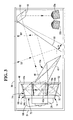
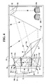
- Figs. 3 and 4 illustrate some of the ray paths from laser 12a for vertical and horizontal modes of operation, respectively.
- Fig. 5 illustrates some of the ray paths from laser 12c.
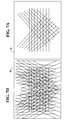
- Fig. 7a represents a partial scan pattern created by laser 12a and internal pattern mirrors 16a. This partial scan pattern includes three sets of eight lines.
- Fig. 7b represents a partial scan pattern created by laser 12b and external pattern mirrors 16b. This partial scan pattern includes three sets of eight lines.
- Fig. 7c represents a partial scan pattern created by laser 12c and external pattern mirrors 16c. This partial scan pattern includes three sets of eight lines.
- Fig. 7d represents a complete scan pattern combining the partial scan patterns of Figs. 7a-7c.
- the complete scan pattern includes 72 scan lines and line length on deck is about two hundred and thirty inches. Additional scan lines may be produced by increasing the number and orientations of pattern mirrors 16a-16c.
- a laser beam from internal facets 24a includes sections A and B .
- a laser beam from external facets 24b includes sections C and D .
- the illustrated embodiment produces a total scan line length of about 240 inches which is the sum of all the individual scan line lengths on the window.
- dual-surface polygon 14 also produces twice as many scan lines as a polygon with only one reflecting surface.
- angular coverage is increased.
- Internal and external mirror facets 24a and 24b combine to produce more output beam angles from an increased number of different input beam angles.
- Polygon 14 facilitates compact optical design, greater optical path length, and greater coverage within the scan volume.
Landscapes
- Physics & Mathematics (AREA)
- Electromagnetism (AREA)
- Engineering & Computer Science (AREA)
- Health & Medical Sciences (AREA)
- General Health & Medical Sciences (AREA)
- Toxicology (AREA)
- Artificial Intelligence (AREA)
- Computer Vision & Pattern Recognition (AREA)
- General Physics & Mathematics (AREA)
- Theoretical Computer Science (AREA)
- Mechanical Optical Scanning Systems (AREA)
Abstract
Description
- The present invention relates to optical scanners and more specifically to a barcode scanner with a dual-surface polygon.
- Optical scanners are well known for their usefulness in retail check out and inventory control. Optical scanners generally employ a laser diode, the light from which is focused and collimated to produce a scanning beam. A mirrored polygon directs the beam against a plurality of stationary mirrors, and collects the beam after it is reflected by an item bearing a barcode label. A motor rotates the mirrored polygon, and a detector receives the returning beam. The pattern produced by such a scanner is characterized by lines oriented at various angles to one another.
- The performance of a scanner is related to total scan line length S. Total scan line length S is the sum of the lengths s of all scan lines produced by the scanner.
- Individual scan line length s is related to optical path length L and angular coverage ⊖ of the scan line,
- It would be desirable to provide a barcode scanner with a polygon that increases total scan line length S.
- According to a first aspect of the present invention there is provided a barcode scanner comprising a polygon including generally planar walls arranged in a ring having first mirrored facets facing generally towards a center of the ring and second mirrored facets facing generally away from the center of the ring, wherein both the first and second mirrored facets are arranged to direct a laser beam to produce a scan pattern.
- According to a second aspect of the present invention there is provided a polygon for use in a barcode scanner comprising generally planar walls arranged in a ring having first mirrored facets facing generally towards a center of the ring and second mirrored facets facing generally away from the center of the ring, wherein the first and second mirrored facets are arranged to direct a laser beam to produce a scan pattern.
- According to a third aspect of the present invention there is provided a method of scanning an item having a barcode label comprising the steps of directing a first laser beam at inward facing mirrored facets of a ring of walls of a polygon directing a second laser beam at outward facing mirrored facets of the ring reflecting the first laser beam by the inward facing mirrored facets to form first scan lines of a scan pattern; and reflecting the second laser beam by the outward facing mirrored facets to form second scan lines of a scan pattern.
- According to a fourth aspect of the present invention there is provided a method of scanning an item having a barcode label comprising the steps of: directing a first laser beam at inward facing mirrored facets of a ring of walls of a polygon; directing a second laser beam at outward facing mirrored facets of the ring; reflecting the first laser beam by the inward facing mirrored facets towards a first set of pattern mirrors; reflecting the second laser beam by the outward facing mirrored facets towards a second set of pattern mirrors; reflecting the first laser beam by the first set of pattern mirrors to form first scan lines of a scan pattern; reflecting the second laser beam by the second set of pattern mirrors to form second scan lines of the scan pattern; collecting first light from the item by the first set of pattern mirrors; collecting second light from the item by the second set of pattern mirrors; directing the first light towards the inward facing mirrored facets of the polygon by the first set of pattern mirrors; directing the second light towards the outward facing mirrored facets of the polygon by the second set of pattern mirrors; reflecting the first light towards a first collector inside the ring by the inward facing mirrored facets of the polygon; reflecting the second light towards a second collector outside the ring by the outward facing mirrored facets of the polygon; directing the first light towards a first detector by the first collector; directing the second light towards a second detector by the second collector; converting the first light into first electrical signals by the first detector; converting the second light into second electrical signals by the second detector; and obtaining barcode label information from the first and second electrical signals by control circuitry.
- Furthermore, in accordance with the teachings of the present invention, a barcode scanner with a dual-surface polygon is provided.
- The barcode scanner includes a polygon including generally planar walls arranged in a ring having first mirrored facets facing generally towards a center of the ring and second mirrored facets facing generally away from the center of the ring. The first and second mirrored facets direct a laser beam to produce a scan pattern.
- An embodiment of the present invention will now be described, by way of example, with reference to the accompanying drawings, in which:
- Fig. 1 is a block diagram of a scanner with a dual-surface polygon;
- Fig. 2 is a top view of the optical scanner with the lid removed and showing laser beam paths;
- Fig. 3 is a right side view of the optical scanner in a first configuration and showing laser beam paths from the inner spinner facets;
- Fig. 4 is a right side view of the optical scanner in a second configuration and showing laser beam paths from the inner spinner facets;
- Fig. 5 is a right side view of the optical scanner showing laser beam paths from the external spinner facets;
- Fig. 6 is an end view of the optical scanner;
- Figs. 7a-7d are views of the scan pattern produced by the optical scanner; and
- Fig. 8 is a diagrammatic view illustrating the increase in optical path length created by the optical scanner.
-
- Referring to Fig. 1,
scanner 10 primarily includeslasers 12a-12c, dual-surface polygon 14,pattern mirrors 16a-16c,collectors 18a-18c,detectors 20a-20b, andcontrol circuitry 22. -
Lasers 12a-12c produce laser beams. Lasers 12a-12c include a laser as well as collimating elements. Laser 12a is scanned off ofinternal facets 24a ofpolygon 14, whilelasers 12b-12c is scanned off ofexternal facets 24b ofpolygon 14. - Dual-
surface polygon 14 directs the laser beams towardspatter mirrors 16a-16c and directs captured light reflected fromitem 30 towardscollectors 18a-18c. Specifically,internal facets 24a face generally inward towards a center ofpolygon 14 and direct a laser beam fromlaser 12a towardspattern mirrors 16a.External facets 24b face generally outward and away from the center ofpolygon 14 and direct laser beams fromlasers 12b-12c towardspattern mirrors 16b-16c, respectively. - Collection occurs in reverse.
Internal facets 24a direct collected light towardscollector 18a.Collector 18a directs collected light towardsdetector 20a.External facets 24b direct collected light towardscollectors 18b-18c.Collectors 18b-c direct collected light towardsdetector 20b. -
Motor 28 rotates dual-surface polygon 14. - Pattern mirrors 16a-16c direct the laser beams towards
barcode 32 ofitem 30 as scan lines.Pattern mirrors 16a-16c also capture the light reflected fromitem 30 and direct it to dual-surface polygon 14. -
Collectors 18a-18c collect the reflected light and focus it ondetectors 20a-20b. Specifically,collector 18a collects light frominternal facets 24a and focus it ondetector 20a.Collectors 18b-18c collect light fromexternal facets 24b and focus it ondetector 20b. -
Detectors 20a-20b produce electrical signals from the collected light. -
Control circuitry 22 controls operation ofscanner 10 and decodes barcode information in the electrical signals fromdetectors 20a-20b. - As described,
scanner 10 provides substantial power and performance, but the present invention also envisions fewer components combined withpolygon 14. In the present embodiment, threelasers 12a-12c could be replaced by a single laser and a beam splitter. Polygon 14 may be employed in other scanners using fewer components, such as a single laser, a single set of pattern mirrors, a single collector, and a single detector. - With reference to Figs. 2-6,
scanner 10 is shown in more detail. -
Scanner 10 includesperimeter walls 34. Dimensions ofscanner 10 are approximately six and a half inches in width, six and a half inches in length, and three inches in depth. -
Scanner 10 also includesaperture 36 in the outer surface ofscanner 10.Aperture 36 is approximately four inches wide and five inches long, with length aligned to the scan path. -
Scanner 10 may be mounted in a checkout counter in horizontal fashion, or mounted above the checkout counter in a vertical fashion as a presentation scanner. When mounted in horizontal fashion,scanner 10 may be equipped with a load cell assembly. If so,aperture 36 would be part of a weigh plate. - Polygon 14 rotates around
laser 12a andcollector 18a. Polygon 14 is mounted with its centerline generally parallel to aperture 36 for compactness and for proper scan line orientation.Polygon 14 is shown with eight generallyplanar walls 70 arranged in aring 74, although other polygon shapes are also envisioned. Each of the eightwalls 70 is oriented at a different angle frombase 72 to increase coverage in the scan volume. In the illustrated embodiment, the angles are all obtuse.Internal facets 24a ofwalls 70 face generally towards the center ofpolygon 14.External facets 24b ofwalls 70 face generally away from the center ofpolygon 14. -
Internal laser 12a andcollector 18a may be located withinring 74.Laser 12a andcollector 18a are stationary. The laser beam fromlaser 12a passes through anaperture 40a in collectingmirror 18a. -
External laser 12b andcollector 18b are mounted on one side ofpolygon 14 andexternal laser 12c andcollector 18c are mounted on the other.Collectors apertures - Internal pattern mirrors 16a are mounted in front of
polygon 14 so as to form a partial shell or cone. Internal pattern mirrors 16a preferably include three mirrors, acenter mirror 42, aleft side mirror 44, and aright side mirror 46. Mirrors 44-46 are oriented at approximately the same angle frommirror 42.Mirror 42 produces a substantially horizontal scan line.Mirrors - External pattern mirrors 16b and 16c each preferably include three mirrors. Pattern mirrors 16b include
mirrors mirrors -
Mirrors Mirrors
Mirrors - Internal and external pattern mirrors 16a-16c direct their laser beams toward
secondary mirror 60.Secondary mirror 60 directs the laser beams up and out ofscanner 10 to form a scan pattern abovescanner 10.Secondary mirror 60 also collects reflected light from scanneditem 30 and directs it to internal and external pattern mirrors 16a-16c. - With reference to Figs. 3 and 4,
secondary mirror 60 is a large, angularly adjustable, piano-mirror used to optimize the exiting angle of the scanner's entire pattern for maximum performance in either the vertical or horizontal scan modes. - In the vertical scan mode (Fig. 3), the exiting angle is preferably about seventy degrees to eighty-five degrees.
Secondary mirror 60 is oriented about ⊖ degrees shallower than in the horizontal mode of operation, where ⊖ is preferably about fifteen degrees. - In the horizontal scan mode (Fig. 4), the exiting angle is preferably about fifty-five degrees to seventy degrees.
- Reflecting
mirror 62 directs collected light fromcollector 18a todetector 20a. Reflecting mirrors 64 and 66 direct collected light fromcollectors detector 20b.Lasers detector 20b. - Figs. 2-5 also illustrate some of the ray paths for creating the scan pattern.
- Fig. 2 illustrates some of the ray paths from all three of
lasers 12a-12c. Figs. 3 and 4 illustrate some of the ray paths fromlaser 12a for vertical and horizontal modes of operation, respectively. Fig. 5 illustrates some of the ray paths fromlaser 12c. - With reference to Figs. 7a-7d, the scan pattern produced by
scanner 10 is illustrated in detail. - Fig. 7a represents a partial scan pattern created by
laser 12a and internal pattern mirrors 16a. This partial scan pattern includes three sets of eight lines. - Fig. 7b represents a partial scan pattern created by
laser 12b and external pattern mirrors 16b. This partial scan pattern includes three sets of eight lines. - Fig. 7c represents a partial scan pattern created by
laser 12c and external pattern mirrors 16c. This partial scan pattern includes three sets of eight lines. - Fig. 7d represents a complete scan pattern combining the partial scan patterns of Figs. 7a-7c. The complete scan pattern includes 72 scan lines and line length on deck is about two hundred and thirty inches. Additional scan lines may be produced by increasing the number and orientations of pattern mirrors 16a-16c.
- With reference to Fig. 8, the advantages associated with use of
polygon 14 are made clear. - A laser beam from
internal facets 24a includes sections A and B. The optical path length Li produced by anindividual facet 24b is - A laser beam from
external facets 24b includes sections C and D. The optical path length Le produced by anindividual facet 24b is - The combined optical path length L equals the sums of the individual optical path lengths Li and Le:
individual facets - Since two facets, one internal and one external, simultaneously produce scan lines, dual-
surface polygon 14 also produces twice as many scan lines as a polygon with only one reflecting surface. - Also, angular coverage is increased. Internal and
external mirror facets -
Polygon 14 facilitates compact optical design, greater optical path length, and greater coverage within the scan volume. - Although the invention has been described with particular reference to certain preferred embodiments thereof, variations and modifications of the present invention can be effected within the scope of the present invention.
Claims (13)
- A barcode scanner comprising a polygon including generally planar walls arranged in a ring having first mirrored facets facing generally towards a center of the ring and second mirrored facets facing generally away from the center of the ring, wherein both the first and second mirrored facets are arranged to direct a laser beam to produce a scan pattern.
- A barcode scanner, as claimed in claim 1, comprising a first laser mounted inside the ring for producing a first laser beam; a first collector mounted inside the ring for collecting first light reflected from a scanned bar code; a second laser mounted outside the ring for producing a second laser beam; a second collector mounted outside the ring for collecting second light reflected from said bar code; a number of detectors for converting the first and second light from the first collector into electrical signals; and pattern mirrors arranged to create a scan pattern from the first and second laser beams; wherein the first mirrored facets direct the first laser beam towards the pattern mirrors and direct the first light reflected back from the scanned bar code towards the first collector; and wherein the second mirrored facets direct the second laser beam towards the pattern mirrors and direct the second light reflected from the scanned bar code towards the second collector.
- The barcode scanner of claim 1 or claim 2, wherein the polygon comprises eight walls, each wall including a first mirrored facet and a second mirrored facet.
- The barcode scanner of any preceding claim, wherein the polygon is arranged to rotate.
- The barcode scanner of any preceding claim, further comprising a third laser mounted outside the ring for producing a third laser beam; and a third collector mounted outside the ring for collecting third light reflected back from the scanned bar code.
- The barcode scanner of any preceding claim, wherein the pattern mirrors further include a third group of pattern mirrors for reflecting the third laser beam.
- The barcode scanner of any preceding claim, wherein the pattern mirrors comprise a rotatable pattern mirror arranged to adjusting the scan pattern.
- The barcode scanner of any preceding claim, further comprising control circuitry for obtaining barcode information from the electrical signals from the number of detectors.
- A polygon for use in a barcode scanner comprising generally planar walls arranged in a ring having first mirrored facets facing generally towards a center of the ring and second mirrored facets facing generally away from the center of the ring, wherein the first and second mirrored facets are arranged to direct a laser beam to produce a scan pattern.
- The polygon of claim 9, further comprising a generally planar base portion coupled to each of the facets.
- The polygon of claim 9 or claim 10, wherein the facets are oriented at obtuse angles to the base portion.
- A method of scanning an item having a barcode label comprising the steps of:directing a first laser beam at inward facing mirrored facets of a ring of walls of a polygon;directing a second laser beam at outward facing mirrored facets of the ring;reflecting the first laser beam by the inward facing mirrored facets to form first scan lines of a scan pattern; andreflecting the second laser beam by the outward facing mirrored facets to form second scan lines of a scan pattern.
- A method of scanning an item having a barcode label comprising the steps of:directing a first laser beam at inward facing mirrored facets of a ring of walls of a polygon;directing a second laser beam at outward facing mirrored facets of the ring;reflecting the first laser beam by the inward facing mirrored facets towards a first set of pattern mirrors;reflecting the second laser beam by the outward facing mirrored facets towards a second set of pattern mirrors;reflecting the first laser beam by the first set of pattern mirrors to form first scan lines of a scan pattern;reflecting the second laser beam by the second set of pattern mirrors to form second scan lines of the scan pattern;collecting first light from the item by the first set of pattern mirrors;collecting second light from the item by the second set of pattern mirrors;directing the first light towards the inward facing mirrored facets of the polygon by the first set of pattern mirrors;directing the second light towards the outward facing mirrored facets of the polygon by the second set of pattern mirrors;reflecting the first light towards a first collector inside the ring by the inward facing mirrored facets of the polygon;reflecting the second light towards a second collector outside the ring by the outward facing mirrored facets of the polygon;directing the first light towards a first detector by the first collector;directing the second light towards a second detector by the second collector;converting the first light into first electrical signals by the first detector;converting the second light into second electrical signals by the second detector; andobtaining barcode label information from the first and second electrical signals by control circuitry.
Applications Claiming Priority (2)
| Application Number | Priority Date | Filing Date | Title |
|---|---|---|---|
| US656782 | 2003-09-05 | ||
| US10/656,782 US7073716B2 (en) | 2003-09-05 | 2003-09-05 | Barcode scanner with dual-surface polygon |
Publications (3)
| Publication Number | Publication Date |
|---|---|
| EP1513096A2 true EP1513096A2 (en) | 2005-03-09 |
| EP1513096A3 EP1513096A3 (en) | 2006-01-25 |
| EP1513096B1 EP1513096B1 (en) | 2010-02-17 |
Family
ID=34136716
Family Applications (1)
| Application Number | Title | Priority Date | Filing Date |
|---|---|---|---|
| EP04020728A Expired - Lifetime EP1513096B1 (en) | 2003-09-05 | 2004-09-01 | Barcode scanner with dual-surface polygon |
Country Status (4)
| Country | Link |
|---|---|
| US (1) | US7073716B2 (en) |
| EP (1) | EP1513096B1 (en) |
| JP (1) | JP4546192B2 (en) |
| DE (1) | DE602004025537D1 (en) |
Families Citing this family (4)
| Publication number | Priority date | Publication date | Assignee | Title |
|---|---|---|---|---|
| US8056810B2 (en) * | 2006-07-12 | 2011-11-15 | Ncr Corporation | Methods and apparatus for generating and decoding scan patterns using multiple laser sources |
| US9370342B2 (en) * | 2008-09-05 | 2016-06-21 | Carnegie Mellon University | Multi-linked endoscopic device with spherical distal assembly |
| US8733651B2 (en) * | 2012-07-30 | 2014-05-27 | Ncr Corporation | Low profile tri-aperture optical code scanner |
| US9625709B1 (en) | 2015-09-29 | 2017-04-18 | Datalogic Usa, Inc. | Reduced windage prismatic polygonal reflector for scanning |
Citations (3)
| Publication number | Priority date | Publication date | Assignee | Title |
|---|---|---|---|---|
| US3626091A (en) | 1969-12-11 | 1971-12-07 | Hughes Aircraft Co | Image converter |
| US4795224A (en) | 1986-10-06 | 1989-01-03 | Katsuchika Goto | Optical scanning pattern generator |
| JPH09325290A (en) | 1996-06-04 | 1997-12-16 | Matsushita Electric Ind Co Ltd | Scanning optics |
Family Cites Families (10)
| Publication number | Priority date | Publication date | Assignee | Title |
|---|---|---|---|---|
| US3758187A (en) * | 1971-06-09 | 1973-09-11 | Kms Ind Inc | Method and apparatus for recording intelligence on a sheet material |
| US5268565A (en) * | 1989-10-16 | 1993-12-07 | Fujitsu Limited | Compact type bar code reader |
| JPH03191317A (en) * | 1989-12-20 | 1991-08-21 | Canon Inc | Scanning optical device |
| JP2897194B2 (en) * | 1990-03-02 | 1999-05-31 | 富士通株式会社 | Reader |
| JPH07200714A (en) * | 1993-12-28 | 1995-08-04 | Nec Corp | Optical symbol reader |
| NL9401302A (en) * | 1994-08-11 | 1996-03-01 | Scantech Bv | Barcode scanner. |
| US5821520A (en) * | 1995-04-28 | 1998-10-13 | Symbol Technologies, Inc. | Bar code scanning system with the pre-decoding signal processing and method for bar code candidate selection for decoding |
| US5867298A (en) * | 1996-12-16 | 1999-02-02 | Eastman Kodak Company | Dual format pre-objective scanner |
| FR2761111B1 (en) | 1997-03-20 | 2000-04-07 | Schlumberger Services Petrol | METHOD AND APPARATUS FOR ACQUIRING DATA IN A HYDROCARBON WELL |
| US6292285B1 (en) * | 1999-12-20 | 2001-09-18 | Xerox Corporation | Single rotating polygon mirror with v-shaped facets for a multiple beam ROS |
-
2003
- 2003-09-05 US US10/656,782 patent/US7073716B2/en not_active Expired - Lifetime
-
2004
- 2004-09-01 EP EP04020728A patent/EP1513096B1/en not_active Expired - Lifetime
- 2004-09-01 DE DE602004025537T patent/DE602004025537D1/en not_active Expired - Lifetime
- 2004-09-06 JP JP2004258437A patent/JP4546192B2/en not_active Expired - Lifetime
Patent Citations (3)
| Publication number | Priority date | Publication date | Assignee | Title |
|---|---|---|---|---|
| US3626091A (en) | 1969-12-11 | 1971-12-07 | Hughes Aircraft Co | Image converter |
| US4795224A (en) | 1986-10-06 | 1989-01-03 | Katsuchika Goto | Optical scanning pattern generator |
| JPH09325290A (en) | 1996-06-04 | 1997-12-16 | Matsushita Electric Ind Co Ltd | Scanning optics |
Also Published As
| Publication number | Publication date |
|---|---|
| JP4546192B2 (en) | 2010-09-15 |
| JP2005085272A (en) | 2005-03-31 |
| EP1513096B1 (en) | 2010-02-17 |
| US7073716B2 (en) | 2006-07-11 |
| DE602004025537D1 (en) | 2010-04-01 |
| US20050051631A1 (en) | 2005-03-10 |
| EP1513096A3 (en) | 2006-01-25 |
Similar Documents
| Publication | Publication Date | Title |
|---|---|---|
| CA2170934C (en) | Optical scanners having dual surface optical elements for dual working ranges | |
| US8408469B2 (en) | Laser scanning assembly having an improved scan angle-multiplication factor | |
| US5859417A (en) | Optical scanners having dual surface optical elements for dual working ranges | |
| US7198195B2 (en) | Multiple plane scanning system for data reading applications | |
| US7588187B2 (en) | Non-imaging light collector for electro-optical scanner | |
| US6290135B1 (en) | Multiple source/dense pattern optical scanner | |
| EP1330771B1 (en) | Dense pattern optical scanner | |
| EP1513096B1 (en) | Barcode scanner with dual-surface polygon | |
| US7137560B2 (en) | Optical scanner | |
| US5315428A (en) | Optical scanning system comprising optical chopper | |
| WO2018014521A1 (en) | Multi-directional bar code scanning device having multiple laser emitters matched with single photosensitive receiver | |
| US20090001168A1 (en) | Barcode scanner including a multi-tasking pattern mirror | |
| US7178734B1 (en) | Barcode scanner including a multitasking pattern mirror | |
| US5975418A (en) | Bar code scanner with increased number of scanning beams having different directions | |
| US6774366B1 (en) | Image integration and multiple laser source projection | |
| EP0458334A1 (en) | Bar code reading apparatus | |
| JP3866321B2 (en) | Optical scanner | |
| CN206039550U (en) | Many laser emission pipe matches multi -direction barcode reader of single photosensitive receiver tube | |
| JPH0690364B2 (en) | Laser light scanning / light receiving device | |
| JPH1153461A (en) | Bar code reader | |
| JPH0312286B2 (en) | ||
| JPH08147401A (en) | Optical scanner |
Legal Events
| Date | Code | Title | Description |
|---|---|---|---|
| PUAI | Public reference made under article 153(3) epc to a published international application that has entered the european phase |
Free format text: ORIGINAL CODE: 0009012 |
|
| AK | Designated contracting states |
Kind code of ref document: A2 Designated state(s): AT BE BG CH CY CZ DE DK EE ES FI FR GB GR HU IE IT LI LU MC NL PL PT RO SE SI SK TR |
|
| AX | Request for extension of the european patent |
Extension state: AL HR LT LV MK |
|
| PUAL | Search report despatched |
Free format text: ORIGINAL CODE: 0009013 |
|
| AK | Designated contracting states |
Kind code of ref document: A3 Designated state(s): AT BE BG CH CY CZ DE DK EE ES FI FR GB GR HU IE IT LI LU MC NL PL PT RO SE SI SK TR |
|
| AX | Request for extension of the european patent |
Extension state: AL HR LT LV MK |
|
| 17P | Request for examination filed |
Effective date: 20060725 |
|
| AKX | Designation fees paid |
Designated state(s): DE FR GB |
|
| 17Q | First examination report despatched |
Effective date: 20070228 |
|
| GRAP | Despatch of communication of intention to grant a patent |
Free format text: ORIGINAL CODE: EPIDOSNIGR1 |
|
| GRAS | Grant fee paid |
Free format text: ORIGINAL CODE: EPIDOSNIGR3 |
|
| GRAA | (expected) grant |
Free format text: ORIGINAL CODE: 0009210 |
|
| AK | Designated contracting states |
Kind code of ref document: B1 Designated state(s): DE FR GB |
|
| REG | Reference to a national code |
Ref country code: GB Ref legal event code: FG4D |
|
| REG | Reference to a national code |
Ref country code: GB Ref legal event code: 746 Effective date: 20100301 |
|
| REF | Corresponds to: |
Ref document number: 602004025537 Country of ref document: DE Date of ref document: 20100401 Kind code of ref document: P |
|
| REG | Reference to a national code |
Ref country code: DE Ref legal event code: R096 Ref document number: 602004025537 Country of ref document: DE Effective date: 20100401 |
|
| REG | Reference to a national code |
Ref country code: DE Ref legal event code: R084 Ref document number: 602004025537 Country of ref document: DE Effective date: 20100811 |
|
| PLBE | No opposition filed within time limit |
Free format text: ORIGINAL CODE: 0009261 |
|
| STAA | Information on the status of an ep patent application or granted ep patent |
Free format text: STATUS: NO OPPOSITION FILED WITHIN TIME LIMIT |
|
| 26N | No opposition filed |
Effective date: 20101118 |
|
| REG | Reference to a national code |
Ref country code: DE Ref legal event code: R097 Ref document number: 602004025537 Country of ref document: DE Effective date: 20101118 |
|
| REG | Reference to a national code |
Ref country code: FR Ref legal event code: PLFP Year of fee payment: 13 |
|
| REG | Reference to a national code |
Ref country code: FR Ref legal event code: PLFP Year of fee payment: 14 |
|
| REG | Reference to a national code |
Ref country code: FR Ref legal event code: PLFP Year of fee payment: 15 |
|
| P01 | Opt-out of the competence of the unified patent court (upc) registered |
Effective date: 20230512 |
|
| PGFP | Annual fee paid to national office [announced via postgrant information from national office to epo] |
Ref country code: GB Payment date: 20230927 Year of fee payment: 20 |
|
| PGFP | Annual fee paid to national office [announced via postgrant information from national office to epo] |
Ref country code: FR Payment date: 20230925 Year of fee payment: 20 Ref country code: DE Payment date: 20230927 Year of fee payment: 20 |
|
| REG | Reference to a national code |
Ref country code: GB Ref legal event code: 732E Free format text: REGISTERED BETWEEN 20240418 AND 20240424 |
|
| REG | Reference to a national code |
Ref country code: DE Ref legal event code: R081 Ref document number: 602004025537 Country of ref document: DE Owner name: NCR VOYIX CORP., ATLANTA, US Free format text: FORMER OWNER: NCR INTERNATIONAL, INC., DAYTON, OHIO, US |
|
| REG | Reference to a national code |
Ref country code: DE Ref legal event code: R071 Ref document number: 602004025537 Country of ref document: DE |
|
| REG | Reference to a national code |
Ref country code: GB Ref legal event code: PE20 Expiry date: 20240831 |
|
| PG25 | Lapsed in a contracting state [announced via postgrant information from national office to epo] |
Ref country code: GB Free format text: LAPSE BECAUSE OF EXPIRATION OF PROTECTION Effective date: 20240831 |
|
| PG25 | Lapsed in a contracting state [announced via postgrant information from national office to epo] |
Ref country code: GB Free format text: LAPSE BECAUSE OF EXPIRATION OF PROTECTION Effective date: 20240831 |