EP1512868B1 - Method and device for controlling an actuator for a starter - Google Patents
Method and device for controlling an actuator for a starter Download PDFInfo
- Publication number
- EP1512868B1 EP1512868B1 EP20040016882 EP04016882A EP1512868B1 EP 1512868 B1 EP1512868 B1 EP 1512868B1 EP 20040016882 EP20040016882 EP 20040016882 EP 04016882 A EP04016882 A EP 04016882A EP 1512868 B1 EP1512868 B1 EP 1512868B1
- Authority
- EP
- European Patent Office
- Prior art keywords
- control device
- starter
- actuator
- signal
- control
- Prior art date
- Legal status (The legal status is an assumption and is not a legal conclusion. Google has not performed a legal analysis and makes no representation as to the accuracy of the status listed.)
- Expired - Lifetime
Links
- 238000000034 method Methods 0.000 title claims description 92
- 239000007858 starting material Substances 0.000 title claims description 60
- 230000008569 process Effects 0.000 claims description 23
- 238000004590 computer program Methods 0.000 claims description 12
- 230000004044 response Effects 0.000 claims description 5
- 230000005540 biological transmission Effects 0.000 claims description 4
- 238000002485 combustion reaction Methods 0.000 claims description 3
- 230000003139 buffering effect Effects 0.000 claims description 2
- 239000003990 capacitor Substances 0.000 claims description 2
- 230000008878 coupling Effects 0.000 claims description 2
- 238000010168 coupling process Methods 0.000 claims description 2
- 238000005859 coupling reaction Methods 0.000 claims description 2
- 238000001514 detection method Methods 0.000 claims 1
- 230000009191 jumping Effects 0.000 claims 1
- 238000012423 maintenance Methods 0.000 claims 1
- 230000008901 benefit Effects 0.000 description 4
- 230000015654 memory Effects 0.000 description 4
- 230000004913 activation Effects 0.000 description 3
- 230000000295 complement effect Effects 0.000 description 2
- 230000003213 activating effect Effects 0.000 description 1
- 230000002411 adverse Effects 0.000 description 1
- 230000008859 change Effects 0.000 description 1
- 238000004891 communication Methods 0.000 description 1
- 230000001419 dependent effect Effects 0.000 description 1
- 230000006870 function Effects 0.000 description 1
- 230000007257 malfunction Effects 0.000 description 1
- 230000002093 peripheral effect Effects 0.000 description 1
- 230000002085 persistent effect Effects 0.000 description 1
- 230000002035 prolonged effect Effects 0.000 description 1
- 239000000725 suspension Substances 0.000 description 1
Images

Classifications
-
- F—MECHANICAL ENGINEERING; LIGHTING; HEATING; WEAPONS; BLASTING
- F02—COMBUSTION ENGINES; HOT-GAS OR COMBUSTION-PRODUCT ENGINE PLANTS
- F02N—STARTING OF COMBUSTION ENGINES; STARTING AIDS FOR SUCH ENGINES, NOT OTHERWISE PROVIDED FOR
- F02N11/00—Starting of engines by means of electric motors
- F02N11/08—Circuits or control means specially adapted for starting of engines
- F02N11/0862—Circuits or control means specially adapted for starting of engines characterised by the electrical power supply means, e.g. battery
-
- F—MECHANICAL ENGINEERING; LIGHTING; HEATING; WEAPONS; BLASTING
- F02—COMBUSTION ENGINES; HOT-GAS OR COMBUSTION-PRODUCT ENGINE PLANTS
- F02N—STARTING OF COMBUSTION ENGINES; STARTING AIDS FOR SUCH ENGINES, NOT OTHERWISE PROVIDED FOR
- F02N2300/00—Control related aspects of engine starting
- F02N2300/30—Control related aspects of engine starting characterised by the use of digital means
Definitions
- the invention relates to a control device and a method for controlling at least one actuator for a starter motor of a motor vehicle and a corresponding computer program and a data carrier with this computer program.
- controllers and methods are known in the art. All these controllers is based on the problem that when starting a motor with the help of a starter usually the supply voltage of a respective control device breaks down very heavily at least once, because the operation of the starter motor loads the supply voltage very strong. Depending on the strength of the break in the supply voltage, it is at least for a short time to switch off these devices, in particular in the case of control devices designed as microcontrollers, that is, these devices then no longer provide their output signals properly.
- the operation of the starter or the starting process of a motor to be started should preferably not be adversely affected by these voltage dips.
- a start command given by the driver in the form of a short-term tip signal is first fed to a drive-holding device.
- This drive-holding device is the start command at its output for a direct and the other indirectly via an intermediate control device, in particular a microcontroller to the starter or its actuator on. It works in such a way that the start of the starter is first initiated via the direct connection between the holding member and the starter. In the case of a normal start-up course without serious voltage dips and functional failures of the microcontroller, the latter then assumes the longer-term control of the starter during the entire starting process.
- the control unit disclosed therein comprises a controller in the form of a microcontroller having an I / O port for outputting a control signal to an actuator or a controlled system in response to a start command. It further comprises a drive holding device which is arranged between the control device, that is to say the microcontroller and the controlled system, for buffering the control signal after it has been output by the microcontroller.
- the control device comprises a feedback device for feeding back a current state of the drive-holding device back to the output port of the microcontroller or to the input of the drive-holding device.
- the proposed drive circuit causes the drive-holding device and thus also the downstream actuator undergoes no state change by a voltage dip or reset of the microcontroller. By a reset, the drive-holding device is not turned off. If it was already switched off before the reset, it will not be switched on by the reset.
- the known from the named document control unit adheres to the disadvantage that the current state of the drive-holding member, by the fed back Signal is represented by the microcontroller is not used in its decision on the further control of the actuator after its reset. Rather, decides in the disclosed circuit for the control unit, a superposition signal, which is formed from the fed-back signal and output from the microcontroller at its output port drive signal, via the control of the actuator or the starter after a reset. Characterized dominates during a reset and initialization phase of the microcontroller, the previous output state, while after the initialization of the microcontroller whose drive signal dominates.
- Such a design of the control device of the control unit has the advantage that an unintentional reconnection of the actuator is prevented after a reset of the control device, as long as not all conditions / criteria are met.
- a reset causes all outputs of the controller to be switched to ground.
- the control signal for the actuator originally output by the control device is only maintained after a reset by the drive holding device at the input of the actuator.
- the discharge-related holding time is set so short that it is insignificant in view of the unwanted prolonged turn-on of the actuator.
- the proposed method thus causes an unintentional activation of the actuator or of the starter motor after a restart of the control device is prevented.
- it is designed such that it maintains the control of the starter via the actuator not only during a first but also during a selectable number of subsequent voltage dips and associated resets of the control device.
- this has at least one switch-off output for switching off the starter via the actuator, primarily and independently of the state of the switch-on output of the control device.
- An unintentional Switching on the starter according to the invention is also prevented by the fact that the control device resumes a control of the actuator after a reset not only when the actuator is still controlled via the drive-holding device, but if in addition further criteria are met.
- the ignition or the ignition must still be turned on, a predetermined target speed at the end of the starting process (start-end speed) may not yet be reached and the number of occurred so far during the boot reset did not exceed a predetermined reset threshold.
- the above object is further achieved by a method for driving at least one actuator for a starter of a motor vehicle and a corresponding computer program and a data carrier on which this computer program is stored.
- the advantages of this method and of the computer program essentially correspond to the advantages mentioned above with regard to the control unit.
- the method also includes other measures to prevent accidental activation of the starter.
- Another measure against unintentional activation of the starter is that, as part of the starting process, when a driving condition in the form that the ignition is turned on and the current speed of the is not met, the driver's original start request is discarded by deleting the start command or a stored terminal 50 information.
- control device and the method are the subject of the dependent claims.
- FIG. 1 shows the controller 100 according to the invention. It is used to control at least one actuator 200 for a starter 300 of a motor vehicle (not shown).
- the control device 100 includes a control device 110, which is preferably designed as a microcontroller.
- the microcontroller receives at its input a start request SW, he, if further conditions (see step S7 in FIG. 2 ) are satisfied, as a start command SB in a memory, preferably a persistent RAM 111, redundant and complementary stores.
- the microcontroller 110 has a switch-on output EA, which is connected to a drive-holding device 120. The output of this drive-holding device 120 leads to the input or the base of a first switching transistor 150 for direct driving of an actuator 200.
- the actuator 200 is preferably a relay, which the starter 300 directly on or off, according to the from the microcontroller to the power-on output EA output control signal.
- the control signal is forwarded without delay to the first switching transistor 150 by the drive-holding device 120.
- the drive-holding device comprises in detail an RC element comprising a capacitor 124 and a parallel connected discharge resistor 126. One end of this parallel circuit is connected via a diode 122 to the switch-on output EA of the controller 110, while the other end of this parallel circuit after Ground is connected.
- the drive-holding device 120 comprises a decoupling resistor 128 for coupling the non-grounded end of the RC element 124, 126 to the first switching transistor 150 and the actuator 200, respectively.
- the current state of the drive-holding device 120 that is, their digital on or off state or their state of charge in a realization as an RC element to the microcontroller, preferably via an analog / digital converter (not shown), fed back.
- the tap of the feedback device 130 between the collector of the first switching transistor 150 and the actuator 200 is located.
- the drive-holding device 120 may also be attached to the output of the drive-holding device 120 or at a suitable location in its interior.
- the switch-on output EA of the microcontroller 110 is switched to ground, the starter 300 is switched off via the drive-holding device 120 and the actuator 200.
- this switch-off signal is only supplied to the actuator by the drive-holding device with a time delay passed to bridge the reset time of the computer.
- the microcontroller 110 preferably has at least one switch-off output AA.
- a turn-off signal at this output then turns off the starter 300 immediately.
- the control device further comprises a switch-off logic module 160, which has an OR gate 162 and a second switching transistor 164 having.
- a first input E1 of the OR gate 162 receives the high-active turn-off signal of the microcontroller 110, and a second input E2 of the OR gate 162 receives the low-active enable signal F. These two input signals are logically combined by the OR gate 162 in such a way that a high level is present at its output when a switch-off request for the starter 300 output by the microcontroller 110 via its switch-off signal AA is present or when the enable signal F is not low-active.
- a second switching transistor 164 is driven, which is connected between ground and the input of the first switching transistor 150. By means of this second switching transistor, the input of the first switching transistor 150 is switched to ground in response to the output signal A of the OR gate 162 when the starter 300 is to be turned off.
- the driver To start the engine of a motor vehicle, the driver first activates the ignition lock of his motor vehicle by bringing it into a first possible position, represented by a terminal 15 signal (method step S1). Subsequently, the inventive method checks in the context of an initialization in a second method step S2, the presence of a plurality of conditions. Under these conditions, it is checked whether 1) a starter of the vehicle for starting the engine is possibly still active from a previous starting operation, whether 2) a so-called start command whose Generation is explained below, is still active and whether 3) the contents of a reset counter is less than a predetermined threshold. Conditions 1) and 2) are both mandatory; the 3) condition is optional.
- the query is answered according to method step S2 with "no" and the method then checks in a method step S3, whether the driver, the ignition not only in the first position for switching on the ignition, but also in a third position for activating the starter has turned.
- a start request issued externally by the driver is indicated to the control unit 110 by an active so-called terminal-50 signal.
- step S3 If it is determined in method step S3 that the terminal 50 signal or the KL50 signal stored as a start request is no longer active, then the control unit 100 assumes that a starting operation has already been successfully carried out in the past, so that such a currently no longer necessary. The method then goes into normal operation of the internal combustion engine of the vehicle according to method step S4. If the terminal 50 signal is still active, the method proceeds from step S3 to step S5, in which it is checked whether the speed of the internal combustion engine falls below a predetermined minimum speed or not. If it is determined in method step S5 that the engine speed is greater than the predetermined threshold value Sn in the form of the minimum engine speed, then it is again assumed that the starting operation has occurred in the past successfully completed; the method then goes into normal operation according to method step S4.
- method step S5 if it has been determined in method step S5 that the engine speed has not yet reached the predetermined threshold value Sn in the form of the minimum engine speed, the control unit 100 and in particular the controller 110 interprets the present situation as the driver's start request and activates a corresponding internal signal; this takes place in method step S6.
- a subsequent method step S7 a plurality of conditions are again checked, which are OR-linked with one another. Depending on whether at least one of these conditions is met, the starter is actuated according to method step S8 or a start-up procedure currently carried out according to method step S10 is aborted.
- the conditions which are checked in method step S7 involve the question as to whether the engine speed is greater than a predefined speed threshold Sn, whether the time during which the internal signal "starter active" activated in method step S6 has already been longer than a predetermined threshold time St is active or whether there is a frictional connection between the starter and a wheel of the vehicle, indicated for example by an engaged gear.
- the starter is either driven for the first time or maintained in its function.
- a so-called start command SB is then generated and stored or it remains stored if it has already been saved before.
- the start command is redundant, that is, for security reasons distributed to multiple memories stored.
- the start command SB generated or maintained according to method step S8a should not be confused with the signal "starter active" generated in method step S6. The difference is that the start command SB according to method step S8a is only satisfied if at least one of the conditions according to method step S7 is not fulfilled.
- the reset counter is incremented once in method step S8b.
- the ignition is switched on for the first time, it can be assumed that the reset counter was previously set to zero.
- the state of the reset counter after incrementing according to method step S8b is subsequently compared in method step S9 with a predetermined reset counter threshold value Sz.
- This threshold for the reset counter represents the maximum number of allowed during a boot reset or voltage dips of the controller.
- step S9 If it is determined in step S9 that this threshold Sz has not yet been reached, then the startup process is continued. More precisely, the method then branches into a so-called starter operating loop, which then branches to the beginning of method step S7 described above.
- the starter operating loop comprising the method steps S7, S8 and S9 is run through as long as the state of the reset counter is smaller than the predetermined one Counter threshold value Sz and none of the conditions according to method step S7 is satisfied.
- method step S9 If, however, it is determined in method step S9 that the status of the reset counter has reached the preset counter threshold value Sz, then the starting process in the form of the drive loop is discontinued; instead, the actuator 200 is shut down for the starter via the output A-A of the controller 110 and the method branches on the assumption that the previously dropped voltage across the actuator 200 has recovered to the beginning of the method step S2 described above. It is then checked again whether all conditions are met according to method step S2. If this is not the case, the method subsequently executes method step S3 and then proceeds as described above. If, however, all the conditions according to method step S2 are fulfilled, this means that a starting process already initiated in the past has not yet ended.
- the starting process is therefore continued, possibly even before the predetermined by the drive-holding device 120 hold time has expired.
- the control device 110 then generates the signal "starter active" according to method step S6. It then subsequently checks the conditions described above in accordance with method step S7 and re-activates the trigger holding device 120 via its E-A output if none of the discharge conditions according to method step S7 has been fulfilled. In contrast to the restart of the engine described above primarily now the starter is not first started according to step S8, but it remains activated.
- step S7 it is ascertained that at least one of them checked there Conditions is satisfied, the method branches from step S7 to step S10.
- step S10a There is a possibly still active startup process via the output AA of the controller 110 is stopped immediately.
- the starter is dropped and it is the redundant previously stored in step S8a stored start command now redundant (step S10a).
- step S10b the reset counter is reset to zero.
- method step S10 it is fundamentally assumed that the starting process has been completed successfully and it is therefore subsequently branched off after method step S4, that is to say the normal mode.
- control device 110 after a caused by the breaking of the supply voltage temporary shutdown, again initialized itself for the generation and output of the control signal, detects the current state of the drive-holding device by checking whether the control command is active, and in dependence thereon as well as in dependence of the further criteria according to the method steps S2 and S7 decides whether it resumes the actuation of the actuator or not.
- the method just described is preferably realized in the form of a computer program for a control device for controlling an actuator for a starter.
- the computer program is optionally stored together with other computer programs on a computer-readable medium.
- the data medium may be a floppy disk, a compact disc, a flash memory or the like.
- the computer program stored on the data carrier can then be sold as a product to a customer.
- the computer program is transmitted to a customer and sold even without the aid of the data carrier via an electronic communication network, in particular the Internet.
Landscapes
- Engineering & Computer Science (AREA)
- Chemical & Material Sciences (AREA)
- Combustion & Propulsion (AREA)
- Mechanical Engineering (AREA)
- General Engineering & Computer Science (AREA)
- Combined Controls Of Internal Combustion Engines (AREA)
- Control Of Electric Motors In General (AREA)
Description
Die Erfindung betrifft ein Steuergerät und ein Verfahren zum Ansteuern von mindestens einem Stellglied für einen Startermotor eines Kraftfahrzeugs sowie ein entsprechendes Computerprogramm und einen Datenträger mit diesem Computerprogramm.The invention relates to a control device and a method for controlling at least one actuator for a starter motor of a motor vehicle and a corresponding computer program and a data carrier with this computer program.
Im Stand der Technik sind verschiedene derartige Steuergeräte und Verfahren bekannt. All diesen Steuergeräten liegt die Problematik zugrunde, dass beim Anlassen eines Motors mit Hilfe eines Starters in der Regel die Versorgungsspannung einer jeweiligen Steuereinrichtung mindestens einmal sehr stark einbricht, weil der Betrieb des Startermotor die Versorgungsspannung sehr stark belastet. Je nach Stärke des Einbrechens der Versorgungsspannung kommt es insbesondere bei als Mikrocontroller ausgebildeten Steuereinrichtungen mindestens kurzzeitig zum Abschalten dieser Einrichtungen, das heißt diese Einrichtungen stellen dann ihre Ausgangssignale nicht mehr ordnungsgemäß bereit. Der Betrieb des Starters beziehungsweise der Startvorgang eines zu startenden Motors soll jedoch vorzugsweise durch diese Spannungseinbrüche nicht nachteilig beeinflusst werden.Various such controllers and methods are known in the art. All these controllers is based on the problem that when starting a motor with the help of a starter usually the supply voltage of a respective control device breaks down very heavily at least once, because the operation of the starter motor loads the supply voltage very strong. Depending on the strength of the break in the supply voltage, it is at least for a short time to switch off these devices, in particular in the case of control devices designed as microcontrollers, that is, these devices then no longer provide their output signals properly. However, the operation of the starter or the starting process of a motor to be started should preferably not be adversely affected by these voltage dips.
Hier setzt eine erste aus der
Eine weitere Schaltung und ein weiteres Verfahren zur Aufrechterhaltung der Ansteuerung von Peripherieelementen durch Mikroprozessoren ist zum Beispiel aus der
Dem aus der benannten Druckschrift bekannten Steuergerät haftet jedoch der Nachteil an, dass der aktuelle Zustand des Ansteuer-Halte-Gliedes, der durch das rückgekoppelte Signal repräsentiert wird, von dem Mikrocontroller nicht bei seiner Entscheidung über die weitere Ansteuerung des Stellglieds nach seinem Reset herangezogen wird. Vielmehr entscheidet bei der offenbarten Schaltung für das Steuergerät ein Superpositionssignal, welches aus dem rückgekoppeltem Signal und dem von dem Mikrocontroller an seinem Ausgangs-Port ausgegebenen Ansteuersignal gebildet wird, über die Ansteuerung des Stellglieds beziehungsweise des Starters nach einem Reset. Dadurch dominiert während einer Reset- und Initialisierungsphase des Mikrocontrollers der vorhergehende Ausgangszustand, während nach der Initialisierung des Mikrocontrollers dessen Ansteuersignal dominiert.However, the known from the named document control unit adheres to the disadvantage that the current state of the drive-holding member, by the fed back Signal is represented by the microcontroller is not used in its decision on the further control of the actuator after its reset. Rather, decides in the disclosed circuit for the control unit, a superposition signal, which is formed from the fed-back signal and output from the microcontroller at its output port drive signal, via the control of the actuator or the starter after a reset. Characterized dominates during a reset and initialization phase of the microcontroller, the previous output state, while after the initialization of the microcontroller whose drive signal dominates.
Ausgehend von diesem Stand der Technik ist es deshalb die Aufgabe der Erfindung, ein bekanntes Steuergerät, Verfahren und Computerprogramm zum Ansteuern von mindestens einem Stellglied für einen Starter derart weiterzubilden, dass die Ansteuerung des Starters nach einem Reset und damit eine Fortsetzung des Startvorganges nur dann erfolgt, wenn dies insgesamt sinnvoll erscheint.Based on this prior art, it is therefore the object of the invention to develop a known control device, method and computer program for driving at least one actuator for a starter such that the control of the starter after a reset and thus a continuation of the starting process only takes place if that makes sense overall.
Diese Aufgabe wird durch den in Patentanspruch 1 beanspruchten Gegenstand gelöst. Demnach erfolgt die Lösung dieser Aufgabe für das oben genannte Steuergerät in der Weise, dass dessen Steuereinrichtung ausgebildet ist, nach einem temporären Einbrechen ihrer Versorgungsspannung und einer dadurch bedingten temporären Abschaltung der Steuereinrichtung aufgrund einer danach wieder regenerierten Versorgungsspannung wieder aktiviert wird und ausgebildet ist dann zu entscheiden, die Ansteuerung des Stellglieds über die Ansteuer-Halteeinrichtung wieder aufzunehmen, wenn als eine erste Bedingung das Stellglied zu dem Zeitpunkt der Entscheidung noch von dem durch die Ansteuer-Halteeinrichtung vor dem Einbrechen der Versorgungsspannung zwischengespeicherten Steuersignal angesteuert wird und als eine zweite Bedingung der ebenfalls vor Einbruch der Versorgungsspannung zwischengespeicherte Startbefehl nach dem Einbruch der Versorgungsspannung immer noch gespeichert ist.This object is solved by the claimed in claim 1 subject. Accordingly, the solution of this task for the above-mentioned control unit in such a way that its control device is formed, after a temporary collapse of their supply voltage and a consequent temporary shutdown of the controller due to a then regenerated supply voltage is activated again and is then to decide to resume the drive of the actuator via the drive-holding device when, as a first condition, the actuator at the time of the decision nor by the by the drive-holding device before breaking the Supply voltage is stored cached control signal and as a second condition of the cached also before the supply voltage start command after the onset of supply voltage is still stored.
Eine derartige Ausbildung der Steuereinrichtung des Steuergeräts bietet den Vorteil, dass ein ungewolltes Wiedereinschalten des Stellglieds nach einem Reset der Steuereinrichtung verhindert wird, solange nicht alle Bedingungen/Kriterien erfüllt sind. Ein Reset bewirkt, dass alle Ausgänge der Steuereinrichtung nach Masse geschaltet werden. Das ursprünglich von der Steuereinrichtung ausgegebene Steuersignal für das Stellglied wird nach einem Reset lediglich noch von der Ansteuer-Halteeinrichtung am Eingang des Stellglied aufrechterhalten. Für die Ansteuer-Halteeinrichtung wird jedoch vorzugsweise die Entladebeziehungsweise Haltezeit so kurz eingestellt, dass sie im Hinblick auf das ungewollte verlängerte Einschalten des Stellglieds unbeachtlich ist. Das vorgeschlagene Verfahren bewirkt also, dass ein ungewolltes Ansteuern des Stellglieds beziehungsweise des Anlassmotors nach einem Wiedereinschalten der Steuereinrichtung verhindert wird. Gleichzeitig ist es so ausgebildet, dass es die Ansteuerung des Starters über das Stellglied nicht nur während eines ersten, sondern auch während einer wählbaren Anzahl nachfolgender Spannungseinbrüche und damit verbundener Resets der Steuereinrichtung aufrechterhält.Such a design of the control device of the control unit has the advantage that an unintentional reconnection of the actuator is prevented after a reset of the control device, as long as not all conditions / criteria are met. A reset causes all outputs of the controller to be switched to ground. The control signal for the actuator originally output by the control device is only maintained after a reset by the drive holding device at the input of the actuator. However, for the drive-holding means, preferably, the discharge-related holding time is set so short that it is insignificant in view of the unwanted prolonged turn-on of the actuator. The proposed method thus causes an unintentional activation of the actuator or of the starter motor after a restart of the control device is prevented. At the same time, it is designed such that it maintains the control of the starter via the actuator not only during a first but also during a selectable number of subsequent voltage dips and associated resets of the control device.
Gemäß einer ersten vorteilhaften Ausgestaltung des beanspruchten Steuergeräts weist dieses mindestens einen Ausschalt-Ausgang auf zum Ausschalten des Starters über das Stellglied, vorrangig und unabhängig von dem Zustand des Einschalt-Ausgangs der Steuereinrichtung. Ein ungewolltes Einschalten des Starters wird erfindungsgemäß auch dadurch verhindert, dass die Steuereinrichtung eine Ansteuerung des Stellglieds nach einem Reset nicht nur dann wiederaufnimmt, wenn das Stellglied über die Ansteuer-Halteeinrichtung noch angesteuert wird, sondern wenn zusätzlich weitere Kriterien erfüllt sind. So muss insbesondere die Zündung beziehungsweise das Zündschloss noch eingeschaltet sein, darf eine vorgegebene Solldrehzahl am Ende des Startvorganges (Startende-Drehzahl) noch nicht erreicht sein und die Anzahl der bisher während des Startvorgangs aufgetretenen Resets einen vorgegebenen Reset-Schwellenwert nicht überschritten haben.According to a first advantageous embodiment of the claimed controller, this has at least one switch-off output for switching off the starter via the actuator, primarily and independently of the state of the switch-on output of the control device. An unintentional Switching on the starter according to the invention is also prevented by the fact that the control device resumes a control of the actuator after a reset not only when the actuator is still controlled via the drive-holding device, but if in addition further criteria are met. Thus, in particular, the ignition or the ignition must still be turned on, a predetermined target speed at the end of the starting process (start-end speed) may not yet be reached and the number of occurred so far during the boot reset did not exceed a predetermined reset threshold.
Die oben genannte Aufgabe wird weiterhin durch ein Verfahren zum Ansteuern von mindestens einem Stellglied für einen Starter eines Kraftfahrzeugs sowie ein entsprechendes Computerprogramm und einen Datenträger, auf dem dieses Computerprogramm gespeichert ist, gelöst. Die Vorteile dieses Verfahrens und des Computerprogramms entsprechen im Wesentlichen den oben in Bezug auf das Steuergerät genannten Vorteilen.The above object is further achieved by a method for driving at least one actuator for a starter of a motor vehicle and a corresponding computer program and a data carrier on which this computer program is stored. The advantages of this method and of the computer program essentially correspond to the advantages mentioned above with regard to the control unit.
Darüber hinaus umfasst das Verfahren jedoch auch weitere Maßnahmen, um ein ungewolltes Ansteuern des Starters zu verhindern. So sieht es zum Beispiel eine redundante Speicherung eines von dem Fahrer gegebenen Startsignals (Klemme 50-Signal) oder eines daraus abgeleiteten Startbefehls in unterschiedlichen Speicherbereichen oder in unterschiedlichen Mikrocontrollern, vorzugsweise in komplementärer Form vor, um eine spätere Überprüfung des Vorliegens des Startbefehls absichern zu können. Eine weitere Maßnahme gegen ungewolltes Ansteuern des Starters besteht darin, dass im Rahmen des Startvorganges dann, wenn eine Ansteuerbedingung in der Form, dass das Zündschloss eingeschaltet ist und die aktuelle Drehzahl des zu startenden Motors eine vorgegebene Startende-Drehzahl noch nicht erreicht hat, nicht erfüllt ist, der ursprüngliche Startwunsch des Fahrers verworfen wird, indem der Startbefehl beziehungsweise eine gespeicherte Klemme-50-Information gelöscht wird. Schließlich besteht eine weitere erfindungsgemäße Maßnahme zum Absichern gegen ein ungewolltes Ansteuern in der Bereitstellung eines Reset-Zählers zum Zählen der Anzahl der während eines Startvorganges aufgetretenen Resets, wobei der Mikrocontroller den Starter nur dann nach einem Reset wieder erneut ansteuert, wenn die bisher während des Startvorganges aufgetretenen Resets einen vorgegebenen Reset-Schwellenwert noch nicht überschritten haben.In addition, however, the method also includes other measures to prevent accidental activation of the starter. For example, redundant storage of a start signal given by the driver (
Weitere vorteilhafte Ausgestaltungen des Steuergerätes und des Verfahrens sind Gegenstand der abhängigen Ansprüche.Further advantageous embodiments of the control device and the method are the subject of the dependent claims.
Die Erfindung wird nachfolgend in Form verschiedener Ausführungsbeispiele unter Bezugnahme auf die der Beschreibung beigefügten Figuren detailliert beschrieben, wobei
- Figur 1
- den Aufbau des erfindungsgemäßen Steuergerätes; und
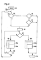
- Figur 2
- das erfindungsgemäße Verfahren
- FIG. 1
- the structure of the control device according to the invention; and
- FIG. 2
- the inventive method
Erfindungsgemäß wird der aktuelle Zustand der Ansteuer-Halteeinrichtung 120, das heißt deren digitaler Ein- oder Aus-Zustand oder deren Ladezustand bei einer Realisierung als RC-Glied auf den Mikrocontroller, vorzugsweise über einen Analog/Digital-Wandler (nicht gezeigt), zurückgekoppelt. In
Er kann jedoch auch am Ausgang der Ansteuer-Halteeinrichtung 120 oder an einer geeigneten Stelle in deren Innerem angebracht sein.However, it may also be attached to the output of the drive-holding
Wenn zum Beispiel aufgrund eines Resets der Einschalt-Ausgang E-A des Mikrocontrollers 110 nach Masse geschaltet wird, erfolgt ein Ausschalten des Starters 300 über die Ansteuer-Halteeinrichtung 120 und das Stellglied 200. Dieses Ausschaltsignal wird jedoch von der Ansteuer-Halteeinrichtung nur zeitverzögert an das Stellglied weitergegeben, um die Resetzeit des Rechners zu überbrücken.If, for example, due to a reset, the switch-on output EA of the
Um eine derartige Zeitverzögerung umgehen zu können und den Starter bei Bedarf unverzögert und vorrangig und unabhängig von dem Zustand der Ansteuerhalteschaltung ausschalten zu können, weist der Mikrocontroller 110 vorzugsweise mindestens einen Ausschalt-Ausgang A-A auf. Ein Ausschaltsignal an diesem Ausgang schaltet dann den Starter 300 unverzüglich aus. Um sicher zu gewährleisten, dass der Starter auch bei Fehlverhalten des Mikrocomputers nicht während eines Kraftschlusses im Getriebe betätigt wird, ist es vorteilhaft, wenn zusätzlich ein Freigabesignal F, bei Automatikgetrieben das Parken/Normal-Signal und bei Handschaltgetrieben das Kupplungssignal zur hardwaremäßigen Abschaltung des Starters vorhanden ist. Zur Realisierung einer derartigen Schaltungslogik umfasst das Steuergerät weiterhin ein Ausschalt-Logik-Modul 160, welches ein Oder-Gatter 162 sowie einen zweiten Schalttransistor 164 aufweist. Ein erster Eingang E1 des Oder-Gatters 162 empfängt das high-aktive Ausschalt-Signal des Mikrocontrollers 110 und ein zweiter Eingang E2 des Oder-Gatter 162 empfängt das low-aktive Freigabesignal F. Diese beiden Eingangssignale werden durch das Oder-Gatter 162 logisch verknüpft, so dass an dessen Ausgang ein high-Pegel anliegt, wenn ein von dem Mikrocontroller 110 über sein Ausschaltsignal A-A ausgegebener Ausschaltwunsch für den Starter 300 vorliegt oder wenn das Freigabesignal F nicht low-aktiv ist. Mit dem Ausgangssignal A des Oder-Gatters 162 wird ein zweiter Schalttransistor 164 angesteuert, der zwischen Masse und den Eingang des ersten Schalttransistors 150 geschaltet ist. Mit Hilfe dieses zweiten Schalttransistors wird der Eingang des ersten Schalttransistors 150 im Ansprechen auf das Ausgangssignal A des Oder-Gatters 162 nach Masse geschaltet, wenn der Starter 300 ausgeschaltet werden soll.In order to be able to avoid such a time delay and to be able to switch off the starter without delay and with priority and independently of the state of the drive hold circuit, the
Das der Erfindung zugrunde liegende Verfahren zum Ansteuern von mindestens einem Stellglied 200 für einen Starter 300 eines Kraftfahrzeugs über die Steuereinrichtung 110 wird nachfolgend detailliert unter Bezugnahme auf die
Zum Starten des Motors eines Kraftfahrzeugs aktiviert der Fahrer zunächst das Zündschloss seines Kraftfahrzeugs, indem er dieses in eine erste mögliche Stellung, repräsentiert durch ein Klemme-15-Signal, bringt (Verfahrensschritt S1). Nachfolgend prüft das erfindungsgemäße Verfahren im Rahmen einer Initialisierung in einem zweiten Verfahrensschritt S2 das Vorliegen einer Mehrzahl von Bedingungen. Bei diesen Bedingungen wird geprüft, ob 1) ein Starter des Fahrzeugs zum Starten des Motors eventuell aus einem vorangegangenen Startvorgang noch aktiv ist, ob 2) ein sogenannter Startbefehl, dessen Generierung weiter unten erläutert wird, noch aktiv ist und ob 3) der Inhalt eines Reset-Zählers kleiner als ein vorgegebener Schwellenwert ist. Die Bedingungen 1) und 2) sind beide zwingend erforderlich; die 3) Bedingung ist optional. Bei einem neuerlichen beziehungsweise erstmaligem Starten des Fahrzeugs ist bereits die genannte erste Bedingungen nicht erfüllt, was zur Folge hat, dass die beiden anderen, mit der ersten UND-verknüpften Bedingung. nicht mehr weiter geprüft werden müssen. In diesem Fall wird die Abfrage gemäß Verfahrensschritt S2 mit "nein" beantwortet und das Verfahren prüft dann in einem Verfahrensschritt S3, ob der Fahrer das Zündschloss nicht nur in die erste Position zum Einschalten der Zündung, sondern auch in eine dritte Position zum Aktivieren des Starters gedreht hat. Ein solcher von dem Fahrer extern geäußerter Startwunsch wird dem Steuergerät 110 durch ein aktives sogenanntes Klemme-50-Signal angezeigt. Wird in Verfahrensschritt S3 festgestellt, dass das Klemme-50-Signal oder das als Startwunsch gespeicherte KL50-Signal nicht mehr aktiv ist, so geht das Steuergerät 100 davon aus, dass ein Startvorgang in der Vergangenheit bereits erfolgreich durchgeführt wurde, so dass ein solcher zum derzeitigen Zeitpunkt nicht mehr erforderlich ist. Das Verfahren geht dann in einen Normalbetrieb der Brennkraftmaschine des Fahrzeugs gemäß Verfahrensschritt S4 über. Sollte das Klemme-50-Signal noch aktiv sein, so geht das Verfahren von Verfahrensschritt S3 nach Verfahrensschritt S5 über, in welchem überprüft wird, ob die Drehzahl der Brennkraftmaschine eine vorgegebene minimale Drehzahl unterschreitet oder nicht. Wird in Verfahrensschritt S5 festgestellt, dass die Drehzahl der Brennkraftmaschine größer als der vorgegebene Schwellenwert Sn in Form der minimalen Drehzahl ist, so wird wiederum angenommen, dass der Startvorgang in der Vergangenheit erfolgreich abgeschlossen wurde; das Verfahren geht dann in den Normalbetrieb gemäß Verfahrensschritt S4 über.To start the engine of a motor vehicle, the driver first activates the ignition lock of his motor vehicle by bringing it into a first possible position, represented by a terminal 15 signal (method step S1). Subsequently, the inventive method checks in the context of an initialization in a second method step S2, the presence of a plurality of conditions. Under these conditions, it is checked whether 1) a starter of the vehicle for starting the engine is possibly still active from a previous starting operation, whether 2) a so-called start command whose Generation is explained below, is still active and whether 3) the contents of a reset counter is less than a predetermined threshold. Conditions 1) and 2) are both mandatory; the 3) condition is optional. If the vehicle is restarted for the first time or the first time, the first conditions mentioned above are not met, which means that the other two have the first AND-linked condition. no longer need to be tested. In this case, the query is answered according to method step S2 with "no" and the method then checks in a method step S3, whether the driver, the ignition not only in the first position for switching on the ignition, but also in a third position for activating the starter has turned. Such a start request issued externally by the driver is indicated to the
Wurde jedoch in Verfahrensschritt S5 festgestellt, dass die Drehzahl der Brennkraftmaschine den vorgegebenen Schwellenwert Sn in Form der minimalen Drehzahl noch nicht erreicht hat, so interpretiert das Steuergerät 100 und insbesondere die Steuereinrichtung 110 die vorliegende Situation als Startwunsch des Fahrers und aktiviert ein entsprechendes internes Signal; dies geschieht in Verfahrensschritt S6. In einem nachfolgenden Verfahrensschritt S7 werden wiederum eine Mehrzahl von Bedingungen abgeprüft, welche miteinander ODER-verknüpft sind. Je nachdem, ob mindestens eine dieser Bedingungen erfüllt ist, wird der Starter gemäß Verfahrensschritt S8 angesteuert oder es wird ein aktuell durchgeführter Startvorgang gemäß Verfahrensschritt S10 abgebrochen. Bei den Bedingungen, welche in Verfahrensschritt S7 überprüft werden, handelt es sich um die Frage, ob die Drehzahl der Brennkraftmaschine größer als eine vorgegebene Drehzahlschwelle Sn, ob die Zeit, während welcher das in Verfahrensschritt S6 aktivierte interne Signal "Starter aktiv" bereits länger als eine vorgegebene Schwellenzeit St aktiv ist oder ob ein Kraftschluss zwischen dem Starter und einem Rad des Fahrzeugs, angezeigt zum Beispiel durch einen eingelegten Gang, besteht.However, if it has been determined in method step S5 that the engine speed has not yet reached the predetermined threshold value Sn in the form of the minimum engine speed, the
Wenn, wie bereits oben erwähnt, mindestens eine der in Verfahrensschritt S7 überprüften Bedingungen nicht erfüllt ist, also zum Beispiel die Drehzahl der Brennkraftmaschine noch kleiner als die vorgegebene Schwellendrehzahl Sn ist, wird der Starter entweder erstmalig angesteuert oder in seiner Funktion aufrechterhalten. Im Inneren der Steuereinrichtung 110 wird dann ein sogenannter Startbefehl SB generiert und gespeichert beziehungsweise er bleibt gespeichert, wenn er bereits vorher gespeichert wurde. In jedem Fall wird der Startbefehl redundant, das heißt aus Sicherheitsgründen verteilt auf mehrere Speicher, abgespeichert. Der gemäß Verfahrensschritt S8a generierte beziehungsweise aufrechterhaltene Startbefehl SB ist nicht zu verwechseln mit dem in Verfahrensschritt S6 generierten Signal "Starter aktiv". Der Unterschied besteht darin, dass der Startbefehl SB gemäß Verfahrensschritt S8a erst dann erfüllt wird, wenn mindestens eine der Bedingungen gemäß Verfahrensschritt S7 nicht erfüllt ist.If, as already mentioned above, at least one of the conditions checked in method step S7 is not fulfilled, that is, for example, the engine speed is still lower than the predetermined threshold speed Sn, the starter is either driven for the first time or maintained in its function. Inside the
Im Rahmen der Starteransteuerung beziehungsweise im Rahmen der Aufrechterhaltung des Startvorgangs wird in Verfahrensschritt S8b der Reset-Zähler einmalig inkrementiert. Bei einem erstmaligen Einschalten der Zündung kann davon ausgegangen werden, dass der Reset-Zähler zuvor mit null vorgesetzt war. Der Stand des Reset-Zählers nach dem Inkrementieren gemäß Verfahrensschritt S8b wird nachfolgend in Verfahrensschritt S9 mit einem vorgegebenen Reset-Zählerschwellenwert Sz verglichen. Dieser Schwellenwert für den Reset-Zähler repräsentiert die maximale Anzahl von während eines Startvorgangs zulässigen Resets beziehungsweise Spannungseinbrüchen der Steuereinrichtung.As part of the starter control or in the context of maintaining the startup process, the reset counter is incremented once in method step S8b. When the ignition is switched on for the first time, it can be assumed that the reset counter was previously set to zero. The state of the reset counter after incrementing according to method step S8b is subsequently compared in method step S9 with a predetermined reset counter threshold value Sz. This threshold for the reset counter represents the maximum number of allowed during a boot reset or voltage dips of the controller.
Wenn in Verfahrensschritt S9 festgestellt wird, dass dieser Schwellenwert Sz noch nicht erreicht ist, dann wird der Startvorgang weiter fortgesetzt. Genauer gesagt verzweigt dann das Verfahren in eine sogenannte Starterbetriebsschleife, welche dann auf den Beginn des oben beschriebenen Verfahrensschrittes S7 verzweigt. Die Starterbetriebsschleife umfassend die Verfahrensschritt S7, S8 und S9 wird so lange durchlaufen, wie der Stand des Reset-Zählers kleiner als der vorgegebene Zählerschwellenwert Sz ist und keine der Bedingungen gemäß Verfahrensschritt S7 erfüllt ist.If it is determined in step S9 that this threshold Sz has not yet been reached, then the startup process is continued. More precisely, the method then branches into a so-called starter operating loop, which then branches to the beginning of method step S7 described above. The starter operating loop comprising the method steps S7, S8 and S9 is run through as long as the state of the reset counter is smaller than the predetermined one Counter threshold value Sz and none of the conditions according to method step S7 is satisfied.
Wird jedoch in Verfahrensschritt S9 festgestellt, dass der Stand des Reset-Zählers den vorgegebenen Zählerschwellenwert Sz erreicht hat, so wird der Startvorgang in Form der Antriebsschleife nicht weiter fortgesetzt; stattdessen erfolgt ein Abschalten des Stellglieds 200 für den Starter über den Ausgang A-A der Steuereinrichtung 110 und das Verfahren verzweigt unter der Voraussetzung, dass sich die zuvor eingebrochene Spannung über dem Stellglied 200 wieder erholt hat, auf den Anfang des oben beschriebenen Verfahrensschrittes S2. Es wird dann erneut geprüft, ob alle Bedingungen gemäß Verfahrensschritt S2 erfüllt sind. Sollte dies nicht der Fall sein, so führt das Verfahren nachfolgend Verfahrensschritt S3 aus und verfährt dann wie oben beschrieben. Sollten jedoch alle Bedingungen gemäß Verfahrensschritt S2 erfüllt sein, so bedeutet dies, dass ein bereits in der Vergangenheit eingeleiteter Startvorgang noch nicht beendet ist. Der Startvorgang wird deshalb fortgesetzt, gegebenenfalls noch bevor die von der Ansteuer-Halteeinrichtung 120 vorgegebene Haltezeit abgelaufen ist. Die Steuereinrichtung 110 generiert dann von sich aus das Signal "Starter aktiv" gemäß Verfahrensschritt S6. Sie prüft dann nachfolgend die oben beschriebenen Bedingungen gemäß Verfahrensschritt S7 und steuert die Ansteuer-Halteeinrichtung 120 über ihren E-A-Ausgang erneut an, wenn keine der Abwurfbedingungen gemäß Verfahrensschritt S7 erfüllt ist. Im Unterschied zu dem oben primär beschriebenen Neustart des Motors wird nun der Starter gemäß Verfahrensschritt S8 nicht erstmalig gestartet, sondern vielmehr bleibt er aktiviert.If, however, it is determined in method step S9 that the status of the reset counter has reached the preset counter threshold value Sz, then the starting process in the form of the drive loop is discontinued; instead, the
Wird jedoch irgendwann in Verfahrensschritt S7 festgestellt, dass mindestens eine der dort überprüften Bedingungen erfüllt ist, so verzweigt das Verfahren von Verfahrensschritt S7 nach Verfahrensschritt S10. Dort wird ein eventuell noch aktiver Startvorgang über den Ausgang A-A der Steuereinrichtung 110 sofort abgebrochen. Der Starter wird abgeworfen und es wird der zuvor in Verfahrensschritt S8a redundant gespeicherte Startbefehl nun redundant gelöscht (Verfahrensschritt S10a). Außerdem wird gemäß Verfahrensschritt S10b der Reset-Zähler auf null zurückgesetzt. In Verfahrensschritt S10 wird grundsätzlich davon ausgegangen, dass der Startvorgang erfolgreich beendet wurde und es wird deshalb nachfolgend nach Verfahrensschritt S4, das heißt den Normalbetrieb, verzweigt.However, at some point in method step S7, it is ascertained that at least one of them checked there Conditions is satisfied, the method branches from step S7 to step S10. There is a possibly still active startup process via the output AA of the
Insgesamt dauert das Durchlaufen des Verfahrens gemäß
Das soeben beschriebene Verfahren wird vorzugsweise in Form eines Computerprogramms für ein Steuergerät zum Ansteuern von einem Stellglied für einen Starter realisiert. Im Falle einer solchen Softwarerealisierung ist es möglich, dass das Computerprogramm gegebenenfalls zusammen mit weiteren Computerprogrammen auf einem computerlesbaren Datenträger abgespeichert wird. Bei dem Datenträger kann es sich um eine Diskette, eine Compact-Disc, einen Flash-Memory oder dergleichen handeln. Das auf dem Datenträger abgespeicherte Computerprogramm kann dann als Produkt an einen Kunden verkauft werden.The method just described is preferably realized in the form of a computer program for a control device for controlling an actuator for a starter. In the case of such a software implementation, it is possible that the computer program is optionally stored together with other computer programs on a computer-readable medium. The data medium may be a floppy disk, a compact disc, a flash memory or the like. The computer program stored on the data carrier can then be sold as a product to a customer.
Im Falle einer solchen Softwarelösung ist es weiterhin möglich, dass das Computerprogramm auch ohne die Zuhilfenahme des Datenträgers über ein elektronisches Kommunikationsnetzwerk, insbesondere das Internet, an einen Kunden übertragen und verkauft wird.In the case of such a software solution, it is also possible that the computer program is transmitted to a customer and sold even without the aid of the data carrier via an electronic communication network, in particular the Internet.
Claims (14)
- Control unit (100) for controlling at least one actuator (200) for a starter (300) of a motor vehicle, comprising:- a control device (110) having a switch-on output (E-A) for outputting a control signal to the actuator (200) in response to a starting instruction (SB) for starting the starter (300);- an actuation-hold device (120) arranged between the control device (110) and the actuator (200) for buffering the control signal after it has been output by the control device (110); and- a feedback device (130) for feeding back a current state of the actuation-hold device (120) to the control device (110),characterized in that, after a temporary dip in the supply voltage of the control device (110) and temporary switching off of the control device (110) as a result of this, said control device (110) is reactivated on the basis of a supply voltage which is subsequently regenerated again, and said control device (110) is designed to decide, within the scope of an initialization, to resume the actuation of the actuator (200) via the actuation-hold device (120) if, as a first condition, the actuator (200) is still controlled at the time of the decision by the control signal which is buffered by the actuation-hold device (120) before the dip in the supply voltage, and, as a second condition, the starting instruction (SB) which is also buffered before the dip in the supply voltage is still stored after the dip in the supply voltage.
- Control unit (100) according to Claim 1, characterized in that the control device (110) is designed as a microcontroller.
- Control unit (100) according to Claim 1 or 2, characterized in that the actuation-hold device (120) has:- a timer element (124, 126) which is embodied as an RC element composed of a capacitor (124) and a discharge resistor (126) which is connected in parallel, wherein one end of the parallel circuit is connected via a diode (122) to the switch-on output (E-A) of the control device (110), and the other end of the parallel circuit is connected to earth; and- a decoupling resistor (128) for coupling the end of the timer element (124, 126) which has not been connected to earth to the actuator (200) via a first switching transistor (150).
- Control unit (100) according to one of the preceding claims, characterized in that the control device (110) has at least one switch-off output (A-A) for switching off the starter (300) via the actuator (200) with priority and independently of the state of the switch-on output (E-A) of the control device (110).
- Control unit (100) according to Claim 4, characterized by a switch-off logic module (160) comprising:- an OR gate (162), one input (E1) of which receives an output signal of the switch-off output (A-A) of the control device (110), and the other input (E2) of which receives an enable signal (F) for enabling the switch-off process, in order to generate an output signal (A) which represents the logic OR combination of the two input signals; and- a second switching transistor (164) which is connected between earth and the input of the first switching transistor (150) and has the purpose of switching off the starter via the actuator (200) in response to the output signal (A) of the OR gate (162).
- Control unit (100) according to Claim 5, characterized in that the enable signal (F) is the park signal or normal signal in the case of motor vehicles with an automatic transmission.
- Method for controlling at least one actuator (200) for a starter (300) of a motor vehicle via a control device (110), comprising the following steps:- generation of a control signal by the control device (110) for starting the starter (300) in response to a starting instruction (SB);- holding of the control signal after its generation at the input of the actuator (200); and- detection and recording of whether there has been a temporary dip in the supply voltage for the control device (110) during the operation of the starter (300), and as a result the generation and outputting of the control signal by the control device (110) have been stopped,characterized by- resumption of the actuation of the actuator (200) by the control device (110) if, after a temporary dip in the supply voltage of the control device (110), it is detected within the scope of an initialization that, as a first condition, the previously generated control signal is still present at the input of the actuator (200) on the basis of the hold function, and, as a second condition, the starting instruction (SB) which has also been previously stored is still stored after the dip (S2).
- Method according to Claim 7, characterized in that a further condition for the resumption of the actuation is met if the current state of a reset counter which represents the number of dips in the supply voltage which have already occurred in the past does not exceed a predefined threshold value S2 (S2).
- Method according to Claim 7 or 8, characterized in that the resumption of the actuation of the actuator (200) comprises the following steps:- generation of a control-device-internal signal "starter active" which represents a still applicable starting wish by the driver (S6);- checking (S7), on the basis of abort conditions, whether a starting process which has been begun in the past and is currently still being carried out is to be continued further or aborted;- continuation of the starting process including maintenance of preferably redundant storage of the starting instruction and incrementation of a reset counter (S8, S8a, S8b), if none of the abort conditions is met;- checking whether the reading of the incremented reset counter has exceeded a predefined counter threshold value (SZ); and- jumping back to the start of the checking step (S7) if the reading of the reset counter has not yet passed the threshold value (SZ).
- Method according to Claim 9, characterized by renewed checking of the conditions for the resumption of the actuation (S2), if the reading of the reset counter has passed the threshold value (SZ).
- Method according to Claim 9 or 10, characterized in that the abort conditions are met (S7), if- the rotational speed of the internal combustion engine has exceeded a predefined threshold rotational speed (Sn);- the time during which the starter was already active, represented by the "starter active" signal, has exceeded a predefined time threshold value; or- frictional engagement is observed between the starter and the wheel.
- Method according to Claim 11, characterized in that the starting process is terminated and the system goes into a normal operating mode, if at least one of the abort conditions is met (S10).
- Computer program with program code for a control unit (100) for controlling at least one actuator (200) for a starter of a motor vehicle, characterized in that the program code is designed to carry out the method according to one of Claims 7-12.
- Data carrier with program code according to Claim 13.
Applications Claiming Priority (2)
| Application Number | Priority Date | Filing Date | Title |
|---|---|---|---|
| DE2003140701 DE10340701A1 (en) | 2003-09-04 | 2003-09-04 | Control device and method for driving an actuator for a starter motor |
| DE10340701 | 2003-09-04 |
Publications (3)
| Publication Number | Publication Date |
|---|---|
| EP1512868A2 EP1512868A2 (en) | 2005-03-09 |
| EP1512868A3 EP1512868A3 (en) | 2006-09-06 |
| EP1512868B1 true EP1512868B1 (en) | 2009-10-14 |
Family
ID=34129639
Family Applications (1)
| Application Number | Title | Priority Date | Filing Date |
|---|---|---|---|
| EP20040016882 Expired - Lifetime EP1512868B1 (en) | 2003-09-04 | 2004-07-16 | Method and device for controlling an actuator for a starter |
Country Status (2)
| Country | Link |
|---|---|
| EP (1) | EP1512868B1 (en) |
| DE (2) | DE10340701A1 (en) |
Families Citing this family (5)
| Publication number | Priority date | Publication date | Assignee | Title |
|---|---|---|---|---|
| DE102006016893A1 (en) * | 2006-04-11 | 2007-10-25 | Robert Bosch Gmbh | Method and device for controlling the starter of a motor vehicle |
| JP5003768B2 (en) | 2009-01-16 | 2012-08-15 | 株式会社デンソー | Starter control device |
| DE102019209805A1 (en) * | 2019-07-04 | 2021-01-07 | Robert Bosch Gmbh | Battery module for a motor vehicle and motor vehicle |
| KR20220130516A (en) * | 2021-03-18 | 2022-09-27 | 주식회사 엘지에너지솔루션 | Relay control apparatus, battery pack and electric vehicle |
| CN113467527B (en) * | 2021-06-28 | 2023-03-24 | 华润电力湖南有限公司 | Executing mechanism linkage method and device, DCS (distributed control System) and storage medium |
Family Cites Families (4)
| Publication number | Priority date | Publication date | Assignee | Title |
|---|---|---|---|---|
| JPH02119674A (en) * | 1988-10-27 | 1990-05-07 | Kubota Ltd | Engine starting controller |
| US5252861A (en) * | 1991-07-18 | 1993-10-12 | Eaton Corporation | Starter interlock for electronically controlled vehicle |
| DE19720191C1 (en) * | 1997-05-14 | 1998-04-23 | Siemens Ag | Buffer circuit for microprocessor output in motor vehicle |
| DE19844454C2 (en) * | 1998-09-28 | 2001-11-29 | Siemens Ag | Control circuit between a port of a microprocessor and an electrical consumer and method for maintaining the current state of an electrical consumer during a dip in the supply voltage |
-
2003
- 2003-09-04 DE DE2003140701 patent/DE10340701A1/en not_active Withdrawn
-
2004
- 2004-07-16 EP EP20040016882 patent/EP1512868B1/en not_active Expired - Lifetime
- 2004-07-16 DE DE200450010223 patent/DE502004010223D1/en not_active Expired - Lifetime
Also Published As
| Publication number | Publication date |
|---|---|
| DE10340701A1 (en) | 2005-03-31 |
| EP1512868A3 (en) | 2006-09-06 |
| DE502004010223D1 (en) | 2009-11-26 |
| EP1512868A2 (en) | 2005-03-09 |
Similar Documents
| Publication | Publication Date | Title |
|---|---|---|
| DE102011003872B4 (en) | Starter Controller, Idle Reduction System, Medium and Fault Determination Procedures | |
| DE102005003979B3 (en) | Device for coordinating switchable motor vehicle function(s) has different state of charge thresholds for function depending on drive unit state, energy storage unit temperature, external temperature and/or energy storage unit aging | |
| WO2011015402A1 (en) | Device to start an internal combustion engine | |
| EP1817493A1 (en) | Control circuit for a switching device | |
| DE102006053515A1 (en) | Motor vehicle with a start-stop function for an internal combustion engine and operating method therefor | |
| DE10143454B4 (en) | Device for controlling a vehicle | |
| EP0326694B1 (en) | Safety system for an internal-combustion engine | |
| EP1512868B1 (en) | Method and device for controlling an actuator for a starter | |
| DE10339464A1 (en) | Communication error detection method for a bus communication network in a vehicle | |
| EP1521917A1 (en) | Method and device for improving the functional safety when actuating a clutch and/or a transmission | |
| DE10005778A1 (en) | Circuit arrangement for control of starter relay of starter for car's IC engine has between computer and starter relay, storage circuit which is designed for maintenance of existing control signal for starter relay | |
| EP3110681B1 (en) | Method for operating a steering system | |
| DE102013203186A1 (en) | Start-stop automatic control unit for performing engine idle reduction control in vehicle, has a starter relay set to off state, starter whose driving is stopped, and microcomputer which is reset, on detecting microcomputer abnormality | |
| DE4229540C2 (en) | Method and device for controlling an internal combustion engine | |
| EP1462683B1 (en) | Device and method to control a hold magnet of a park-lock mechanism of a vehicle transmission | |
| EP1032950B1 (en) | Discharging circuit for a capacitive actuator | |
| EP1434934B1 (en) | Internal combustion engine controller and method for operating an internal combustion engine controller | |
| DE102020200203B4 (en) | Device for operating an electronic system, in particular a vehicle | |
| EP1446576B1 (en) | Starter device for an internal combustion engine | |
| DE19841659B4 (en) | Method for controlling a fuel pump for a motor vehicle | |
| DE19721386A1 (en) | Starting device for starting an internal combustion engine | |
| DE102011002157A1 (en) | Anlasseransteuervorrichtung | |
| DE102011005548A1 (en) | A start system procedure, start system, circuitry and computer program product | |
| EP0331674B1 (en) | Process for driving computer-controlled final control elements and computer coupled to a final control element | |
| EP2182197B1 (en) | Method for operating a vehicle's electronic control device |
Legal Events
| Date | Code | Title | Description |
|---|---|---|---|
| PUAI | Public reference made under article 153(3) epc to a published international application that has entered the european phase |
Free format text: ORIGINAL CODE: 0009012 |
|
| AK | Designated contracting states |
Kind code of ref document: A2 Designated state(s): AT BE BG CH CY CZ DE DK EE ES FI FR GB GR HU IE IT LI LU MC NL PL PT RO SE SI SK TR |
|
| AX | Request for extension of the european patent |
Extension state: AL HR LT LV MK |
|
| PUAL | Search report despatched |
Free format text: ORIGINAL CODE: 0009013 |
|
| AK | Designated contracting states |
Kind code of ref document: A3 Designated state(s): AT BE BG CH CY CZ DE DK EE ES FI FR GB GR HU IE IT LI LU MC NL PL PT RO SE SI SK TR |
|
| AX | Request for extension of the european patent |
Extension state: AL HR LT LV MK |
|
| 17P | Request for examination filed |
Effective date: 20070306 |
|
| AKX | Designation fees paid |
Designated state(s): DE FR GB IT |
|
| 17Q | First examination report despatched |
Effective date: 20070820 |
|
| GRAP | Despatch of communication of intention to grant a patent |
Free format text: ORIGINAL CODE: EPIDOSNIGR1 |
|
| GRAS | Grant fee paid |
Free format text: ORIGINAL CODE: EPIDOSNIGR3 |
|
| GRAA | (expected) grant |
Free format text: ORIGINAL CODE: 0009210 |
|
| AK | Designated contracting states |
Kind code of ref document: B1 Designated state(s): DE FR GB IT |
|
| REG | Reference to a national code |
Ref country code: GB Ref legal event code: FG4D Free format text: NOT ENGLISH |
|
| REF | Corresponds to: |
Ref document number: 502004010223 Country of ref document: DE Date of ref document: 20091126 Kind code of ref document: P |
|
| PLBE | No opposition filed within time limit |
Free format text: ORIGINAL CODE: 0009261 |
|
| STAA | Information on the status of an ep patent application or granted ep patent |
Free format text: STATUS: NO OPPOSITION FILED WITHIN TIME LIMIT |
|
| 26N | No opposition filed |
Effective date: 20100715 |
|
| PGFP | Annual fee paid to national office [announced via postgrant information from national office to epo] |
Ref country code: GB Payment date: 20140721 Year of fee payment: 11 |
|
| GBPC | Gb: european patent ceased through non-payment of renewal fee |
Effective date: 20150716 |
|
| PG25 | Lapsed in a contracting state [announced via postgrant information from national office to epo] |
Ref country code: GB Free format text: LAPSE BECAUSE OF NON-PAYMENT OF DUE FEES Effective date: 20150716 |
|
| REG | Reference to a national code |
Ref country code: FR Ref legal event code: PLFP Year of fee payment: 13 |
|
| REG | Reference to a national code |
Ref country code: FR Ref legal event code: PLFP Year of fee payment: 14 |
|
| PGFP | Annual fee paid to national office [announced via postgrant information from national office to epo] |
Ref country code: FR Payment date: 20170720 Year of fee payment: 14 Ref country code: IT Payment date: 20170721 Year of fee payment: 14 |
|
| PG25 | Lapsed in a contracting state [announced via postgrant information from national office to epo] |
Ref country code: FR Free format text: LAPSE BECAUSE OF NON-PAYMENT OF DUE FEES Effective date: 20180731 |
|
| PG25 | Lapsed in a contracting state [announced via postgrant information from national office to epo] |
Ref country code: IT Free format text: LAPSE BECAUSE OF NON-PAYMENT OF DUE FEES Effective date: 20180716 |
|
| PGFP | Annual fee paid to national office [announced via postgrant information from national office to epo] |
Ref country code: DE Payment date: 20220927 Year of fee payment: 19 |
|
| REG | Reference to a national code |
Ref country code: DE Ref legal event code: R119 Ref document number: 502004010223 Country of ref document: DE |
|
| PG25 | Lapsed in a contracting state [announced via postgrant information from national office to epo] |
Ref country code: DE Free format text: LAPSE BECAUSE OF NON-PAYMENT OF DUE FEES Effective date: 20240201 |