EP1512846A2 - Déphaseur d'arbre à cames avec un boítier et un élément d'entraínement formé de deux matériaux différents - Google Patents
Déphaseur d'arbre à cames avec un boítier et un élément d'entraínement formé de deux matériaux différents Download PDFInfo
- Publication number
- EP1512846A2 EP1512846A2 EP04255337A EP04255337A EP1512846A2 EP 1512846 A2 EP1512846 A2 EP 1512846A2 EP 04255337 A EP04255337 A EP 04255337A EP 04255337 A EP04255337 A EP 04255337A EP 1512846 A2 EP1512846 A2 EP 1512846A2
- Authority
- EP
- European Patent Office
- Prior art keywords
- housing
- driving element
- phaser
- rotor
- camshaft
- Prior art date
- Legal status (The legal status is an assumption and is not a legal conclusion. Google has not performed a legal analysis and makes no representation as to the accuracy of the status listed.)
- Withdrawn
Links
- 239000000463 material Substances 0.000 title claims abstract description 36
- RDYMFSUJUZBWLH-UHFFFAOYSA-N endosulfan Chemical compound C12COS(=O)OCC2C2(Cl)C(Cl)=C(Cl)C1(Cl)C2(Cl)Cl RDYMFSUJUZBWLH-UHFFFAOYSA-N 0.000 title claims abstract description 16
- 229910052782 aluminium Inorganic materials 0.000 claims abstract description 12
- XAGFODPZIPBFFR-UHFFFAOYSA-N aluminium Chemical compound [Al] XAGFODPZIPBFFR-UHFFFAOYSA-N 0.000 claims abstract description 12
- 229910000831 Steel Inorganic materials 0.000 claims abstract description 9
- 239000010959 steel Substances 0.000 claims abstract description 9
- FYYHWMGAXLPEAU-UHFFFAOYSA-N Magnesium Chemical compound [Mg] FYYHWMGAXLPEAU-UHFFFAOYSA-N 0.000 claims abstract description 7
- 229910052749 magnesium Inorganic materials 0.000 claims abstract description 7
- 239000011777 magnesium Substances 0.000 claims abstract description 7
- 238000002485 combustion reaction Methods 0.000 claims abstract description 3
- 229910052751 metal Inorganic materials 0.000 description 5
- 239000002184 metal Substances 0.000 description 5
- 239000003562 lightweight material Substances 0.000 description 4
- 239000004033 plastic Substances 0.000 description 4
- 238000001746 injection moulding Methods 0.000 description 3
- CWYNVVGOOAEACU-UHFFFAOYSA-N Fe2+ Chemical compound [Fe+2] CWYNVVGOOAEACU-UHFFFAOYSA-N 0.000 description 2
- XEEYBQQBJWHFJM-UHFFFAOYSA-N Iron Chemical compound [Fe] XEEYBQQBJWHFJM-UHFFFAOYSA-N 0.000 description 2
- 238000000034 method Methods 0.000 description 2
- 239000011248 coating agent Substances 0.000 description 1
- 238000000576 coating method Methods 0.000 description 1
- 239000013536 elastomeric material Substances 0.000 description 1
- 230000006698 induction Effects 0.000 description 1
- 238000002347 injection Methods 0.000 description 1
- 239000007924 injection Substances 0.000 description 1
- 229910052742 iron Inorganic materials 0.000 description 1
- 230000014759 maintenance of location Effects 0.000 description 1
- 150000002739 metals Chemical class 0.000 description 1
- 238000000465 moulding Methods 0.000 description 1
- 229920005989 resin Polymers 0.000 description 1
- 239000011347 resin Substances 0.000 description 1
- 239000000243 solution Substances 0.000 description 1
- 229920003002 synthetic resin Polymers 0.000 description 1
- 239000000057 synthetic resin Substances 0.000 description 1
Images

Classifications
-
- F—MECHANICAL ENGINEERING; LIGHTING; HEATING; WEAPONS; BLASTING
- F01—MACHINES OR ENGINES IN GENERAL; ENGINE PLANTS IN GENERAL; STEAM ENGINES
- F01L—CYCLICALLY OPERATING VALVES FOR MACHINES OR ENGINES
- F01L1/00—Valve-gear or valve arrangements, e.g. lift-valve gear
- F01L1/02—Valve drive
- F01L1/022—Chain drive
-
- F—MECHANICAL ENGINEERING; LIGHTING; HEATING; WEAPONS; BLASTING
- F01—MACHINES OR ENGINES IN GENERAL; ENGINE PLANTS IN GENERAL; STEAM ENGINES
- F01L—CYCLICALLY OPERATING VALVES FOR MACHINES OR ENGINES
- F01L1/00—Valve-gear or valve arrangements, e.g. lift-valve gear
- F01L1/34—Valve-gear or valve arrangements, e.g. lift-valve gear characterised by the provision of means for changing the timing of the valves without changing the duration of opening and without affecting the magnitude of the valve lift
- F01L1/344—Valve-gear or valve arrangements, e.g. lift-valve gear characterised by the provision of means for changing the timing of the valves without changing the duration of opening and without affecting the magnitude of the valve lift changing the angular relationship between crankshaft and camshaft, e.g. using helicoidal gear
- F01L1/3442—Valve-gear or valve arrangements, e.g. lift-valve gear characterised by the provision of means for changing the timing of the valves without changing the duration of opening and without affecting the magnitude of the valve lift changing the angular relationship between crankshaft and camshaft, e.g. using helicoidal gear using hydraulic chambers with variable volume to transmit the rotating force
-
- F—MECHANICAL ENGINEERING; LIGHTING; HEATING; WEAPONS; BLASTING
- F01—MACHINES OR ENGINES IN GENERAL; ENGINE PLANTS IN GENERAL; STEAM ENGINES
- F01L—CYCLICALLY OPERATING VALVES FOR MACHINES OR ENGINES
- F01L1/00—Valve-gear or valve arrangements, e.g. lift-valve gear
- F01L1/02—Valve drive
- F01L1/024—Belt drive
-
- F—MECHANICAL ENGINEERING; LIGHTING; HEATING; WEAPONS; BLASTING
- F01—MACHINES OR ENGINES IN GENERAL; ENGINE PLANTS IN GENERAL; STEAM ENGINES
- F01L—CYCLICALLY OPERATING VALVES FOR MACHINES OR ENGINES
- F01L1/00—Valve-gear or valve arrangements, e.g. lift-valve gear
- F01L1/34—Valve-gear or valve arrangements, e.g. lift-valve gear characterised by the provision of means for changing the timing of the valves without changing the duration of opening and without affecting the magnitude of the valve lift
- F01L1/344—Valve-gear or valve arrangements, e.g. lift-valve gear characterised by the provision of means for changing the timing of the valves without changing the duration of opening and without affecting the magnitude of the valve lift changing the angular relationship between crankshaft and camshaft, e.g. using helicoidal gear
- F01L1/3442—Valve-gear or valve arrangements, e.g. lift-valve gear characterised by the provision of means for changing the timing of the valves without changing the duration of opening and without affecting the magnitude of the valve lift changing the angular relationship between crankshaft and camshaft, e.g. using helicoidal gear using hydraulic chambers with variable volume to transmit the rotating force
- F01L2001/3445—Details relating to the hydraulic means for changing the angular relationship
- F01L2001/34453—Locking means between driving and driven members
-
- F—MECHANICAL ENGINEERING; LIGHTING; HEATING; WEAPONS; BLASTING
- F01—MACHINES OR ENGINES IN GENERAL; ENGINE PLANTS IN GENERAL; STEAM ENGINES
- F01L—CYCLICALLY OPERATING VALVES FOR MACHINES OR ENGINES
- F01L2301/00—Using particular materials
Definitions
- the invention pertains to the field of variable camshaft timing systems. More particularly, the invention pertains to variable camshaft timing system in which the housing and the driving element are made of different materials.
- variable cam timing systems VCT phasers
- the driving element and the housing are manufactured as one steel metal piece.
- US 5,722,295 discloses an injection molded crankshaft gear which is made by placing sintered iron insert ring and forming the outside portion and teeth portion of the gear by injection molding a resin and then heat treating the molding so that certain properties are present.
- US 5,333,668 discloses a process for coating the surface of a ferrous insert with a thin layer of metallic bonding material enabling the coated insert to be united with molten aluminum where the molten aluminum is poured onto the coated insert.
- the aluminum or ferrous liner insert is preheated and placed in the engine and molten aluminum is poured into the mold to surround the outer surface of the liner.
- JP 11200819 discloses a camshaft of an over head cam (OHC) engine that drives an intake and exhaust valve that is formed of a synthetic resin and is integrally formed by injection molding with a metal sprocket.
- OOC over head cam
- JP06225505 discloses aluminum injected into slot holes and ring shapes in the rotor core of an induction motor.
- JP 2000297614 discloses a gear and a housing that are integrally provided on an intake camshaft, such that the gear and the housing may rotate.
- a vane rotor housed in a chamber between the gear and the housing is fastened to the end portion of the intake camshaft to rotate integrally therewith.
- the housing and the rotor are made of aluminum-type metals.
- a thin metal sheet of steel is interposed between the vane rotor and the housing.
- a variable cam timing phaser for an internal combustion engine having at least one camshaft comprising a housing, a rotor, and a driving element.
- the housing is has an outer circumference for accepting drive force, a circular notched groove, and is made of a first material.
- the notched groove may be axially centered between the leading and trailing edges of the housing or adjacent to either of the leading or trailing edges of the housing.
- the rotor connects to a camshaft coaxially located within the housing.
- the driving element is made of a second material and is coaxially located around the outer circumference of the housing.
- the first material is aluminum or magnesium and the second material is steel.
- the driving element may be a gear or a sprocket.
- the driving element may be axially centered on the housing.
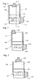
- Figure 1 shows a variable cam timing phaser in which the housing 104 is made of a first material and contains a circumferential notched groove or inset 114.
- the notched groove 114 is axially centered on the outer circumference of the housing 104 between the leading and trailing edges of the housing 104.
- the notched groove 114 receives driving element 108.
- the driving element 108 is made of a second material.
- the driving element 108 is used to accept drive and may be a gear if a timing gear is used or a sprocket if a timing chain or timing belt is used.
- the housing 104 surrounds the rotor 102, which provides a connection, in this case a mounting flange 110 to a camshaft 120 coaxially located within the housing 104.
- the rotor 102 is shown schematically and no details should be implied, including the shape of the spool 112 and the location of the spool.
- the first material is preferably aluminum, magnesium, another lightweight material, or plastic.
- the second material is preferably steel.
- the rotor 102 may also be made of the same first material as the housing 104. Cover plates 106 are present on either side of the housing 104.
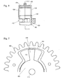
- Figure 6 shows a cross-section of Figure 1 and the relationship of the housing 104 relative to the rotor 102 to form the chamber 118 for receiving the vane 116 of rotor.
- Figure 6 also shows examples of an interlocking feature 122,124.
- the interlocking feature 122, 124 may be any radial feature that facilitates radial, axial, and rotational retention.
- the interlocking feature 122, 124 may extend from the driving element 108 into the housing 104 as shown by 122 or from the housing 104 to the driving element 108 as shown by 124.
- the shape of the interlocking feature 122, 124 is not limited to those shown in Figure 6.
- the interlocking feature 122,124 may be continuously present around the circumference of the housing 104 or may be spaced around the circumference of the housing 104 with one or more interlocking features 122,124 present.
- the interlocking features 122,124 shown in Figure 6 may be present in any of the embodiments of the present invention.
- Figure 2 shows a second embodiment in which the housing 204 is made of a first material and contains a circumferential notched groove or inset 214.
- the notched groove 214 is adjacent to either the leading end or the trailing edge of the housing 204.
- the notched groove 214 receives driving element 208.
- the driving element 208 is made of a second material.
- the driving element 208 is used to accept drive and may be a gear if a timing gear is used or a sprocket if a timing chain or timing belt is used.
- the housing 204 surrounds the rotor 202 which provides a connection, in this case a mounting flange 210, to a camshaft 220 coaxially located within the housing 204.
- the rotor 202 is shown schematically and no details should be implied, including the shape of the spool 212 and the location of the spool.
- the first material is preferably aluminum, magnesium, another lightweight material, or plastic.
- the second material is preferably steel.
- the rotor 202 may also be made of the same first material as the housing 204. Cover plates 206 are present on either side of the housing 204.
- Figure 3 shows another embodiment of the present invention in which the driving element 308 is centrally located around the circumference of the housing 304 between the leading and trailing edges of the housing.
- the housing 304 is made of a first material and the driving element 308 is made of a second material.
- the driving element 308 is used to accept drive and may be a gear if a timing gear is used or a sprocket if a timing chain or timing belt is used.
- the housing 304 surrounds the rotor 302, which provides a connection, in this case a mounting flange 310, to a camshaft 320 coaxially located within the housing 304.
- the rotor 302 is shown schematically and no details should be implied, including the shape of the spool 312 and the location of the spool.
- the first material is preferably aluminum, magnesium, another lightweight material, or plastic.
- the second material is preferably steel.
- the rotor 302 may also be made of the same material as the housing 304.
- Figure 4 shows a fourth embodiment in which the housing 404 is made of a first material and contains a circumferential notched groove or inset 414.
- the notched groove 414 is along the entire outer circumference width of the housing 404 extending between the leading and the trailing edges of the housing 404.
- the notched groove 414 receives the driving element 408.
- the driving element 408 is made of a second material.
- the driving element 408 is used to accept drive and may be a gear if a timing gear is used or a sprocket if a timing chain or timing belt is used.
- the housing 404 surrounds the rotor 402, which provides a connection, in this case a mounting flange 410, to a camshaft 420 coaxially located within the housing 404.
- the rotor 402 is shown schematically and no details should be implied, including the shape of the spool 412 and the location of the spool.
- the first material is preferably aluminum, magnesium, another lightweight material, or plastic.
- the second material is preferably steel.
- the rotor 402 may also be made of the same first material as the housing 404. Cover plates 406 are present on either side of the housing 404.
- Figure 5 shows a cross-section of Figure 4 and the relationship of the housing 404 relative to the rotor 402 to form the chamber 418 for receiving the vane 416 of the rotor 402.
Landscapes
- Engineering & Computer Science (AREA)
- Mechanical Engineering (AREA)
- General Engineering & Computer Science (AREA)
- Valve Device For Special Equipments (AREA)
Applications Claiming Priority (2)
| Application Number | Priority Date | Filing Date | Title |
|---|---|---|---|
| US50083903P | 2003-09-05 | 2003-09-05 | |
| US500839P | 2003-09-05 |
Publications (1)
| Publication Number | Publication Date |
|---|---|
| EP1512846A2 true EP1512846A2 (fr) | 2005-03-09 |
Family
ID=34135375
Family Applications (1)
| Application Number | Title | Priority Date | Filing Date |
|---|---|---|---|
| EP04255337A Withdrawn EP1512846A2 (fr) | 2003-09-05 | 2004-09-02 | Déphaseur d'arbre à cames avec un boítier et un élément d'entraínement formé de deux matériaux différents |
Country Status (3)
| Country | Link |
|---|---|
| US (1) | US20050051121A1 (fr) |
| EP (1) | EP1512846A2 (fr) |
| JP (1) | JP2005083384A (fr) |
Cited By (2)
| Publication number | Priority date | Publication date | Assignee | Title |
|---|---|---|---|---|
| DE102014214119A1 (de) * | 2014-07-21 | 2015-08-20 | Schaeffler Technologies AG & Co. KG | Nockenwellenversteller |
| DE102014221192A1 (de) * | 2014-10-20 | 2016-04-21 | Schaeffler Technologies AG & Co. KG | Nockenwellenversteller |
Families Citing this family (6)
| Publication number | Priority date | Publication date | Assignee | Title |
|---|---|---|---|---|
| DE102007056550A1 (de) * | 2007-11-23 | 2009-05-28 | Schaeffler Kg | Modular aufgebauter Nockenwellenversteller mit Ketten- oder Riemenrad |
| DE102007056549A1 (de) | 2007-11-23 | 2009-05-28 | Schaeffler Kg | Gekröpftes Ketten- oder Riemenrad für modular aufgebauten Nockenwellenversteller |
| US11193399B2 (en) | 2018-11-27 | 2021-12-07 | Borgwarner, Inc. | Variable camshaft timing assembly |
| US10954829B2 (en) | 2018-12-19 | 2021-03-23 | Borgwarner, Inc. | Oldham flexplate for concentric camshafts controlled by variable camshaft timing |
| US11280228B2 (en) | 2020-07-07 | 2022-03-22 | Borgwarner, Inc. | Variable camshaft timing assembly |
| US11852054B2 (en) | 2021-09-17 | 2023-12-26 | Borgwarner Inc. | Variable camshaft timing system |
Family Cites Families (6)
| Publication number | Priority date | Publication date | Assignee | Title |
|---|---|---|---|---|
| GB1204641A (en) * | 1969-04-08 | 1970-09-09 | Ford Motor Co | Transmission gears |
| US5333668A (en) * | 1991-12-09 | 1994-08-02 | Reynolds Metals Company | Process for creation of metallurgically bonded inserts cast-in-place in a cast aluminum article |
| US5588404A (en) * | 1994-12-12 | 1996-12-31 | General Motors Corporation | Variable cam phaser and method of assembly |
| JPH0989081A (ja) * | 1995-09-28 | 1997-03-31 | Fuji Heavy Ind Ltd | 汎用エンジンの射出成形ギヤ及びその製造方法 |
| DE19708661B4 (de) * | 1997-03-04 | 2005-06-16 | Ina-Schaeffler Kg | Vorrichtung zur Variierung der Ventilsteuerzeiten einer Brennkraftmaschine, insbesondere Nockenwellen-Verstelleinrichtung nach dem Flügelzellenprinzip |
| US6283076B1 (en) * | 2000-06-09 | 2001-09-04 | Borgwarner Inc. | Torsionally compliant sprocket for engine balance shaft drive and method of manufacture |
-
2004
- 2004-09-01 US US10/932,188 patent/US20050051121A1/en not_active Abandoned
- 2004-09-02 EP EP04255337A patent/EP1512846A2/fr not_active Withdrawn
- 2004-09-03 JP JP2004257053A patent/JP2005083384A/ja active Pending
Cited By (2)
| Publication number | Priority date | Publication date | Assignee | Title |
|---|---|---|---|---|
| DE102014214119A1 (de) * | 2014-07-21 | 2015-08-20 | Schaeffler Technologies AG & Co. KG | Nockenwellenversteller |
| DE102014221192A1 (de) * | 2014-10-20 | 2016-04-21 | Schaeffler Technologies AG & Co. KG | Nockenwellenversteller |
Also Published As
| Publication number | Publication date |
|---|---|
| US20050051121A1 (en) | 2005-03-10 |
| JP2005083384A (ja) | 2005-03-31 |
Similar Documents
| Publication | Publication Date | Title |
|---|---|---|
| CN1908384B (zh) | 具有降低泄漏的用于叶片型电动机的转子 | |
| US9255500B2 (en) | Valve timing control apparatus | |
| EP1512846A2 (fr) | Déphaseur d'arbre à cames avec un boítier et un élément d'entraínement formé de deux matériaux différents | |
| US9021680B2 (en) | Apparatus for the variable setting of the control times of gas exchange valves of an internal combustion engine | |
| CN101087933B (zh) | 用于内燃机的凸轮轴调节器 | |
| US9062573B2 (en) | Valve timing controller | |
| US20080022952A1 (en) | Valve timing control apparatus and its assembling method | |
| CN101087932B (zh) | 用于内燃机的凸轮轴调节器 | |
| CN102762820A (zh) | 用于可变调整内燃机换气气门的控制时间的设备的叶轮 | |
| US4763614A (en) | Composite camshaft for internal combustion engines and a method for its manufacture | |
| US8978607B2 (en) | Device for variably adjusting the control times of gas exchange valves of an internal combustion engine | |
| US9957852B2 (en) | Cushion ring assembly for a sprocket driven by a chain | |
| EP1513245B1 (fr) | Méthode de fabrication d'un générateur électrique pour un moteur à combustion interne | |
| US9353653B2 (en) | Valve timing adjusting apparatus | |
| JP2000240798A (ja) | シール構造 | |
| CN101160454B (zh) | 用于可变地调整内燃机换气阀控制时间的装置 | |
| US20180149044A1 (en) | Valve opening/closing timing control device | |
| US7779801B2 (en) | Camshaft adjuster for an internal combustion engine | |
| WO2017169694A1 (fr) | Arbre à cames pour moteur et son procédé de fabrication | |
| EP1617104A2 (fr) | Combination de poulie et de roue dentée de démarreur pour un moteur | |
| US20100242876A1 (en) | Modular construction camshaft adjuster with a chain or belt wheel | |
| CN115485471B (zh) | 用于内燃机的罩 | |
| US20190234249A1 (en) | Cam phaser and cam shaft arrangement with cam phaser | |
| JP7700645B2 (ja) | 内燃機関のチェーンケース | |
| US8418666B2 (en) | Multipiece camshaft assembly |
Legal Events
| Date | Code | Title | Description |
|---|---|---|---|
| PUAI | Public reference made under article 153(3) epc to a published international application that has entered the european phase |
Free format text: ORIGINAL CODE: 0009012 |
|
| AK | Designated contracting states |
Kind code of ref document: A2 Designated state(s): AT BE BG CH CY CZ DE DK EE ES FI FR GB GR HU IE IT LI LU MC NL PL PT RO SE SI SK TR |
|
| AX | Request for extension of the european patent |
Extension state: AL HR LT LV MK |
|
| RAP1 | Party data changed (applicant data changed or rights of an application transferred) |
Owner name: BORGWARNER INC. |
|
| STAA | Information on the status of an ep patent application or granted ep patent |
Free format text: STATUS: THE APPLICATION HAS BEEN WITHDRAWN |
|
| 18W | Application withdrawn |
Effective date: 20051209 |