EP1512549A1 - Binder and binding device - Google Patents
Binder and binding device Download PDFInfo
- Publication number
- EP1512549A1 EP1512549A1 EP03723213A EP03723213A EP1512549A1 EP 1512549 A1 EP1512549 A1 EP 1512549A1 EP 03723213 A EP03723213 A EP 03723213A EP 03723213 A EP03723213 A EP 03723213A EP 1512549 A1 EP1512549 A1 EP 1512549A1
- Authority
- EP
- European Patent Office
- Prior art keywords
- binder
- split ring
- ring part
- spine portion
- engaging
- Prior art date
- Legal status (The legal status is an assumption and is not a legal conclusion. Google has not performed a legal analysis and makes no representation as to the accuracy of the status listed.)
- Granted
Links
Images


Classifications
-
- B—PERFORMING OPERATIONS; TRANSPORTING
- B42—BOOKBINDING; ALBUMS; FILES; SPECIAL PRINTED MATTER
- B42F—SHEETS TEMPORARILY ATTACHED TOGETHER; FILING APPLIANCES; FILE CARDS; INDEXING
- B42F13/00—Filing appliances with means for engaging perforations or slots
- B42F13/16—Filing appliances with means for engaging perforations or slots with claws or rings
- B42F13/165—Filing appliances with means for engaging perforations or slots with claws or rings with flexible or resilient claws or rings
-
- B—PERFORMING OPERATIONS; TRANSPORTING
- B42—BOOKBINDING; ALBUMS; FILES; SPECIAL PRINTED MATTER
- B42F—SHEETS TEMPORARILY ATTACHED TOGETHER; FILING APPLIANCES; FILE CARDS; INDEXING
- B42F13/00—Filing appliances with means for engaging perforations or slots
- B42F13/16—Filing appliances with means for engaging perforations or slots with claws or rings
- B42F13/20—Filing appliances with means for engaging perforations or slots with claws or rings pivotable about an axis or axes parallel to binding edges
- B42F13/22—Filing appliances with means for engaging perforations or slots with claws or rings pivotable about an axis or axes parallel to binding edges in two sections engaging each other when closed
-
- B—PERFORMING OPERATIONS; TRANSPORTING
- B42—BOOKBINDING; ALBUMS; FILES; SPECIAL PRINTED MATTER
- B42B—PERMANENTLY ATTACHING TOGETHER SHEETS, QUIRES OR SIGNATURES OR PERMANENTLY ATTACHING OBJECTS THERETO
- B42B5/00—Permanently attaching together sheets, quires or signatures otherwise than by stitching
- B42B5/08—Permanently attaching together sheets, quires or signatures otherwise than by stitching by finger, claw or ring-like elements passing through the sheets, quires or signatures
- B42B5/10—Permanently attaching together sheets, quires or signatures otherwise than by stitching by finger, claw or ring-like elements passing through the sheets, quires or signatures the elements being of castellated or comb-like form
- B42B5/103—Devices for assembling the elements with the stack of sheets
-
- B—PERFORMING OPERATIONS; TRANSPORTING
- B42—BOOKBINDING; ALBUMS; FILES; SPECIAL PRINTED MATTER
- B42F—SHEETS TEMPORARILY ATTACHED TOGETHER; FILING APPLIANCES; FILE CARDS; INDEXING
- B42F13/00—Filing appliances with means for engaging perforations or slots
- B42F13/16—Filing appliances with means for engaging perforations or slots with claws or rings
-
- B—PERFORMING OPERATIONS; TRANSPORTING
- B42—BOOKBINDING; ALBUMS; FILES; SPECIAL PRINTED MATTER
- B42P—INDEXING SCHEME RELATING TO BOOKS, FILING APPLIANCES OR THE LIKE
- B42P2241/00—Parts, details or accessories for books or filing appliances
- B42P2241/24—Means for facilitating stacking or packaging
Definitions
- the present invention relates to a binder for binding sheets of loose-leaf paper and to a binding apparatus for automatically fitting the binder to the sheets of loose-leaf paper.
- a plastic binder for binding sheets of loose-leaf paper and documents perforated with multiple-hole paper punchers (refer to JP-A-2000-289376, for example) are known.
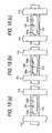
- FIGs. 20, 21 and 22 show a conventional binder 1 with a number of 1/2 ring parts 3 and 4 arranged at constant intervals on both side edges of spine portions 2, which are respectively formed into double-split hinges by monolithic molding.
- a projection 5 is formed at the tip of each 1/2 ring part 3 in the upper line and has a bulged tip, whereas a depression 6 corresponding in configuration to the bulged tip of the projection 5 is formed in the tip of each 1/2 ring part 4 in the lower line so that the upper and lower 1/2 ring parts 3 and 4 can be engaged together by press-fitting the projection 5 into the depression 6.
- the above conventional binder is in the form of a double-split ring and when the plurality of binders are stacked up, there is produced a gap between the binders as shown in Fig. 21(b) because of the difference between the inner and the outer diameters of the respective 1/2 ring parts 3 and 4.
- the drawback is that it is inconvenient to carry the binders as the binders may be dismembered while being handled and the binders are rendered bulky when they are packaged.
- the binding process is mechanized, moreover, a large amount of binders are necessarily charged into a binding machine and the conventional binder will necessitate a large storage space and this constitutes an obstacle to reducing the machine size. It is therefore still another object of the invention to provide a space-saving, easy-to-handle binder.
- the projection projected circumferentially from the tip of each 1/2 ring part on one side and the depression formed in the tip of each 1/2 ring part on the other are used for forming the engaging means for engaging the 1/2 ring parts. Therefore, use has to be made of a pattern drawing means such as rotary drawing for forming the projection in such a shape that its tip is bulged and the depression 6 in such a shape that its interior is also bulged symmetrically about the projection, so that the metal mold tends to become complicated in structure, thus increasing the production cost.
- the projection and the depression will have to be made to the suitable measurements so as to secure the engaging strength, which causes the tip portion of the ring part to necessarily grow thicker than the diameters of the projection and the depression, whereby it is difficult to form a slender ring part. It is therefore a further object to decrease the production cost of a binder as well as forming slender ring parts.
- the invention is proposed to accomplish the objects above by providing a binding apparatus for binding sheets of loose-leaf paper, using a binder that disposes split ring parts on both sides of a spine portion in parallel with each other, comprising: a paper table; a binder holding portion for holding both ends of the spine portion of the binder, conveying the binder from a source of a binder supply and setting the binder to face the back of the sheets of loose-leaf paper on the paper table; a hoisting stopper portion, for positioning the loose-leaf paper, that is positioned in front of the spine portion of the binder held by the binder holding portions and in the rear of the back of the sheets of loose-leaf paper on the paper table; a binding portion for closing and engaging the split ring parts of the binder by pushing the split ring parts from behind; and control means that sequentially control the binder holding portion, the stopper portion and the binding portion, wherein one-cycle work of fitting the binder to the sheets of loose-leaf paper is automatically conducted.
- the invention provides a binding apparatus, wherein a plurality of slits are formed with the same pitch as the ring pitch of the binder in the rear edge portion of the paper table so as to close and engage the ring parts of the binder through the holes of the sheets of loose-leaf paper and the slits.
- the invention provides a binding apparatus, wherein the binder holding portion comprises a pinch portion capable of opening and closing so as to clutch both ends of the spine portion of the binder by driving the pinch portions to open and close.
- the invention provides a binding apparatus, wherein the stopper portion comprises a plurality of stopper pins, arranged with integral multiple pitch of the ring pitch of the binder, that position the sheets of loose-leaf paper and support the spine portion of the binder.
- the invention provides a binding apparatus, wherein slits for preventing the interference of the stopper pins of the stopper portion at the time of advancing the binding portion are formed in the front edge portion of the binding portion for closing and engaging split ring parts of the binder by pushing the split ring parts from behind.
- the invention provides a binder having a spine portion; a number of split ring parts arranged at constant intervals on upper and lower edges on one side of the spine portion; and engaging means formed at both ends of each split ring part whereby to bind up sheets of loose-leaf paper by engaging both ends of each split ring part, the split ring parts being connected by upper and lower edges of the spine portion and a thin hinge.
- the invention provides a binder comprising: a spine portion; a number of split ring parts arranged at constant intervals on upper and lower edges on one side of the spine portion; and engaging means formed at both ends of each split ring part, whereby to bind sheets of loose-leaf paper by engaging both ends of each split ring part, wherein each split ring part comprises three members including an intermediate ring part and a pair of outer ring parts respectively coupled by a thin hinge to both ends of each intermediate ring, the spine portion is coupled with the intermediate ring part, and the pair of outer ring parts on both ends are capable of opening and engaging.
- the invention provides a binder comprising: a spine portion; split ring parts arranged at constant intervals on both side edges of the spine portion; and engaging means formed at both ends of the split ring part, whereby to bind sheets of loose-leaf paper by engaging both ends of each split ring part, wherein the spine portion is projected forward or backward, so that, when binders are stacked, the spine portion of one of the stacked binders is brought into contact with the spine portion of another of the stacked binders.
- the invention provides a binder comprising: a spine portion; split ring parts arranged at constant intervals on both side edges of the spine portion; and engaging means formed at both ends of the split ring part, whereby to bind sheets of loose-leaf paper by engaging both ends of each split ring part, wherein the outer and inner peripheral faces of the split ring part are formed to have the same curvature, so that, when binders are stacked, the back of one of the stacked binders is brought into contact with the front of another of the stacked binders.
- the invention provides a binder comprising: a spine portion; split ring parts arranged at constant intervals on both side edges of the spine portion; and engaging means formed at both ends of the split ring part, whereby to bind sheets of loose-leaf paper by engaging both ends of each split ring part, wherein each split ring part comprises three members including an intermediate ring part and a pair of outer ring parts respectively coupled by a thin hinge to both ends of each intermediate ring, and the outer and inner peripheral faces of at least the central split ring part having the same curvature, so that, when binders are stacked, the back of the central split ring part of one of the stacked binders is brought into contact with the front of the central split ring part of another of the stacked binders.
- the invention provides a binder wherein the respective tips of the three members of split ring parts are formed to trued up in a substantially straight line.
- the invention provides a binder comprising: a spine portion; split ring parts arranged at constant intervals on both side edges of the spine portion; and engaging means formed at both ends of the split ring part, whereby to bind sheets of loose-leaf paper by engaging both ends of each split ring part, wherein one or a plurality of depressions are formed on one of the front and the back of the spine portion, and one or plurality of projections are formed on the other of the front and the back of the spine portion so that the depressions and the projections are engaged mutually, whereby a plurality of binders can be coupled in a stacked condition.
- the invention provides a binder wherein the depression comprises a slit with long sideways including a pin hole portion for engageing with the projection and a broad slit portion continuous to the pin hole portion and having an outer diameter greater than that of the projection, and wherein the engagement between the pin hole portion and the projection can be released by sliding a pair of binders in an engaged condition relatively.
- the invention provides a binder wherein a joint region between the pin hole portion and the broad slit portion is made narrower than the outer diameter of the projection so that a click stop function for generating a resistance when the projection slidably moves from the pin hole portion to the broad slit portion is provided.
- the invention provides a binder comprising: a spine portion; split ring parts arranged at constant intervals on both side edges of the spine portion; and engaging means formed at both ends of the split ring part, whereby to bind sheets of loose-leaf paper by engaging both ends of each split ring part, wherein the engaging means comprises a scarf structure having radial, symmetrical steps at both ends of each split ring part, a hook portion formed at one end, and a catch portion formed at the other end for engaging with the hook portion.
- the invention provides a binder wherein the catch portion comprises a slot.
- the invention provides a binder comprising: a spine portion; split ring parts arranged at constant intervals on both side edges of the spine portion; and engaging means formed at both ends of the split ring part, whereby to bind sheets of loose-leaf paper by engaging both ends of each split ring part, wherein the engaging means comprise a scarf structure having radial, symmetrical steps at both ends of each split ring part, a hook portion formed on a surface side of the step of the split ring part on one side, and a catch portion formed on an undersurface side of the step of the split ring part on the other side for engaging with the hook portion.
- the invention provides a binder wherein the catch portion comprises a slot.
- Figs. 1(a) to (d) show a plastic binder 11 with a spine portion 12 in the form of a thin board.
- a number of 1/2 ring parts 13 and 14 are arranged at constant intervals on upper and lower edges on one side of the long rear side of the spine portion, and the spine portion 12 and the respective 1/2 ring parts 13 and 14 on both upper and lower sides are coupled together via thin hinge portions in order to form monolithically molded parts.
- the spine portion 12 is not in the form of a double-split hinge and this is because when the binder is bound not manually but mechanically, the hinge structure with the opening and closing spine portion makes it difficult to clutch and keep holding the spine portion from the time when the binder is set until the termination of the binding operation.
- Engaging means are provided at the tips of the 1/2 ring parts 13 in the upper line and also at the tips of the 1/2 ring parts 14 in the lower line.
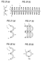
- Figs. 2 (a) and (b) show a plastic binder 21 according to another embodiment of the invention, wherein each ring is divided into three 120° 1/3 ring parts 22, 23, 24 that are coupled together and an intermediate 1/3 ring part 23 is formed integrally with a spine portion 25.
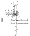
- Figs. 3(a) and (b) show a binder 31 according to still another embodiment of the invention, wherein each ring is divided into three parts: namely, a 180° ring part 32 and 90° ring parts 33 and 34 that are respectively coupled to the upper and lower 180° ring parts, and the intermediate 180° ring part 32 is formed integrally with a spine portion 35.
- the binders 11, 21 and 31 are formed such that their spine portions are projected outside from both the rightmost and leftmost ring parts, so that the binders can be held by clutching both ends of the spine portions 12, 25 and 35.
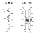
- a binder 111 according to a further embodiment of the invention, in which the binder is formed of resin by injection molding with ring parts arranged at constant intervals on a spine portion 112 corresponding in length to standard-size paper.
- each ring is divided into three parts including a central 1/3 ring part 113, and upper- and lower- side 1/3 ring parts 114 and 115 coupled to the central 1/3 ring part 113 and the ring is formed by bending, and engaging the tips of, the upper- and lower-side 1/3 ring parts 114 and 115.
- the curvature of the outer peripheral face of the central 1/3 ring part 113 is set equal to that of the inner peripheral face thereof and both edges of the respective 1/3 ring parts 113, 114 and 115 are trued up in a substantially straight line, whereby the central 1/3 ring parts 113 in front and in the rear make surface-to-surface contact with each other without leaving space therebetween when a plurality of binders 111 are stacked up as shown in Fig. 14.
- this arrangement has the effect of taking up little space when the binders as a whole are packaged and when a binding machine is charged with such binders since the upper- and lower- side 1/3 ring parts 114 and 115 are thinner than the central 1/3 ring part 113.
- a feed mechanism for successively conveying a plurality of binders forward is required.
- the central 1/3 ring parts 113 of the binder 111 in front and in the rear adhere fast to each other and leave no space therebetween, there is no possibility that the binder is hindered from being fed by the push load of the feed mechanism as the binder warps, so that mechanization of the binding process can be dealt with.
- the binder 111 in front and in the rear need not always make surface-to-surface contact with each other by equalizing the curvatures of the outer and inner peripheral faces of the central 1/3 ring part 113.
- the same effect as what is obtained from the preceding example is also achievable by arranging the binder 131 in front and in the rear such that they make contact with each other at three points including the spine portion 132, and both upper and lower ends of each central 1/3 ring part 133.
- circumferential slots 116 are formed in the inner peripheral faces of the three respective 1/3 ring parts and a hook portion 117 is provided at the tip of the upper-side 1/3 ring part 114, whereas a catch portion 118 engaging with the hook portion 117 is formed at the tip of the lower-side 1/3 ring part 115.
- a tip of the upper-side 1/3 ring part 114 in scarf joint structure in which the outer peripheral tip portion is cut out in a stepped form and the wedge-shaped planar hook portion 117 formed on a one-step lower step portion 119 is projected forward.
- a tip of the lower-side 1/3 ring part 115 in the scarf joint structure corresponding to the upper-side 1/3 ring part 114 in which structure the inner peripheral tip portion is cut out to form a step portion 120 as well as the wedge-shaped catch portion 118 corresponding to the hook portion 117 on the outer peripheral side.
- a circumferential slot 122 for receiving the hook portion 117 by subjecting the catch portion 118 to elastic deformation at the time of inserting the hook portion is formed in the inner base 121 of the catch portion 118.
- Figs. 18(a) and (b) show a ring formed by engaging the hook portion 117 of the upper-side 1/3 ring part 114 with the catch portion 118 of the lower-side 1/3 ring part 115.
- the upper-side 1/3 ring part 114 and the lower-side 1/3 ring part 115 are prevented from slipping out of place in circumferential and lateral directions as the hook portion 117 and the catch portion 118 are engaged together in the scarf joint structure at the tips of the upper-side 1/3 ring part 114 and the lower-side 1/3 ring part 115, both the 1/3 ring parts 114 and 115 are so fixed as to be prevented from mutually slipping out in the radial direction.
- the upper-side 1/3 ring part 114 will never shift to and from the lower-side 1/3 ring part 115 in case where external force is applied to the upper-side 1/3 ring part 114 in the direction of the center of the ring or where external force is applied to the lower-side 1/3 ring part 115 in the direction outside the ring.
- step portion 120 of the lower-side 1/3 ring part 115 is mounted on the step portion 119 of the upper-side 1/3 ring part 114, moreover, the upper-side 1/3 ring part 114 will never shift to and from the lower-side 1/3 ring part 115 in case where external force is applied to the upper-side 1/3 ring part 114 in the direction outside the ring or where external force is applied to the lower-side 1/3 ring part 115 in the direction of the center of the ring.
- the catch portions 118 are opened laterally by pulling the upper-side 1/3 ring parts 114 and lower-side 1/3 ring parts 115 laterally in the circumferential direction so as to release the engaging of the catch portions 118 with the hook portions 117; the binder 111 thus removed are naturally reusable accordingly.
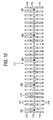
- pins 124 projecting toward the centers of the respective rings are formed at constant intervals on the inner surface side of the spine portion 112 (five pins according to this embodiment of the invention), and slits 125 and 126 making a engaging pair with the pins 124 are formed on the back side of the spine portion 112. Therefore, the pins 124 are fitted into the slits 125 and 126 of the binder 111 in the front row when the plurality of binders 111 are stacked up as shown in Fig. 14, whereby the plurality of binders 111 are coupled together and as the plurality of binders 111 are prevented from coming apart, the binders 111 become easy to handle when the binders are unpacked and when the binding machine is charged with the binders.
- Figs. 19 (a) to (c) show the slits 125 and 126 in detail: Fig. 19(a) shows the central slit 125 in Fig. 10; and Fig. 19(b), the four slits 126 other than the central one, each being shown in four lateral places.
- the slits 125 and 126 are laterally oblong in configuration and when the plurality of binders 111 are stacked up by truing up both edges of the boards, the pins 124 of the binders 111 in the back row face the left end portions of the slits 125 and 126 in the front row.
- the left ends of the slits 125 and 126 are pin hole portions 125a and 126a having the same width as the diameter of the pin 124 or a width slightly narrower than the diameter thereof and the width of any portion other than the pin hole portions 125a and 126a is set greater than the diameter of the pin 124.
- the slit 126 shown in Fig. 19(b) is formed with the pin hole portion 126a and a right-side broad slit portion 126b to form a linear slit
- the width of the joint region of the central slit 125 shown in Fig. 19(a) formed with the pin hole portion 125a and the broad slit portion 125b is narrow. Consequently, a click stop function for holding the pin 124 within the pin hole portion 125a is provided, so that the plurality of binders 111 coupled together are prevented from sliding because of vibration.
- any slit 126 other than the central slit 125 may be in the click stop form as shown in Fig. 19(a) but the binders 111 can simply be separated without applying force for sliding purposes on condition that any slit 126 other than the central slit 125 is formed so that the pin 124 is easily slidable as in the case of the example above.
- a slit 127 shown in Fig. 19(c) refers to a modified example of the slit 126 shown in Fig. 19(b) and is formed with a pin hole portion 127a as a parallel linear slit that is long sideways and is continuous in configuration to the broad slit portion 127.
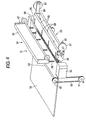
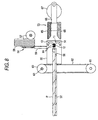
- FIGs. 4 and 5 show a binding apparatus 51 having a paper table 52.
- a binding portion 53 for closing plastic binders by moving forward is provided in the rear of the paper table 52 (right-hand side of Fig. 4) and a stopper portion 54 for positioning paper and the binder is disposed above the binding portion 53.
- binder holding portions 55 are disposed slightly ahead of the stopper portion 54 and on both the respective right and left of the paper table 52.
- slits 56 are cut as if forming teeth of a comb at constant intervals in the rear edge portion of the paper table 52 and a slit-to-slit space conforms to a space between punched holes of loose-leaf paper.
- the stopper portion 54 is fitted with stopper pins 59 like square bars at constant intervals on the front of a plate 58 to be moved upward and downward by a rack and pinion mechanism 57.
- the stopper pins 59 are suspended downward from the plate 58 and when the stopper portion 54 is moved down, the lower end of each stopper pin 59 is located lower than the paper table 52 but when the stopper portion 54 is moved upward, the stopper pins 59 retreat upward the paper table 52.
- Each of the binder holding portions 55 is latched on a belt 62 stretched between two upper and lower pulleys 60 and 61, and the upper right and left pulleys 60 are coupled by a synchronous shaft 63, whereupon the right and left binder holding portions 55 are moved upward and downward synchronously by driving the lower pulleys 61 by motors (not shown).
- Open-and-close pinch portions 64 are provided on the sides opposite to the respective binding holding portions 55, which clutch both ends of the spine portion of the binder by opening and closing the pinch portions 64, using driving means such as solenoids.
- the binding portion 53 has a pair of horizontal plates 65 vertically disposed in parallel to each other and inner opposed sides of the front end portions of the plates 65 are inclined to form a V-shaped opening in cross section as shown in Fig. 5.
- the binding portion 53 is coupled to crank plates 67 via links 66 and longitudinally reciprocates in response to the movement of the crank plates 67 driven to rotate by motors (not shown) .
- vertically long slits 68 corresponding to the stopper pins 59 of the stopper portion 54 are formed in the front of the pair of vertical plates 65 forming the binding portion 53, so that the binding portion 53 is allowed to advance in the direction of the paper table 52 without interfering the stopper pins 59.
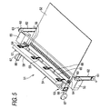
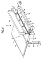
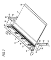
- the right and left binder holding portions 55 move downward into a binder stoker (not shown) under the paper table 52 to put each end of the spine portion of the binder in between the pinch portions 64 by opening the pinch portions 64 and then move upward after holding the binder by closing the pinch portions 64, so that the binder 11 is set to face the rear edge of the paper table 52 as shown in Fig. 6 to Fig. 8.
- the stopper portion 54 moves downward, whereupon the stopper pins 59 are inserted into the slits 56 of the paper table 52, and the stopper portion 54 assumes a standby condition so as to wait for paper setting.
- the binding portion 53 is retreated and the stopper portion 54 moves upward whereby to make the stopper pins 59 retreat from the front of the spine portion 12 of the binder 11.
- the loose-leaf paper P in a bound condition is ready for being taken out of the paper table 52 and the binder holding portions 55 move downward to the binder stoker (not shown), return to the standby condition after clutching next binder 11 and complete one-cycle operation.
- an arrangement may be made so that a start switch is automatically started to perform the one-cycle operation after sheets of paper are set on the paper table by mounting a paper detection sensor to the paper table instead of manually operating the start switch to perform the one-cycle operation.
- a paper feed mechanism for pulling sheets of paper into the paper table may be provided so as to perform a series of operations including binding sheets of paper up to discharging the paper or a binding apparatus may be mounted in a composite machine having a copying machine, a multiple-hole paper puncher and so on in combination in order to perform copying, punching and binding processes collectively.
- the binder can be fitted to sheets of loose-leaf paper by the binding apparatus of the invention without relying on manual work and hence the process of binding up documents is performed very quickly, which has the effect of not only promoting labor saving but improving efficiency of processing paperwork.
- the binder according to the invention is different from the conventional ones in that the former is so structured that the spine portion itself is not designed to open and close and it is ensured that the binder is held by the binding apparatus intended to perform the operation of holding and closing the binder. Accordingly, the invention makes it possible to put this binding system to practical use.
- the binders are by far easier to handle when carried or loaded into the binding machine, so that space efficiency is improved when the binders are packed into a packaging box or the binding machine.
- spine portions of the binders thus stacked up are kept in contact with each other, whereupon the binders are prevented from being bent even though the push load is applied by the feed mechanism of the binding machine to the spine portion.
- the binder is provided with the engaging means such as pins and slits, the binders in a stacked-up condition are not separated and become by far easier to handle when carried or loaded into the binding machine. Since it has been arranged that the stacked-up binders are released from engaging together by mutually sliding them, a binder separating mechanism simple in construction can be devised when it is attempted to mechanize the binding process. Therefore, the invention can contribute to simplifying the structure of such a mechanism.
- a linear slide mold may be used to form the binder, so that the molding cost is considerably decreased in comparison with the rotary drawing metal mold required for the conventional binder.
- the ring part of the binder can be made thinner than that of the conventional binder whose ring engaging means is formed with a tip expansion type pin and a hole corresponding in configuration to the tip, whereby the number of sheets of paper to be bound up can be increased.
- the possibility that the engaging of the split ring parts may be broken by the radial external force is obviated by forming the hook portion on the surface side of the front step portion of the split ring part on one side and the catch portion on the undersurface side of the step portion of the split ring part on the other.
- the formation of the slotted catch portion results in preventing the engaging strength from lowering even though the catch portion is attached to and removed from the hook portion over repeatedly, so that the binder can also be used repeatedly.
Landscapes
- Engineering & Computer Science (AREA)
- Textile Engineering (AREA)
- Sheet Holders (AREA)
Abstract
Description
Claims (18)
- A binding apparatus for binding sheets of loose-leaf paper, using binder that disposes split ring parts on both sides of a spine portion in parallel with each other, comprising:wherein one-cycle work of fitting the binder to the sheets of loose-leaf paper is automatically conducted.a paper table;a binder holding portion for holding both ends of the spine portion of the binder, conveying the binder from a source of binder supply and setting the binder to face the back of the sheets of loose-leaf paper on the paper table;a hoisting stopper portion, for positioning the loose-leaf paper, that is positioned in front of the spine portion of the binder held by the binder holding portions and in the rear of the back of the sheets of loose-leaf paper on the paper table;a binding portion for closing and engaging the split ring parts of the binder by pushing the split ring parts from behind; andcontrol means that sequentially controlling the binder holding portion, the stopper portion and the binding portion,
- The binding apparatus according to claim 1, wherein a plurality of slits are formed with the same pitch as the ring pitch of the binder in the rear edge portion of the paper table so as to close and engage the ring parts of the binder through the holes of the sheets of loose-leaf paper and the slits.
- The binding apparatus according to claim 1, wherein the binder holding portion comprises a pinch portion capable of opening and closing so as to clutch both ends of the spine portion of the binder by driving the pinch portions to open and close.
- The binding apparatus according to claim 1, wherein the stopper portion comprises a plurality of stopper pins, arranged with integral multiple pitch of the ring pitch of the binder, that position the sheets of loose-leaf paper and support the spine portion of the binder.
- The binding apparatus according to claim 4, wherein slits for preventing the interference of the stopper pins of the stopper portion at the time of advancing the binding portion are formed in the front edge portion of the binding portion for closing and engaging split ring parts of the binder by pushing the split ring parts from behind.
- A binder having a spine portion;a number of split ring parts arranged at constant intervals on upper and lower edges on one side of the spine portion; andengaging means formed at both ends of each split ring part whereby to bind up sheets of loose-leaf paper by engaging both ends of each split ring part,the split ring parts being connected by upper and lower edges of the spine portion and a thin hinge.
- A binder comprising:wherein each split ring part comprises three members including an intermediate ring part and a pair of outer ring parts respectively coupled by a thin hinge to both ends of each intermediate ring,a spine portion;a number of split ring parts arranged at constant intervals on upper and lower edges on one side of the spine portion; andengaging means formed at both ends of each split ring part, whereby to bind sheets of loose-leaf paper by engaging both ends of each split ring part,
the spine portion is coupled with the intermediate ring part, and
the pair of outer ring parts on both ends are capable of opening and engaging. - A binder comprising:wherein the spine portion is projected forward or backward, so that, when binders are stacked, the spine portion of one of stacked binders is brought into contact with the spine portion of the other of stacked binders.a spine portion;split ring parts arranged at constant intervals on both side edges of the spine portion; andengaging means formed at both ends of the split ring part, whereby to bind sheets of loose-leaf paper by engaging both ends of each split ring part,
- A binder comprising:wherein the outer and inner peripheral faces of the split ring part are formed to have the same curvature, so that, when binders are stacked, the back of one of stacked binders is brought into contact with the front of the other of stacked binders.a spine portion;split ring parts arranged at constant intervals on both side edges of the spine portion; andengaging means formed at both ends of the split ring part, whereby to bind sheets of loose-leaf paper by engaging both ends of each split ring part,
- A binder comprising:wherein each split ring part comprises three members including an intermediate ring part and a pair of outer ring parts respectively coupled by a thin hinge to both ends of each intermediate ring, anda spine portion;split ring parts arranged at constant intervals on both side edges of the spine portion; andengaging means formed at both ends of the split ring part, whereby to bind sheets of loose-leaf paper by engaging both ends of each split ring part,
the outer and inner peripheral faces of at least the central split ring part having the same curvature, so that, when binders are stacked, the back of the central split ring part of one of stacked binders is brought into contact with the front of the central split ring part of the other of stacked binders. - The binder according to claim 10, wherein the respective tips of the three members of split ring parts are formed to trued up in a substantially straight line.
- A binder comprising:wherein one or a plurality of depressions are formed on one of the front and the back of the spine portion, and one or plurality of projections are formed on the other of the front and the back of the spine portion so that the depressions and the projections are engaged mutually, whereby a plurality of binders can be coupled in a stacked condition.a spine portion;split ring parts arranged at constant intervals on both side edges of the spine portion; andengaging means formed at both ends of the split ring part, whereby to bind sheets of loose-leaf paper by engaging both ends of each split ring part,
- The binder according to claim 12, wherein the depression comprises a slit with long sideways including a pin hole portion for engageing with the projection and a broad slit portion continuous to the pin hole portion and having an outer diameter greater than that of the projection, and
wherein the engagement between the pin hole portion and the projection can be released by sliding a pair of binders in an engaged condition relatively. - The binder according to claim 13, wherein a joint region between the pin hole portion and the broad slit portion is made narrower than the outer diameter of the projection so that a click stop function for generating a resistance when the projection slidably moves from the pin hole portion to the broad slit portion is provided.
- A binder comprising:wherein the engaging means comprises:a spine portion;split ring parts arranged at constant intervals on both side edges of the spine portion; andengaging means formed at both ends of the split ring part, whereby to bind sheets of loose-leaf paper by engaging both ends of each split ring part,a scarf structure having radial, symmetrical steps at both ends of each split ring part;a hook portion formed at one end; anda catch portion formed at the other end for engaging with the hook portion.
- The binder according to claim 15, wherein the catch portion comprises a slot.
- A binder comprising:wherein the engaging means comprise:a spine portion;split ring parts arranged at constant intervals on both side edges of the spine portion; andengaging means formed at both ends of the split ring parts, whereby to bind sheets of loose-leaf paper by engaging both ends of each split ring part,a scarf structure having radial, symmetrical steps at both ends of each split ring part;a hook portion formed on a surface side of the step of the split ring part on one side; anda catch portion formed on an undersurface side of the step of the split ring part on the other side for engaging with the hook portion.
- The binder according to claim 17, wherein the catch portion comprises a slot.
Applications Claiming Priority (5)
| Application Number | Priority Date | Filing Date | Title |
|---|---|---|---|
| JP2002129236 | 2002-04-30 | ||
| JP2002129236A JP4300748B2 (en) | 2002-04-30 | 2002-04-30 | binder |
| JP2003029302 | 2003-02-06 | ||
| JP2003029302A JP4300813B2 (en) | 2003-02-06 | 2003-02-06 | binder |
| PCT/JP2003/005378 WO2003093025A1 (en) | 2002-04-30 | 2003-04-25 | Binder and binding device |
Publications (3)
| Publication Number | Publication Date |
|---|---|
| EP1512549A1 true EP1512549A1 (en) | 2005-03-09 |
| EP1512549A4 EP1512549A4 (en) | 2005-06-29 |
| EP1512549B1 EP1512549B1 (en) | 2011-06-29 |
Family
ID=29405304
Family Applications (1)
| Application Number | Title | Priority Date | Filing Date |
|---|---|---|---|
| EP03723213A Expired - Lifetime EP1512549B1 (en) | 2002-04-30 | 2003-04-25 | Binder and binding device |
Country Status (6)
| Country | Link |
|---|---|
| US (1) | US7665925B2 (en) |
| EP (1) | EP1512549B1 (en) |
| KR (2) | KR100853324B1 (en) |
| CN (2) | CN100558565C (en) |
| AU (1) | AU2003235857A1 (en) |
| WO (1) | WO2003093025A1 (en) |
Cited By (3)
| Publication number | Priority date | Publication date | Assignee | Title |
|---|---|---|---|---|
| WO2007013509A1 (en) | 2005-07-26 | 2007-02-01 | Max Co., Ltd. | Binder |
| GB2454910A (en) * | 2007-11-22 | 2009-05-27 | Acco Uk Ltd | A document binding machine |
| EP2765008A4 (en) * | 2012-11-28 | 2015-03-11 | Song Yanwei | Push ring device and coil bonding machine |
Families Citing this family (12)
| Publication number | Priority date | Publication date | Assignee | Title |
|---|---|---|---|---|
| US20040018041A1 (en) * | 2001-11-20 | 2004-01-29 | Samuel Amdahl | Plurality of binding elements for automated processes |
| US7661918B2 (en) * | 2003-05-30 | 2010-02-16 | General Binding Corporation | Binding machine and method |
| US7077595B2 (en) * | 2003-07-25 | 2006-07-18 | General Binding Corporation | Spine binder |
| JP4103725B2 (en) * | 2003-08-12 | 2008-06-18 | マックス株式会社 | Binding processing method, binding processing apparatus, and binder cartridge |
| CN100486819C (en) * | 2004-01-29 | 2009-05-13 | 美克司株式会社 | Bookbinding apparatus |
| JP4635767B2 (en) * | 2005-07-26 | 2011-02-23 | マックス株式会社 | binder |
| JP5145795B2 (en) * | 2006-07-24 | 2013-02-20 | 新日鐵住金株式会社 | Method for producing pearlitic rails with excellent wear resistance and ductility |
| KR200440215Y1 (en) * | 2007-11-12 | 2008-05-30 | 박정우 | Ring binder |
| DE102011018509A1 (en) * | 2011-04-23 | 2012-10-25 | Kolbus Gmbh & Co. Kg | Device for feeding book blocks to a bookbinding machine |
| JP6287532B2 (en) * | 2014-04-21 | 2018-03-07 | マックス株式会社 | Binding parts |
| CN108146097A (en) * | 2018-02-01 | 2018-06-12 | 兰州理工大学 | Loose-leaf device and method for stitching |
| CN112455119A (en) * | 2020-12-21 | 2021-03-09 | 符传若 | Magnetic suction type clamping structure of loose-leaf binder |
Family Cites Families (34)
| Publication number | Priority date | Publication date | Assignee | Title |
|---|---|---|---|---|
| US2337997A (en) * | 1939-03-07 | 1943-12-28 | Hiromi Tetsutaro | Method of making piston rings |
| US3613878A (en) * | 1969-08-29 | 1971-10-19 | Hartco Co | U-clip assembly |
| JPS5484162A (en) | 1977-12-15 | 1979-07-04 | Idec Izumi Corp | Electric device mounting apparatus |
| DE8014522U1 (en) | 1980-05-30 | 1980-09-04 | Renz, Peter, 7072 Heubach | Device for binding perforated sheets |
| DE3113835C2 (en) | 1981-04-06 | 1983-01-05 | Pfaff Industriemaschinen Gmbh, 6750 Kaiserslautern | Device for dropping skins |
| JPS57199695A (en) | 1981-06-02 | 1982-12-07 | Tadao Uno | Method of binding leaflet with binding hole to cover with binder |
| JPS61138564A (en) | 1984-12-10 | 1986-06-26 | Murata Mfg Co Ltd | Curing method of sheathing material for electron parts |
| US4607970A (en) * | 1985-02-05 | 1986-08-26 | Ted Scudder | Binder for perforated sheets |
| JPH0210074A (en) | 1988-06-28 | 1990-01-12 | Matsushita Refrig Co Ltd | Ice making apparatus for refrigerator and the like |
| US4900211A (en) | 1989-05-03 | 1990-02-13 | General Binding Corporation | Apparatus for binding materials using a curled-finger ring-type binder |
| JP2844085B2 (en) | 1989-07-20 | 1999-01-06 | セイコーインスツルメンツ株式会社 | Circuit board and method of mounting semiconductor element |
| JPH0627872Y2 (en) | 1989-10-03 | 1994-07-27 | 株式会社ショーワ | Backlash prevention mechanism in power transmission device |
| JP3055955B2 (en) | 1991-02-18 | 2000-06-26 | 三菱樹脂株式会社 | Manufacturing method of fiber reinforced plastic fan |
| JPH05162478A (en) | 1991-08-30 | 1993-06-29 | General Binding Corp | Automatic binding apparatus using inserting tool |
| US5618122A (en) * | 1993-02-04 | 1997-04-08 | C-Lock, Inc. | Molded plastic one-piece loose-leaf binder ring structure |
| JPH06312589A (en) | 1993-04-28 | 1994-11-08 | Canon Aptecs Kk | Automatic sheet material binding machine |
| JPH07208424A (en) | 1994-01-27 | 1995-08-11 | Nifco Inc | Board material connecting tool |
| JP3163489B2 (en) | 1994-07-22 | 2001-05-08 | カール事務器株式会社 | Jig for integrated ring punch with hole punch |
| JPH08135632A (en) | 1994-09-12 | 1996-05-31 | Nifco Inc | Member installing tool |
| JPH09240184A (en) | 1996-03-06 | 1997-09-16 | Kiyoueishiya:Kk | Document binder |
| JP3042732U (en) | 1997-04-21 | 1997-10-31 | 靖夫 青木 | Binding |
| GB9712718D0 (en) * | 1997-06-18 | 1997-08-20 | Heights Design Production Ltd | Binding apparatus |
| AU737904B2 (en) * | 1997-12-30 | 2001-09-06 | Attalus High Tech Industry Sa | Binding apparatus for paper piles |
| CH692495A5 (en) * | 1998-02-05 | 2002-07-15 | Gen Binding Corp | A ring binder mechanism. |
| JP2000289376A (en) | 1999-03-31 | 2000-10-17 | Ibico Trading Gmbh | Binder for fixing back part |
| JP4378581B2 (en) | 1999-11-02 | 2009-12-09 | カール事務器株式会社 | Paper binding device |
| JP2002192872A (en) * | 2000-10-19 | 2002-07-10 | Tomoda Giken Kogyo Kk | Filing implement |
| JP2002129236A (en) | 2000-10-24 | 2002-05-09 | Nippon Steel Corp | Stable production method of unidirectional electrical steel sheet |
| JP3383650B2 (en) * | 2001-03-23 | 2003-03-04 | 克己 金田 | Loose leaf bindings |
| JP2003029302A (en) | 2001-07-18 | 2003-01-29 | Sony Corp | Light control device and imaging device |
| US20040018041A1 (en) * | 2001-11-20 | 2004-01-29 | Samuel Amdahl | Plurality of binding elements for automated processes |
| US20030031502A1 (en) * | 2002-08-30 | 2003-02-13 | Rothschild Wayne H. | Binding element stacking structure |
| US7077595B2 (en) * | 2003-07-25 | 2006-07-18 | General Binding Corporation | Spine binder |
| USD508947S1 (en) * | 2004-02-23 | 2005-08-30 | Max Co., Ltd. | Set of ring binders |
-
2003
- 2003-04-25 AU AU2003235857A patent/AU2003235857A1/en not_active Abandoned
- 2003-04-25 EP EP03723213A patent/EP1512549B1/en not_active Expired - Lifetime
- 2003-04-25 WO PCT/JP2003/005378 patent/WO2003093025A1/en not_active Ceased
- 2003-04-25 KR KR1020047017273A patent/KR100853324B1/en not_active Expired - Fee Related
- 2003-04-25 US US10/512,681 patent/US7665925B2/en not_active Expired - Lifetime
- 2003-04-25 CN CNB038097168A patent/CN100558565C/en not_active Expired - Fee Related
- 2003-04-25 CN CN201210018005.8A patent/CN102514417B/en not_active Expired - Fee Related
-
2008
- 2008-01-14 KR KR1020080003777A patent/KR100914789B1/en not_active Expired - Fee Related
Cited By (7)
| Publication number | Priority date | Publication date | Assignee | Title |
|---|---|---|---|---|
| WO2007013509A1 (en) | 2005-07-26 | 2007-02-01 | Max Co., Ltd. | Binder |
| EP1908601A4 (en) * | 2005-07-26 | 2008-09-17 | Max Co Ltd | BINDING DEVICE |
| CN101513806B (en) * | 2005-07-26 | 2010-12-01 | 美克司株式会社 | Binder |
| US8568052B2 (en) | 2005-07-26 | 2013-10-29 | Max Co., Ltd. | Binder |
| GB2454910A (en) * | 2007-11-22 | 2009-05-27 | Acco Uk Ltd | A document binding machine |
| EP2062739A1 (en) * | 2007-11-22 | 2009-05-27 | Acco UK Limited | A document binding machine |
| EP2765008A4 (en) * | 2012-11-28 | 2015-03-11 | Song Yanwei | Push ring device and coil bonding machine |
Also Published As
| Publication number | Publication date |
|---|---|
| AU2003235857A1 (en) | 2003-11-17 |
| KR100914789B1 (en) | 2009-09-02 |
| KR20040107510A (en) | 2004-12-20 |
| US20050175434A1 (en) | 2005-08-11 |
| CN100558565C (en) | 2009-11-11 |
| EP1512549B1 (en) | 2011-06-29 |
| CN102514417A (en) | 2012-06-27 |
| EP1512549A4 (en) | 2005-06-29 |
| KR20080013008A (en) | 2008-02-12 |
| US7665925B2 (en) | 2010-02-23 |
| WO2003093025A1 (en) | 2003-11-13 |
| KR100853324B1 (en) | 2008-08-21 |
| CN102514417B (en) | 2014-06-04 |
| CN1649749A (en) | 2005-08-03 |
Similar Documents
| Publication | Publication Date | Title |
|---|---|---|
| US7665925B2 (en) | Binder and binding device | |
| US7726928B2 (en) | Binding processing apparatus | |
| KR940005910B1 (en) | How to bind and booklet | |
| US7901172B2 (en) | Bind processing method, bind processing device and binder cartridge | |
| KR101465065B1 (en) | Punching apparatus for spring note | |
| US5683218A (en) | Jig for perforating paper sheets and binding those on a ring binder | |
| WO2007013509A1 (en) | Binder | |
| JP4300748B2 (en) | binder | |
| JPS62259798A (en) | Method and device for separating available piece pile mutually involved and arranged to strip-shaped material | |
| US3407105A (en) | Heat sealed binding | |
| CN101263011B (en) | paper handling device | |
| US20040240967A1 (en) | Binding elements for binding a wide range of thicknesses of stacks of sheets | |
| KR200402190Y1 (en) | Auto fixing-device of twin ring | |
| JPH0521433Y2 (en) | ||
| JP4872661B2 (en) | Paper processing device | |
| RU45676U1 (en) | BROCHURE DEVICE | |
| JP2009113919A (en) | Paper processing device | |
| JP4872662B2 (en) | Paper processing device | |
| CN113696264A (en) | Financial bill punching machine and punching method | |
| MX2008001343A (en) | Binder | |
| KR20020054335A (en) | Apparatus for punching and closing a wire comb to bind sheets | |
| JPH07329474A (en) | Document retainer for binding implement | |
| DE1030231B (en) | Uninterrupted automatic machine for the permanent curling of the outer ends of firewood booklet cases with snap lock | |
| TW201434602A (en) | Full automatic book punching machine |
Legal Events
| Date | Code | Title | Description |
|---|---|---|---|
| PUAI | Public reference made under article 153(3) epc to a published international application that has entered the european phase |
Free format text: ORIGINAL CODE: 0009012 |
|
| 17P | Request for examination filed |
Effective date: 20041006 |
|
| AK | Designated contracting states |
Kind code of ref document: A1 Designated state(s): AT BE BG CH CY CZ DE DK EE ES FI FR GB GR HU IE IT LI LU MC NL PT RO SE SI SK TR |
|
| AX | Request for extension of the european patent |
Extension state: AL LT LV MK |
|
| A4 | Supplementary search report drawn up and despatched |
Effective date: 20050517 |
|
| RIC1 | Information provided on ipc code assigned before grant |
Ipc: 7B 42F 13/22 A Ipc: 7B 42F 13/16 B |
|
| 17Q | First examination report despatched |
Effective date: 20100205 |
|
| GRAP | Despatch of communication of intention to grant a patent |
Free format text: ORIGINAL CODE: EPIDOSNIGR1 |
|
| GRAS | Grant fee paid |
Free format text: ORIGINAL CODE: EPIDOSNIGR3 |
|
| GRAA | (expected) grant |
Free format text: ORIGINAL CODE: 0009210 |
|
| AK | Designated contracting states |
Kind code of ref document: B1 Designated state(s): DE FR GB NL SE |
|
| REG | Reference to a national code |
Ref country code: GB Ref legal event code: FG4D |
|
| REG | Reference to a national code |
Ref country code: DE Ref legal event code: R096 Ref document number: 60337549 Country of ref document: DE Effective date: 20110825 |
|
| REG | Reference to a national code |
Ref country code: NL Ref legal event code: T3 |
|
| REG | Reference to a national code |
Ref country code: SE Ref legal event code: TRGR |
|
| PLBE | No opposition filed within time limit |
Free format text: ORIGINAL CODE: 0009261 |
|
| STAA | Information on the status of an ep patent application or granted ep patent |
Free format text: STATUS: NO OPPOSITION FILED WITHIN TIME LIMIT |
|
| 26N | No opposition filed |
Effective date: 20120330 |
|
| REG | Reference to a national code |
Ref country code: DE Ref legal event code: R097 Ref document number: 60337549 Country of ref document: DE Effective date: 20120330 |
|
| PGFP | Annual fee paid to national office [announced via postgrant information from national office to epo] |
Ref country code: SE Payment date: 20150413 Year of fee payment: 13 |
|
| REG | Reference to a national code |
Ref country code: FR Ref legal event code: PLFP Year of fee payment: 14 |
|
| REG | Reference to a national code |
Ref country code: SE Ref legal event code: EUG |
|
| PG25 | Lapsed in a contracting state [announced via postgrant information from national office to epo] |
Ref country code: SE Free format text: LAPSE BECAUSE OF NON-PAYMENT OF DUE FEES Effective date: 20160426 |
|
| REG | Reference to a national code |
Ref country code: FR Ref legal event code: PLFP Year of fee payment: 15 |
|
| PGFP | Annual fee paid to national office [announced via postgrant information from national office to epo] |
Ref country code: NL Payment date: 20170320 Year of fee payment: 15 |
|
| REG | Reference to a national code |
Ref country code: FR Ref legal event code: PLFP Year of fee payment: 16 |
|
| PGFP | Annual fee paid to national office [announced via postgrant information from national office to epo] |
Ref country code: FR Payment date: 20180315 Year of fee payment: 16 |
|
| REG | Reference to a national code |
Ref country code: NL Ref legal event code: MM Effective date: 20180501 |
|
| PG25 | Lapsed in a contracting state [announced via postgrant information from national office to epo] |
Ref country code: NL Free format text: LAPSE BECAUSE OF NON-PAYMENT OF DUE FEES Effective date: 20180501 |
|
| PG25 | Lapsed in a contracting state [announced via postgrant information from national office to epo] |
Ref country code: FR Free format text: LAPSE BECAUSE OF NON-PAYMENT OF DUE FEES Effective date: 20190430 |
|
| PGFP | Annual fee paid to national office [announced via postgrant information from national office to epo] |
Ref country code: GB Payment date: 20220303 Year of fee payment: 20 |
|
| PGFP | Annual fee paid to national office [announced via postgrant information from national office to epo] |
Ref country code: DE Payment date: 20220302 Year of fee payment: 20 |
|
| REG | Reference to a national code |
Ref country code: DE Ref legal event code: R071 Ref document number: 60337549 Country of ref document: DE |
|
| REG | Reference to a national code |
Ref country code: GB Ref legal event code: PE20 Expiry date: 20230424 |
|
| PG25 | Lapsed in a contracting state [announced via postgrant information from national office to epo] |
Ref country code: GB Free format text: LAPSE BECAUSE OF EXPIRATION OF PROTECTION Effective date: 20230424 |