EP1512491A2 - Coolant nozzle - Google Patents
Coolant nozzle Download PDFInfo
- Publication number
- EP1512491A2 EP1512491A2 EP04255394A EP04255394A EP1512491A2 EP 1512491 A2 EP1512491 A2 EP 1512491A2 EP 04255394 A EP04255394 A EP 04255394A EP 04255394 A EP04255394 A EP 04255394A EP 1512491 A2 EP1512491 A2 EP 1512491A2
- Authority
- EP
- European Patent Office
- Prior art keywords
- coolant
- nozzle
- bit
- outlet
- slot
- Prior art date
- Legal status (The legal status is an assumption and is not a legal conclusion. Google has not performed a legal analysis and makes no representation as to the accuracy of the status listed.)
- Granted
Links
Images


Classifications
-
- B—PERFORMING OPERATIONS; TRANSPORTING
- B24—GRINDING; POLISHING
- B24B—MACHINES, DEVICES, OR PROCESSES FOR GRINDING OR POLISHING; DRESSING OR CONDITIONING OF ABRADING SURFACES; FEEDING OF GRINDING, POLISHING, OR LAPPING AGENTS
- B24B1/00—Processes of grinding or polishing; Use of auxiliary equipment in connection with such processes
-
- B—PERFORMING OPERATIONS; TRANSPORTING
- B23—MACHINE TOOLS; METAL-WORKING NOT OTHERWISE PROVIDED FOR
- B23Q—DETAILS, COMPONENTS, OR ACCESSORIES FOR MACHINE TOOLS, e.g. ARRANGEMENTS FOR COPYING OR CONTROLLING; MACHINE TOOLS IN GENERAL CHARACTERISED BY THE CONSTRUCTION OF PARTICULAR DETAILS OR COMPONENTS; COMBINATIONS OR ASSOCIATIONS OF METAL-WORKING MACHINES, NOT DIRECTED TO A PARTICULAR RESULT
- B23Q11/00—Accessories fitted to machine tools for keeping tools or parts of the machine in good working condition or for cooling work; Safety devices specially combined with or arranged in, or specially adapted for use in connection with, machine tools
- B23Q11/10—Arrangements for cooling or lubricating tools or work
-
- Y—GENERAL TAGGING OF NEW TECHNOLOGICAL DEVELOPMENTS; GENERAL TAGGING OF CROSS-SECTIONAL TECHNOLOGIES SPANNING OVER SEVERAL SECTIONS OF THE IPC; TECHNICAL SUBJECTS COVERED BY FORMER USPC CROSS-REFERENCE ART COLLECTIONS [XRACs] AND DIGESTS
- Y10—TECHNICAL SUBJECTS COVERED BY FORMER USPC
- Y10T—TECHNICAL SUBJECTS COVERED BY FORMER US CLASSIFICATION
- Y10T408/00—Cutting by use of rotating axially moving tool
- Y10T408/44—Cutting by use of rotating axially moving tool with means to apply transient, fluent medium to work or product
Definitions
- the invention relates to machining. More particularly, the invention relates to the machining of blade attachment slots in turbomachine disks.
- the blades of fan, compressor, and turbine sections may be secured to separate disks.
- One attachment means involves providing blade roots having a convoluted section complementary to a convoluted section of slots in the disk periphery.
- An exemplary configuration involving a convoluted profile that generally increases in transverse dimension from the slot base toward its opening is called a fir tree configuration.
- a number of methods have been used or proposed for forming the slots. Exemplary methods are discussed in S.L. Soo et al., "Point Grinding of Nickel-Base Superalloys", Industrial Diamond Review, February 2002, pages 109-116. In such a system, the introduction of coolant/lubricant is extremely important.
- one aspect of the invention involves a coolant nozzle for use on a machine tool having a rotating bit of convoluted longitudinal profile for cutting a number of slots in a disk.
- the nozzle includes at least one coolant inlet and at least one coolant outlet.
- the coolant outlet has a convoluted section and is positioned to direct a coolant stream tangentially at the bit in a direction of rotation of the bit.
- Internal surface portions of the nozzle define one or more passageways between the inlet(s) and outlet(s).
- the internal surface portions may be formed in a laser sintered ceramic body.
- the nozzle may have a guide surface positioned to direct the coolant stream toward the slots so that with the bit aside the slot between the disk and the outlet, the coolant stream passes laterally between the bit and the guide surface.
- the nozzle may be shiftably mounted to permit the nozzle to be shifted between an operative condition wherein the nozzle blocks longitudinal extraction of the disk from the machine and a clear condition wherein the nozzle does not block such extraction.
- a coolant nozzle for use in a machine tool having a rotating bit for shaping a slot in a workpiece.
- the nozzle includes a gap for accommodating the workpiece in an operative position.
- the nozzle includes at least one coolant inlet.
- the nozzle includes first and second coolant outlets positioned to direct first and second coolant streams toward the workpiece from first and second sides of the workpiece.
- the nozzle includes first and second guide surfaces positioned to direct the first and second coolant streams toward the slot.
- the guide surfaces may face in substantially opposite directions.
- the guide surfaces may have convoluted sections corresponding to convoluted sides portions of the slot as shaped by the bit.
- the outlets may have convoluted sections corresponding to the side portions of the slot.
- First and second guide surfaces and first and second outlets may be on respective first and second arms of a single sintered ceramic element.
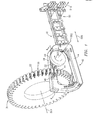
- FIG. 1 shows a machine tool spindle 20 carrying a bit 22 (e.g., an abrasive quill) for rotation in a direction 500 about a spindle axis 502.
- the tool is used to machine a series of blade retention slots from slot precursors 30 extending inward from the periphery 32 of a blade disk 34.
- the disk may be held in a fixture (not shown) for controlled rotation about its axis 504.
- the tool may reciprocally translate the spindle along an axis 506 transverse to the axis 502 to machine the slots.
- the slots are ground from slot precursors having stepped sidewalls, although they may alternatively be ground directly from an uninterrupted periphery.
- FIG. 1 further shows a coolant delivery system 40 having a nozzle 42.
- the nozzle 42 comprises a selective laser sintered (SLS) nozzle body 44 having first and second outlet arms 46 and 48.
- SLS selective laser sintered
- a gap or space 50 between the distal ends of the arms receives the disk when the disk and nozzle are in their operative positions.
- the nozzle may be mounted for movement transverse to the disk such as along a direction 510 by a sliding gantry mechanism 52 supporting the nozzle relative to the tool.
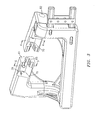
- FIGS. 2 and 3 show further details of the nozzle 42.
- Each of the arms 46 and 48 has a distal end surface 60, 61. Each of these surfaces has an opening 64, 65 at least partially corresponding to a profile of the slots 30. Extending inboard from the opening 64, 65 along an end portion 66, 67 of the associated arm are surfaces 68, 69 which extend to associated inboard surfaces 70, 71 of the end portions. Spaced inboard of the end portions are respective outlet end surfaces 74, 75 having outlet apertures 78, 79. One or more passageways connect the outlet apertures to one or more coolant inlets.
- the nozzle includes respective first and second coolant inlets 82 and 84 to which are connected appropriate fittings and coolant conduits (not shown).
- the first outlet aperture 78 has conjoined first and second portions 86 and 87.
- the first portion 86 (FIG. 4) has a perimeter with an outboard portion 88 and a segmented inboard portion 89 generally parallel to and slightly spaced apart from each other.
- the first portion 86 is formed in a convoluted profile corresponding at least partially to a profile of the bit and thus of the slot once machined.
- the second portion 87 has a perimeter with an inboard portion 90 and a segmented outboard portion 91. Segments of the outboard portion 91 face and at their ends join segments of the inboard portion 89 where the two outlet portions join.
- the second portion 87 is formed with a stepped convoluted profile corresponding at least partially to the profile of the slot precursor.
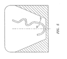
- the second outlet aperture 79 (FIG. 5) has a perimeter with outboard and inboard portions 94 and 96 also generally parallel to and slightly spaced apart from each other.
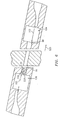
- the outlet aperture 79 and the first portion 86 of the outlet aperture 78 extend along both sides of the bit profile near what would be the tip of the bit and then along only one side along substantially an entire grinding length of the bit. This particular side is chosen so that respective second and first coolant jets 102 and 100 (FIG. 6) expelled from the first outlet aperture impact tangentially with the rotation of the bit (rather than against such rotation) along this side.
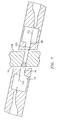
- FIG. 6 specifically shows the bit in an intermediate stage of its traversal along a direction 520.
- the bit has passed from a second receiving bay 106 into a channel defined by the surface 69.
- coolant from the second nozzle aperture 79 impacts the bit as described above, guided by the surface 69 on the first side, however, due to the presence of uncut slot precursor, coolant from the first nozzle aperture 78 first portion 86 (a portion of a jet 100) does not effectively enter the slot precursor and is deflected by the disk first side 108.
- Coolant from the second portion 87 can substantially enter the slot precursor and cool the approaching bit, although impacting slightly less tangentially.
- the bit has passed out of the channel and spanned the gap between the nozzle and the disk and penetrated the second side 110 of the disk to begin to cut the slot from the precursor.
- the surfaces 69 in particular, that portion on the side aligned with the outlet
- the bit will come out the first side 108 of the disk and enter the channel defined by the guide surfaces 68 and reach the first receiving bay 104. Once the bit passes all the way through the first side 108, the portion of the jet 100 from the first outlet aperture first portion 86 can tangentially impact the bit as described above.
- bit/spindle may be retracted and traversed in opposite the direction 520 and reinserted into the second bay. Alternatively it may retraversed back through the machined slot. The disk may then be incrementally rotated to bring the next slot precursor into an operative position, whereupon the procedure is repeated.
Landscapes
- Engineering & Computer Science (AREA)
- Mechanical Engineering (AREA)
- Processing Of Stones Or Stones Resemblance Materials (AREA)
- Perforating, Stamping-Out Or Severing By Means Other Than Cutting (AREA)
- Auxiliary Devices For Machine Tools (AREA)
- Separation By Low-Temperature Treatments (AREA)
- Seasonings (AREA)
- Saccharide Compounds (AREA)
- Heat Treatments In General, Especially Conveying And Cooling (AREA)
- Nozzles (AREA)
Abstract
Description
Claims (10)
- A coolant nozzle (42) for use on a machine tool having a rotating bit (22) of convoluted longitudinal profile for cutting a plurality of slots (30) in a disk (34), the nozzle (42) comprising:at least one coolant inlet (82,84);at least one coolant outlet (78,79) having a convoluted section and positioned to direct a coolant stream (100,102) tangentially at the bit in a direction of rotation of the bit; andinternal surface portions defining one or more passageways between the at least one coolant inlet (82,84) the and at least one coolant outlet (78,79).
- The nozzle of claim 1 wherein the internal surface portions are formed in a laser sintered ceramic body.
- The nozzle of claim 1 or 2 wherein the at least one coolant outlet includes a first outlet (79) and the nozzle (42) further comprises a first guide surface (69) positioned to direct the coolant stream toward the slot (30) so that:with the bit (22) aside the slot (30) between the disk (34) and the first outlet (79), the coolant stream (102) of the first outlet (79) passes laterally between the bit (22) and the first guide surface (69).
- The nozzle of any preceding claim wherein the at least one coolant outlet comprises first and second outlets (78,79) on first and second sides of a disk-receiving space.
- The nozzle of any preceding claim in combination with the machine tool and bit (22) and wherein the nozzle (42) is shiftably mounted to permit the nozzle (42) to be shifted between an operative condition wherein the nozzle (42) blocks longitudinal extraction of the disk (34) from the machine and a cleared condition in which the nozzle (42) does not block said extraction.
- A coolant nozzle (42) for use on a machine tool having a rotating bit (22) for shaping a slot (30) in a workpiece, the nozzle comprising:a gap for accommodating the workpiece in an operative position;at least one coolant inlet (82,84);a first coolant outlet (78) positioned to direct a first coolant stream (100) toward the workpiece from a first side of the workpiece;a second coolant outlet (79) positioned to direct a second coolant stream (102) toward the workpiece from a second side of the workpiece;a first guide surface (68) positioned to direct the first coolant stream (100) toward the slot (30); anda second guide surface (69) positioned to direct the second coolant stream (102) toward the slot (30).
- The coolant nozzle of claim 6 wherein the first and second guide surfaces (68,69) face in substantially opposite directions.
- The coolant nozzle of claim 6 or 7 wherein the first and second guide surfaces (68,69) have convoluted sections corresponding to convoluted first and second side portions of the slot (30) as shaped by the bit (22).
- The coolant nozzle of any of claims 6 to 8 wherein first and second coolant outlets (78,79) have convoluted sections (86) corresponding to said first and second side portions of the slot (30) as shaped by the bit (22).
- The coolant nozzle of any of claims 6 to 9 wherein the first and second guide surfaces (68,69) and first and second outlets (78,79) are on first and second arms of a single sintered ceramic element.
Applications Claiming Priority (2)
| Application Number | Priority Date | Filing Date | Title |
|---|---|---|---|
| US655176 | 1984-09-27 | ||
| US10/655,176 US6991523B2 (en) | 2003-09-04 | 2003-09-04 | Coolant nozzle |
Publications (3)
| Publication Number | Publication Date |
|---|---|
| EP1512491A2 true EP1512491A2 (en) | 2005-03-09 |
| EP1512491A3 EP1512491A3 (en) | 2005-08-17 |
| EP1512491B1 EP1512491B1 (en) | 2007-11-14 |
Family
ID=34136688
Family Applications (1)
| Application Number | Title | Priority Date | Filing Date |
|---|---|---|---|
| EP04255394A Expired - Lifetime EP1512491B1 (en) | 2003-09-04 | 2004-09-06 | Coolant nozzle |
Country Status (6)
| Country | Link |
|---|---|
| US (1) | US6991523B2 (en) |
| EP (1) | EP1512491B1 (en) |
| JP (1) | JP2005081541A (en) |
| AT (1) | ATE378147T1 (en) |
| DE (1) | DE602004010011T2 (en) |
| PL (1) | PL369810A1 (en) |
Family Cites Families (16)
| Publication number | Priority date | Publication date | Assignee | Title |
|---|---|---|---|---|
| US1738646A (en) * | 1926-03-30 | 1929-12-10 | Brown & Sharpe Mfg | Coolant supply for milling machines |
| US3273805A (en) * | 1964-10-02 | 1966-09-20 | Ingersoll Rand Co | Pressurized fluid nozzle assembly |
| US4582149A (en) * | 1981-03-09 | 1986-04-15 | Reed Rock Bit Company | Drill bit having replaceable nozzles directing drilling fluid at a predetermined angle |
| DE3507274A1 (en) * | 1985-03-01 | 1986-09-04 | Arthur Pfeiffer Vakuumtechnik Wetzlar Gmbh, 6334 Asslar | DISC WITH SHOVELS HIGH STABILITY FOR TURBOMOLECULAR PUMPS |
| JPH02100802A (en) * | 1988-10-05 | 1990-04-12 | United Technol Corp <Utc> | Cutting method by high-pressure coolant |
| JPH02109654A (en) | 1988-10-20 | 1990-04-23 | Niigata Eng Co Ltd | Automatic nozzle changing device and coolant feeding method |
| JPH0425309A (en) * | 1990-05-18 | 1992-01-29 | Genichi Sato | Cutting method and device therefore |
| DE4129402A1 (en) | 1991-09-04 | 1993-03-11 | Blohm Maschinenbau Gmbh | COOLING DEVICE FOR A GRINDING MACHINE |
| US5203122A (en) * | 1992-06-05 | 1993-04-20 | United Technologies Corporation | Method of grinding titanium |
| US5430936A (en) | 1993-12-27 | 1995-07-11 | United Technologies Corporation | Method for making gas turbine engine blade attachment slots |
| JPH07241770A (en) * | 1994-03-08 | 1995-09-19 | Nissan Motor Co Ltd | Grinding liquid supply device |
| GB9418039D0 (en) * | 1994-09-07 | 1994-10-26 | Reckitt & Colmann Prod Ltd | Electrostatic spraying device |
| JP3787739B2 (en) * | 1998-01-26 | 2006-06-21 | トヨタ自動車株式会社 | Machining equipment using cold air cooling |
| US6050163A (en) * | 1999-01-15 | 2000-04-18 | Cutting Edge Designs, L.L.C. | Saw blade having liquid transport cavity for use with lubricating guide support assembly |
| JP2000308954A (en) * | 1999-04-26 | 2000-11-07 | Toyoda Mach Works Ltd | Internal groove processing equipment |
| US6302651B1 (en) | 1999-12-29 | 2001-10-16 | United Technologies Corporation | Blade attachment configuration |
-
2003
- 2003-09-04 US US10/655,176 patent/US6991523B2/en not_active Expired - Lifetime
-
2004
- 2004-08-30 PL PL04369810A patent/PL369810A1/en not_active IP Right Cessation
- 2004-09-06 AT AT04255394T patent/ATE378147T1/en not_active IP Right Cessation
- 2004-09-06 DE DE602004010011T patent/DE602004010011T2/en not_active Expired - Lifetime
- 2004-09-06 EP EP04255394A patent/EP1512491B1/en not_active Expired - Lifetime
- 2004-09-06 JP JP2004257859A patent/JP2005081541A/en not_active Ceased
Also Published As
| Publication number | Publication date |
|---|---|
| PL369810A1 (en) | 2005-03-07 |
| EP1512491B1 (en) | 2007-11-14 |
| JP2005081541A (en) | 2005-03-31 |
| DE602004010011T2 (en) | 2008-09-11 |
| US6991523B2 (en) | 2006-01-31 |
| ATE378147T1 (en) | 2007-11-15 |
| EP1512491A3 (en) | 2005-08-17 |
| DE602004010011D1 (en) | 2007-12-27 |
| US20050053433A1 (en) | 2005-03-10 |
Similar Documents
| Publication | Publication Date | Title |
|---|---|---|
| EP0514604B1 (en) | Repair of airfoil edges | |
| US6302625B1 (en) | Method and apparatus for refurbishing a gas turbine airfoil | |
| JP2609016B2 (en) | Attachment for machining a gas turbine rotor, method of machining without removing an exposed rotor from its frame, and method of machining a compressor rotor blade damper pocket | |
| US8286348B2 (en) | Method of manufacturing and refinishing integrally bladed rotors | |
| US7337520B2 (en) | Method for utilizing fixture having integrated datum locators | |
| US20090075564A1 (en) | Superabrasive tool and machining methods | |
| RU2539713C2 (en) | Optimised production of blade single-unit disc by abrasive water jet | |
| US7967659B2 (en) | Method of machining integral bladed rotors for a gas turbine engine | |
| JPH05220602A (en) | Contouring device | |
| CN101980820A (en) | Improved method for producing a one-piece bladed disc, with temporary blade-supporting ring which is removed after a finish-milling step | |
| RU2534904C2 (en) | Optimised production of single-unit impeller by abrasive water jet | |
| GB2455622A (en) | A plunge milling method | |
| US7582004B2 (en) | Coolant nozzle | |
| US6991434B2 (en) | Method of producing components subjected to flow, and components made by said method | |
| EP1955812B1 (en) | Blade feature machining | |
| US8014893B2 (en) | Method of machining workpiece with offset tool | |
| US8689441B2 (en) | Method for machining a slot in a turbine engine rotor disk | |
| CN101980823A (en) | Method for producing a one-piece bladed disc by abrasive water-jet cutting | |
| US6991523B2 (en) | Coolant nozzle | |
| CN102917824B (en) | Method for machining grooves in a turbomachine turbine disc |
Legal Events
| Date | Code | Title | Description |
|---|---|---|---|
| PUAI | Public reference made under article 153(3) epc to a published international application that has entered the european phase |
Free format text: ORIGINAL CODE: 0009012 |
|
| AK | Designated contracting states |
Kind code of ref document: A2 Designated state(s): AT BE BG CH CY CZ DE DK EE ES FI FR GB GR HU IE IT LI LU MC NL PL PT RO SE SI SK TR |
|
| AX | Request for extension of the european patent |
Extension state: AL HR LT LV MK |
|
| PUAL | Search report despatched |
Free format text: ORIGINAL CODE: 0009013 |
|
| AK | Designated contracting states |
Kind code of ref document: A3 Designated state(s): AT BE BG CH CY CZ DE DK EE ES FI FR GB GR HU IE IT LI LU MC NL PL PT RO SE SI SK TR |
|
| AX | Request for extension of the european patent |
Extension state: AL HR LT LV MK |
|
| RIC1 | Information provided on ipc code assigned before grant |
Ipc: 7B 23C 3/30 B Ipc: 7B 23Q 11/10 A |
|
| 17P | Request for examination filed |
Effective date: 20050901 |
|
| AKX | Designation fees paid |
Designated state(s): AT BE BG CH CY CZ DE DK EE ES FI FR GB GR HU IE IT LI LU MC NL PL PT RO SE SI SK TR |
|
| GRAP | Despatch of communication of intention to grant a patent |
Free format text: ORIGINAL CODE: EPIDOSNIGR1 |
|
| GRAS | Grant fee paid |
Free format text: ORIGINAL CODE: EPIDOSNIGR3 |
|
| GRAA | (expected) grant |
Free format text: ORIGINAL CODE: 0009210 |
|
| AK | Designated contracting states |
Kind code of ref document: B1 Designated state(s): AT BE BG CH CY CZ DE DK EE ES FI FR GB GR HU IE IT LI LU MC NL PL PT RO SE SI SK TR |
|
| REG | Reference to a national code |
Ref country code: GB Ref legal event code: FG4D |
|
| REG | Reference to a national code |
Ref country code: CH Ref legal event code: EP |
|
| REG | Reference to a national code |
Ref country code: IE Ref legal event code: FG4D |
|
| REF | Corresponds to: |
Ref document number: 602004010011 Country of ref document: DE Date of ref document: 20071227 Kind code of ref document: P |
|
| PG25 | Lapsed in a contracting state [announced via postgrant information from national office to epo] |
Ref country code: LI Free format text: LAPSE BECAUSE OF FAILURE TO SUBMIT A TRANSLATION OF THE DESCRIPTION OR TO PAY THE FEE WITHIN THE PRESCRIBED TIME-LIMIT Effective date: 20071114 Ref country code: SE Free format text: LAPSE BECAUSE OF FAILURE TO SUBMIT A TRANSLATION OF THE DESCRIPTION OR TO PAY THE FEE WITHIN THE PRESCRIBED TIME-LIMIT Effective date: 20080214 Ref country code: NL Free format text: LAPSE BECAUSE OF FAILURE TO SUBMIT A TRANSLATION OF THE DESCRIPTION OR TO PAY THE FEE WITHIN THE PRESCRIBED TIME-LIMIT Effective date: 20071114 Ref country code: CH Free format text: LAPSE BECAUSE OF FAILURE TO SUBMIT A TRANSLATION OF THE DESCRIPTION OR TO PAY THE FEE WITHIN THE PRESCRIBED TIME-LIMIT Effective date: 20071114 Ref country code: ES Free format text: LAPSE BECAUSE OF FAILURE TO SUBMIT A TRANSLATION OF THE DESCRIPTION OR TO PAY THE FEE WITHIN THE PRESCRIBED TIME-LIMIT Effective date: 20080225 |
|
| NLV1 | Nl: lapsed or annulled due to failure to fulfill the requirements of art. 29p and 29m of the patents act | ||
| PG25 | Lapsed in a contracting state [announced via postgrant information from national office to epo] |
Ref country code: FI Free format text: LAPSE BECAUSE OF FAILURE TO SUBMIT A TRANSLATION OF THE DESCRIPTION OR TO PAY THE FEE WITHIN THE PRESCRIBED TIME-LIMIT Effective date: 20071114 Ref country code: PL Free format text: LAPSE BECAUSE OF FAILURE TO SUBMIT A TRANSLATION OF THE DESCRIPTION OR TO PAY THE FEE WITHIN THE PRESCRIBED TIME-LIMIT Effective date: 20071114 Ref country code: BG Free format text: LAPSE BECAUSE OF FAILURE TO SUBMIT A TRANSLATION OF THE DESCRIPTION OR TO PAY THE FEE WITHIN THE PRESCRIBED TIME-LIMIT Effective date: 20080214 Ref country code: SI Free format text: LAPSE BECAUSE OF FAILURE TO SUBMIT A TRANSLATION OF THE DESCRIPTION OR TO PAY THE FEE WITHIN THE PRESCRIBED TIME-LIMIT Effective date: 20071114 |
|
| REG | Reference to a national code |
Ref country code: CH Ref legal event code: PL |
|
| PG25 | Lapsed in a contracting state [announced via postgrant information from national office to epo] |
Ref country code: AT Free format text: LAPSE BECAUSE OF FAILURE TO SUBMIT A TRANSLATION OF THE DESCRIPTION OR TO PAY THE FEE WITHIN THE PRESCRIBED TIME-LIMIT Effective date: 20071114 |
|
| ET | Fr: translation filed | ||
| PG25 | Lapsed in a contracting state [announced via postgrant information from national office to epo] |
Ref country code: CZ Free format text: LAPSE BECAUSE OF FAILURE TO SUBMIT A TRANSLATION OF THE DESCRIPTION OR TO PAY THE FEE WITHIN THE PRESCRIBED TIME-LIMIT Effective date: 20071114 Ref country code: DK Free format text: LAPSE BECAUSE OF FAILURE TO SUBMIT A TRANSLATION OF THE DESCRIPTION OR TO PAY THE FEE WITHIN THE PRESCRIBED TIME-LIMIT Effective date: 20071114 |
|
| PG25 | Lapsed in a contracting state [announced via postgrant information from national office to epo] |
Ref country code: SK Free format text: LAPSE BECAUSE OF FAILURE TO SUBMIT A TRANSLATION OF THE DESCRIPTION OR TO PAY THE FEE WITHIN THE PRESCRIBED TIME-LIMIT Effective date: 20071114 Ref country code: BE Free format text: LAPSE BECAUSE OF FAILURE TO SUBMIT A TRANSLATION OF THE DESCRIPTION OR TO PAY THE FEE WITHIN THE PRESCRIBED TIME-LIMIT Effective date: 20071114 Ref country code: RO Free format text: LAPSE BECAUSE OF FAILURE TO SUBMIT A TRANSLATION OF THE DESCRIPTION OR TO PAY THE FEE WITHIN THE PRESCRIBED TIME-LIMIT Effective date: 20071114 |
|
| PLBE | No opposition filed within time limit |
Free format text: ORIGINAL CODE: 0009261 |
|
| STAA | Information on the status of an ep patent application or granted ep patent |
Free format text: STATUS: NO OPPOSITION FILED WITHIN TIME LIMIT |
|
| PG25 | Lapsed in a contracting state [announced via postgrant information from national office to epo] |
Ref country code: PT Free format text: LAPSE BECAUSE OF FAILURE TO SUBMIT A TRANSLATION OF THE DESCRIPTION OR TO PAY THE FEE WITHIN THE PRESCRIBED TIME-LIMIT Effective date: 20080414 |
|
| 26N | No opposition filed |
Effective date: 20080815 |
|
| PG25 | Lapsed in a contracting state [announced via postgrant information from national office to epo] |
Ref country code: GR Free format text: LAPSE BECAUSE OF FAILURE TO SUBMIT A TRANSLATION OF THE DESCRIPTION OR TO PAY THE FEE WITHIN THE PRESCRIBED TIME-LIMIT Effective date: 20080215 |
|
| PG25 | Lapsed in a contracting state [announced via postgrant information from national office to epo] |
Ref country code: MC Free format text: LAPSE BECAUSE OF NON-PAYMENT OF DUE FEES Effective date: 20080930 Ref country code: EE Free format text: LAPSE BECAUSE OF FAILURE TO SUBMIT A TRANSLATION OF THE DESCRIPTION OR TO PAY THE FEE WITHIN THE PRESCRIBED TIME-LIMIT Effective date: 20071114 |
|
| PG25 | Lapsed in a contracting state [announced via postgrant information from national office to epo] |
Ref country code: IE Free format text: LAPSE BECAUSE OF NON-PAYMENT OF DUE FEES Effective date: 20080908 Ref country code: CY Free format text: LAPSE BECAUSE OF FAILURE TO SUBMIT A TRANSLATION OF THE DESCRIPTION OR TO PAY THE FEE WITHIN THE PRESCRIBED TIME-LIMIT Effective date: 20071114 |
|
| PG25 | Lapsed in a contracting state [announced via postgrant information from national office to epo] |
Ref country code: LU Free format text: LAPSE BECAUSE OF NON-PAYMENT OF DUE FEES Effective date: 20080906 Ref country code: HU Free format text: LAPSE BECAUSE OF FAILURE TO SUBMIT A TRANSLATION OF THE DESCRIPTION OR TO PAY THE FEE WITHIN THE PRESCRIBED TIME-LIMIT Effective date: 20080515 |
|
| PG25 | Lapsed in a contracting state [announced via postgrant information from national office to epo] |
Ref country code: TR Free format text: LAPSE BECAUSE OF FAILURE TO SUBMIT A TRANSLATION OF THE DESCRIPTION OR TO PAY THE FEE WITHIN THE PRESCRIBED TIME-LIMIT Effective date: 20071114 |
|
| PGFP | Annual fee paid to national office [announced via postgrant information from national office to epo] |
Ref country code: FR Payment date: 20100921 Year of fee payment: 7 |
|
| PG25 | Lapsed in a contracting state [announced via postgrant information from national office to epo] |
Ref country code: IT Free format text: LAPSE BECAUSE OF NON-PAYMENT OF DUE FEES Effective date: 20080930 |
|
| REG | Reference to a national code |
Ref country code: FR Ref legal event code: ST Effective date: 20120531 |
|
| PG25 | Lapsed in a contracting state [announced via postgrant information from national office to epo] |
Ref country code: FR Free format text: LAPSE BECAUSE OF NON-PAYMENT OF DUE FEES Effective date: 20110930 |
|
| PGFP | Annual fee paid to national office [announced via postgrant information from national office to epo] |
Ref country code: GB Payment date: 20160825 Year of fee payment: 13 Ref country code: DE Payment date: 20160823 Year of fee payment: 13 |
|
| REG | Reference to a national code |
Ref country code: DE Ref legal event code: R082 Ref document number: 602004010011 Country of ref document: DE Representative=s name: SCHMITT-NILSON SCHRAUD WAIBEL WOHLFROM PATENTA, DE |
|
| REG | Reference to a national code |
Ref country code: DE Ref legal event code: R082 Ref document number: 602004010011 Country of ref document: DE Representative=s name: SCHMITT-NILSON SCHRAUD WAIBEL WOHLFROM PATENTA, DE Ref country code: DE Ref legal event code: R081 Ref document number: 602004010011 Country of ref document: DE Owner name: UNITED TECHNOLOGIES CORP. (N.D.GES.D. STAATES , US Free format text: FORMER OWNER: UNITED TECHNOLOGIES CORP., HARTFORD, CONN., US |
|
| REG | Reference to a national code |
Ref country code: DE Ref legal event code: R119 Ref document number: 602004010011 Country of ref document: DE |
|
| GBPC | Gb: european patent ceased through non-payment of renewal fee |
Effective date: 20170906 |
|
| PG25 | Lapsed in a contracting state [announced via postgrant information from national office to epo] |
Ref country code: DE Free format text: LAPSE BECAUSE OF NON-PAYMENT OF DUE FEES Effective date: 20180404 Ref country code: GB Free format text: LAPSE BECAUSE OF NON-PAYMENT OF DUE FEES Effective date: 20170906 |