EP1512431A1 - Elektrostimulator - Google Patents
Elektrostimulator Download PDFInfo
- Publication number
- EP1512431A1 EP1512431A1 EP04090236A EP04090236A EP1512431A1 EP 1512431 A1 EP1512431 A1 EP 1512431A1 EP 04090236 A EP04090236 A EP 04090236A EP 04090236 A EP04090236 A EP 04090236A EP 1512431 A1 EP1512431 A1 EP 1512431A1
- Authority
- EP
- European Patent Office
- Prior art keywords
- stimulation
- electro
- stimulation pulse
- signal
- detection unit
- Prior art date
- Legal status (The legal status is an assumption and is not a legal conclusion. Google has not performed a legal analysis and makes no representation as to the accuracy of the status listed.)
- Granted
Links
Images


Classifications
-
- A—HUMAN NECESSITIES
- A61—MEDICAL OR VETERINARY SCIENCE; HYGIENE
- A61N—ELECTROTHERAPY; MAGNETOTHERAPY; RADIATION THERAPY; ULTRASOUND THERAPY
- A61N1/00—Electrotherapy; Circuits therefor
- A61N1/18—Applying electric currents by contact electrodes
- A61N1/32—Applying electric currents by contact electrodes alternating or intermittent currents
- A61N1/36—Applying electric currents by contact electrodes alternating or intermittent currents for stimulation
- A61N1/362—Heart stimulators
- A61N1/37—Monitoring; Protecting
- A61N1/371—Capture, i.e. successful stimulation
- A61N1/3712—Auto-capture, i.e. automatic adjustment of the stimulation threshold
Definitions
- the invention relates to an electrostimulator with electrode terminals, the at least temporarily with an electrostimulation unit and simultaneously or alternately connect to a detection unit of the electrostimulator are.
- the stimulation unit is designed, electrostimulation pulses to generate stimulation of body tissue and at least one of Dispense electrode connections.
- the detection unit is designed, a successful stimulation of body tissue by means of one at least one Electrode connection to detect applied electrical signal.
- the electrostimulator is formed, via which with the detection unit connected electrode connection an electrocardiac electrocardiogram to record the representative electrical signal.
- Such electrostimulators are in particular as implantable pacemakers but also as a cardioverter / defibrillator or as a combination device known.
- Such electrostimulators serve primarily to electrostimulation pulses to donate to a heart's myocardium to make the heart stimulated by the electrostimulation pulse to contract. This must be the Electrostimulation pulse above the threshold of the myocardium lie. Therefore An electrical stimulation pulse requires electrical energy, in particular in the case of an implant, a battery of limited capacity too and, in the case of a depleted battery, surgery is required Basically, there is a need for a successful electrostimulation pulse to keep the required energy as low as possible, without jeopardizing the success of electrostimulation.
- the success of electrical stimulation i.e. the response of the myocardium to a stimulation pulse is commonly referred to by the English word "capture".
- pacemakers To be able to perform a stimulation success check, have pacemakers often detection units on to successful electrostimulation to detect. Such a detection unit is also called a capture detector designated.
- the present invention applies to the aspect of capture detection in electrostimulators like pacemakers or the like.
- Other aspects pacemaker control such as setting an adequate one Stimulation rate or the inhibition of stimulation pulses in the case of natural contractions of the heart are not in the foreground and are known to those skilled in principle.
- an electro-stimulator of the invention Input type mentioned above, in which between the electrode connection for the uptake of the intracardiac electrocardiogram electrical signal and the detection unit a high-pass filter with a lower limit frequency> 100 Hz is arranged and in which the detection unit is designed to evaluate the high-pass filtered electrical signal.
- the invention is based on the finding that the higher-frequency components of an intracardiac electrocardiogram especially of the immediate Near a sensing electrode lying myocardium are determined and less of more distant events, so basically, for example Known problems such as Crosstalk in the inventive arrangement can be easily suppressed.
- the evaluation of the electrocardiogram allows in the immediate vicinity of a corresponding sensing electrode, a stimulation success already in a period of a few Milliseconds after stimulation pulse delivery.
- the electrostimulator is formed, which is an intracardiac electrocardiogram representing electrical signal via a bipolar E-lektrodenkonfiguration take.
- the electrode connection for receiving the intracardiac electrocardiogram representing electrical signal connected to at least a bipolar electrode line, which at least two electrodes for receiving the electrodes having applied electrical potentials.
- the electrodes preferably have a low polarization tendency, i. a low post-potential after electrostimulation. Therefore, in particular, such electrodes preferred, which have a particularly large effective electrode surface, which is preferably achieved with a fractal coating.
- the invention is based on the recognition that in a bipolar measuring arrangement using an electrode lead with a tip and a ring electrode for the recording of the intracardiac electrocardiogram only cardiac Activities are recorded by a small area of tissue around the Electrodes come and that such an intracardiac electrocardiogram have significant signal components beyond 100 Hz.
- usual and known pacemakers operate with low-pass filters with an upper limit frequency of the order of 100 Hz, so that usually signal components with frequency components above 50 to 200 Hz can be suppressed.
- the detection unit is designed in a preferred embodiment variant to a successful stimulation, so a capture, to detect and then generate a corresponding capture signal.
- a successful stimulation based on a short-term peak in which an intracardiac electrocardiogram detected representative electrical signal and preferably by thresholding within a defined time window, which is started with delivery of a stimulation pulse.
- an electrostimulator that has a stimulation control unit which is connected to the stimulation unit and the detection unit in such a way and is configured such that the stimulation control unit from the temporal Distance between stimulation pulse and capture signal a stimulation pulse strength signal determines which of the strengths, in particular the amplitude, a subsequent stimulation pulse generated by the stimulation unit certainly.
- This preferred embodiment is based on the following explained in more detail realization that the duration between delivery a stimulation pulse and occurrence of a stimulation success thereof depends on how much suprathreshold a respective stimulation pulse is.
- a stimulation success While in a very suprathreshold stimulation pulse (amplitude, for example four times greater than the threshold) after less than 5 ms a stimulation success occurs, pass in a barely suprathreshold Stimulation pulse, for example, more than 15 ms between stimulation pulse delivery and entry of stimulation success. As time of entry of the stimulation success is the respective characteristic peak in the intracardiac recorded and high-pass filtered electrocardiogram scored.
- the stimulation pulse strength i.e. in particular the amplitude of a stimulation pulse each set so that the stimulation pulse just the Required strength including any desired safety margin without unnecessarily consuming much energy.
- the stimulation control unit is preferably designed the time interval between delivery of a stimulation pulse and the to compare the following capture signal with a reference time value and adjust the stimulation pulse strength signal such that the strength a respective stimulation pulse with a shorter time interval between Delivering a stimulation pulse and the subsequent capture signal decreases, as long as the time interval is not the reference time value below.
- the reference time value is preferred in this context set such that it has a sufficiently suprathreshold stimulation equivalent. Setting the reference time value may be, for example after implantation of an electrostimulator by the attending physician or in an independent learning phase in which the electrostimulator several stimulation pulses subliminal and more supple Gives strength and the longest, between stimulation pulse delivery and Onset of stimulation success measures elapsed time. This time corresponds the latency between stimulation pulse delivery and the occurrence of the Stimulation success, which is then measured when the stimulation pulse strength just the stimulus threshold corresponds. For security reasons, the Reference value set slightly shorter than the latency thus determined.
- the stimulation control unit is preferably designed such that that in the case of lack of stimulation success within a predetermined time window after delivery of the stimulation pulse one Back-up stimulation pulse triggers that has a greater strength than the previously unsuccessful stimulation pulse.
- an electrostimulator which with a telemetry unit is provided with which values for the time interval between a Stimulation pulse and the subsequent stimulation success in to have an external device transmitted. These values are preferably as Value pairs transmitted together with the associated stimulation pulse strength. The transmission of the time interval values and, if applicable, the associated ones Pacing pulse strengths can be done in real time. Alternatively, you can also, a memory may be provided in which several of these values are stored and either at a scheduled time or at one Query sent out.
- FIG. 1 is a schematic representation of an electrostimulator 10, the particular an implantable pacemaker but also a cardioverter / defibrillator or both can be.
- the electrostimulator 10 is at least with the two shown in Figure 1 Electrode connections 12 and 14 for a right ventricular ring and a right ventricular tip electrode provided. Instead of a ring and a tip electrode can also be provided two ring electrodes.
- the order The electrodes in the right ventricle correspond to the most common application. An arrangement in a coronary vein branching off from the coronary sinus, thus assigned to the left ventricle, or even on the left atrium is also possible.
- a voltage measuring unit 16 provided which with the electrode terminals is connected and a respectively determined voltage signal to a capture detector 18 passes.
- the capture detector 18 serves as a detection unit in the sense of the claims.
- the capture detector 18 is formed, the high-frequency intracardiac electrocardiogram evaluate. Examples of such electrocardiograms in the case of a natural and a stimulated contraction of the heart shown in Figures 2 and 3, respectively.
- the capture detector 18 is configured, one for successful stimulation characteristic peak in the high-pass filtered electrocardiogram too detect as shown in Figure 3.
- the capture detector is still on designed to detect such peaks that are within a given Time window after delivery of a stimulation pulse occur. This is the Capture detector with a timer started as soon as one Stimulation pulse is delivered.
- the capture detector 18 is further configured to use the timer Time interval to determine between the delivery of a respective stimulation pulse and onset of stimulation success.
- the capture detector derives from the time interval from a time interval signal, which is the Capture detector to a stimulation control unit 20 passes.
- the capture detector 18 generates a capture signal when the Capture detector 18 within the predetermined time window in the high-pass filtered intracardiac electrocardiogram a stimulation success detected by the characteristic peak. In the opposite case, if within of the time window no stimulation success is determined, the generated Capture detector 18 is a non-capture signal. Both the capture signal as also the non-capture signal from the capture detector 18 to the stimulation control unit 20 passed.
- the stimulation control unit 20 triggers in the case of a non-capture signal from the side the capture detector 18 immediately a back-up stimulation pulse out.
- the stimulation control unit 20 is provided with a Stimulation unit 22 connected.
- the back-up stimulus pulse has a greater strength, in particular a larger amplitude than the previously unsuccessful Stimulation pulse.
- a capture signal from the capture detector 18 evaluates the Pacing control unit 20, the time interval signal and determines whether and in a preferred embodiment also by how much the time interval between delivery of a stimulation pulse and the occurrence of stimulation success (Capture signal) is shorter than a previously stored reference time value. As long as the time interval, given by the time interval signal, is shorter than the reference time value, generates the pacing control unit 20 a stimulation pulse strength signal representing the stimulation unit 22 causes the next stimulation pulse to be lower Starch, i. deliver with a lower amplitude.
- the short-circuit switch is in the inventive Electrostimulator for a maximum of 5 ms after delivery of a stimulation pulse closed to enter in direct connection to this 5 ms to record intracardiac electrocardiograms. This must be the Short-circuit switch be opened again, i. the two electrode connections 12 and 14 are not shorted.
- an optional telemetry unit 24 Shown in dashed lines in Figure 1 is an optional telemetry unit 24, the is connected via a memory 26 to the stimulation control unit 20.
- the telemetry unit 24 serves to stored in the memory 26 time interval signals and associated stimulation pulse strengths in pairs to one telemetric transmission of external device.
- the telemetry unit 24 is with an indicated in Figure 1 antenna 28 is connected.
- time interval values and the associated stimulation amplitudes can then be done in an external device, for example to determine a suitable reference time value. This allows the internal electrostimulator Pacing control unit simpler than previously described.
- Figure 2 shows an intracardiac electrocardiogram of an intrinsic event as it goes along with a natural heart contraction.
- the intracardiac Electrocardiogram is high pass filtered with a high pass filter first Order and a cut-off frequency of 500 Hz.
- the two vertical bars represent periods in which the corresponding heart is not effective a pacemaker was stimulated and therefore excluded from the presentation were.
- the intracardiac electrocardiogram is recorded with a bipolar Measuring arrangement, in which the ring and the tip electrode of a single Electrode lead were used for the uptake of tissue potentials.
- the recorded tissue potentials were high-pass filtered. This resulted in the sharp signal peaks shown in FIG. These signal peaks go hand in hand with a rise phase of a local action potential.
- the bipolar sensing arrangement ensures that only electrical activity is off the next environment of the electrodes are measured. Activities of others Heart chambers or skeletal muscles are severely suppressed. This reduced both a possible crosstalk perception (perception of Activities of cardiac chambers other than that in which it is measured) as well as Capture muscular activity. This effect is due to the high pass filtering the signal amplified further. Shifts in a bipolar measuring device the curve of the frequency response is all the more towards lower Frequencies, the greater the measuring distance becomes. With increasing distance From the measuring location higher frequency components are reduced more as low-frequency signal components. Therefore, by the high-pass filtering the measurement signal crosstalk and the perception of skeletal muscle activities even further reduced than by the bipolar measuring arrangement already given.
- a pacemaker closes the stimulation electrodes usually short (during a so-called autoshort period) to drain charges that are accumulated on the electrode surface during stimulation.
- the duration of this autoshort period is usually 10 to 20 ms, so that the rising phase of action potentials that respond to a stimulation pulse going back can not be perceived. Therefore, the Heart stimulator designed in a preferred embodiment, to switch an autoshort period of not more than 5 ms. Nevertheless To keep Nachpotentiale on the electrodes as low as possible, they are with the largest possible active surface provided by a fractal Coating is achieved.
- Figure 3 shows a high pass filtered intracardiac electrocardiogram in response on a stimulation pulse.
- a characteristic of stimulation success sharp negative peak follows the stimulation pulse within 15 ms.
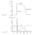
- FIG. 4 shows the typical course of action potentials of the cell membranes of the myocardium following electrical stimulation.
- the action potentials with the leftmost surge phase are pacing pulses greater strength (greater voltage, energy) back, the farther right action potential courses on a stimulation with weaker Stimulation pulses.
- the courses of the action potentials are similar. However, with stimulation pulses close to the stimulus threshold of the myocardium (slightly suprathreshold) to realize that the membrane potential initially remains on a slightly elevated plateau for a few milliseconds, before the actual rise phase of the action potential course occurs.
- This rise phase of the action potential course is reflected in a peak in a corresponding high-pass filtered intracardiac electrocardiogram again.
- Such electrocardiograms for different stimulation pulse strengths are shown in FIG. It can be seen that the Peak in the intracardiac electrocardiogram occurs the later the lower is the stimulation pulse.
- This time difference between the occurrence a peak in the intracardiac electrocardiogram for a stimulation pulse which is just overblown, and one that is four times as big as the Threshold of the myocardium is about 10 to 15 ms.
- the position of a peak in the intracardiac electrocardiogram is therefore a Indicator of how much the amplitude of a stimulation pulse above the threshold is.
- the claimed Electrostimulator therefore, formed the strength of a stimulation pulse depending on the duration between the delivery of a Stimulation pulse and occurrence of the peak in the high-pass filtered intracardiac Electrocardiogram passes. Is this time very short, for example less than 5 to 10 ms, may be the strength of the stimulation pulse be reduced without the stimulation success for the next stimulation pulse to endanger.
- This is in contrast to other known pacemakers with a so-called auto-capture algorithm, in which the Stimulation pulse amplitude is reduced regularly until no Stimulation pulse is more detectable. Only then does the stimulation pulse amplitude become slightly raised again.
- auto-capture algorithms regularly a lack of stimulation success in Purchase.
- the preferred electrostimulator is therefore preferably in an initial state Learning phase automatically a reference time value for the time interval between stimulation impulse delivery and the occurrence of the stimulus response, below which a successful stimulation is regularly ensured.
- the pacing control unit of the Pacemaker's stimulation intensity regularly such that the respective measured value is slightly below the reference time value or this corresponds.
- FIGS. 6a and 6b serve to further explain the behavior of the Myocardium following electrical stimulation.
Landscapes
- Health & Medical Sciences (AREA)
- Animal Behavior & Ethology (AREA)
- Veterinary Medicine (AREA)
- Engineering & Computer Science (AREA)
- Biomedical Technology (AREA)
- Nuclear Medicine, Radiotherapy & Molecular Imaging (AREA)
- Radiology & Medical Imaging (AREA)
- Heart & Thoracic Surgery (AREA)
- General Health & Medical Sciences (AREA)
- Life Sciences & Earth Sciences (AREA)
- Public Health (AREA)
- Cardiology (AREA)
- Electrotherapy Devices (AREA)
- Measurement And Recording Of Electrical Phenomena And Electrical Characteristics Of The Living Body (AREA)
- Electrolytic Production Of Non-Metals, Compounds, Apparatuses Therefor (AREA)
- Piezo-Electric Or Mechanical Vibrators, Or Delay Or Filter Circuits (AREA)
Abstract
Description
- Figur 1
- eine schematische Darstellung eines erfindungsgemäßen Elektrostimulators;
- Figur 2
- ein Beispiel für ein intrakardiales Elektrokardiogramm, welches natürliche Herzkontraktionen repräsentiert;
- Figur 3
- ein Beispiel eines intrakardialen Elektrokardiogramms, welches Gewebepotentiale nach erfolgreicher Elektrostimulation repräsentiert;
- Figur 4
- Aktionspotentiale des Myocards im Anschluss an eine erfolgreiche Elektrostimulation für verschiedene Stimulationsstärken;
- Figur 5
- verschiedene Elektrokardiogramme, die die Reizantwort des Myocards bei Stimulation mit verschiedenen Stimulationsstärken repräsentieren;
- Figur 6a
- eine schematische Darstellung eines Aktionspotentials; und
- Figur 6b
- eine Darstellung der lonenleitfähigkeit und der lonenströme, die zu dem in Figur 6a dargestellten Aktionspotentialverlauf führen.
Claims (14)
- Elektrostimulator mit Elektrodenanschlüssen (12, 14), die wenigstens zeitweise mit einer Stimulationseinheit (22) und einer Detektionseinheit (18) des Elektrostimulators zu verbinden sind, wobei die Stimulationseinheit (22) ausgebildet ist, Elektrostimulationsimpulse zur Stimulation von Körpergewebe zu generieren und an wenigstens einen der Elektrodenanschlüsse (12, 14) abzugeben und wobei die Detektionseinheit (18) dazu ausgebildet ist, eine erfolgreiche Stimulation von Körpergewebe anhand eines an wenigstens einem Elektrodenanschluss anliegendem elektrischen Signal zu detektieren, wobei der Elektrostimulator ausgebildet ist, über diesen wenigstens einen Elektrodenanschluss ein intrakardiales Elektrokardiogramm repräsentierendes elektrisches Signal aufzunehmen,
dadurch gekennzeichnet, dass zwischen dem Elektrodenleitungsanschluss und der Detektionseinheit ein Hochpassfilter mit einer unteren Grenzfrequenz größer 100 Hz angeordnet ist und die Detektionseinheit ausgebildet ist, das hochpassgefilterte elektrische Signal auszuwerten. - Elektrostimulator nach Anspruch 1, dadurch gekennzeichnet, dass der Elektrostimulator ausgebildet ist, das ein intrakardiales Elektrokardiogramm repräsentierende elektrische Signal über eine bipolare Elektrodenkonfiguration aufzunehmen.
- Elektrostimulator nach Anspruch 2, dadurch gekennzeichnet, dass an dem Elektrodenanschluss zur Aufnahme des ein intrakardiales Elektrokardiogramm repräsentierenden elektrischen Signals eine wenigstens bipolare Elektrodenleitung angeschlossen ist, welche wenigstens zwei Elektroden für die Aufnahme an den Elektrodenanliegender elektrischer Potentiale aufweist, wobei die Elektroden eine geringe Polarisation aufweisen.
- Elektrostimulator nach Anspruch 3, dadurch gekennzeichnet, dass die Elektroden eine fraktale Beschichtung aufweisen.
- Elektrostimulator nach einem der Ansprüche 1 bis 4, dadurch gekennzeichnet, dass der Elektrostimulator eine Autoshorteinrichtung zum Kurzschließen von Stimulationselektroden aufweist, die ausgebildet ist, die Elektroden nicht länger als 5 Millisekunden kurzzuschließen.
- Elektrostimulator nach einem der Ansprüche 1 bis 5, dadurch gekennzeichnet, dass die Detektionseinheit ausgebildet ist, eine erfolgreiche Stimulation (capture) zu detektieren und ein Capture-Signal zu erzeugen.
- Elektrostimulator nach Anspruch 6, dadurch gekennzeichnet, dass die Detektionseinheit ausgebildet ist, eine erfolgreiche Stimulation anhand eines kurzfristigen Peaks in dem ein intrakardiales Elektrokardiogramm repräsentierenden elektrischen Signal zu detektieren.
- Elektrostimulator nach Anspruch 7, dadurch gekennzeichnet, dass die Detektionseinheit ausgebildet ist, einen kurzfristigen Peak in dem ein intrakardiales Elektrokardiogramm repräsentierenden elektrischen Signal innerhalb eines definierten Zeitfensters zu detektieren, welches mit Abgabe eines Stimulationsimpulses gestartet wird.
- Elektrostimulator nach Anspruch 6 und einem der übrigen Ansprüche, gekennzeichnet durch eine Stimulationssteuereinheit, die mit der Stimulationseinheit und der Detektionseinheit derart verbunden und ausgebildet ist, dass die Stimulationssteuereinheit aus dem zeitlichen Abstand zwischen Stimulationsimpuls und Capture Signal ein Stimulationsimpulsstärkensignal ermittelt, welches die Stärke eines folgenden, durch die Stimulationseinheit erzeugten Stimulationsimpulses bestimmt.
- Elektrostimulator nach Anspruch 9, dadurch gekennzeichnet, dass die Stimulationssteuereinheit ausgebildet ist, den zeitlichen Abstand zwischen Abgabe eines Stimulationsimpulses und dem darauf folgenden Capture-Signal mit einem Referenzzeitwert zu vergleichen, und das Stimulationsimpulsstärkensignal derart einzustellen, dass die Stärke eines Stimulationsimpulses mit geringerem zeitlichen Abstand zwischen Abgabe eines Stimulationsimpulses und dem darauf folgenden Capture-Signal abnimmt, solange der zeitliche Abstand den Referenzzeitwert nicht unterschreitet.
- Elektrostimulator nach Anspruch 10, dadurch gekennzeichnet, dass der Referenzzeitwert derart eingestellt ist, dass er einer ausreichend überschwelligen Stimulation entspricht.
- Elektrostimulator nach Anspruch 9, dadurch gekennzeichnet, dass die Stimulationssteuereinheit ausgebildet ist, im Falle des Ausbleibens eines Capture-Signals innerhalb eines vorgegebenen Zeitfensters nach Abgabe eines Stimulationsimpulses einen Backup-Stimulationsimpuls größerer Stärke auszulösen.
- Elektrostimulator nach Anspruch 6 und einem der übrigen Ansprüche, gekennzeichnet durch eine Telemetrieeinheit, die mit der Detektionseinheit verbunden und ausgebildet ist, ein dem zeitlichen Abstand zwischen Stimulationsimpuls und Capture Signal entsprechendes Zeitabstandssignal an ein externes Gerät zu senden.
- Elektrostimulator nach Anspruch 13, gekennzeichnet durch einen Speicher für einen oder mehrere Werte des Zeitanstandssignals, der mit der Detektionseinheit und der Telemetrieeinheit verbunden ist.
Applications Claiming Priority (2)
| Application Number | Priority Date | Filing Date | Title |
|---|---|---|---|
| DE10341301 | 2003-09-02 | ||
| DE10341301 | 2003-09-02 |
Publications (2)
| Publication Number | Publication Date |
|---|---|
| EP1512431A1 true EP1512431A1 (de) | 2005-03-09 |
| EP1512431B1 EP1512431B1 (de) | 2006-12-27 |
Family
ID=34129691
Family Applications (1)
| Application Number | Title | Priority Date | Filing Date |
|---|---|---|---|
| EP04090236A Expired - Lifetime EP1512431B1 (de) | 2003-09-02 | 2004-06-16 | Elektrostimulator |
Country Status (4)
| Country | Link |
|---|---|
| US (1) | US7164949B2 (de) |
| EP (1) | EP1512431B1 (de) |
| AT (1) | ATE349241T1 (de) |
| DE (2) | DE10352731A1 (de) |
Cited By (1)
| Publication number | Priority date | Publication date | Assignee | Title |
|---|---|---|---|---|
| WO2006017858A1 (en) * | 2004-08-13 | 2006-02-16 | Boston Scientific Limited | Automated post-pacing interval measurement |
Families Citing this family (3)
| Publication number | Priority date | Publication date | Assignee | Title |
|---|---|---|---|---|
| US20080228093A1 (en) * | 2007-03-13 | 2008-09-18 | Yanting Dong | Systems and methods for enhancing cardiac signal features used in morphology discrimination |
| CN109562271B (zh) * | 2016-08-05 | 2023-01-13 | 心脏起搏器股份公司 | 使用胸廓内脉管系统的有源医疗装置植入 |
| US20230074492A1 (en) * | 2021-09-07 | 2023-03-09 | Medtronic, Inc. | Closed loop control of tibial nerve stimulation and efficacy monitoring |
Citations (2)
| Publication number | Priority date | Publication date | Assignee | Title |
|---|---|---|---|---|
| US4817605A (en) * | 1984-10-19 | 1989-04-04 | Siemens-Pacesetter, Inc. | Pacemaker system and method for measuring and monitoring cardiac activity and for determining and maintaining capture |
| EP0479215A2 (de) * | 1990-10-01 | 1992-04-08 | Pacesetter, Inc. | Einfangsbestätigung mittels einer auf dem Steckergehäuse eines Herzschrittmachers angeordneten neutralen Elektrode |
Family Cites Families (6)
| Publication number | Priority date | Publication date | Assignee | Title |
|---|---|---|---|---|
| US5324310A (en) * | 1992-07-01 | 1994-06-28 | Medtronic, Inc. | Cardiac pacemaker with auto-capture function |
| DE4231603A1 (de) * | 1992-09-17 | 1994-03-24 | Biotronik Mess & Therapieg | Herzschrittmachersystem |
| FR2699413B1 (fr) * | 1992-12-23 | 1995-02-24 | Ela Medical Sa | Stimulateur cardiaque implantable. |
| US5443485A (en) * | 1993-09-08 | 1995-08-22 | Intermedics, Inc. | Apparatus and method for capture detection in a cardiac stimulator |
| SE9703600D0 (sv) * | 1997-10-02 | 1997-10-02 | Pacesetter Ab | Heart stimulator |
| US6754535B2 (en) * | 2001-07-09 | 2004-06-22 | St. Jude Medical Ab | Method and apparatus for verifying evoked response in the atrium |
-
2003
- 2003-11-06 DE DE10352731A patent/DE10352731A1/de not_active Withdrawn
-
2004
- 2004-06-16 DE DE502004002420T patent/DE502004002420D1/de not_active Expired - Lifetime
- 2004-06-16 EP EP04090236A patent/EP1512431B1/de not_active Expired - Lifetime
- 2004-06-16 AT AT04090236T patent/ATE349241T1/de not_active IP Right Cessation
- 2004-08-13 US US10/917,876 patent/US7164949B2/en not_active Expired - Fee Related
Patent Citations (2)
| Publication number | Priority date | Publication date | Assignee | Title |
|---|---|---|---|---|
| US4817605A (en) * | 1984-10-19 | 1989-04-04 | Siemens-Pacesetter, Inc. | Pacemaker system and method for measuring and monitoring cardiac activity and for determining and maintaining capture |
| EP0479215A2 (de) * | 1990-10-01 | 1992-04-08 | Pacesetter, Inc. | Einfangsbestätigung mittels einer auf dem Steckergehäuse eines Herzschrittmachers angeordneten neutralen Elektrode |
Non-Patent Citations (1)
| Title |
|---|
| PACE, vol. 13, January 1990 (1990-01-01), pages 69 - 77, XP008037408 * |
Cited By (2)
| Publication number | Priority date | Publication date | Assignee | Title |
|---|---|---|---|---|
| WO2006017858A1 (en) * | 2004-08-13 | 2006-02-16 | Boston Scientific Limited | Automated post-pacing interval measurement |
| US7272434B2 (en) | 2004-08-13 | 2007-09-18 | Boston Scientific Scimed, Inc. | Automatic post-pacing interval measurement |
Also Published As
| Publication number | Publication date |
|---|---|
| EP1512431B1 (de) | 2006-12-27 |
| DE10352731A1 (de) | 2005-03-24 |
| US7164949B2 (en) | 2007-01-16 |
| DE502004002420D1 (de) | 2007-02-08 |
| ATE349241T1 (de) | 2007-01-15 |
| US20050049645A1 (en) | 2005-03-03 |
Similar Documents
| Publication | Publication Date | Title |
|---|---|---|
| EP2060299B1 (de) | Biventrikulärer Herzstimulator | |
| DE69121038T2 (de) | Einfangsbestätigung mittels einer auf dem Steckergehäuse eines Herzschrittmachers angeordneten neutralen Elektrode | |
| DE60222071T2 (de) | Implantierbares Herzschrittmachersystem mit Kalibrierung für automatische Erregungsbestätigung | |
| DE69331961T2 (de) | Frequenzadaptiver Herzschrittmacher gesteuert mittels unipolar gemessener Impedanz | |
| DE3688070T2 (de) | Apparat zur herzstimulation mit erfassung von hervorgerufenen herzpotentialen. | |
| DE69919983T2 (de) | System zum einleiten von herzkammerflimmern unter verwendung von nahfeldwellenabtastung | |
| DE69119242T2 (de) | Medizinisches stimulationsgerät mit einer operationverstärker-ausgangschaltung | |
| DE19800697B4 (de) | Einzel-Elektrodensonde, insbesondere für implantierbare Defibrillatoren | |
| EP2628503A1 (de) | Herzstimulator für eine kardiale Kontraktilitätsmodulation | |
| EP2676697B1 (de) | Dislokationssensor | |
| EP1774988B1 (de) | Implantierbare Vorrichtung zur Herzvektor-Bestimmung | |
| DE102004017137A1 (de) | Herzschrittmacher | |
| EP1512431B1 (de) | Elektrostimulator | |
| EP1569715A1 (de) | Biventrikulärer herzschrittmacher zur kardialen resynchronisationstherapie | |
| EP2111894B1 (de) | Herzstimulator mit Stimulationserfolgskontrolle | |
| EP2111893A1 (de) | Ventrikulärer Herzstimulator | |
| EP2422843B1 (de) | Implantierbares elektronisches Therapiegerät | |
| EP2308558B1 (de) | Biventrikulärer Herzstimulator | |
| EP2140910B1 (de) | Herzstimulator zur Behandlung tachykarder Rhythmusstörungen eines Herzens | |
| EP2135641A1 (de) | Antitachykarder Herzstimulator | |
| EP3789082B1 (de) | Implantierbare anordnung zur detektion elektrischer signale eines menschlichen oder tierischen herzens | |
| EP2826523B1 (de) | Implantierbares Herztherapiegerät zum Erfassen biventrikulärer Tachykardien. | |
| EP2075033B1 (de) | Biventrikulärer Herzstimulator | |
| EP2510975A1 (de) | Herzstimulator | |
| DE69428037T2 (de) | Herztherapievorrichtung |
Legal Events
| Date | Code | Title | Description |
|---|---|---|---|
| PUAI | Public reference made under article 153(3) epc to a published international application that has entered the european phase |
Free format text: ORIGINAL CODE: 0009012 |
|
| AK | Designated contracting states |
Kind code of ref document: A1 Designated state(s): AT BE BG CH CY CZ DE DK EE ES FI FR GB GR HU IE IT LI LU MC NL PL PT RO SE SI SK TR |
|
| AX | Request for extension of the european patent |
Extension state: AL HR LT LV MK |
|
| 17P | Request for examination filed |
Effective date: 20050909 |
|
| AKX | Designation fees paid |
Designated state(s): AT BE BG CH CY CZ DE DK EE ES FI FR GB GR HU IE IT LI LU MC NL PL PT RO SE SI SK TR |
|
| GRAP | Despatch of communication of intention to grant a patent |
Free format text: ORIGINAL CODE: EPIDOSNIGR1 |
|
| GRAS | Grant fee paid |
Free format text: ORIGINAL CODE: EPIDOSNIGR3 |
|
| GRAA | (expected) grant |
Free format text: ORIGINAL CODE: 0009210 |
|
| AK | Designated contracting states |
Kind code of ref document: B1 Designated state(s): AT BE BG CH CY CZ DE DK EE ES FI FR GB GR HU IE IT LI LU MC NL PL PT RO SE SI SK TR |
|
| PG25 | Lapsed in a contracting state [announced via postgrant information from national office to epo] |
Ref country code: DK Free format text: LAPSE BECAUSE OF FAILURE TO SUBMIT A TRANSLATION OF THE DESCRIPTION OR TO PAY THE FEE WITHIN THE PRESCRIBED TIME-LIMIT Effective date: 20061227 Ref country code: RO Free format text: LAPSE BECAUSE OF FAILURE TO SUBMIT A TRANSLATION OF THE DESCRIPTION OR TO PAY THE FEE WITHIN THE PRESCRIBED TIME-LIMIT Effective date: 20061227 Ref country code: PL Free format text: LAPSE BECAUSE OF FAILURE TO SUBMIT A TRANSLATION OF THE DESCRIPTION OR TO PAY THE FEE WITHIN THE PRESCRIBED TIME-LIMIT Effective date: 20061227 Ref country code: FI Free format text: LAPSE BECAUSE OF FAILURE TO SUBMIT A TRANSLATION OF THE DESCRIPTION OR TO PAY THE FEE WITHIN THE PRESCRIBED TIME-LIMIT Effective date: 20061227 Ref country code: SI Free format text: LAPSE BECAUSE OF FAILURE TO SUBMIT A TRANSLATION OF THE DESCRIPTION OR TO PAY THE FEE WITHIN THE PRESCRIBED TIME-LIMIT Effective date: 20061227 Ref country code: SK Free format text: LAPSE BECAUSE OF FAILURE TO SUBMIT A TRANSLATION OF THE DESCRIPTION OR TO PAY THE FEE WITHIN THE PRESCRIBED TIME-LIMIT Effective date: 20061227 Ref country code: IE Free format text: LAPSE BECAUSE OF FAILURE TO SUBMIT A TRANSLATION OF THE DESCRIPTION OR TO PAY THE FEE WITHIN THE PRESCRIBED TIME-LIMIT Effective date: 20061227 Ref country code: CZ Free format text: LAPSE BECAUSE OF FAILURE TO SUBMIT A TRANSLATION OF THE DESCRIPTION OR TO PAY THE FEE WITHIN THE PRESCRIBED TIME-LIMIT Effective date: 20061227 |
|
| REG | Reference to a national code |
Ref country code: GB Ref legal event code: FG4D Free format text: NOT ENGLISH |
|
| REG | Reference to a national code |
Ref country code: IE Ref legal event code: FG4D Free format text: LANGUAGE OF EP DOCUMENT: GERMAN |
|
| REF | Corresponds to: |
Ref document number: 502004002420 Country of ref document: DE Date of ref document: 20070208 Kind code of ref document: P |
|
| REG | Reference to a national code |
Ref country code: SE Ref legal event code: TRGR |
|
| GBT | Gb: translation of ep patent filed (gb section 77(6)(a)/1977) |
Effective date: 20070228 |
|
| PG25 | Lapsed in a contracting state [announced via postgrant information from national office to epo] |
Ref country code: BG Free format text: LAPSE BECAUSE OF FAILURE TO SUBMIT A TRANSLATION OF THE DESCRIPTION OR TO PAY THE FEE WITHIN THE PRESCRIBED TIME-LIMIT Effective date: 20070327 |
|
| PG25 | Lapsed in a contracting state [announced via postgrant information from national office to epo] |
Ref country code: ES Free format text: LAPSE BECAUSE OF FAILURE TO SUBMIT A TRANSLATION OF THE DESCRIPTION OR TO PAY THE FEE WITHIN THE PRESCRIBED TIME-LIMIT Effective date: 20070407 |
|
| PG25 | Lapsed in a contracting state [announced via postgrant information from national office to epo] |
Ref country code: PT Free format text: LAPSE BECAUSE OF FAILURE TO SUBMIT A TRANSLATION OF THE DESCRIPTION OR TO PAY THE FEE WITHIN THE PRESCRIBED TIME-LIMIT Effective date: 20070528 |
|
| ET | Fr: translation filed | ||
| PLBE | No opposition filed within time limit |
Free format text: ORIGINAL CODE: 0009261 |
|
| STAA | Information on the status of an ep patent application or granted ep patent |
Free format text: STATUS: NO OPPOSITION FILED WITHIN TIME LIMIT |
|
| 26N | No opposition filed |
Effective date: 20070928 |
|
| BERE | Be: lapsed |
Owner name: BIOTRONIK G.M.B.H. & CO. KG Effective date: 20070630 |
|
| PG25 | Lapsed in a contracting state [announced via postgrant information from national office to epo] |
Ref country code: MC Free format text: LAPSE BECAUSE OF NON-PAYMENT OF DUE FEES Effective date: 20070630 |
|
| PG25 | Lapsed in a contracting state [announced via postgrant information from national office to epo] |
Ref country code: BE Free format text: LAPSE BECAUSE OF NON-PAYMENT OF DUE FEES Effective date: 20070630 |
|
| PG25 | Lapsed in a contracting state [announced via postgrant information from national office to epo] |
Ref country code: GR Free format text: LAPSE BECAUSE OF FAILURE TO SUBMIT A TRANSLATION OF THE DESCRIPTION OR TO PAY THE FEE WITHIN THE PRESCRIBED TIME-LIMIT Effective date: 20070328 |
|
| PG25 | Lapsed in a contracting state [announced via postgrant information from national office to epo] |
Ref country code: AT Free format text: LAPSE BECAUSE OF NON-PAYMENT OF DUE FEES Effective date: 20070616 |
|
| PGFP | Annual fee paid to national office [announced via postgrant information from national office to epo] |
Ref country code: IT Payment date: 20080625 Year of fee payment: 5 |
|
| PGFP | Annual fee paid to national office [announced via postgrant information from national office to epo] |
Ref country code: NL Payment date: 20080618 Year of fee payment: 5 |
|
| PG25 | Lapsed in a contracting state [announced via postgrant information from national office to epo] |
Ref country code: EE Free format text: LAPSE BECAUSE OF FAILURE TO SUBMIT A TRANSLATION OF THE DESCRIPTION OR TO PAY THE FEE WITHIN THE PRESCRIBED TIME-LIMIT Effective date: 20061227 |
|
| PG25 | Lapsed in a contracting state [announced via postgrant information from national office to epo] |
Ref country code: CY Free format text: LAPSE BECAUSE OF FAILURE TO SUBMIT A TRANSLATION OF THE DESCRIPTION OR TO PAY THE FEE WITHIN THE PRESCRIBED TIME-LIMIT Effective date: 20061227 Ref country code: LU Free format text: LAPSE BECAUSE OF NON-PAYMENT OF DUE FEES Effective date: 20070616 |
|
| PG25 | Lapsed in a contracting state [announced via postgrant information from national office to epo] |
Ref country code: TR Free format text: LAPSE BECAUSE OF FAILURE TO SUBMIT A TRANSLATION OF THE DESCRIPTION OR TO PAY THE FEE WITHIN THE PRESCRIBED TIME-LIMIT Effective date: 20061227 Ref country code: HU Free format text: LAPSE BECAUSE OF FAILURE TO SUBMIT A TRANSLATION OF THE DESCRIPTION OR TO PAY THE FEE WITHIN THE PRESCRIBED TIME-LIMIT Effective date: 20070628 |
|
| NLV4 | Nl: lapsed or anulled due to non-payment of the annual fee |
Effective date: 20100101 |
|
| PG25 | Lapsed in a contracting state [announced via postgrant information from national office to epo] |
Ref country code: NL Free format text: LAPSE BECAUSE OF NON-PAYMENT OF DUE FEES Effective date: 20100101 |
|
| PG25 | Lapsed in a contracting state [announced via postgrant information from national office to epo] |
Ref country code: IT Free format text: LAPSE BECAUSE OF NON-PAYMENT OF DUE FEES Effective date: 20090616 |
|
| REG | Reference to a national code |
Ref country code: DE Ref legal event code: R082 Ref document number: 502004002420 Country of ref document: DE Representative=s name: RANDOLL, SOEREN, DIPL.-CHEM. UNIV. DR. RER. NA, DE |
|
| REG | Reference to a national code |
Ref country code: DE Ref legal event code: R081 Ref document number: 502004002420 Country of ref document: DE Owner name: BIOTRONIK SE & CO. KG, DE Free format text: FORMER OWNER: BIOTRONIK GMBH & CO. KG, 12359 BERLIN, DE Effective date: 20111219 |
|
| PGFP | Annual fee paid to national office [announced via postgrant information from national office to epo] |
Ref country code: SE Payment date: 20120625 Year of fee payment: 9 Ref country code: GB Payment date: 20120621 Year of fee payment: 9 |
|
| PG25 | Lapsed in a contracting state [announced via postgrant information from national office to epo] |
Ref country code: SE Free format text: LAPSE BECAUSE OF NON-PAYMENT OF DUE FEES Effective date: 20130617 |
|
| REG | Reference to a national code |
Ref country code: SE Ref legal event code: EUG |
|
| GBPC | Gb: european patent ceased through non-payment of renewal fee |
Effective date: 20130616 |
|
| PG25 | Lapsed in a contracting state [announced via postgrant information from national office to epo] |
Ref country code: GB Free format text: LAPSE BECAUSE OF NON-PAYMENT OF DUE FEES Effective date: 20130616 |
|
| PGFP | Annual fee paid to national office [announced via postgrant information from national office to epo] |
Ref country code: FR Payment date: 20140617 Year of fee payment: 11 |
|
| REG | Reference to a national code |
Ref country code: FR Ref legal event code: ST Effective date: 20160229 |
|
| PG25 | Lapsed in a contracting state [announced via postgrant information from national office to epo] |
Ref country code: FR Free format text: LAPSE BECAUSE OF NON-PAYMENT OF DUE FEES Effective date: 20150630 |
|
| PGFP | Annual fee paid to national office [announced via postgrant information from national office to epo] |
Ref country code: CH Payment date: 20170626 Year of fee payment: 14 |
|
| PGFP | Annual fee paid to national office [announced via postgrant information from national office to epo] |
Ref country code: DE Payment date: 20170626 Year of fee payment: 14 |
|
| REG | Reference to a national code |
Ref country code: DE Ref legal event code: R119 Ref document number: 502004002420 Country of ref document: DE |
|
| REG | Reference to a national code |
Ref country code: CH Ref legal event code: PL |
|
| PG25 | Lapsed in a contracting state [announced via postgrant information from national office to epo] |
Ref country code: LI Free format text: LAPSE BECAUSE OF NON-PAYMENT OF DUE FEES Effective date: 20180630 Ref country code: CH Free format text: LAPSE BECAUSE OF NON-PAYMENT OF DUE FEES Effective date: 20180630 Ref country code: DE Free format text: LAPSE BECAUSE OF NON-PAYMENT OF DUE FEES Effective date: 20190101 |