EP1511937B1 - Methods and apparatus for unloading a screw compressor - Google Patents
Methods and apparatus for unloading a screw compressor Download PDFInfo
- Publication number
- EP1511937B1 EP1511937B1 EP03725943A EP03725943A EP1511937B1 EP 1511937 B1 EP1511937 B1 EP 1511937B1 EP 03725943 A EP03725943 A EP 03725943A EP 03725943 A EP03725943 A EP 03725943A EP 1511937 B1 EP1511937 B1 EP 1511937B1
- Authority
- EP
- European Patent Office
- Prior art keywords
- screw compressor
- air
- vacuum device
- motor
- compressor
- Prior art date
- Legal status (The legal status is an assumption and is not a legal conclusion. Google has not performed a legal analysis and makes no representation as to the accuracy of the status listed.)
- Expired - Lifetime
Links
- 238000000034 method Methods 0.000 title claims description 16
- 238000005553 drilling Methods 0.000 claims abstract description 36
- 239000007788 liquid Substances 0.000 claims abstract description 9
- 238000011010 flushing procedure Methods 0.000 claims description 14
- 239000003921 oil Substances 0.000 claims description 11
- 239000010687 lubricating oil Substances 0.000 claims description 10
- 238000004891 communication Methods 0.000 claims description 5
- 238000007664 blowing Methods 0.000 claims 1
- 238000005520 cutting process Methods 0.000 description 8
- 238000001816 cooling Methods 0.000 description 7
- 230000008901 benefit Effects 0.000 description 4
- 230000007246 mechanism Effects 0.000 description 4
- 238000005265 energy consumption Methods 0.000 description 3
- 230000004048 modification Effects 0.000 description 3
- 238000012986 modification Methods 0.000 description 3
- 230000009471 action Effects 0.000 description 2
- 230000008878 coupling Effects 0.000 description 2
- 238000010168 coupling process Methods 0.000 description 2
- 238000005859 coupling reaction Methods 0.000 description 2
- 239000012530 fluid Substances 0.000 description 2
- 239000000446 fuel Substances 0.000 description 2
- 238000005461 lubrication Methods 0.000 description 2
- 238000012423 maintenance Methods 0.000 description 2
- 239000011435 rock Substances 0.000 description 2
- 238000011144 upstream manufacturing Methods 0.000 description 2
- XLYOFNOQVPJJNP-UHFFFAOYSA-N water Substances O XLYOFNOQVPJJNP-UHFFFAOYSA-N 0.000 description 2
- 241000237858 Gastropoda Species 0.000 description 1
- 230000004913 activation Effects 0.000 description 1
- 238000007792 addition Methods 0.000 description 1
- 238000002485 combustion reaction Methods 0.000 description 1
- 230000006835 compression Effects 0.000 description 1
- 238000007906 compression Methods 0.000 description 1
- 239000000356 contaminant Substances 0.000 description 1
- 230000037430 deletion Effects 0.000 description 1
- 238000012217 deletion Methods 0.000 description 1
- 239000007789 gas Substances 0.000 description 1
- 230000001050 lubricating effect Effects 0.000 description 1
- 230000009467 reduction Effects 0.000 description 1
- 238000006467 substitution reaction Methods 0.000 description 1
Images


Classifications
-
- F—MECHANICAL ENGINEERING; LIGHTING; HEATING; WEAPONS; BLASTING
- F04—POSITIVE - DISPLACEMENT MACHINES FOR LIQUIDS; PUMPS FOR LIQUIDS OR ELASTIC FLUIDS
- F04C—ROTARY-PISTON, OR OSCILLATING-PISTON, POSITIVE-DISPLACEMENT MACHINES FOR LIQUIDS; ROTARY-PISTON, OR OSCILLATING-PISTON, POSITIVE-DISPLACEMENT PUMPS
- F04C28/00—Control of, monitoring of, or safety arrangements for, pumps or pumping installations specially adapted for elastic fluids
- F04C28/06—Control of, monitoring of, or safety arrangements for, pumps or pumping installations specially adapted for elastic fluids specially adapted for stopping, starting, idling or no-load operation
-
- F—MECHANICAL ENGINEERING; LIGHTING; HEATING; WEAPONS; BLASTING
- F04—POSITIVE - DISPLACEMENT MACHINES FOR LIQUIDS; PUMPS FOR LIQUIDS OR ELASTIC FLUIDS
- F04B—POSITIVE-DISPLACEMENT MACHINES FOR LIQUIDS; PUMPS
- F04B23/00—Pumping installations or systems
- F04B23/04—Combinations of two or more pumps
- F04B23/08—Combinations of two or more pumps the pumps being of different types
-
- F—MECHANICAL ENGINEERING; LIGHTING; HEATING; WEAPONS; BLASTING
- F04—POSITIVE - DISPLACEMENT MACHINES FOR LIQUIDS; PUMPS FOR LIQUIDS OR ELASTIC FLUIDS
- F04B—POSITIVE-DISPLACEMENT MACHINES FOR LIQUIDS; PUMPS
- F04B23/00—Pumping installations or systems
- F04B23/04—Combinations of two or more pumps
- F04B23/08—Combinations of two or more pumps the pumps being of different types
- F04B23/12—Combinations of two or more pumps the pumps being of different types at least one pump being of the rotary-piston positive-displacement type
-
- F—MECHANICAL ENGINEERING; LIGHTING; HEATING; WEAPONS; BLASTING
- F04—POSITIVE - DISPLACEMENT MACHINES FOR LIQUIDS; PUMPS FOR LIQUIDS OR ELASTIC FLUIDS
- F04C—ROTARY-PISTON, OR OSCILLATING-PISTON, POSITIVE-DISPLACEMENT MACHINES FOR LIQUIDS; ROTARY-PISTON, OR OSCILLATING-PISTON, POSITIVE-DISPLACEMENT PUMPS
- F04C18/00—Rotary-piston pumps specially adapted for elastic fluids
- F04C18/08—Rotary-piston pumps specially adapted for elastic fluids of intermeshing-engagement type, i.e. with engagement of co-operating members similar to that of toothed gearing
- F04C18/12—Rotary-piston pumps specially adapted for elastic fluids of intermeshing-engagement type, i.e. with engagement of co-operating members similar to that of toothed gearing of other than internal-axis type
- F04C18/14—Rotary-piston pumps specially adapted for elastic fluids of intermeshing-engagement type, i.e. with engagement of co-operating members similar to that of toothed gearing of other than internal-axis type with toothed rotary pistons
- F04C18/16—Rotary-piston pumps specially adapted for elastic fluids of intermeshing-engagement type, i.e. with engagement of co-operating members similar to that of toothed gearing of other than internal-axis type with toothed rotary pistons with helical teeth, e.g. chevron-shaped, screw type
Definitions
- the present invention relates to air compression systems, in particular to such systems employing a screw compressor driven by a motor such as a diesel engine or an electric motor, which also drives other equipment, and which continues to drive such equipment as well as the screw compressor even during periods of low compressed air consumption.
- a screw compressor driven by a motor such as a diesel engine or an electric motor, which also drives other equipment, and which continues to drive such equipment as well as the screw compressor even during periods of low compressed air consumption.
- Screw compressors provide a source of compressed air that performs many useful functions. Screw compressor systems have gained acceptance and significant growth due to their robustness, compactness and reliability. Designed for long periods (normally over 100,000 hours) of continuous operation, they provide up to 98% online availability. Their low maintenance costs together with their high energy efficiency minimizes operating costs. The smooth running action of the rotors enables screw compressors to handle the most difficult gases, contaminants, or liquid slugs without vibration.
- screw compressors are drilling rigs wherein a drill bit of a drill string is rotated to drill a hole in the ground, i.e., in earth and/or rock.
- a screw compressor In order to flush the cuttings from the hole as it is being drilled, it is common to employ a screw compressor to produce pressurized air which is conducted downwardly through the drill string to the front face of the drill bit.
- the cuttings become entrained in the airflow and are brought to the surface as the air travels upwardly along the exterior of the drill string.
- the pressurized air also serves to cool the cutting elements of the drill bit.
- the pressurized air also functions to reciprocate an impact piston which applies percussive blows from a piston to a rotating drill bit to enhance the cutting action.
- the piston is disposed below the ground surface immediately above the drill bit (i.e., a so-called down-the-hole hammer).
- a motor i.e., a fuel-driven engine or an electrically driven motor
- other equipment such as a hydraulic system which functions to: power hydraulic motors to raise and lower the drill string, add drill rods to the drill string as drilling progresses, remove drill rods from the drill string as the drill string is being withdrawn from the hole, raise and lower a drilling mast, raise and lower leveling jacks, and propel the drilling rig (in the case of a mobile drilling rig).
- the motor also drives a hydraulic pump and a cooling fan of a cooling system.
- the compressed air needs of such a drilling machine are associated with the supplying of flushing air for flushing cuttings and/or driving the impact piston of a percussive tool.
- a clutch could be provided between the engine and the screw compressor to unload the compressor during periods of low air requirements, but that would add considerable cost to the equipment, and the clutch would rapidly wear in situations where the compressor has to be unloaded frequently. It is uneconomical and impractical to switch the compressor on and off at frequent intervals. In that regard, even during periods where a large quantity of compressed air is not needed, smaller quantities may still be needed, whereupon the screw compressor may have to cycle on and off to keep the air reservoir sufficiently pressurized.
- variable speed gear drive for unloading the screw compressor, but such a drive is complicated and relatively expensive, as would be a two-speed gear drive with clutches. With a variable speed gear drive, the rpm on the compressor could be reduced for reduced energy consumption.
- a relatively low-cost possible measure involves driving the screw compressor with a hydraulic motor that can be easily stopped or slowed during periods of low pressure requirements.
- Such drives are relatively inefficient (80% maximum), so any energy savings realized during periods of low compressed air consumption would be lost during periods of high compressed air consumption.
- the present invention relates to a screw compressor unloading system
- a screw compressor which includes an air inlet and an air outlet.
- An intake valve is provided for closing the air inlet.
- a vacuum device is provided which is of substantially smaller maximum capacity than the screw compressor.
- the vacuum device has an air inlet and an air outlet.
- the air inlet of the vacuum device is communicable with the air outlet of the screw compressor to enable the vacuum device to unload the screw compressor by substantially equalizing respective pressures at the air inlet and the air outlet of the screw compressor when the air inlet valve is closed.
- the invention also pertains to a method of at least partially unloading the screw compressor by removing air therefrom as the screw compressor is being driven with its air inlet closed.
- the unloading is accomplished using the vacuum device.
- the method and apparatus can be used to unload a screw compressor to facilitate the start-up of a motor that drives the screw compressor, or economize the operation of the motor as it drives the screw compressor during periods when the need for compressed air is low.
- Fig. 1 Depicted in Fig. 1 is a conventional air compressing system in which air is compressed by a screw compressor 10, the compressed air being conducted through a main air discharge passage 14 having a discharge outlet 14a connected to an inlet of the air reservoir 12.
- the air reservoir 12 stores compressed air and contains lubricating oil that is supplied to the main screw compressor 10 by way of a conduit 11 to lubricate, seal and cool the main screw compressor.
- the oil is injected into the main screw compressor due to a pressure difference between the air reservoir and the main screw compressor.
- a pump (not shown) could be provided for injecting the oil into the main screw compressor.
- a valve 13 is provided for closing the conduit 11 when the motor 18 and the main screw compressor 10 have been shut down.
- the main screw compressor 10 preferably employs a pair of intermeshing screws 16a, 16b as shown in Fig. 2. The screws are driven by a motor 18 through a suitable drive coupling 20.
- the coupling 20 between the motor 18 and the main screw compressor 10 is characterized in that the compressor 10 is driven whenever the motor 18 is driven, and the motor continues to be driven even when the compressed air requirements drop to a minimum. That is, even when there is little or no demand for compressed air, it is necessary for the motor to drive at least one other device 22 (e.g., a hydraulic pump) so the motor continues to run.
- the main air compressor 10 will thus continue to be driven and consume considerable energy in performing a much greater air compressing function than is needed. That occurs even if an air inlet valve 24 disposed at an air inlet 26 of the main air compressor is closed, because the compressor will continue to compress air at the air outlet 28.
- Fig. 3 depicts an air compressing system according to a preferred embodiment of the invention.
- the components shown therein that correspond to the components of Figs 1 and 2 are referenced by the same numerals. It will thus be appreciated that the main screw compressor 10 of Fig. 3 corresponds to the compressor 10 of Figs 1 and 2 that is driven by the motor 18.
- the term "motor” as used herein means any suitable power plant, whether driven for example by fuel (e.g., an internal combustion engine, or a diesel engine) or driven electrically.
- a small vacuum device 30 which has an air inlet 32 and an air outlet 34.
- the vacuum device can be any device which creates a vacuum, such as a vacuum pump, or a compressor (e.g., a small screw compressor).
- Any suitable drive mechanism is provided for driving the vacuum device, such as, for example, an electric motor having a belt drive and clutch, or as shown in Fig. 3, a hydraulic system comprised of a variable speed hydraulic motor 35 driven by a hydraulic pump 36.
- the hydraulic system shown in Fig. 3 also includes a non-return valve 37, a hydraulic accumulator 38, and a shut-off valve 39 for reasons to be discussed.
- the vacuum device is preferably small, i.e., it has a substantially smaller capacity than the main air compressor 10 and thus requires much less energy to operate when compressing air.
- a vacuum device such as a small screw compressor
- the air inlet 32 of the vacuum device 30 communicates with the air outlet 28 of the main screw compressor 10 at a location upstream of a non-return valve 15 (i.e., upstream with reference to the direction of air flow through the main air discharge passage 14).
- a non-return valve 46 is disposed in a secondary air discharge passage 48 that extends from the air outlet 34 of the secondary vacuum device and connects to the main air discharge passage 14 at a location downstream of the non-return valve 15.
- the mast When raised, the mast supports drill rods 56 for forming a drill string which can be sequentially lowered into the ground during a drilling operation, the drilling performed by a drill bit 58 disposed at a lower end of the drill string.
- the drill bit is rotated by a hydraulic mechanism supplied with pressurized hydraulic fluid from hydraulic pumps 22 driven by the motor 18. Cuttings produced by the drill bit are carried to the surface by compressed flushing air that is delivered downwardly through the drill string and then conducted upwardly along the exterior of the drill string.
- the flushing air is supplied by the main screw compressor 10 that is driven by the motor 18.
- a flushing valve 59 is provided to control the flow of flushing air to the drill string.
- a water cooling system 60 is provided for cooling the hydraulic fluid, the cooling system including a water pump and fan driven by the motor 18.
- percussive drilling may be performed wherein a reciprocating piston is provided to apply downward impacts to the drill bit as the drill bit rotates.
- the piston can be disposed either above the ground, or below the ground, i.e. just above the drill bit.
- a piston disposed above the ground is typically driven by pressurized hydraulic liquid, but a piston located just above the drill bit (i.e., so-call down-the-hole drilling) is driven by the compressed flushing air which then travels to the drill bit.
- the drill bit is rotated without any accompanying piston impacts (i.e., so-called rotary drilling). It will thus be appreciated that greater air pressure is required during down-the-hole percussive drilling than during rotary drilling.
- the air intake valve 24 is open, and the main screw compressor 10 is driven at full speed by the motor 18, the vacuum device 30 being either driven or non-driven. Accordingly, the main screw compressor receives and compresses air from the air intake 24 and supplies it to the air reservoir 12. Compressed air is withdrawn from the air reservoir to perform various functions, primarily to serve as flushing air to flush and cool the drill bit and carry cuttings up to the surface, and possibly to also reciprocate a piston (if down-the-hole percussive drilling is being performed).
- the flushing valve 59 will be closed.
- the motor 18 continues to be driven in order to operate other equipment, e.g., the cooling system 60 and the hydraulic pumps that are raising or lowering the drill rods.
- the main screw compressor 10 continues to be driven due to the nature of its connection with the motor 18.
- the main screw compressor 10 will continue to be driven at high speed, thereby consuming energy unnecessarily.
- the main screw compressor 10 is unloaded, so as to cease compressing air at the air outlet 28. That is achieved by closing the air inlet valve 24, and driving the vacuum device 30.
- the air inlet 32 of the vacuum device 30 is placed in communication with the air outlet 28 of the main screw compressor 10 to pull a vacuum at the air outlet 28 which closes the non-return valve 15 and sucks air out of the compressor so the compressor screw has no air, or very thin air, left to compress. Consequently, the density of air inside the main screw compressor is substantially reduced, and the suction and exhaust pressures at opposite sides of the main screw compressor 10 are substantially equalized. That results in the compressor 10 being unloaded, so that rotation thereof is made easier, to considerably reduce the energy necessary to operate the main screw compressor 10. Accordingly, the motor 18 can be operated at lower horsepower and reduced operating cost, accompanied by increased motor life and compressor life.
- the system is so designed that, despite unloading the main screw compressor 10, there is no interference or interruption of the lubrication of the main screw compressor 10. That is, the air reservoir can continue to supply lubricating/cooling oil to the main screw compressor 10, because the vacuum device 30 will return that oil to the air reservoir.
- vacuum device 30 could be driven during a drilling operation to function as a pressure booster to boost the pressure of the compressed air supplied to the air reservoir 12.
- An additional advantage of the present invention involves the ability to unload the main screw compressor 10 during start-up of the motor 18 in order to make it easier to start the motor 18.
- Such an advantage would be highly useful when starting the motor 18 and the main screw compressor 10 in very cold weather, especially in the case of fuel-powered engines and/or when starting an electric motor which consumes possibly five to six times more amps during start-up than when operating the main screw compressor 10 during conditions of maximum air consumption. That results in the need for oversized power cables and breakers to handle the high electric current.
- the unloading of the main screw compressor 10 during (or just before) motor start-up is achieved by driving the vacuum device 30.
- a most preferred way of driving the vacuum device 30 during motor start-up involves the use of a pre-pressurized accumulator 38 shown in Fig. 3.
- the driving of the hydraulic pump 36 prior to motor shutdown will have served to not only supply hydraulic liquid to the hydraulic motor 35 but also to pressurize the hydraulic accumulator 38 which is in communication with the outlet of the pump 36.
- the shut-off valve 39 disposed between the hydraulic motor 35 and the accumulator 38 would have been closed, leaving the accumulator 38 in a pressurized state.
- valve 39 is opened, allowing the pressurized hydraulic liquid from the accumulator 38 to temporarily drive the motor 35 which, in turn, drives the vacuum device 30, e.g., for a few seconds, in order to create a vacuum in the main screw compressor 10 and thereby minimize the power needed to rotate the screws of the main screw compressor 10.
- the air inlet 26 will, of course, be closed during the unloading of the compressor 10 and the start-up of the engine 18.
- Figs. 4 and 5 Two modified forms of the invention are depicted in Figs. 4 and 5, respectively, each of which enables the vacuum device 30 to function selectively as a pressure booster and as an air volume booster.
- a pair of passages 70 and 72 connects the air inlet side 32 of the vacuum device 30 respectively to the air outlet 28 and the air inlet 26 of the main screw compressor 10.
- a pair of shut-off valves 76, 78 is provided for selectively opening and closing the passages 70, 72, respectively.
- the valves 76 and 78 can be closed, whereby the main screw compressor 10 functions as the sole compressor of flushing air.
- the system could be operated in that mode during rotary drilling (i.e., when no reciprocating impact piston is provided).
- valve 76 could be opened to communicate the air inlet 32 of the vacuum device with the air outlet 28 of the main screw compressor 10, whereupon the vacuum device would function as a pressure booster.
- valve 76 would be open, and the valve 78 could be either open or closed, because the respective pressures at the air inlet 26 and air outlet 28 of the main screw compressor 10 would be substantially equalized regardless of whether the valve 78 is open or closed.
- passage 72 and the valve 78 could be omitted from the system.
- the main function performed by the passage 72 and the valve 78 i.e., to provide additional air volume, could be performed by providing a valved air inlet 80 for the secondary screw compressor 30, as shown in the modification according to Fig. 5.
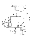
- Fig. 7 depicted in Fig. 7 is an unloading system which does not employ a vacuum device to suck air from the main screw compressor 10.
- a small tank 90 is provided to which lubrication oil can be blown by the main screw compressor 10 when the inlet valve 24 is closed and the valve 76 is open, as shown in Fig. 6.
- the tank 90 is open to atmosphere by way of a conventional air breather 92.
- Oil 94 from the tank 90 is pumped to the air reservoir 12 by a hydraulic pump 96. That also causes the non-return valve 15 to close.
- the air reservoir 12 would also be open to atmosphere.
- a pump 98 would pump oil to the main screw compressor 10. As the main screw compressor 10 blows out oil, it also blows out air, thereby reducing the air density within the main screw compressor 10, making it easier to rotate the screws. Ease of rotation also results from the fact that the main screw compressor 10 acts only against atmospheric pressure, i.e., 1 bar (14.5 psi), as it blows out the oil.
- the compressor 10 is not unloaded to the same extent as in the previously described embodiments wherein a vacuum is established in the main screw compressor 10, the compressor 10 is nevertheless unloaded by an amount sufficient to considerably reduce the power required to operate it.
- the air inlet valve 24 could, if desired, be provided with a small hole drilled therethrough to enable a small amount of air to pass through the valve 24 even when the valve closed, if needed to reduce compressor noise. However, the amount of air that would pass through such a hole is so small that, as defined herein, the air inlet 26 would still be considered as "closed.” It will be appreciated that the present invention enables the power consumption of the motor 18 to be appreciably reduced in a relatively simple and economic manner while continually driving the main screw compressor 10, or while starting-up the motor.
Landscapes
- Engineering & Computer Science (AREA)
- Mechanical Engineering (AREA)
- General Engineering & Computer Science (AREA)
- Applications Or Details Of Rotary Compressors (AREA)
Applications Claiming Priority (3)
| Application Number | Priority Date | Filing Date | Title |
|---|---|---|---|
| US10/147,883 US6860730B2 (en) | 2002-05-20 | 2002-05-20 | Methods and apparatus for unloading a screw compressor |
| US147883 | 2002-05-20 | ||
| PCT/SE2003/000743 WO2003098048A1 (en) | 2002-05-20 | 2003-05-08 | Methods and apparatus for unloading a screw compressor |
Publications (2)
| Publication Number | Publication Date |
|---|---|
| EP1511937A1 EP1511937A1 (en) | 2005-03-09 |
| EP1511937B1 true EP1511937B1 (en) | 2007-04-18 |
Family
ID=29419135
Family Applications (1)
| Application Number | Title | Priority Date | Filing Date |
|---|---|---|---|
| EP03725943A Expired - Lifetime EP1511937B1 (en) | 2002-05-20 | 2003-05-08 | Methods and apparatus for unloading a screw compressor |
Country Status (9)
| Country | Link |
|---|---|
| US (1) | US6860730B2 (cg-RX-API-DMAC10.html) |
| EP (1) | EP1511937B1 (cg-RX-API-DMAC10.html) |
| JP (1) | JP4444818B2 (cg-RX-API-DMAC10.html) |
| CN (1) | CN1656319B (cg-RX-API-DMAC10.html) |
| AT (1) | ATE360146T1 (cg-RX-API-DMAC10.html) |
| AU (1) | AU2003228186B2 (cg-RX-API-DMAC10.html) |
| DE (1) | DE60313320T2 (cg-RX-API-DMAC10.html) |
| WO (1) | WO2003098048A1 (cg-RX-API-DMAC10.html) |
| ZA (1) | ZA200409299B (cg-RX-API-DMAC10.html) |
Families Citing this family (14)
| Publication number | Priority date | Publication date | Assignee | Title |
|---|---|---|---|---|
| CA2071577A1 (en) * | 1991-06-21 | 1992-12-22 | Gerald L. Dawson | Electronic combination lock with high security features |
| US6981855B2 (en) * | 2002-09-30 | 2006-01-03 | Sandvik Ab | Drilling rig having a compact compressor/pump assembly |
| US7909026B2 (en) * | 2008-04-16 | 2011-03-22 | Gm Global Technology Operations, Inc. | Servo-actuated supercharger operating mechanism |
| ITPR20090054A1 (it) * | 2009-07-10 | 2011-01-11 | Robuschi S P A | Compressore a vite a secco |
| US8646549B2 (en) * | 2009-10-08 | 2014-02-11 | Atlas Copco Drilling Solutions Llc | Drilling machine power pack which includes a clutch |
| EP2561181A1 (en) | 2010-04-20 | 2013-02-27 | Sandvik Intellectual Property AB | Air compressor system and method of operation |
| US10941770B2 (en) | 2010-07-20 | 2021-03-09 | Trane International Inc. | Variable capacity screw compressor and method |
| US9145877B2 (en) | 2011-11-22 | 2015-09-29 | Thermo King Corporation | Compressor unloading device |
| WO2014047377A2 (en) * | 2012-09-21 | 2014-03-27 | Sandvik Surface Mining | Method and apparatus for decompressing a compressor |
| KR102330933B1 (ko) * | 2014-01-31 | 2021-11-24 | 후루까와 로크 드릴 가부시끼가이샤 | 천공기, 언로드 제어용 프로그램 |
| DE102015111287B4 (de) | 2015-07-13 | 2018-04-26 | Gardner Denver Deutschland Gmbh | Kompressor und Verfahren zu dessen Drehzahlsteuerung |
| CA3179438A1 (en) | 2015-10-30 | 2017-05-04 | Gardner Denver, Inc. | Complex screw rotors |
| CA3016521A1 (en) * | 2017-09-06 | 2019-03-06 | Joy Global Surface Mining Inc | Lubrication system for a compressor |
| AU2021202410A1 (en) | 2020-04-21 | 2021-11-11 | Joy Global Surface Mining Inc | Lubrication system for a compressor |
Family Cites Families (11)
| Publication number | Priority date | Publication date | Assignee | Title |
|---|---|---|---|---|
| US3708024A (en) | 1971-03-10 | 1973-01-02 | Sanderson Cyclone Drill Co | Drilling machine |
| US3759636A (en) * | 1972-03-13 | 1973-09-18 | Dunham Busa Inc | Composite variable oil pressure relief and compressor unload valve assembly |
| US3913346A (en) * | 1974-05-30 | 1975-10-21 | Dunham Bush Inc | Liquid refrigerant injection system for hermetic electric motor driven helical screw compressor |
| US3947078A (en) | 1975-04-24 | 1976-03-30 | Sullair Corporation | Rotary screw machine with rotor thrust load balancing |
| JPS5799291A (en) * | 1980-12-10 | 1982-06-19 | Hitachi Ltd | Volume controller for screw compressor |
| SE424760B (sv) | 1980-12-12 | 1982-08-09 | Sullair Tech Ab | Forfarande vid en oljeinsprutad skruvkompressor for balansering av axialkrafter hos atminstone en av kompressorns rotorer, for tetning av spalterna mellan rotorhus och rotorernas axlar, samt for kylning och smorjning .. |
| EP0130662B1 (en) * | 1983-04-08 | 1988-06-29 | Cash Engineering Co. Pty. Limited | Compressor control system |
| US5497841A (en) * | 1991-03-14 | 1996-03-12 | William Mohlenhoff | Methods for coring a masonry wall |
| FI87830C (fi) * | 1991-05-23 | 1993-02-25 | Tamrock Oy | Foerfarande och anordning foer styrande av en bergborrmaskins luftmatning |
| JP3429999B2 (ja) * | 1998-01-19 | 2003-07-28 | 株式会社神戸製鋼所 | スクリュ圧縮機の吐出圧力制御方法 |
| JP3837278B2 (ja) * | 2000-08-10 | 2006-10-25 | 株式会社神戸製鋼所 | 圧縮機の運転方法 |
-
2002
- 2002-05-20 US US10/147,883 patent/US6860730B2/en not_active Expired - Lifetime
-
2003
- 2003-05-08 WO PCT/SE2003/000743 patent/WO2003098048A1/en not_active Ceased
- 2003-05-08 JP JP2004505544A patent/JP4444818B2/ja not_active Expired - Lifetime
- 2003-05-08 CN CN03811599.9A patent/CN1656319B/zh not_active Expired - Lifetime
- 2003-05-08 EP EP03725943A patent/EP1511937B1/en not_active Expired - Lifetime
- 2003-05-08 AU AU2003228186A patent/AU2003228186B2/en not_active Expired
- 2003-05-08 DE DE60313320T patent/DE60313320T2/de not_active Expired - Lifetime
- 2003-05-08 AT AT03725943T patent/ATE360146T1/de not_active IP Right Cessation
-
2004
- 2004-11-18 ZA ZA2004/09299A patent/ZA200409299B/en unknown
Also Published As
| Publication number | Publication date |
|---|---|
| CN1656319B (zh) | 2011-04-13 |
| DE60313320D1 (de) | 2007-05-31 |
| AU2003228186B2 (en) | 2009-05-07 |
| WO2003098048A1 (en) | 2003-11-27 |
| US6860730B2 (en) | 2005-03-01 |
| JP4444818B2 (ja) | 2010-03-31 |
| US20030215338A1 (en) | 2003-11-20 |
| AU2003228186A1 (en) | 2003-12-02 |
| CN1656319A (zh) | 2005-08-17 |
| DE60313320T2 (de) | 2007-12-20 |
| EP1511937A1 (en) | 2005-03-09 |
| JP2005526214A (ja) | 2005-09-02 |
| ATE360146T1 (de) | 2007-05-15 |
| ZA200409299B (en) | 2005-08-31 |
Similar Documents
| Publication | Publication Date | Title |
|---|---|---|
| AU2003228186B2 (en) | Methods and apparatus for unloading a screw compressor | |
| CN102859108B (zh) | 空气压缩机系统及操作方法 | |
| US11441369B2 (en) | Fluid coupling drive system for a drill rig air compressor | |
| US20040173379A1 (en) | Hydraulically-operated control system for a screw compressor | |
| EP2917578B1 (en) | Method and apparatus for decompressing a compressor | |
| FI87830B (fi) | Foerfarande och anordning foer styrande av en bergborrmaskins luftmatning | |
| US7165952B2 (en) | Hydraulically driven oil recovery system | |
| US4668251A (en) | Mud pump degassing and supercharging apparatus | |
| CN215565866U (zh) | 液压抽油机 | |
| AU2011293946B2 (en) | Method and system for controlling a power source at a rock drilling apparatus and rock drilling apparatus | |
| US11680588B2 (en) | Lubrication system for a compressor | |
| CN110185052A (zh) | 一种伺服驱动器应用于基坑降水的方法及系统 | |
| AU2013317928B2 (en) | Method and apparatus for decompressing a compressor | |
| CN210622776U (zh) | 一种套管气回收并带动原油抽采的增产节能装置 | |
| CN1673534A (zh) | 井下动力直接驱动柱塞式抽油泵 | |
| CN201212357Y (zh) | 一种泵吸式反循环钻井机 | |
| CN1278010C (zh) | 一种液动湿式钻 | |
| CN121557155A (zh) | 集破碎和冲击旋转钻进于一体的卧底机液压控制系统 |
Legal Events
| Date | Code | Title | Description |
|---|---|---|---|
| PUAI | Public reference made under article 153(3) epc to a published international application that has entered the european phase |
Free format text: ORIGINAL CODE: 0009012 |
|
| 17P | Request for examination filed |
Effective date: 20041112 |
|
| AK | Designated contracting states |
Kind code of ref document: A1 Designated state(s): AT BE BG CH CY CZ DE DK EE ES FI FR GB GR HU IE IT LI LU MC NL PT RO SE SI SK TR |
|
| AX | Request for extension of the european patent |
Extension state: AL LT LV MK |
|
| RAP1 | Party data changed (applicant data changed or rights of an application transferred) |
Owner name: SANDVIK INTELLECTUAL PROPERTY HB |
|
| RAP1 | Party data changed (applicant data changed or rights of an application transferred) |
Owner name: SANDVIK INTELLECTUAL PROPERTY AB |
|
| DAX | Request for extension of the european patent (deleted) | ||
| GRAP | Despatch of communication of intention to grant a patent |
Free format text: ORIGINAL CODE: EPIDOSNIGR1 |
|
| RIC1 | Information provided on ipc code assigned before grant |
Ipc: E21B 21/14 20060101ALI20061115BHEP Ipc: F04C 28/00 20060101AFI20061115BHEP Ipc: F04C 18/16 20060101ALI20061115BHEP |
|
| GRAS | Grant fee paid |
Free format text: ORIGINAL CODE: EPIDOSNIGR3 |
|
| GRAA | (expected) grant |
Free format text: ORIGINAL CODE: 0009210 |
|
| AK | Designated contracting states |
Kind code of ref document: B1 Designated state(s): AT BE BG CH CY CZ DE DK EE ES FI FR GB GR HU IE IT LI LU MC NL PT RO SE SI SK TR |
|
| PG25 | Lapsed in a contracting state [announced via postgrant information from national office to epo] |
Ref country code: LI Free format text: LAPSE BECAUSE OF FAILURE TO SUBMIT A TRANSLATION OF THE DESCRIPTION OR TO PAY THE FEE WITHIN THE PRESCRIBED TIME-LIMIT Effective date: 20070418 Ref country code: SI Free format text: LAPSE BECAUSE OF FAILURE TO SUBMIT A TRANSLATION OF THE DESCRIPTION OR TO PAY THE FEE WITHIN THE PRESCRIBED TIME-LIMIT Effective date: 20070418 Ref country code: CH Free format text: LAPSE BECAUSE OF FAILURE TO SUBMIT A TRANSLATION OF THE DESCRIPTION OR TO PAY THE FEE WITHIN THE PRESCRIBED TIME-LIMIT Effective date: 20070418 |
|
| REG | Reference to a national code |
Ref country code: CH Ref legal event code: EP |
|
| REG | Reference to a national code |
Ref country code: IE Ref legal event code: FG4D |
|
| REF | Corresponds to: |
Ref document number: 60313320 Country of ref document: DE Date of ref document: 20070531 Kind code of ref document: P |
|
| REG | Reference to a national code |
Ref country code: SE Ref legal event code: TRGR |
|
| PG25 | Lapsed in a contracting state [announced via postgrant information from national office to epo] |
Ref country code: ES Free format text: LAPSE BECAUSE OF FAILURE TO SUBMIT A TRANSLATION OF THE DESCRIPTION OR TO PAY THE FEE WITHIN THE PRESCRIBED TIME-LIMIT Effective date: 20070729 |
|
| PG25 | Lapsed in a contracting state [announced via postgrant information from national office to epo] |
Ref country code: PT Free format text: LAPSE BECAUSE OF FAILURE TO SUBMIT A TRANSLATION OF THE DESCRIPTION OR TO PAY THE FEE WITHIN THE PRESCRIBED TIME-LIMIT Effective date: 20070918 |
|
| ET | Fr: translation filed | ||
| REG | Reference to a national code |
Ref country code: CH Ref legal event code: PL |
|
| NLV1 | Nl: lapsed or annulled due to failure to fulfill the requirements of art. 29p and 29m of the patents act | ||
| PG25 | Lapsed in a contracting state [announced via postgrant information from national office to epo] |
Ref country code: AT Free format text: LAPSE BECAUSE OF FAILURE TO SUBMIT A TRANSLATION OF THE DESCRIPTION OR TO PAY THE FEE WITHIN THE PRESCRIBED TIME-LIMIT Effective date: 20070418 |
|
| PG25 | Lapsed in a contracting state [announced via postgrant information from national office to epo] |
Ref country code: BE Free format text: LAPSE BECAUSE OF FAILURE TO SUBMIT A TRANSLATION OF THE DESCRIPTION OR TO PAY THE FEE WITHIN THE PRESCRIBED TIME-LIMIT Effective date: 20070418 |
|
| PG25 | Lapsed in a contracting state [announced via postgrant information from national office to epo] |
Ref country code: DK Free format text: LAPSE BECAUSE OF FAILURE TO SUBMIT A TRANSLATION OF THE DESCRIPTION OR TO PAY THE FEE WITHIN THE PRESCRIBED TIME-LIMIT Effective date: 20070418 Ref country code: BG Free format text: LAPSE BECAUSE OF FAILURE TO SUBMIT A TRANSLATION OF THE DESCRIPTION OR TO PAY THE FEE WITHIN THE PRESCRIBED TIME-LIMIT Effective date: 20070718 Ref country code: NL Free format text: LAPSE BECAUSE OF FAILURE TO SUBMIT A TRANSLATION OF THE DESCRIPTION OR TO PAY THE FEE WITHIN THE PRESCRIBED TIME-LIMIT Effective date: 20070418 Ref country code: MC Free format text: LAPSE BECAUSE OF NON-PAYMENT OF DUE FEES Effective date: 20070531 Ref country code: CZ Free format text: LAPSE BECAUSE OF FAILURE TO SUBMIT A TRANSLATION OF THE DESCRIPTION OR TO PAY THE FEE WITHIN THE PRESCRIBED TIME-LIMIT Effective date: 20070418 |
|
| PLBE | No opposition filed within time limit |
Free format text: ORIGINAL CODE: 0009261 |
|
| STAA | Information on the status of an ep patent application or granted ep patent |
Free format text: STATUS: NO OPPOSITION FILED WITHIN TIME LIMIT |
|
| PG25 | Lapsed in a contracting state [announced via postgrant information from national office to epo] |
Ref country code: SK Free format text: LAPSE BECAUSE OF FAILURE TO SUBMIT A TRANSLATION OF THE DESCRIPTION OR TO PAY THE FEE WITHIN THE PRESCRIBED TIME-LIMIT Effective date: 20070418 |
|
| 26N | No opposition filed |
Effective date: 20080121 |
|
| GBPC | Gb: european patent ceased through non-payment of renewal fee |
Effective date: 20070718 |
|
| PG25 | Lapsed in a contracting state [announced via postgrant information from national office to epo] |
Ref country code: GR Free format text: LAPSE BECAUSE OF FAILURE TO SUBMIT A TRANSLATION OF THE DESCRIPTION OR TO PAY THE FEE WITHIN THE PRESCRIBED TIME-LIMIT Effective date: 20070719 Ref country code: IT Free format text: LAPSE BECAUSE OF FAILURE TO SUBMIT A TRANSLATION OF THE DESCRIPTION OR TO PAY THE FEE WITHIN THE PRESCRIBED TIME-LIMIT Effective date: 20070418 |
|
| PG25 | Lapsed in a contracting state [announced via postgrant information from national office to epo] |
Ref country code: RO Free format text: LAPSE BECAUSE OF FAILURE TO SUBMIT A TRANSLATION OF THE DESCRIPTION OR TO PAY THE FEE WITHIN THE PRESCRIBED TIME-LIMIT Effective date: 20070418 Ref country code: GB Free format text: LAPSE BECAUSE OF NON-PAYMENT OF DUE FEES Effective date: 20070718 Ref country code: IE Free format text: LAPSE BECAUSE OF NON-PAYMENT OF DUE FEES Effective date: 20070508 |
|
| PG25 | Lapsed in a contracting state [announced via postgrant information from national office to epo] |
Ref country code: EE Free format text: LAPSE BECAUSE OF FAILURE TO SUBMIT A TRANSLATION OF THE DESCRIPTION OR TO PAY THE FEE WITHIN THE PRESCRIBED TIME-LIMIT Effective date: 20070418 |
|
| PG25 | Lapsed in a contracting state [announced via postgrant information from national office to epo] |
Ref country code: CY Free format text: LAPSE BECAUSE OF FAILURE TO SUBMIT A TRANSLATION OF THE DESCRIPTION OR TO PAY THE FEE WITHIN THE PRESCRIBED TIME-LIMIT Effective date: 20070418 |
|
| PG25 | Lapsed in a contracting state [announced via postgrant information from national office to epo] |
Ref country code: LU Free format text: LAPSE BECAUSE OF NON-PAYMENT OF DUE FEES Effective date: 20070508 |
|
| PG25 | Lapsed in a contracting state [announced via postgrant information from national office to epo] |
Ref country code: HU Free format text: LAPSE BECAUSE OF FAILURE TO SUBMIT A TRANSLATION OF THE DESCRIPTION OR TO PAY THE FEE WITHIN THE PRESCRIBED TIME-LIMIT Effective date: 20071019 Ref country code: TR Free format text: LAPSE BECAUSE OF FAILURE TO SUBMIT A TRANSLATION OF THE DESCRIPTION OR TO PAY THE FEE WITHIN THE PRESCRIBED TIME-LIMIT Effective date: 20070418 |
|
| REG | Reference to a national code |
Ref country code: FR Ref legal event code: PLFP Year of fee payment: 14 |
|
| REG | Reference to a national code |
Ref country code: FR Ref legal event code: PLFP Year of fee payment: 15 |
|
| REG | Reference to a national code |
Ref country code: FR Ref legal event code: PLFP Year of fee payment: 16 |
|
| PGFP | Annual fee paid to national office [announced via postgrant information from national office to epo] |
Ref country code: SE Payment date: 20220411 Year of fee payment: 20 Ref country code: FR Payment date: 20220422 Year of fee payment: 20 Ref country code: DE Payment date: 20220406 Year of fee payment: 20 |
|
| PGFP | Annual fee paid to national office [announced via postgrant information from national office to epo] |
Ref country code: FI Payment date: 20220509 Year of fee payment: 20 |
|
| REG | Reference to a national code |
Ref country code: DE Ref legal event code: R071 Ref document number: 60313320 Country of ref document: DE |
|
| REG | Reference to a national code |
Ref country code: SE Ref legal event code: EUG |