EP1511911B1 - Gewindeverbindung für ein bohrgestänge zum schlaggesteinsbohren - Google Patents
Gewindeverbindung für ein bohrgestänge zum schlaggesteinsbohren Download PDFInfo
- Publication number
- EP1511911B1 EP1511911B1 EP03723605.6A EP03723605A EP1511911B1 EP 1511911 B1 EP1511911 B1 EP 1511911B1 EP 03723605 A EP03723605 A EP 03723605A EP 1511911 B1 EP1511911 B1 EP 1511911B1
- Authority
- EP
- European Patent Office
- Prior art keywords
- threads
- thread
- drill
- male
- screw
- Prior art date
- Legal status (The legal status is an assumption and is not a legal conclusion. Google has not performed a legal analysis and makes no representation as to the accuracy of the status listed.)
- Expired - Lifetime
Links
- 238000005553 drilling Methods 0.000 title claims description 6
- 238000009527 percussion Methods 0.000 claims description 4
- 239000011435 rock Substances 0.000 claims description 4
- 238000005452 bending Methods 0.000 description 1
- 230000000694 effects Effects 0.000 description 1
- 239000000463 material Substances 0.000 description 1
- 238000004904 shortening Methods 0.000 description 1
Images
Classifications
-
- E—FIXED CONSTRUCTIONS
- E21—EARTH OR ROCK DRILLING; MINING
- E21B—EARTH OR ROCK DRILLING; OBTAINING OIL, GAS, WATER, SOLUBLE OR MELTABLE MATERIALS OR A SLURRY OF MINERALS FROM WELLS
- E21B17/00—Drilling rods or pipes; Flexible drill strings; Kellies; Drill collars; Sucker rods; Cables; Casings; Tubings
- E21B17/02—Couplings; joints
- E21B17/04—Couplings; joints between rod or the like and bit or between rod and rod or the like
- E21B17/042—Threaded
Definitions
- the present invention relates to a screw joint for a drill run for percussion rock drilling, a drill rod and a drill bit therefor.
- Screw joints of this nature are used to join together drill string elements, such as a drill bit, one or more drill strings and a shank adapter.
- the screw joints include mutually co-acting male and female screw threads where an external male thread on a component element is screwed to an internal female thread on a co-acting element, so as to join said elements together.
- Swedish Patent Specification 515518 teaches a screw joint of the aforesaid kind in which the male and the female threads are conical and the tops and bottoms of the thread profiles have a radius of curvature that is greater than 30% of the thread pitch.
- Such a screw thread is referred to typically as a rope thread.
- a threaded joint for drill pipes is described in US Patent No. 3,129,963 .
- the joint is said to be broken with a minimum amount of torque and at the same time provide a tight and sturdy joint.
- the threads have a cone angle of 14° to 18° and the flanks subtend an angle of approximately 25° to 50° to a plane extending through an adjacent root and normal to the axial centre line of the members having the threads.
- an object of the invention is to provide a novel screw joint with which the aforesaid problems are eliminated, so as to enable the novel screw joint to be used also with drill runs or strings of coarser dimensions.
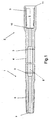
- Figure 1 is a broken longitudinally sectioned view of a drill rod, showing in particular both ends of the rod.
- the male end 1 and the female end 2 are connected, suitably welded at 3, to an intermediate element 4 so as to obtain an elongate drill rod.
- a drill rod of this kind may typically have a length of 6 metres.
- a drill string may consist of a number of such rods that have been screwed together with the aid of respective screw threads.
- the drill string includes a drill bit at one end and a shank adapter at the other end, which are also joined to the drill rods by means of corresponding screw threads.
- the male end 1 is provided with an external screw thread or male thread 5. It will also be seen from the figure that the male thread is conical and is inclined towards the centre axis 6 (shown in chain lines) of the drill rod.
- the male end 1 has an end surface 7 that can be used as a stop surface, as described in more detail below.
- the female end 2 includes an internally extending hole 8 in which the male end 1 of another drill rod can be received.
- the hole 8 has an internal thread, or female thread 9, which is intended to be screwed together with the male thread 5 of another element to be connected to the element currying the female thread.
- the female thread is therefore also slightly conical and has the same angle of inclination towards the centre axis 6 (shown in chain lines) of the drill rod.
- Located at the bottom of the hole 8 is an abutment surface against with the end surface 7 of the male part 1 can bottom when screwing two elements together.
- the female part 2 may be provided at its free end with a generally cylindrical contact surface 11 that surrounds the mouth of the hole 8.
- the male part 1 may then be provided with a corresponding contact flange at a distance from the end of the male part that is shorter than the depth of the hole 8, so that the male and female parts will reach end positions as a result of the contact between the contact surface and the contact flange, instead of the end surface 7 of the male part coming into contact with the abutment surface 10 of the female part.
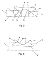
- Figure 2 shows part of an internal thread 9 of a female part 2.
- the flanks or edges 9a, 9b of the thread 9 define angles ⁇ and ⁇ , respectively, with the line 12 tangential to the apices 9c of the threads.
- the difference between the angles, ⁇ - ⁇ , is equal to two times the angle ⁇ between the line 12 and the centre line 6.
- This means that the flanks 9a, 9b define the same angle ⁇ in relation to the centre line 6.
- the flanks are also symmetrical with a straight central line between the flanks that also is perpendicular to the centre line 6.
- flanks it is not necessary that the angles of the flanks to the centre line are exactly the same, but it is preferred that the flanks define essentially the same angle to the centre line 6.
- Figure 3 shows a view similar to that shown in Figure 2 , but in this case showing a part of the outer thread 5 of a male part 1. Also this thread 5 defines flanks or edges 5a and 5b, that define angles ⁇ and ⁇ , respectively, with the line 13 tangential to the apices 5c of the threads. The difference between the angles, ⁇ - ⁇ , is equal to two times the angle ⁇ between the line 13 and the centre line 6. This also means that the flanks 5a, 5b define the same angle in relation to the centre line 6 for the same reason as that mentioned above.
- the thread flank angles ⁇ , ⁇ are smaller than 45°, preferably between 30 and 40°, in relation to the respective lines 12, 13 that are tangential to the apices of the flanks or edges of the thread.
- the cone angle is smaller than 7°, preferably about 4°. With a cone angle of 4°, the angle ⁇ in the figures will thus be 2°.
- An inventive thread design reduces the risk of the drill string breaking under the bending stresses to which it is subjected in the drill hole.
- the conical configuration of the screw thread enables the material thickness to be increased in the inner parts of respective threads, with a corresponding reduction in the risk of a breakage or fracture occurring.
- the screw joint according to the present invention can be readily unscrewed when the drill string or drill run is withdrawn from the drill hole, but is nevertheless sufficiently stable to ensure that the screw threads will not loosen in the hole.
- the screw joints are constructed so that the drill strings have a female thread at one end and a male thread at the other end.
- inventive screw joint can also be used in conjunction with splicing sleeves, although screw joints that are fully integrated in the drill strings are preferred since this eliminates the risk of damage due to loosening splicing sleeves.
Landscapes
- Engineering & Computer Science (AREA)
- Life Sciences & Earth Sciences (AREA)
- Geology (AREA)
- Mining & Mineral Resources (AREA)
- Mechanical Engineering (AREA)
- Physics & Mathematics (AREA)
- Environmental & Geological Engineering (AREA)
- Fluid Mechanics (AREA)
- General Life Sciences & Earth Sciences (AREA)
- Geochemistry & Mineralogy (AREA)
- Earth Drilling (AREA)
- Surgical Instruments (AREA)
Claims (9)
- Schraubverbindung für einen Bohrstrang oder ein Bohrgestänge zum Gesteinsschlagbohren, die männliche und weibliche Schraubgewinde (5,9) an zur Bildung eines Bohrgestänges zu verbindenden Elementen (1,2) aufweist, dadurch gekennzeichnet, dass das männliche Gewinde (5) und dass weibliche Gewinde (9) eine Trapezform besitzen, dass die Gewinde eine Konusneigung über die Länge der Gewinde mit einem Konuswinkel kleiner als 7° aufweisen und dass die Flankenwinkel (α, β) zwischen den Flanken der Gewinde und der Linie (13;12), die tangential zu den Scheiteln (5c; 9c) der Gewinde liegt, kleiner als 45° sind.
- Schraubverbindung nach Anspruch 1, dadurch gekennzeichnet, dass der Konuswinkel ungefähr 4° beträgt.
- Schraubverbindung nach Anspruch 1 oder 2, dadurch gekennzeichnet, dass die Flanken (5a,5b;9a,9b) der Gewinde im wesentlichen im gleichen Winkel (ϕ) zu der Mittellinie (6) der Gewinde (5,9) stehen.
- Schraubverbindung nach einem der Ansprüche 1 bis 3, dadurch gekennzeichnet, dass die Flankenwinkel (α,β) im Bereich von 30° bis 40° liegen.
- Schraubverbindung nach einem der vorhergehenden Ansprüche, dadurch gekennzeichnet, dass die Bohrstangen, bei welchem die Schraubverbindung eingesetzt ist, ein männliches Schraubgewinde (5) an einem Ende (1) und ein weibliches Schraubgewinde (9) an dem anderen Ende (2) besitzen.
- Bohrstange zum Gesteinsschagbohren, bei welcher die Bohrstange an einem Ende mit einem männlichen Gewinde (5) und an dem anderen Ende mit einem weiblichen Gewinde (9) versehen ist, dadurch gekennzeichnet, dass das männliche Gewinde und das weibliche Gewinde eine Trapezform besitzen, dass die Gewinde einer Konusneigung über die Länge der Gewinde mit einem Konuswinkel kleiner als 7° besitzen und dass die Flankenwinkel (α, β) zwischen den Flanken der Gewinde und der Linie (13;12) die tangential zu den Scheiteln (5c;9c) der Gewinde liegen, kleiner als 45° sind.
- Bohrstange nach Anspruch 6, dadurch gekennzeichnet, dass der Konuswinkel der Gewinde ungefähr 4° beträgt.
- Bohreinsatz für einen Bohrstrang oder ein Bohrgestänge zum Gesteinsschlagbohren, wobei der Bohreinsatz entweder ein männliches Schraubgewinde (5) oder ein weibliches Schraubgewinde (9) aufweist, um das Verbinden des Bohreinsatzes mit einer Bohrstange mit einem entsprechenden Schraubgewinde zu ermöglichen, dadurch gekennzeichnet, dass das Schraubengewinde an dem Bohreinsatz eine Trapezform und eine konische Neigung über die Länge des Gewindes mit einem Konuswinkel von weniger als 7° besitzt und das die Flankenwinkel (α, β) zwischen den Flanken der Gewinde und der Linie (13;12) die tangential zu den Scheiteln (5c;9c) der Gewinde liegen, kleiner als 45° sind.
- Bohreinsatz nach Anspruch 8, dadurch gekennzeichnet, dass der Konuswinkel des Gewindes ungefähr 4° beträgt.
Applications Claiming Priority (3)
| Application Number | Priority Date | Filing Date | Title |
|---|---|---|---|
| SE0201530 | 2002-05-22 | ||
| SE0201530A SE524155C2 (sv) | 2002-05-22 | 2002-05-22 | Gängförband för borrsträng för slående bergborrning |
| PCT/SE2003/000752 WO2003097991A1 (en) | 2002-05-22 | 2003-05-09 | A thread joint for a drill string for percussive rock-drilling |
Publications (2)
| Publication Number | Publication Date |
|---|---|
| EP1511911A1 EP1511911A1 (de) | 2005-03-09 |
| EP1511911B1 true EP1511911B1 (de) | 2014-11-19 |
Family
ID=20287925
Family Applications (1)
| Application Number | Title | Priority Date | Filing Date |
|---|---|---|---|
| EP03723605.6A Expired - Lifetime EP1511911B1 (de) | 2002-05-22 | 2003-05-09 | Gewindeverbindung für ein bohrgestänge zum schlaggesteinsbohren |
Country Status (13)
| Country | Link |
|---|---|
| US (1) | US8066307B2 (de) |
| EP (1) | EP1511911B1 (de) |
| JP (1) | JP4083738B2 (de) |
| KR (1) | KR100987419B1 (de) |
| CN (2) | CN1656297A (de) |
| AU (2) | AU2003230532A1 (de) |
| CA (1) | CA2484540C (de) |
| MX (1) | MXPA04010876A (de) |
| NO (1) | NO333770B1 (de) |
| RU (1) | RU2004137496A (de) |
| SE (1) | SE524155C2 (de) |
| WO (1) | WO2003097991A1 (de) |
| ZA (1) | ZA200408790B (de) |
Cited By (2)
| Publication number | Priority date | Publication date | Assignee | Title |
|---|---|---|---|---|
| EP3141689B1 (de) | 2015-09-11 | 2019-12-04 | Sysbohr GmbH Bohrtechnik für den Spezialtiefbau | Gewindeverbindung und bohrgestänge mit gewindeverbindung |
| EP3819458A1 (de) | 2019-11-08 | 2021-05-12 | Sandvik Mining and Construction Tools AB | Verstärkte buchsenkopplung für schlagbohrgestänge |
Families Citing this family (13)
| Publication number | Priority date | Publication date | Assignee | Title |
|---|---|---|---|---|
| SE524322C2 (sv) * | 2002-09-24 | 2004-07-27 | Sandvik Ab | Borrstång och metod för att tillverka denna |
| SE0701371L (sv) * | 2007-06-05 | 2008-03-11 | Sandvik Intellectual Property | Bergborrutrustning samt hon- och handelar därtill |
| SE535814C2 (sv) | 2011-05-20 | 2013-01-02 | Atlas Copco Secoroc Ab | Gänganordning, gängförband samt borrsträngskomponent för slående bergborrning |
| US10145182B2 (en) * | 2012-11-29 | 2018-12-04 | Tuboscope Vetco (France) Sas | Landing pipe |
| US9643262B2 (en) | 2013-07-25 | 2017-05-09 | Kennametal Inc. | Coupling mechanism for cutting tool |
| US9643264B2 (en) | 2013-07-25 | 2017-05-09 | Kennametal Inc. | Coupling mechanism for cutting tool |
| US9889509B2 (en) | 2014-05-05 | 2018-02-13 | Kennametal Inc. | Cutter heads with improved coupling |
| PT3536894T (pt) * | 2018-03-09 | 2020-11-19 | Sandvik Mining And Construction Tools Ab | Acoplamento para ligar elementos tubulares de fundo de furo |
| PL3536893T3 (pl) * | 2018-03-09 | 2021-03-08 | Sandvik Mining And Construction Tools Ab | Połączenie do wiercenia udarowego |
| US11199056B2 (en) | 2019-02-06 | 2021-12-14 | James Jing Yao | Threaded coupling for percussion drill bit |
| CN110821936A (zh) * | 2019-10-28 | 2020-02-21 | 洛阳金鹭硬质合金工具有限公司 | 一种高性能锥度螺纹 |
| MX2023010038A (es) | 2021-02-26 | 2023-09-11 | Sandvik Mining And Construction Tools Ab | Acoplamiento para conectar tubos de fondo de pozo con distribucion de tensiones mejorada. |
| WO2022180226A2 (en) | 2021-02-26 | 2022-09-01 | Sandvik Mining And Construction Tools Ab | Coupling for connecting downhole tubulars with reduced stress |
Citations (1)
| Publication number | Priority date | Publication date | Assignee | Title |
|---|---|---|---|---|
| US20020074797A1 (en) * | 2000-11-30 | 2002-06-20 | Per-Olof Liljebrand | Thread joint for percussive drilling and parts therefor |
Family Cites Families (15)
| Publication number | Priority date | Publication date | Assignee | Title |
|---|---|---|---|---|
| US3129963A (en) * | 1960-06-30 | 1964-04-21 | Robbins Machine & Mfg Co | Low release torque threaded joint |
| SE336316B (de) * | 1969-10-22 | 1971-07-05 | Fagersta Bruks Ab | |
| SE401232B (sv) * | 1970-05-04 | 1978-04-24 | Sandvik Ab | Gengad forbindning for slagborrstenger |
| SE469602B (sv) * | 1985-04-04 | 1993-08-02 | Sandvik Ab | Skarvgaenga foer slagborrning |
| US5169183A (en) * | 1987-05-12 | 1992-12-08 | Diamant Boart Stratabit S.A. | Threaded joint for drill rod elements |
| IT1224745B (it) * | 1988-10-03 | 1990-10-18 | Dalmine Spa | Giunto a tenuta ermetica metallica per tubi |
| USH1329H (en) * | 1992-04-28 | 1994-07-05 | Exxon Production Research Company | Drill collar connections |
| AUPO445897A0 (en) * | 1997-01-06 | 1997-01-30 | Boart Longyear Inc. | Straight hole drilling system |
| US6030004A (en) * | 1997-12-08 | 2000-02-29 | Shaw Industries | High torque threaded tool joint for drill pipe and other drill stem components |
| SE514137C2 (sv) * | 1998-03-24 | 2001-01-08 | Sandvik Ab | Gängförband för slående borrning, han- och hondel för att ingå i ett gängförband för slående borrning samt metod för att tillverka en produkt med en gänga för att ingå i ett gängförband för slående borrning |
| GB2340148B (en) | 1998-07-30 | 2002-12-31 | Boart Longyear Ltd | Tube rod |
| SE515518C2 (sv) | 1998-09-28 | 2001-08-20 | Uniroc Ab | Gängförband för borrsträng för slående bergborrning |
| SE516651C2 (sv) | 1999-11-26 | 2002-02-05 | Sandvik Ab | Gängförband för slående borrning, en handel och en hondel |
| SE0003916L (sv) * | 2000-10-27 | 2002-02-19 | Sandvik Ab | Styrrör för mekanisk hantering i en rigg för bergborrning samt borrsträng för mekanisk hantering |
| US7455329B2 (en) * | 2004-01-29 | 2008-11-25 | Grant Prideco, L.P. | Fast make-up fatigue resistant rotary shouldered connection |
-
2002
- 2002-05-22 SE SE0201530A patent/SE524155C2/sv unknown
-
2003
- 2003-05-09 CN CNA038117169A patent/CN1656297A/zh active Pending
- 2003-05-09 AU AU2003230532A patent/AU2003230532A1/en not_active Abandoned
- 2003-05-09 RU RU2004137496/03A patent/RU2004137496A/ru not_active Application Discontinuation
- 2003-05-09 JP JP2004505493A patent/JP4083738B2/ja not_active Expired - Lifetime
- 2003-05-09 CA CA2484540A patent/CA2484540C/en not_active Expired - Lifetime
- 2003-05-09 MX MXPA04010876A patent/MXPA04010876A/es not_active Application Discontinuation
- 2003-05-09 WO PCT/SE2003/000752 patent/WO2003097991A1/en not_active Ceased
- 2003-05-09 KR KR1020047018870A patent/KR100987419B1/ko not_active Expired - Lifetime
- 2003-05-09 US US10/514,953 patent/US8066307B2/en not_active Expired - Lifetime
- 2003-05-09 CN CN2009101659636A patent/CN101644143B/zh not_active Expired - Lifetime
- 2003-05-09 EP EP03723605.6A patent/EP1511911B1/de not_active Expired - Lifetime
-
2004
- 2004-10-29 ZA ZA200408790A patent/ZA200408790B/en unknown
- 2004-11-09 NO NO20044874A patent/NO333770B1/no not_active IP Right Cessation
-
2009
- 2009-02-17 AU AU2009200611A patent/AU2009200611B2/en not_active Expired
Patent Citations (1)
| Publication number | Priority date | Publication date | Assignee | Title |
|---|---|---|---|---|
| US20020074797A1 (en) * | 2000-11-30 | 2002-06-20 | Per-Olof Liljebrand | Thread joint for percussive drilling and parts therefor |
Cited By (3)
| Publication number | Priority date | Publication date | Assignee | Title |
|---|---|---|---|---|
| EP3141689B1 (de) | 2015-09-11 | 2019-12-04 | Sysbohr GmbH Bohrtechnik für den Spezialtiefbau | Gewindeverbindung und bohrgestänge mit gewindeverbindung |
| EP3819458A1 (de) | 2019-11-08 | 2021-05-12 | Sandvik Mining and Construction Tools AB | Verstärkte buchsenkopplung für schlagbohrgestänge |
| WO2021089727A1 (en) | 2019-11-08 | 2021-05-14 | Sandvik Mining And Construction Tools Ab | Strengthened percussive drill string female coupling |
Also Published As
| Publication number | Publication date |
|---|---|
| EP1511911A1 (de) | 2005-03-09 |
| AU2009200611A1 (en) | 2009-03-05 |
| WO2003097991A1 (en) | 2003-11-27 |
| SE0201530L (sv) | 2003-11-23 |
| AU2009200611B2 (en) | 2010-11-11 |
| RU2004137496A (ru) | 2005-05-27 |
| KR20050016424A (ko) | 2005-02-21 |
| SE0201530D0 (sv) | 2002-05-22 |
| AU2003230532A1 (en) | 2003-12-02 |
| KR100987419B1 (ko) | 2010-10-12 |
| CN101644143A (zh) | 2010-02-10 |
| CA2484540C (en) | 2012-04-03 |
| US8066307B2 (en) | 2011-11-29 |
| CA2484540A1 (en) | 2003-11-27 |
| MXPA04010876A (es) | 2005-07-14 |
| CN101644143B (zh) | 2013-06-12 |
| NO333770B1 (no) | 2013-09-16 |
| NO20044874L (no) | 2004-11-09 |
| US20060118340A1 (en) | 2006-06-08 |
| SE524155C2 (sv) | 2004-07-06 |
| CN1656297A (zh) | 2005-08-17 |
| JP4083738B2 (ja) | 2008-04-30 |
| ZA200408790B (en) | 2005-11-03 |
| JP2005526201A (ja) | 2005-09-02 |
Similar Documents
| Publication | Publication Date | Title |
|---|---|---|
| AU2009200611B2 (en) | A thread joint for a drill string for percussive rock-drilling | |
| US6196598B1 (en) | Straight hole drilling system | |
| EP1127209B1 (de) | Schraubenverbindung eines bohrstrangs zum schlagbohren | |
| US12241313B2 (en) | Connection for percussion drilling | |
| US20240229567A9 (en) | Coupling for connecting downhole tubulars with reduced stress | |
| US11598159B2 (en) | Coupling for connecting downhole tubulars | |
| CA3204022A1 (en) | Coupling for connecting downhole tubulars with improved stress distribution | |
| WO2021255494A1 (en) | Wireline drill rod | |
| CA2303710C (en) | Straight hole drilling system | |
| AU722409B3 (en) | Straight hole drilling system | |
| CA3237881A1 (en) | Thread pitch | |
| WO1997032109A1 (en) | Dual pitch connecting joint | |
| AU4505500A (en) | Straight hole drilling system |
Legal Events
| Date | Code | Title | Description |
|---|---|---|---|
| PUAI | Public reference made under article 153(3) epc to a published international application that has entered the european phase |
Free format text: ORIGINAL CODE: 0009012 |
|
| 17P | Request for examination filed |
Effective date: 20041105 |
|
| AK | Designated contracting states |
Kind code of ref document: A1 Designated state(s): AT BE BG CH CY CZ DE DK EE ES FI FR GB GR HU IE IT LI LU MC NL PT RO SE SI SK TR |
|
| AX | Request for extension of the european patent |
Extension state: AL LT LV MK |
|
| RIN1 | Information on inventor provided before grant (corrected) |
Inventor name: ERICSON, JOHAN Inventor name: WAHLSTROEM, PATRIK |
|
| DAX | Request for extension of the european patent (deleted) | ||
| GRAP | Despatch of communication of intention to grant a patent |
Free format text: ORIGINAL CODE: EPIDOSNIGR1 |
|
| INTG | Intention to grant announced |
Effective date: 20140321 |
|
| GRAP | Despatch of communication of intention to grant a patent |
Free format text: ORIGINAL CODE: EPIDOSNIGR1 |
|
| INTG | Intention to grant announced |
Effective date: 20140611 |
|
| GRAS | Grant fee paid |
Free format text: ORIGINAL CODE: EPIDOSNIGR3 |
|
| GRAA | (expected) grant |
Free format text: ORIGINAL CODE: 0009210 |
|
| AK | Designated contracting states |
Kind code of ref document: B1 Designated state(s): AT BE BG CH CY CZ DE DK EE ES FI FR GB GR HU IE IT LI LU MC NL PT RO SE SI SK TR |
|
| REG | Reference to a national code |
Ref country code: GB Ref legal event code: FG4D |
|
| REG | Reference to a national code |
Ref country code: CH Ref legal event code: EP |
|
| REG | Reference to a national code |
Ref country code: AT Ref legal event code: REF Ref document number: 697158 Country of ref document: AT Kind code of ref document: T Effective date: 20141215 |
|
| REG | Reference to a national code |
Ref country code: IE Ref legal event code: FG4D |
|
| REG | Reference to a national code |
Ref country code: DE Ref legal event code: R096 Ref document number: 60347003 Country of ref document: DE Effective date: 20141231 |
|
| REG | Reference to a national code |
Ref country code: SE Ref legal event code: TRGR |
|
| REG | Reference to a national code |
Ref country code: NL Ref legal event code: VDEP Effective date: 20141119 |
|
| REG | Reference to a national code |
Ref country code: AT Ref legal event code: MK05 Ref document number: 697158 Country of ref document: AT Kind code of ref document: T Effective date: 20141119 |
|
| PG25 | Lapsed in a contracting state [announced via postgrant information from national office to epo] |
Ref country code: PT Free format text: LAPSE BECAUSE OF FAILURE TO SUBMIT A TRANSLATION OF THE DESCRIPTION OR TO PAY THE FEE WITHIN THE PRESCRIBED TIME-LIMIT Effective date: 20150319 Ref country code: ES Free format text: LAPSE BECAUSE OF FAILURE TO SUBMIT A TRANSLATION OF THE DESCRIPTION OR TO PAY THE FEE WITHIN THE PRESCRIBED TIME-LIMIT Effective date: 20141119 Ref country code: NL Free format text: LAPSE BECAUSE OF FAILURE TO SUBMIT A TRANSLATION OF THE DESCRIPTION OR TO PAY THE FEE WITHIN THE PRESCRIBED TIME-LIMIT Effective date: 20141119 |
|
| PG25 | Lapsed in a contracting state [announced via postgrant information from national office to epo] |
Ref country code: CY Free format text: LAPSE BECAUSE OF FAILURE TO SUBMIT A TRANSLATION OF THE DESCRIPTION OR TO PAY THE FEE WITHIN THE PRESCRIBED TIME-LIMIT Effective date: 20141119 Ref country code: GR Free format text: LAPSE BECAUSE OF FAILURE TO SUBMIT A TRANSLATION OF THE DESCRIPTION OR TO PAY THE FEE WITHIN THE PRESCRIBED TIME-LIMIT Effective date: 20150220 Ref country code: AT Free format text: LAPSE BECAUSE OF FAILURE TO SUBMIT A TRANSLATION OF THE DESCRIPTION OR TO PAY THE FEE WITHIN THE PRESCRIBED TIME-LIMIT Effective date: 20141119 |
|
| PG25 | Lapsed in a contracting state [announced via postgrant information from national office to epo] |
Ref country code: EE Free format text: LAPSE BECAUSE OF FAILURE TO SUBMIT A TRANSLATION OF THE DESCRIPTION OR TO PAY THE FEE WITHIN THE PRESCRIBED TIME-LIMIT Effective date: 20141119 Ref country code: DK Free format text: LAPSE BECAUSE OF FAILURE TO SUBMIT A TRANSLATION OF THE DESCRIPTION OR TO PAY THE FEE WITHIN THE PRESCRIBED TIME-LIMIT Effective date: 20141119 Ref country code: RO Free format text: LAPSE BECAUSE OF FAILURE TO SUBMIT A TRANSLATION OF THE DESCRIPTION OR TO PAY THE FEE WITHIN THE PRESCRIBED TIME-LIMIT Effective date: 20141119 Ref country code: CZ Free format text: LAPSE BECAUSE OF FAILURE TO SUBMIT A TRANSLATION OF THE DESCRIPTION OR TO PAY THE FEE WITHIN THE PRESCRIBED TIME-LIMIT Effective date: 20141119 Ref country code: SK Free format text: LAPSE BECAUSE OF FAILURE TO SUBMIT A TRANSLATION OF THE DESCRIPTION OR TO PAY THE FEE WITHIN THE PRESCRIBED TIME-LIMIT Effective date: 20141119 |
|
| REG | Reference to a national code |
Ref country code: DE Ref legal event code: R026 Ref document number: 60347003 Country of ref document: DE |
|
| PLBI | Opposition filed |
Free format text: ORIGINAL CODE: 0009260 |
|
| 26 | Opposition filed |
Opponent name: SANDVIK INTELLECTUAL PROPERTY AB Effective date: 20150818 |
|
| PLAX | Notice of opposition and request to file observation + time limit sent |
Free format text: ORIGINAL CODE: EPIDOSNOBS2 |
|
| PG25 | Lapsed in a contracting state [announced via postgrant information from national office to epo] |
Ref country code: IT Free format text: LAPSE BECAUSE OF FAILURE TO SUBMIT A TRANSLATION OF THE DESCRIPTION OR TO PAY THE FEE WITHIN THE PRESCRIBED TIME-LIMIT Effective date: 20141119 |
|
| REG | Reference to a national code |
Ref country code: CH Ref legal event code: PL |
|
| PLBB | Reply of patent proprietor to notice(s) of opposition received |
Free format text: ORIGINAL CODE: EPIDOSNOBS3 |
|
| GBPC | Gb: european patent ceased through non-payment of renewal fee |
Effective date: 20150509 |
|
| PG25 | Lapsed in a contracting state [announced via postgrant information from national office to epo] |
Ref country code: LI Free format text: LAPSE BECAUSE OF NON-PAYMENT OF DUE FEES Effective date: 20150531 Ref country code: CH Free format text: LAPSE BECAUSE OF NON-PAYMENT OF DUE FEES Effective date: 20150531 Ref country code: LU Free format text: LAPSE BECAUSE OF FAILURE TO SUBMIT A TRANSLATION OF THE DESCRIPTION OR TO PAY THE FEE WITHIN THE PRESCRIBED TIME-LIMIT Effective date: 20150509 Ref country code: MC Free format text: LAPSE BECAUSE OF FAILURE TO SUBMIT A TRANSLATION OF THE DESCRIPTION OR TO PAY THE FEE WITHIN THE PRESCRIBED TIME-LIMIT Effective date: 20141119 |
|
| REG | Reference to a national code |
Ref country code: IE Ref legal event code: MM4A |
|
| REG | Reference to a national code |
Ref country code: FR Ref legal event code: ST Effective date: 20160129 |
|
| PG25 | Lapsed in a contracting state [announced via postgrant information from national office to epo] |
Ref country code: SI Free format text: LAPSE BECAUSE OF FAILURE TO SUBMIT A TRANSLATION OF THE DESCRIPTION OR TO PAY THE FEE WITHIN THE PRESCRIBED TIME-LIMIT Effective date: 20141119 |
|
| PG25 | Lapsed in a contracting state [announced via postgrant information from national office to epo] |
Ref country code: IE Free format text: LAPSE BECAUSE OF NON-PAYMENT OF DUE FEES Effective date: 20150509 Ref country code: GB Free format text: LAPSE BECAUSE OF NON-PAYMENT OF DUE FEES Effective date: 20150509 |
|
| PG25 | Lapsed in a contracting state [announced via postgrant information from national office to epo] |
Ref country code: FR Free format text: LAPSE BECAUSE OF NON-PAYMENT OF DUE FEES Effective date: 20150601 |
|
| PG25 | Lapsed in a contracting state [announced via postgrant information from national office to epo] |
Ref country code: BG Free format text: LAPSE BECAUSE OF FAILURE TO SUBMIT A TRANSLATION OF THE DESCRIPTION OR TO PAY THE FEE WITHIN THE PRESCRIBED TIME-LIMIT Effective date: 20141119 Ref country code: HU Free format text: LAPSE BECAUSE OF FAILURE TO SUBMIT A TRANSLATION OF THE DESCRIPTION OR TO PAY THE FEE WITHIN THE PRESCRIBED TIME-LIMIT; INVALID AB INITIO Effective date: 20030509 |
|
| PG25 | Lapsed in a contracting state [announced via postgrant information from national office to epo] |
Ref country code: TR Free format text: LAPSE BECAUSE OF FAILURE TO SUBMIT A TRANSLATION OF THE DESCRIPTION OR TO PAY THE FEE WITHIN THE PRESCRIBED TIME-LIMIT Effective date: 20141119 |
|
| PG25 | Lapsed in a contracting state [announced via postgrant information from national office to epo] |
Ref country code: BE Free format text: LAPSE BECAUSE OF FAILURE TO SUBMIT A TRANSLATION OF THE DESCRIPTION OR TO PAY THE FEE WITHIN THE PRESCRIBED TIME-LIMIT Effective date: 20141119 |
|
| RAP2 | Party data changed (patent owner data changed or rights of a patent transferred) |
Owner name: EPIROC DRILLING TOOLS AKTIEBOLAG |
|
| PLCK | Communication despatched that opposition was rejected |
Free format text: ORIGINAL CODE: EPIDOSNREJ1 |
|
| STAA | Information on the status of an ep patent application or granted ep patent |
Free format text: STATUS: THE PATENT HAS BEEN GRANTED |
|
| REG | Reference to a national code |
Ref country code: DE Ref legal event code: R100 Ref document number: 60347003 Country of ref document: DE |
|
| PLBN | Opposition rejected |
Free format text: ORIGINAL CODE: 0009273 |
|
| STAA | Information on the status of an ep patent application or granted ep patent |
Free format text: STATUS: OPPOSITION REJECTED |
|
| 27O | Opposition rejected |
Effective date: 20180524 |
|
| REG | Reference to a national code |
Ref country code: DE Ref legal event code: R081 Ref document number: 60347003 Country of ref document: DE Owner name: EPIROC DRILLING TOOLS AKTIEBOLAG, SE Free format text: FORMER OWNER: ATLAS COPCO SECOROC AB, FAGERSTA, SE |
|
| PGFP | Annual fee paid to national office [announced via postgrant information from national office to epo] |
Ref country code: SE Payment date: 20220527 Year of fee payment: 20 Ref country code: DE Payment date: 20220527 Year of fee payment: 20 |
|
| PGFP | Annual fee paid to national office [announced via postgrant information from national office to epo] |
Ref country code: FI Payment date: 20220527 Year of fee payment: 20 |
|
| REG | Reference to a national code |
Ref country code: DE Ref legal event code: R071 Ref document number: 60347003 Country of ref document: DE |
|
| REG | Reference to a national code |
Ref country code: SE Ref legal event code: EUG |