EP1511187B1 - Transmission power control for multiple codes multiple antennas system - Google Patents
Transmission power control for multiple codes multiple antennas system Download PDFInfo
- Publication number
- EP1511187B1 EP1511187B1 EP04019982.0A EP04019982A EP1511187B1 EP 1511187 B1 EP1511187 B1 EP 1511187B1 EP 04019982 A EP04019982 A EP 04019982A EP 1511187 B1 EP1511187 B1 EP 1511187B1
- Authority
- EP
- European Patent Office
- Prior art keywords
- transmit
- power
- code
- transmit power
- equation
- Prior art date
- Legal status (The legal status is an assumption and is not a legal conclusion. Google has not performed a legal analysis and makes no representation as to the accuracy of the status listed.)
- Expired - Lifetime
Links
Images



Classifications
-
- H—ELECTRICITY
- H04—ELECTRIC COMMUNICATION TECHNIQUE
- H04B—TRANSMISSION
- H04B7/00—Radio transmission systems, i.e. using radiation field
- H04B7/02—Diversity systems; Multi-antenna system, i.e. transmission or reception using multiple antennas
- H04B7/04—Diversity systems; Multi-antenna system, i.e. transmission or reception using multiple antennas using two or more spaced independent antennas
- H04B7/0413—MIMO systems
- H04B7/0426—Power distribution
-
- H—ELECTRICITY
- H04—ELECTRIC COMMUNICATION TECHNIQUE
- H04W—WIRELESS COMMUNICATION NETWORKS
- H04W52/00—Power management, e.g. Transmission Power Control [TPC] or power classes
- H04W52/04—Transmission power control [TPC]
- H04W52/06—TPC algorithms
- H04W52/16—Deriving transmission power values from another channel
-
- H—ELECTRICITY
- H04—ELECTRIC COMMUNICATION TECHNIQUE
- H04B—TRANSMISSION
- H04B17/00—Monitoring; Testing
- H04B17/30—Monitoring; Testing of propagation channels
- H04B17/309—Measuring or estimating channel quality parameters
- H04B17/336—Signal-to-interference ratio [SIR] or carrier-to-interference ratio [CIR]
-
- H—ELECTRICITY
- H04—ELECTRIC COMMUNICATION TECHNIQUE
- H04L—TRANSMISSION OF DIGITAL INFORMATION, e.g. TELEGRAPHIC COMMUNICATION
- H04L1/00—Arrangements for detecting or preventing errors in the information received
- H04L1/02—Arrangements for detecting or preventing errors in the information received by diversity reception
- H04L1/06—Arrangements for detecting or preventing errors in the information received by diversity reception using space diversity
- H04L1/0618—Space-time coding
- H04L1/0637—Properties of the code
- H04L1/0656—Cyclotomic systems, e.g. Bell Labs Layered Space-Time [BLAST]
-
- H—ELECTRICITY
- H04—ELECTRIC COMMUNICATION TECHNIQUE
- H04W—WIRELESS COMMUNICATION NETWORKS
- H04W52/00—Power management, e.g. Transmission Power Control [TPC] or power classes
- H04W52/04—Transmission power control [TPC]
- H04W52/38—TPC being performed in particular situations
- H04W52/42—TPC being performed in particular situations in systems with time, space, frequency or polarisation diversity
Definitions
- the present invention relates to a wireless communication apparatus and a method for a multiple transmit and receive antenna system using multiple codes, and more particularly to an apparatus and a method, which can allocate transmit power depending on transmit signals.
- a Bell Labs layered space-time (BLAST) system uses a multiple transmit-receive antenna.
- the BLAST system employs suitable signal processing at a receive end to improve spectral efficiency.
- a high data rate is achieved by transferring independent substreams from multiple transmit/receive antennas under a rich-scattering wireless channel environment employing channels independent of each other between transmit/receive antennas.
- Each transmitted signal from each transmit antenna is detected in a predetermined order according to channel conditions, and an already-detected transmitted signal is treated through a Successive Interference Cancellation (SIC) process in which a corresponding component is subtracted from a received signal when detecting the next transmitted signal.
- SIC Successive Interference Cancellation
- V-BLAST Vertical BLAST
- a multi-code CDMA system has been suggested as a transmission scheme for a high and variable data rate.
- data of a certain user are divided into several streams and transferred in parallel by allocating an orthogonal code to each stream.
- the V-BLAST system employing the multi-code CDMA transmission scheme is expected to be an important telecommunication system in a next generation mobile telecommunication, which will require a high data rate.
- signals are seriously distorted under the frequency-flat fading channel environment having a propagation delay. This phenomenon is a more serious problem under a highspeed data telecommunication environment in which the symbol duration is very short. Therefore, under the frequency-selective fading channel environment, although the multi-code V-BLAST system employs orthogonal codes, an interference occurrence between codes is inevitable. Accordingly, it is necessary to remove the interference occurrence between codes.
- a conventional method employs a group detection technique used in a CDMA system in order to remove correlation between codes.
- a maximum dimension of a matrix required while inverting a matrix for a group decorrelating detector through the group detection technique is equal to a number obtained after multiplying the number of antennas by the number of codes. Accordingly, as the number of used codes increases, a computation amount remarkably increases, and the group detection technique will encounter serious problems when applied to a real system.
- Conventional techniques also include a technique for removing Multi-Code Interference (MCI) by using a parallel interference cancellation scheme in a multi-code system of a single transmit-receive antenna.
- MCI Multi-Code Interference
- the technique since the technique has to simultaneously process received signals de-spread with respect to all codes, the technique has a problem in that hardware complexity increases in proportion to the number of codes.
- a SIC scheme individually processes each received signal for each code in order, the SIC scheme has a relatively low hardware complexity as compared with a parallel Interference Cancellation (PIC) scheme.
- PIC parallel Interference Cancellation
- a generalized layered space time, GLST, code structure reduces the complexity by separating transmit antennas into groups. By equalizing the derivative of an individual FER, the optimum performance of the GLST system can be attained. Through simulations, it has been shown that power allocation can lead to a significant performance gain, around 1 to 2.5 dB depending on the system configuration.
- space-time encoders are used which are by themselves optimum space-time encoders.
- the i-th encoder occupies a total of n i transmit antennas during the transmission.
- the number of transmit antennas used by each encoder can be different and the total number used is equal to the total number of transmit antennas.
- the assignment of the transmit antennas to the space-time coder is controlled by a sequence of mappings in time.
- decoding the transmit side knows nothing about the channel and the receive side has perfect knowledge about it.
- an order of decoding is selected. This order can affect the system performance. Different power levels are allocated to different codes according to their positions in the decoding order. As this power allocation has to be done at the transmitter which has no knowledge of the instantaneous channel information, the transmitter can select an arbitrary decoding order and then allocate power according to that order.
- variable rate space-time block codes in MPSK systems.
- a multiple antenna systems is considered when combined array processing with space time coding is used.
- Variable rate space-time block codes are presented for two, three and four transmit antennas and optimize the transmit power so that the average BER is minimized.
- the present invention has been made to solve the above-mentioned problems occurring in conventional systems. It is the object of the present invention to provide an essential technique in a next generation mobile telecommunication requiring a high data rate by suggesting an effective method for performance improvement of a multi-code V-BLAST system.
- An aspect of the present invention is to provide an effective detection algorithm for a multi-code V-BLAST system and a transmit power allocation method for the detection algorithm under a frequency-selective fading channel environment.
- Another aspect of the present invention is to provide a Successive Interference Cancellation (SIC) in both a code domain and an antenna domain by using a suggested detection algorithm so as to successively perform cancellation with respect to Multi-Code Interference (MCI).
- SIC Successive Interference Cancellation
- MCI Multi-Code Interference
- a further aspect of the present invention is to provide an effective transmit power allocation method suitable for a detection algorithm.
- a method for allocating transmit power in a receiver of a multi-code multiple antenna system including M transmit antennas and N receive antennas, the method employing K spreading codes to distinguish channels, the method including steps of determining a power ratio ⁇ ⁇ between transmit power of two spreading codes adjacent to each other from among the spreading codes by using a ratio ( ⁇ ) of power of combined channel signals to power of noises and transmitting a determined power ratio ( ⁇ ) to a transmitter, wherein the power ratio ( ⁇ ) is proportional to the power of the combined channel signals, is inverse proportional to the power of the noises, and is determined to have a value within a range between zero and one.
- a method for allocating transmit power in a multi-code multiple antenna system including M transmit antennas and N receive antennas, the method employing K spreading codes to distinguish channels, the method including steps of determining a power ratio ( ⁇ ) such that, from among the K channels transmitted through the M transmit antennas has been measured, a signal-to-noise of each of which has been measured, a higher power is allocated to a channel with a higher signal-to-noise ratio than to a channel with a lower signal-to-nose-ratio; dividing total transmit power ( P T ) into transmit power corresponding to each of the K channels by using the power ratio ( ⁇ ); and distributing the transmit power divided according to the K channels to each of the M antennas.
- ⁇ power ratio
- the detection algorithm suggested according to the present invention employs a method for successively canceling a Multi-Code Interference (MCI). Accordingly, a Successive Interference Cancellation (SIC) is employed in both a code domain and a space domain.
- MCI Multi-Code Interference
- SIC Successive Interference Cancellation
- An effective transmit power allocation suitable for such a detection algorithm is also described. Therefore, transmit power allocated to each code is computed using the effective transmit power allocation suitable for such a detection algorithm.
- the transmit power is determined as a simple ratio of power of a certain code signal to power of a next code signal.
- transmit power is allocated to each transmit antenna based on the computed code transmit power. As described above, transmit power computed at a receive end is fed back toward a transmit end through a feedback channel.
- a detection algorithm proposes signal processing suitable for a V-BLAST system with respect to received signals propagation-delayed by a time period as long as a chip time unit, based on an equation thoroughly reflecting all correlation between codes.
- a V-BLAST detection algorithm is performed by a particular antenna based on an presumption that output signals of rake fingers obtained through various multi-paths are received by additional virtual receive antennas. In other words, this is a result obtained when the multi-path diversity obtainable in a CDMA method is regarded as the virtual receive antenna diversity.
- a simple SIC scheme is employed to remarkably reduce the complexity of an overall system and to prevent performance deterioration due to MCI. That is, the simple SIC scheme avoids a problem of increasing hardware complexity caused by the "Parallel Interference Cancellation (PIC)".
- PIC Parallel Interference Cancellation
- the suggested algorithm employs the SIC method in a code domain, as well as in an antenna domain.
- transmit power allocated to each code is computed. This transmit power is determined as a simple ratio of power of a certain code signal to power of a next code signal. At this time, a greater amount of power is allocated to the first detected code signal in an order predetermined between transmit/receive ends without performing detection ordering of each code. This is performed to improve performance of the overall system, on the assumption that Signal-to-Interference-Noise Ratio (SINR) is inferior because the first detected code signal includes more interference signals, so that performance of an overall system is more degraded.
- SINR Signal-to-Interference-Noise Ratio
- transmit power allocated to each transmit/receive antenna is found based on calculated transmit power for each code. As described above, information about transmit power computed at a receive end is fed back toward a transmit end through a feedback channel.
- FIG. 1 is a block diagram illustrating a wireless communication system according to one embodiment of the present invention.
- a multiple transmit/receive antenna system uses K spreading codes, M transmit antennas, and N receive antennas.
- K spreading codes K transmit antennas
- N receive antennas N receive antennas.
- a data input stream is divided into KxM parallel substreams through a serial-to-parallel converter.
- Each transmit antenna creates transmission signals by multiplying K substreams by mutually different spreading codes, and then by summing the resultants.
- T c is the chip duration
- c k , i is the i th chip for the k th code
- ⁇ ( t ) is the chip pulse shape which is assumed to be rectangular, i.e. one for 0 ⁇ t ⁇ T c and zero otherwise.
- a summation of transmit power of all transmit antennas corresponding to k th code is called P k
- a channel model between a specific transmit antenna and a specific receive antenna is a frequency-selective Rayleigh fading channel.
- L corresponds to the number of resolvable multi-path components
- T c refers to a chip duration of a spreading code.
- 2 ] ⁇ n e - t ⁇ , where l is defined by 0, 1, ⁇ , l-1 , E [ ⁇ ] denotes the expectation and the parameter ⁇ represents the rate of the exponential decay of the average path power.
- w p ( t ) corresponds to the additive white Gaussian noise (AWGN) with zero mean at the p th receive antenna with one-sided power spectral density ⁇ 2 .
- AWGN additive white Gaussian noise
- Such signals received at each receive antenna are processed through the suggested successive MCI cancellation method with V-BLAST detection. As a result, transmitted data are estimated.
- each receive antenna has a rake receiver structure for detecting a received signal corresponding to each multi-path.
- a complex baseband received signal corresponding to an output of the correlator bank is calculated.
- correlation between two predetermined codes having a discordance of a time difference of lT c from each other is defined by the following Equation 6:
- R k 0 , k l ⁇ - ⁇ + ⁇ c k 0 t ⁇ c k ⁇ t - l ⁇ T c d t .
- Equation 8 each parameter used for equation 7 is defined in Equation 8 to Equation 12, provided below.
- n k 0 n k 0 , 1 , 0 n k 0 , 1 , 1 ... n k 0 , 1 , L - 1 n k 0 , 2 , 0 ... n k 0 , N , L - 1 T
- Equation 14 a covariance matrix of a noise vector, n k0 .
- R ⁇ k 0 ⁇ - ⁇ ⁇ ⁇ c k 0 t ⁇ c k 0 t T d t .
- ( R ⁇ k 0 ) i , j R k 0 , k 0 (
- ) is obtained from Equation 6 and Equation 15.
- elements of the Y k t , k matrix which is required for finding the covariance matrix due to MCI, include channels and all correlations between spreading codes for different users. Although the spreading codes can be found, the channels are given, and the correlations between the spreading codes are calculated as mean values in order to more simply calculate the correlations.
- FIG. 2 is a detailed block diagram illustrating a successive MCI cancellation with V-BLAST detection part of a receiver structure
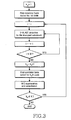
- FIG. 3 is a flowchart showing the signal processing procedure.
- Step 2) Initialization for SD-SIC (Space Domain SIC):
- step 2) and step 4 which can be called an inner loop, are processes repeated in order to detect data symbols employing identical codes, and are similar to a detection algorithm of a conventional narrowband V-BLAST system.
- the number of columns of the matrix Y k 0 - ko which is used for calculating pseudo-inverse increases up to the number of multi-paths, and a matrix exactly using all correlations between spreading codes is employed.
- the inner loop computes SINR based on MCI when processing detection ordering.
- step 1) and step 4 which are called an outer loop, are repeated whenever all data symbols corresponding to each spreading code are detected through the V-BLAST algorithm.
- the outer loop computes output signals of the correlator bank corresponding to new spreading codes.
- the outer loop reproduces MCI of data symbols of already-detected spreading codes to subtract the MCI.
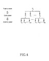
- FIG. 4 illustrates an overall structure for transmit power allocation. Such information about each transmit power is calculated at a receive end, and then is fed back to a transmit end.
- ⁇ denotes the Euclidean norm of a vector, and the squared norms are averaged over the spreading sequences as well as the data symbols and the additive noise.
- Equation 29 when MN approaches ⁇ , that is, MN ⁇ , ⁇ h approaches to ⁇ , that is, ⁇ h ⁇ .
- code power ratios found through Scheme A and Scheme B are approximately similar value to each other.
- the code power ratio relates to only average power and not instantaneous power of a channel gain. Therefore, when this value is constant and can be exactly measured at the receive end, it is enough to perform only one feedback to the transmit end from the receive end.
- transmit power allocated for each transmit antenna is founded based on the above-found transmit power allocated for each code.
- transmit power P k of all transmit antennas corresponding to one code is found by using an earlier found value.
- transmit power P k , m of each transmit antenna is allocated through the V-BLAST algorithm such that post-detection SINR, which is obtained after estimating transmit antenna symbols, is identical to all transmit antennas.
- the post-detection SINR is represented as P k 0 , m ⁇ ⁇ k 0 , m + ⁇ ⁇ k 0 , m .
- Equation 30 An algorithm for solving Equation 30 is as follows:
- Step 3 Repetition or termination for inner loop:
- Step 5 Repetition or termination for outer loop:
- nulling vector and detection ordering calculated in the power allocation procedure, can be used in the detection procedure described without repeating calculations.
- FIG. 5 is a graph showing an example simulation result according to one embodiment of the present invention.
- QPSK is employed as a modulation scheme, and an exponential decay rate ⁇ of each path power of a channel has a value of 0.5.
- variance of each path gain is normalized by using ⁇ sum having a value of one ('1').
- For spreading codes orthogonal Walsh-Hadamard codes multiplied by common scrambling codes are used.
- scrambling codes random binary codes are used.
- SNR is defined by PT / ⁇ 2 , where P is equal to P T / K.
- FIG. 5 illustrates BER performance comparison when K, M, N, L, and G are equal to '8', '4', '4', '2', and '32', respectively.
- BER performance is much more improved as compared with a case in which the successive MCI cancellation scheme is not employed.
- a simple and effective detection algorithm is suggested by employing an SIC scheme in both an antenna domain and a code domain in order to improve performance of a multi-code V-BLAST system under a frequency-selective fading channel environment. Since the SIC scheme has low hardware complexity and superior performance as compared with a PIC scheme, the present invention has an advantage in view of a system embodiment. Also, according to the present invention, a computation amount can be remarkably reduced as compared with a conventional technique using a group decorrelating detector.
- an effective transmit power allocation method is suggested based on a multi-code system characteristic in which all transmitted signals corresponding to each code reach a receive end through the same channel. That is, when a complex detection ordering process used for a typical SIC scheme is employed in a code domain, the detection ordering process seldom improves performance. Therefore, the detection ordering process is replaced with a code transmit power allocation scheme, so that the code transmit power allocation scheme achieves performance improvement.
- transmit power of codes is determined only by finding a ratio of power of a certain code signal to power of a next code signal.
- a computation amount is reduced by omitting the complex detection ordering process, and an information amount for feedback is remarkably reduced because only one ratio value is fed back to a transmit end when code transmit power information is fed back to a receive end from the transmit end.
- a constant ratio value found by measuring average power of a channel gain is employed, approximately identical performance is achieved. Accordingly, when average power of the channel gain is constant, and the average power is exactly measured, although the magnitude of an instantaneous channel gain is frequently varied depending on time, the code transmit power allocation is sufficiently achieved by performing only one feedback to the transmit end from the receive end.
Landscapes
- Engineering & Computer Science (AREA)
- Computer Networks & Wireless Communication (AREA)
- Signal Processing (AREA)
- Quality & Reliability (AREA)
- Physics & Mathematics (AREA)
- Electromagnetism (AREA)
- Power Engineering (AREA)
- Radio Transmission System (AREA)
- Mobile Radio Communication Systems (AREA)
Abstract
Description
- The present invention relates to a wireless communication apparatus and a method for a multiple transmit and receive antenna system using multiple codes, and more particularly to an apparatus and a method, which can allocate transmit power depending on transmit signals.
- Generally, a Bell Labs layered space-time (BLAST) system uses a multiple transmit-receive antenna. The BLAST system employs suitable signal processing at a receive end to improve spectral efficiency. In other words, a high data rate is achieved by transferring independent substreams from multiple transmit/receive antennas under a rich-scattering wireless channel environment employing channels independent of each other between transmit/receive antennas. Each transmitted signal from each transmit antenna is detected in a predetermined order according to channel conditions, and an already-detected transmitted signal is treated through a Successive Interference Cancellation (SIC) process in which a corresponding component is subtracted from a received signal when detecting the next transmitted signal. Herein, from among BLAST systems, a scheme to greater simplify signal processing by independently coding substreams is a Vertical BLAST (V-BLAST).
- Meanwhile, a multi-code CDMA system has been suggested as a transmission scheme for a high and variable data rate. Herein, according to a primary notion of the multi-code CDMA system, data of a certain user are divided into several streams and transferred in parallel by allocating an orthogonal code to each stream. Accordingly, the V-BLAST system employing the multi-code CDMA transmission scheme is expected to be an important telecommunication system in a next generation mobile telecommunication, which will require a high data rate.
- A reception scheme of and a performance analysis about the V-BLAST system performed until now have been deployed under a frequency-flat fading channel environment, that is, based on the assumption that a propagation delay duration_is much smaller than a symbol duration. However, signals are seriously distorted under the frequency-flat fading channel environment having a propagation delay. This phenomenon is a more serious problem under a highspeed data telecommunication environment in which the symbol duration is very short. Therefore, under the frequency-selective fading channel environment, although the multi-code V-BLAST system employs orthogonal codes, an interference occurrence between codes is inevitable. Accordingly, it is necessary to remove the interference occurrence between codes.
- A conventional method employs a group detection technique used in a CDMA system in order to remove correlation between codes. However, a maximum dimension of a matrix required while inverting a matrix for a group decorrelating detector through the group detection technique is equal to a number obtained after multiplying the number of antennas by the number of codes. Accordingly, as the number of used codes increases, a computation amount remarkably increases, and the group detection technique will encounter serious problems when applied to a real system.
- Conventional techniques also include a technique for removing Multi-Code Interference (MCI) by using a parallel interference cancellation scheme in a multi-code system of a single transmit-receive antenna. However, since the technique has to simultaneously process received signals de-spread with respect to all codes, the technique has a problem in that hardware complexity increases in proportion to the number of codes. On the other hand, since a SIC scheme individually processes each received signal for each code in order, the SIC scheme has a relatively low hardware complexity as compared with a parallel Interference Cancellation (PIC) scheme.
- Meanwhile, according to a characteristic of a multi-code system, all transmitted signals corresponding to each code reach a receive end through the same channel. Herein, after de-spreading the transmitted signals, a receive power difference can exist due to difference between correlation values of codes. However, in the multi-code system, intensity of receive power seldom exists with respect to all codes. This is a characteristic different from an uplink multi-user CDMA environment. Generally, in the SIC scheme, a signal with the greatest strength is detected first of all, so that reliability increases. Accordingly, if the SIC scheme is employed to mitigate MCI, a process for detection ordering employed through a conventional SIC scheme will have a negligible effect. Accordingly, it is necessary to overcome performance limitations for successive MCI cancellation methods caused by the SIC scheme.
- The publication titled "Optimal Power Allocation Scheme on Generalized Layered Space-Time Coding Systems," by Leung Hang Ching Jason et al., refers to an optimal power allocation scheme on generalized layered space-time coding systems. Both the design and the decoding of space-time code become complex, for example, for a 8-transmit antenna system with QPSK symbol that requires calculating the Euclidean distances. A generalized layered space time, GLST, code structure reduces the complexity by separating transmit antennas into groups. By equalizing the derivative of an individual FER, the optimum performance of the GLST system can be attained. Through simulations, it has been shown that power allocation can lead to a significant performance gain, around 1 to 2.5 dB depending on the system configuration. According to a general layout of a GLST system R space-time encoders are used which are by themselves optimum space-time encoders. The i-th encoder occupies a total of ni transmit antennas during the transmission. The number of transmit antennas used by each encoder can be different and the total number used is equal to the total number of transmit antennas. The assignment of the transmit antennas to the space-time coder is controlled by a sequence of mappings in time. In decoding the transmit side knows nothing about the channel and the receive side has perfect knowledge about it. First, an order of decoding is selected. This order can affect the system performance. Different power levels are allocated to different codes according to their positions in the decoding order. As this power allocation has to be done at the transmitter which has no knowledge of the instantaneous channel information, the transmitter can select an arbitrary decoding order and then allocate power according to that order.
- The publication titled "Variable Rate Space-Time Block Codes in MPSK Systems," by II-Min Kim and Vahin Tarokh, refers to variable rate space-time block codes in MPSK systems. A multiple antenna systems is considered when combined array processing with space time coding is used. Variable rate space-time block codes are presented for two, three and four transmit antennas and optimize the transmit power so that the average BER is minimized.
- Accordingly, the present invention has been made to solve the above-mentioned problems occurring in conventional systems. It is the object of the present invention to provide an essential technique in a next generation mobile telecommunication requiring a high data rate by suggesting an effective method for performance improvement of a multi-code V-BLAST system.
- This object is solved by the subject matter of the independent claims.
- Preferred embodiments are defined by the dependent claims.
- An aspect of the present invention is to provide an effective detection algorithm for a multi-code V-BLAST system and a transmit power allocation method for the detection algorithm under a frequency-selective fading channel environment.
- Another aspect of the present invention is to provide a Successive Interference Cancellation (SIC) in both a code domain and an antenna domain by using a suggested detection algorithm so as to successively perform cancellation with respect to Multi-Code Interference (MCI).
- A further aspect of the present invention is to provide an effective transmit power allocation method suitable for a detection algorithm.
- In order to accomplish the above, there is provided a method for allocating transmit power in a receiver of a multi-code multiple antenna system including M transmit antennas and N receive antennas, the method employing K spreading codes to distinguish channels, the method including steps of determining a power ratio

- There is further provided a method for allocating transmit power in a transmitter of a multi-code multiple antenna system including M transmit antennas and N receive antennas, the method employing K spreading codes to distinguish channels, the method including steps of receiving a power ratio (γ) between transmit power (Pk ,P k+1) to be allocated to each of two successive spreading codes, as feedback information send from a receiver and allocating the transmit power (Pk ) according to K spreading codes by substituting the power ratio (γ) and total transmit power (PT ) into an equation,

- There is still further provided a method for allocating transmit power in a multi-code multiple antenna system including M transmit antennas and N receive antennas, the method employing K spreading codes to distinguish channels, the method including steps of determining a power ratio (γ) such that, from among the K channels transmitted through the M transmit antennas has been measured, a signal-to-noise of each of which has been measured, a higher power is allocated to a channel with a higher signal-to-noise ratio than to a channel with a lower signal-to-nose-ratio; dividing total transmit power (PT ) into transmit power corresponding to each of the K channels by using the power ratio (γ); and distributing the transmit power divided according to the K channels to each of the M antennas.
- The above object and other aspects, features and advantages of the present invention will be more apparent from the following detailed description taken in conjunction with the accompanying drawings, in which:
-
FIG. 1 is a block diagram illustrating a wireless communication system according to one embodiment of the present invention; -
FIG. 2 is a detailed block diagram illustrating a successive MCI cancellation with V-BLAST detection part of a receiver structure shown inFIG. 1 ; -
FIG. 3 is a flowchart showing a signal processing procedure; -
FIG. 4 illustrates an overall structure for transmit power allocation; and -
FIG. 5 is a graph showing an example simulation result according to one embodiment of the present invention. - Hereinafter, preferred embodiments of the present invention will be described in detail with reference to the accompanying drawings. Note that the same or similar components in drawings are designated by the same reference numerals as far as possible although they are shown in different drawings. In the following description of the present invention, a detailed description of known functions and configurations incorporated herein will be omitted when it may make the subject matter of the present invention unclear.
- An effective detection algorithm for a multi-code V-BLAST system and a transmit power allocation method for the detection algorithm under a frequency-selective fading channel environment will now be described in detail. In particular, the detection algorithm suggested according to the present invention employs a method for successively canceling a Multi-Code Interference (MCI). Accordingly, a Successive Interference Cancellation (SIC) is employed in both a code domain and a space domain. An effective transmit power allocation suitable for such a detection algorithm is also described. Therefore, transmit power allocated to each code is computed using the effective transmit power allocation suitable for such a detection algorithm. Herein, the transmit power is determined as a simple ratio of power of a certain code signal to power of a next code signal. Also, transmit power is allocated to each transmit antenna based on the computed code transmit power. As described above, transmit power computed at a receive end is fed back toward a transmit end through a feedback channel.
- In addition, a detection algorithm according to the present invention proposes signal processing suitable for a V-BLAST system with respect to received signals propagation-delayed by a time period as long as a chip time unit, based on an equation thoroughly reflecting all correlation between codes. In other words, a V-BLAST detection algorithm is performed by a particular antenna based on an presumption that output signals of rake fingers obtained through various multi-paths are received by additional virtual receive antennas. In other words, this is a result obtained when the multi-path diversity obtainable in a CDMA method is regarded as the virtual receive antenna diversity. Also, when detecting a transmitted signal in a code domain, a simple SIC scheme is employed to remarkably reduce the complexity of an overall system and to prevent performance deterioration due to MCI. That is, the simple SIC scheme avoids a problem of increasing hardware complexity caused by the "Parallel Interference Cancellation (PIC)". scheme and problems of increasing a computational amount caused when the conventional group de-correlating detector is employed, by constantly maintaining matrix dimension when inverting a matrix as the number of independent transmitted data corresponding to a code, that is, the number of transmit antennas regardless of increase of the number of multi-codes. The suggested algorithm employs the SIC method in a code domain, as well as in an antenna domain.
- Also, an effective transmit power allocation method suitable for such a detection algorithm is suggested. To this end, transmit power allocated to each code is computed. This transmit power is determined as a simple ratio of power of a certain code signal to power of a next code signal. At this time, a greater amount of power is allocated to the first detected code signal in an order predetermined between transmit/receive ends without performing detection ordering of each code. This is performed to improve performance of the overall system, on the assumption that Signal-to-Interference-Noise Ratio (SINR) is inferior because the first detected code signal includes more interference signals, so that performance of an overall system is more degraded. Additionally, when subtracting a next detected transmit signal from a detected signal in order to perform such transmit power allocation, it is possible to effectively prevent performance degradation resulting from error propagation. These phenomena correspond to effects such as performance improvement when performing detection ordering in a conventional SIC scheme. Accordingly, as described above, performance can be effectively improved by employing a simpler transmit power allocation and omitting a complex detection ordering process in a code domain in which performance cannot be improved. Finally, transmit power allocated to each transmit/receive antenna is found based on calculated transmit power for each code. As described above, information about transmit power computed at a receive end is fed back toward a transmit end through a feedback channel.
-
FIG. 1 is a block diagram illustrating a wireless communication system according to one embodiment of the present invention. In the system shown inFIG. 1 , it is assumed that a multiple transmit/receive antenna system uses K spreading codes, M transmit antennas, and N receive antennas. First, a data input stream is divided into KxM parallel substreams through a serial-to-parallel converter. Each transmit antenna creates transmission signals by multiplying K substreams by mutually different spreading codes, and then by summing the resultants. - As a result, in a symbol duration, a complex base band equivalent of a transmit signal created by means of a Kth spreading code in an mth transmit antenna can be represented as the following Equation 1:

- Pk,m : transmit power for the kth code at the mth transmit antenna:
- dk,m : data symbol for the kth code at the mth transmit antenna:
- ck (t): rectangular-shaped spreading waveform for the kth code which takes on the values ±1 and is defined in 0 ≤ t ≤ T:
- T : data symbol duration. ...(1)
- M : number of total transmit antennas
- In
Equation 1, ck (t) is defined by the following Equation 2:


- Also, a summation of transmit power of all transmit antennas corresponding to kth code is called Pk , and a summation of transmit power for all codes is represented as Pt . That is, the Pk and Pt are represented as


- It is assumed that a channel model between a specific transmit antenna and a specific receive antenna is a frequency-selective Rayleigh fading channel. Based on a tapped delay line multi-path channel model, a complex channel impulse response from an mth transmit antenna to a pth receive antenna can be represented as the following Equation 3:

- At this time, a signal received in a pth receive antenna can be represented as the following Equation 4:

- Such signals received at each receive antenna are processed through the suggested successive MCI cancellation method with V-BLAST detection. As a result, transmitted data are estimated.
- Hereinafter, a successive MCI cancellation scheme for a multi-code V-BLAST system will be described. To this end, an output signal of a correlator bank for a specific code is represented as an equation without the successive MCI cancellation, which provides the basis for the below description about a detection algorithm for the successive MCI cancellation.
- It is assumed that each receive antenna has a rake receiver structure for detecting a received signal corresponding to each multi-path. At this time, in order to detect substreams corresponding to k0 th, on the assumption that each receive antenna allows a received signal to pass a correlator bank corresponding to k0 th, a complex baseband received signal corresponding to an output of the correlator bank is calculated. For the calculation, a correlator output corresponding to a k0 th code at an lth rake finger of a pth receive antenna is represented as Zk
0 ,p,l, and defined by the following Equation 5:
- Also, correlation between two predetermined codes having a discordance of a time difference of lTc from each other is defined by the following Equation 6:

- At this time, when defining and expressing all correlator outputs for k0 th codes as an NL x 1 column vector, the following Equation 7 is found:


0 ,k,p (p = 1, 2,···, N) is the L × M matrix whose element in the ith row and jth column, (Y k0 ,k,p ) ¡,j , is
- Herein, each parameter used for equation 7 is defined in
Equation 8 to Equation 12, provided below.
- Equation 9:

- Equation 10:

- Equation 11:

- Equation 12:

- A symbol (.) i.j among symbols described above represents an element of an ith column and a jth row, and a predetermined element nk,
o ,p,l of an NL x 1 Gaussian noise vector, nk0 , is defined by Equation 13:
- Accordingly, a covariance matrix of a noise vector, nk0 , can be found through the following Equation 14:

- The superscript [·] H from among subscripts used for Equation 14 denotes the conjugate transpose. An LxL matrix R̃ k
0 is a correlation matrix of a spreading waveform vector corresponding to a k0 th code and defined byEquation 15.
0 (t) = [c k0 (t),c k0 (t -Tc ),..., c k0 (t - (L -1)Tc )] T . Also, it is noted that (R̃ k0 ) i,j = R k0 ,k0 (|i - j|) is obtained from Equation 6 andEquation 15. - In Equation 7, the Y k
0 ,k0 P k0 d k0 component is a desired signal part for the data vector d k0 , and the
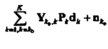

- When solving equation 16, an equation

- Expectations of the correlations are found through the following Equation 17:


- Hereinafter, a successive MCI cancellation scheme for a multi-code V-BLAST system will be described on the basis of equations described above. Herein, a linear weighting vector employs a Zero-Forcing (ZF) scheme.
FIG. 2 is a detailed block diagram illustrating a successive MCI cancellation with V-BLAST detection part of a receiver structure, andFIG. 3 is a flowchart showing the signal processing procedure. - Step 1) Initialization for CD-SIC (Code Domain SIC):
- k0 = 1

- Step 2) Initialization for SD-SIC (Space Domain SIC):
- i= 1


- Step 3) SD-SIC for the g(i)th substream of the k0th code:


- Step 4) Repetition or termination for SD-SIC:
- If i < M, increase i by one and go to Step 3.
- Otherwise, go to
Step 5. - Step 5) CD-SIC for the substreams of the (k0+1) th code:

- Step 6) Repetition or termination for CD-SIC:
- If k0 < K, increase k0 by one and go to
Step 2. - Otherwise, terminate the detection procedure. Herein, the subscripts (.)+, [.]¡ , <.> i , and <·> o(i) represent Moore-Penrose pseudo-inverse, an ith column of a given matrix, an ith row of the given matrix, and the deflated version of the given matrix, in which columns g(1), g(2), ···, g(i) have been subtracted. The subscript Q(.) denotes a quantization (slicing) operation corresponding to the modulation scheme.
- Through the algorithm, step 2) and step 4), which can be called an inner loop, are processes repeated in order to detect data symbols employing identical codes, and are similar to a detection algorithm of a conventional narrowband V-BLAST system. However, the number of columns of the matrix Y k
0 -ko , which is used for calculating pseudo-inverse increases up to the number of multi-paths, and a matrix exactly using all correlations between spreading codes is employed. Also, the inner loop computes SINR based on MCI when processing detection ordering. - In the meantime, step 1) and step 4), which are called an outer loop, are repeated whenever all data symbols corresponding to each spreading code are detected through the V-BLAST algorithm. The outer loop computes output signals of the correlator bank corresponding to new spreading codes. The outer loop reproduces MCI of data symbols of already-detected spreading codes to subtract the MCI.
- Hereinafter, based on the above-described successive MCI cancellation algorithm, a transmit power allocation scheme for the successive MCI cancellation algorithm will be described. First, all transmit power, that is, all code transmit power for all transmit signals employing identical codes is allocated. Based on the allocated transmit power, transmit power of a variety of antennas corresponding to each code, that is, transmit power of each antenna is allocated.
FIG. 4 illustrates an overall structure for transmit power allocation. Such information about each transmit power is calculated at a receive end, and then is fed back to a transmit end. When describing a transmit power allocation method, it is assumed that error propagation due to already detected signals does not exist. - Hereinafter, two methods for allocating code transmit power, i.e. Scheme A and Scheme B, are describes below:
- In Scheme A, when calculating a code SINR, a channel is given, and a mean value of code values is calculated. Also, each code transmit power is determined such that the following equations are satisfied. Herein, when allocating code transmit power, it is assumed that all symbols of each transmit antenna corresponding to a specific code have identical transmit power. That is, it is assumed that an equation Pk,m=Pk /M is achieved for all ks and ms.
- The following Equation 19 defines the SINR in a code domain for a k0 th code Equation 19:

0 ,k0 P k0 d k0 in Equation 19 is the desired signal vector and


- To find the code power set that satisfy
Equation 20, we assume that all space domain power components for each code have the same values, i.e. Pk,m = Pk /M for all k and m. Using Equation 17, it can be shown thatEquation 20 is reduced to Equations 21-24:


- Solving K + 1 simultaneous equations in Equation 21 as derived in Appendix A, we can find the code power values as


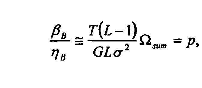
- Using Equation 23 and Equation 24, β / η in Equation 26 provides Equation 27, calculated as:

- If we assume that G»L, Equation 28 may be approximated as:

- Note that γ in Equation 26 is the power ratio between the two adjacent code powers, i.e. γ = P k+1/Pk for k = 1,2,···, K -1. From
Equation 25, it can be seen that the code power values are determined by the total given transmit power PT and the power ratio γ. - In scheme B, a mean value for both codes and channels is found when calculating a code SINR. Similarly, when β, and η corresponding to Scheme B are called βB and ηB, the βB and ηB are found by using Equation 29:

- In Equation 29, when MN approaches ∞, that is, MN→∞, ρ h approaches to ρ, that is, ρ h →ρ.
- Accordingly, when the number of transmit/receive antenna increases, code power ratios found through Scheme A and Scheme B are approximately similar value to each other. Also, in Scheme B, the code power ratio relates to only average power and not instantaneous power of a channel gain. Therefore, when this value is constant and can be exactly measured at the receive end, it is enough to perform only one feedback to the transmit end from the receive end.
- Meanwhile, transmit power allocated for each transmit antenna is founded based on the above-found transmit power allocated for each code. In other words, transmit power Pk of all transmit antennas corresponding to one code is found by using an earlier found value. Also, transmit power Pk , m of each transmit antenna is allocated through the V-BLAST algorithm such that post-detection SINR, which is obtained after estimating transmit antenna symbols, is identical to all transmit antennas. When representing a post-detection SINR for an mth transmit antenna of a k0 th code with an assumption that β̃ k
0 ,m is power for MCI, and η̃ k0 ,m is a Gaussian noise, the post-detection SINR is represented as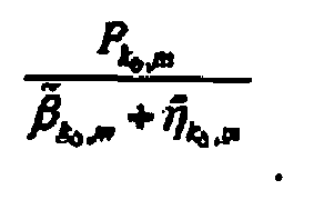
Equation 30 is satisfied:
- An algorithm for solving
Equation 30 is as follows: - Step 0) Initialization for outer loop:

- Step 1) Initialization for inner loop:


- Step 2) Calculation of β k
0 ,g(i) and η̃ k0,g(i) for the g(i)th substream of the koth code:


- Step 3) Repetition or termination for inner loop:
- Increase i by one and go to
Step 2 if i ≤ M. - Otherwise, go to
Step 4. - Step 4) Calculation of transmit antenna power for the koth code:

- Step 5) Repetition or termination for outer loop:
- Decrease ko by one and go to
Step 1 if ko ≥ 1. - Otherwise, terminate the whole antenna power allocation algorithm.
- It should be noted that all final values for the nulling vector and detection ordering, calculated in the power allocation procedure, can be used in the detection procedure described without repeating calculations.
-
FIG. 5 is a graph showing an example simulation result according to one embodiment of the present invention. Through the simulation, QPSK is employed as a modulation scheme, and an exponential decay rate δ of each path power of a channel has a value of 0.5. Also, variance of each path gain is normalized by using Ω sum having a value of one ('1'). For spreading codes, orthogonal Walsh-Hadamard codes multiplied by common scrambling codes are used. As scrambling codes, random binary codes are used. Among results of the simulation, SNR is defined by PT/ δ 2 , where P is equal to PT /K. -
FIG. 5 illustrates BER performance comparison when K, M, N, L, and G are equal to '8', '4', '4', '2', and '32', respectively. When employing the successive MCI cancellation scheme, BER performance is much more improved as compared with a case in which the successive MCI cancellation scheme is not employed. - Differently from a case of employing only the successive MCI cancellation scheme, when employing a code power allocation scheme, the BER performance is continuously improved and is not saturated as the SNR increases. Additionally, Scheme A and Scheme B, which are methods for allocating code power, have approximately identical performance. As described above, this is derived from the fact that code power ratios through Scheme A and Scheme B are approximately equal to each other when employing multiple transmit/receive antennas. When additionally allocating transmit power of an antenna, the BER performance is further improved. However, when the addition transmit power allocation is compared with a previous code transmit power allocation in view of performance improvement, their difference in view of BER performance improvement is small.
- As described above, according to the present invention, a simple and effective detection algorithm is suggested by employing an SIC scheme in both an antenna domain and a code domain in order to improve performance of a multi-code V-BLAST system under a frequency-selective fading channel environment. Since the SIC scheme has low hardware complexity and superior performance as compared with a PIC scheme, the present invention has an advantage in view of a system embodiment. Also, according to the present invention, a computation amount can be remarkably reduced as compared with a conventional technique using a group decorrelating detector.
- Additionally, according to the present invention, an effective transmit power allocation method is suggested based on a multi-code system characteristic in which all transmitted signals corresponding to each code reach a receive end through the same channel. That is, when a complex detection ordering process used for a typical SIC scheme is employed in a code domain, the detection ordering process seldom improves performance. Therefore, the detection ordering process is replaced with a code transmit power allocation scheme, so that the code transmit power allocation scheme achieves performance improvement. Herein, owing to the above-described multi-code system characteristic, transmit power of codes is determined only by finding a ratio of power of a certain code signal to power of a next code signal. Accordingly, a computation amount is reduced by omitting the complex detection ordering process, and an information amount for feedback is remarkably reduced because only one ratio value is fed back to a transmit end when code transmit power information is fed back to a receive end from the transmit end. In particular, when employing a multi-antenna system having a great number of antennas, although a constant ratio value found by measuring average power of a channel gain is employed, approximately identical performance is achieved. Accordingly, when average power of the channel gain is constant, and the average power is exactly measured, although the magnitude of an instantaneous channel gain is frequently varied depending on time, the code transmit power allocation is sufficiently achieved by performing only one feedback to the transmit end from the receive end.
- While the invention has been shown and described with reference to certain preferred embodiments thereof, it will be understood by those skilled in the art that various changes in form and details may be made therein without departing from the scope of the invention.
Claims (8)
- A method for allocating transmit power in a receiver of a multi-code multiple antenna system including M transmit antennas and N receive antennas, the method employing K spreading codes to distinguish channels, the method comprising the steps of:determining a power ratio γ between transmit power of two adjacent spreading codes by using a ratio
 transmitting a determined power ratio γ to a transmitter,wherein the ratio γ is proportional to the power of the combined channel signals, is inverse proportional to the noise power, and is determined to have a value within a range between '0' and '1'.
 - The method as claimed in claim 1, wherein the ratio γ is determined by means of an equation

wherein PT denotes total given transmit power,
- The method as claimed in claim 2, wherein when G is approximate to L,


- The method as claimed in claim 2, wherein, in finding a signal-to-noise according to the spreading codes by calculating mean values of the all channels,


wherein all |hp,m,l |2,s for a particular path index l are assumed to be independent and identically distributed random variables with finite mean Ω l for all p and m. - A method for allocating transmit power in a transmitter of a multi-code multiple antenna system including M transmit antennas and N receive antennas, the method employing K spreading codes to distinguish channels, the method comprising the steps of:receiving a power ratio γ between transmit powers Pk , P k+1 to be allocated to each of two adjacent spreading codes, as feedback information sent from a receiver; andallocating the transmit power Pk according to K spreading codes by substituting the power ratio γ and total transmit power PT into equation

- The method as claimed in claim 5, further comprising a step of allocating transmit power to each of the M transmit antennas by distributing the transmit power Pk allocated according to each spreading code to the M transmit antennas.
- The method as claimed in claim 6, wherein transmit power Pk for each of the M transmit antennas is allocated by means of equation

k = 1,2,···, K, m = 1,2,···, M,
wherein M denotes the number of total transmit antennas, k denotes an index designating a spreading code, and m denotes an index designating a transmit antenna. - The method as claimed in claim 6, wherein the step dividing transmit power P k
0 for a predetermined channel k 0 from among K channels into transmit power of each of M antennas comprises the steps of:1) setting ko to K;2) determining G k0 by means of (Y k0 ,k0 )+ after a predetermined index i is set to '1';3) calculating β̃ k0 ,g(i) and η̃ k0,g(i) for a g(i)th substream of k 0 by mean of equation;


 4) determining transmit power of a channel ko in a g(i)th antenna equation;
wherein, the i is increased by '1', G k0 corresponding to the increased i is determined by means of (〈Y k0 ,k0 〉g ( i ) )+, and then, a process for determining transmit power by means of steps 3) and 4) is repeated until the i reaches M.
Applications Claiming Priority (2)
| Application Number | Priority Date | Filing Date | Title |
|---|---|---|---|
| KR2003058555 | 2003-08-23 | ||
| KR1020030058555A KR100969767B1 (en) | 2003-08-23 | 2003-08-23 | Transmission Power Allocation Method for Multiple Transceiver Antenna Systems Using Multiple Codes |
Publications (3)
| Publication Number | Publication Date |
|---|---|
| EP1511187A2 EP1511187A2 (en) | 2005-03-02 |
| EP1511187A3 EP1511187A3 (en) | 2009-11-04 |
| EP1511187B1 true EP1511187B1 (en) | 2013-06-05 |
Family
ID=34101834
Family Applications (1)
| Application Number | Title | Priority Date | Filing Date |
|---|---|---|---|
| EP04019982.0A Expired - Lifetime EP1511187B1 (en) | 2003-08-23 | 2004-08-23 | Transmission power control for multiple codes multiple antennas system |
Country Status (3)
| Country | Link |
|---|---|
| EP (1) | EP1511187B1 (en) |
| KR (1) | KR100969767B1 (en) |
| CN (1) | CN100505581C (en) |
Families Citing this family (2)
| Publication number | Priority date | Publication date | Assignee | Title |
|---|---|---|---|---|
| KR20110036489A (en) * | 2009-10-01 | 2011-04-07 | 삼성전자주식회사 | LT-Advanced System and Uplink Power Control Method in the System |
| WO2014172377A1 (en) * | 2013-04-16 | 2014-10-23 | Kandou Labs, S.A. | Methods and systems for high bandwidth communications interface |
Family Cites Families (3)
| Publication number | Priority date | Publication date | Assignee | Title |
|---|---|---|---|---|
| JP2001094487A (en) * | 1999-09-22 | 2001-04-06 | Matsushita Electric Ind Co Ltd | Radio transmission apparatus and transmission diversity method |
| GB0110125D0 (en) | 2001-04-25 | 2001-06-20 | Koninkl Philips Electronics Nv | Radio communication system |
| EP1255369A1 (en) | 2001-05-04 | 2002-11-06 | TELEFONAKTIEBOLAGET LM ERICSSON (publ) | Link adaptation for wireless MIMO transmission schemes |
-
2003
- 2003-08-23 KR KR1020030058555A patent/KR100969767B1/en not_active Expired - Fee Related
-
2004
- 2004-08-23 EP EP04019982.0A patent/EP1511187B1/en not_active Expired - Lifetime
- 2004-08-23 CN CNB200410100594XA patent/CN100505581C/en not_active Expired - Fee Related
Also Published As
| Publication number | Publication date |
|---|---|
| EP1511187A2 (en) | 2005-03-02 |
| KR100969767B1 (en) | 2010-07-13 |
| CN1627660A (en) | 2005-06-15 |
| KR20050020533A (en) | 2005-03-04 |
| EP1511187A3 (en) | 2009-11-04 |
| CN100505581C (en) | 2009-06-24 |
Similar Documents
| Publication | Publication Date | Title |
|---|---|---|
| EP1894312B1 (en) | A method and apparatus for impairment correlation estimation in a wireless communication receiver | |
| KR100948007B1 (en) | Wireless transmission using an adaptive transmit antenna array | |
| US7212578B2 (en) | Transmit diversity apparatus and method using two or more antennas | |
| EP1575188B1 (en) | Apparatus and method for receiving signal in a multiple-input multiple-output communication system | |
| US7397843B2 (en) | Reduced complexity soft value generation for multiple-input multiple-output (MIMO) joint detection generalized RAKE (JD-GRAKE) receivers | |
| US6721293B1 (en) | Unsupervised adaptive chip separation filter for CDMA terminal | |
| US7437135B2 (en) | Joint channel equalizer interference canceller advanced receiver | |
| EP0926913A2 (en) | Cellular radio communication system with user partioning by antenna beam forming | |
| US7535970B2 (en) | Wireless communication apparatus and method for multiple transmit and receive antenna system using multiple codes | |
| EP1157477A1 (en) | Adaptive channel equalizer | |
| US20070189362A1 (en) | Method and system for channel estimation, related receiver and computer program product | |
| WO2000054418A1 (en) | Unsupervised adaptive chip separation filter for cdma terminal | |
| US7184465B2 (en) | Signal processing method and apparatus for a spread spectrum radio communication receiver | |
| Park et al. | Transmit power allocation for successive interference cancellation in multicode MIMO systems | |
| CN101213762B (en) | A method and apparatus for impairment correlation estimation in a wireless communication receiver | |
| EP1511187A2 (en) | Transmission power control for multiple codes multiple antennas system | |
| Li et al. | Nonblind and semiblind space–time-frequency multiuser detection for space–time block-coded MC-CDMA | |
| KR20070104570A (en) | Joint detection method and base station used in wireless communication system with antenna array | |
| Hassell Sweatman et al. | Multiuser detection for CDMA antenna array receivers using spatial equivalence classes | |
| Dahlhaus et al. | Smart antenna concepts for the UMTS terrestrial radio access | |
| Bosanska et al. | Performance evaluation of intra-cell interference cancelation in D-TxAA HSDPA | |
| Kocian et al. | Iterative joint data detection and channel estimation of DS/CDMA signals in multipath fading using the SAGE algorithm | |
| de Lamare et al. | Blind adaptive space-time block-coded receivers for DS-CDMA systems in multipath channels based on the constant modulus criterion | |
| Medina et al. | Channel estimation for RLS-based linearly constrained minimum variance receivers | |
| Dahlhaus et al. | Comparison of conventional and adaptive receiver concepts for the UTRA downlink |
Legal Events
| Date | Code | Title | Description |
|---|---|---|---|
| PUAI | Public reference made under article 153(3) epc to a published international application that has entered the european phase |
Free format text: ORIGINAL CODE: 0009012 |
|
| 17P | Request for examination filed |
Effective date: 20040823 |
|
| AK | Designated contracting states |
Kind code of ref document: A2 Designated state(s): AT BE BG CH CY CZ DE DK EE ES FI FR GB GR HU IE IT LI LU MC NL PL PT RO SE SI SK TR |
|
| AX | Request for extension of the european patent |
Extension state: AL HR LT LV MK |
|
| PUAL | Search report despatched |
Free format text: ORIGINAL CODE: 0009013 |
|
| AK | Designated contracting states |
Kind code of ref document: A3 Designated state(s): AT BE BG CH CY CZ DE DK EE ES FI FR GB GR HU IE IT LI LU MC NL PL PT RO SE SI SK TR |
|
| AX | Request for extension of the european patent |
Extension state: AL HR LT LV MK |
|
| 17Q | First examination report despatched |
Effective date: 20100122 |
|
| AKX | Designation fees paid |
Designated state(s): DE FI FR GB IT SE |
|
| RAP1 | Party data changed (applicant data changed or rights of an application transferred) |
Owner name: SEOUL NATIONAL UNIVERSITY INDUSTRY FOUNDATION Owner name: SAMSUNG ELECTRONICS CO., LTD. |
|
| REG | Reference to a national code |
Ref country code: DE Ref legal event code: R079 Ref document number: 602004042329 Country of ref document: DE Free format text: PREVIOUS MAIN CLASS: H04B0007005000 Ipc: H04W0052420000 |
|
| GRAP | Despatch of communication of intention to grant a patent |
Free format text: ORIGINAL CODE: EPIDOSNIGR1 |
|
| RIC1 | Information provided on ipc code assigned before grant |
Ipc: H04W 52/42 20090101AFI20121128BHEP Ipc: H04W 52/16 20090101ALI20121128BHEP |
|
| GRAS | Grant fee paid |
Free format text: ORIGINAL CODE: EPIDOSNIGR3 |
|
| GRAA | (expected) grant |
Free format text: ORIGINAL CODE: 0009210 |
|
| AK | Designated contracting states |
Kind code of ref document: B1 Designated state(s): DE FI FR GB IT SE |
|
| REG | Reference to a national code |
Ref country code: GB Ref legal event code: FG4D |
|
| REG | Reference to a national code |
Ref country code: DE Ref legal event code: R096 Ref document number: 602004042329 Country of ref document: DE Effective date: 20130801 |
|
| PG25 | Lapsed in a contracting state [announced via postgrant information from national office to epo] |
Ref country code: SE Free format text: LAPSE BECAUSE OF FAILURE TO SUBMIT A TRANSLATION OF THE DESCRIPTION OR TO PAY THE FEE WITHIN THE PRESCRIBED TIME-LIMIT Effective date: 20130605 Ref country code: FI Free format text: LAPSE BECAUSE OF FAILURE TO SUBMIT A TRANSLATION OF THE DESCRIPTION OR TO PAY THE FEE WITHIN THE PRESCRIBED TIME-LIMIT Effective date: 20130605 |
|
| PLBE | No opposition filed within time limit |
Free format text: ORIGINAL CODE: 0009261 |
|
| STAA | Information on the status of an ep patent application or granted ep patent |
Free format text: STATUS: NO OPPOSITION FILED WITHIN TIME LIMIT |
|
| 26N | No opposition filed |
Effective date: 20140306 |
|
| REG | Reference to a national code |
Ref country code: FR Ref legal event code: ST Effective date: 20140430 |
|
| REG | Reference to a national code |
Ref country code: DE Ref legal event code: R097 Ref document number: 602004042329 Country of ref document: DE Effective date: 20140306 |
|
| PG25 | Lapsed in a contracting state [announced via postgrant information from national office to epo] |
Ref country code: FR Free format text: LAPSE BECAUSE OF NON-PAYMENT OF DUE FEES Effective date: 20130902 |
|
| PGFP | Annual fee paid to national office [announced via postgrant information from national office to epo] |
Ref country code: IT Payment date: 20170810 Year of fee payment: 14 Ref country code: DE Payment date: 20170720 Year of fee payment: 14 Ref country code: GB Payment date: 20170720 Year of fee payment: 14 |
|
| REG | Reference to a national code |
Ref country code: DE Ref legal event code: R119 Ref document number: 602004042329 Country of ref document: DE |
|
| GBPC | Gb: european patent ceased through non-payment of renewal fee |
Effective date: 20180823 |
|
| PG25 | Lapsed in a contracting state [announced via postgrant information from national office to epo] |
Ref country code: IT Free format text: LAPSE BECAUSE OF NON-PAYMENT OF DUE FEES Effective date: 20180823 Ref country code: DE Free format text: LAPSE BECAUSE OF NON-PAYMENT OF DUE FEES Effective date: 20190301 |
|
| PG25 | Lapsed in a contracting state [announced via postgrant information from national office to epo] |
Ref country code: GB Free format text: LAPSE BECAUSE OF NON-PAYMENT OF DUE FEES Effective date: 20180823 |