EP1511134B1 - Pulsed laser oscillator in single longitudinal mode stabilised in frequency and relative operative method - Google Patents
Pulsed laser oscillator in single longitudinal mode stabilised in frequency and relative operative method Download PDFInfo
- Publication number
- EP1511134B1 EP1511134B1 EP04103952A EP04103952A EP1511134B1 EP 1511134 B1 EP1511134 B1 EP 1511134B1 EP 04103952 A EP04103952 A EP 04103952A EP 04103952 A EP04103952 A EP 04103952A EP 1511134 B1 EP1511134 B1 EP 1511134B1
- Authority
- EP
- European Patent Office
- Prior art keywords
- resonant cavity
- mirror
- piezoceramic
- beating
- frequency
- Prior art date
- Legal status (The legal status is an assumption and is not a legal conclusion. Google has not performed a legal analysis and makes no representation as to the accuracy of the status listed.)
- Not-in-force
Links
Images
Classifications
-
- H—ELECTRICITY
- H01—ELECTRIC ELEMENTS
- H01S—DEVICES USING THE PROCESS OF LIGHT AMPLIFICATION BY STIMULATED EMISSION OF RADIATION [LASER] TO AMPLIFY OR GENERATE LIGHT; DEVICES USING STIMULATED EMISSION OF ELECTROMAGNETIC RADIATION IN WAVE RANGES OTHER THAN OPTICAL
- H01S3/00—Lasers, i.e. devices using stimulated emission of electromagnetic radiation in the infrared, visible or ultraviolet wave range
- H01S3/10—Controlling the intensity, frequency, phase, polarisation or direction of the emitted radiation, e.g. switching, gating, modulating or demodulating
- H01S3/10084—Frequency control by seeding
- H01S3/10092—Coherent seed, e.g. injection locking
-
- H—ELECTRICITY
- H01—ELECTRIC ELEMENTS
- H01S—DEVICES USING THE PROCESS OF LIGHT AMPLIFICATION BY STIMULATED EMISSION OF RADIATION [LASER] TO AMPLIFY OR GENERATE LIGHT; DEVICES USING STIMULATED EMISSION OF ELECTROMAGNETIC RADIATION IN WAVE RANGES OTHER THAN OPTICAL
- H01S3/00—Lasers, i.e. devices using stimulated emission of electromagnetic radiation in the infrared, visible or ultraviolet wave range
- H01S3/05—Construction or shape of optical resonators; Accommodation of active medium therein; Shape of active medium
- H01S3/08—Construction or shape of optical resonators or components thereof
- H01S3/08018—Mode suppression
- H01S3/08022—Longitudinal modes
- H01S3/08031—Single-mode emission
Definitions
- the present invention refers to a pulsed laser oscillator operating in single transversal mode (STM) and an innovative operative method for making this oscillator function in single longitudinal mode (SLM) with particularly stable transmitting frequency over time ( ⁇ 1 MHz rms).
- STM single transversal mode
- SLM single longitudinal mode
- Solid state laser Laser oscillators are currently known that use a solid-state rod as active material (solid state laser).
- the geometry of the resonator is of great importance as it is responsible for the output characteristics of the beam and of the efficiency of the laser oscillator.
- the geometrical and spectral characteristics of the laser beam reach the theoretical limits of the Gaussian beams if the laser oscillator oscillates in SLM and in STM.
- a resonant cavity comprises an active material that is located between two mirrors that form the cavity.
- the oscillation in few transversal and longitudinal modes is forced by placing a diaphragm opening in the resonator that acts as a spatial filter; this filter rejects the higher order modes (that have a wide diameter) and lets the lower order modes pass, that is those that have a small transversal section in relation to the active material.
- the active material consists of a solid-state rod, for example with circular section, with associated pumping system.
- the oscillation on a single longitudinal mode can be obtained through the use of a suitable band-pass optic filter.
- Another technique to obtain the oscillation of a cavity in single longitudinal mode consists of injecting inside the cavity itself a continuous laser beam coming from a low power source.
- This continuous laser source is called injection laser; it provides the frequency reference to the entire laser system and the stability in frequency of the entire system is measured in relation to it.
- the pulsed cavity is tuned to the frequency of the injection laser by moving one of the mirrors of the cavity, for example by means of a piezoceramic translator (commonly called piezoceramic).
- the length of the cavity can be made the same as a whole multiple of the wavelength of the injection laser and the emission of laser pulses in single longitudinal mode can be obtained.
- a control apparatus In a pulsed laser oscillator of the type described a control apparatus has to be provided to make the frequency of the pulsed laser stable.
- a control apparatus of this type is present in the US patent 4918704 and makes provision of the use of an output coupling mirror having a profile of partial reflectivity that is similar to the Gaussian mathematic function.
- US 4410992 discloses a pulsed laser oscillator according to the preamble of claim 1.
- the object of the present invention is to produce a pulsed laser oscillator in single longitudinal mode stabilised in frequency that operates according to a method different from those known up to now.
- Another object is to produce an innovative operative method for a pulsed laser oscillator in single longitudinal mode.
- this object is achieved by means of a method as defined in claim 1.
- a pulsed laser oscillator is shown according to an embodiment of the invention, that comprises a resonant cavity 1.
- the resonant cavity comprises a first fixed mirror 3, a second mobile mirror 4 by means of a piezoceramic translator or "piezoceramic" 5, an active material 6 located on an optical axis between the two mirrors and constituted for example by a rod of Nd:YAG, and an optical shutter 7, for example a Pockels cell, located along said optical axis between the active material 6 and the second mirror 4.
- the active material 6 is associated to a diode pumping apparatus 8, fed by a suitable feeder 10, which is suited to energize the active material 6 to excite it to emit a radiation laser; the optical shutter 7 is instead driven by a driving device 11.
- CW continuous wave laser
- a Faraday isolator 21 is used to separate the continuous laser beam in input into the cavity 1 from the pulsed laser beam pulsed in output from the same cavity 1.
- the two mirrors 3 and 4, the active material 6 and the optical shutter 7 are aligned with each other and the distance between the two mirrors 3 and 4 constitutes the length of the cavity 1.
- the input mirror of the injection and the output mirror of the pulsed laser radiation coincide and the injection and pulsed output bands are separated angularly.
- the two circulation directions of the injection beam and the pulsed beam coincide (both clockwise, or both anti-clockwise).
- the driving device 11 keeps the optical shutter 7 closed during the pumping phase of the active material 6, typically for about 150-200 ⁇ s, and reopens it immediately after to produce the growth of the pulsed radiation, thus producing the so-called Q-switch.
- the injection of the continuous laser beam coming from the source 20 inside the cavity 1 also continues after the pumping phase; said radiation is detected by a photodiode 30 located outside the cavity 1 along the optical axis of the same and near the mirror 3; the signal coming from the photodiode 30 is then measured by an electronic control device 50, which through an amplifier 51 suitably commands the piezoceramic 5 so as to vary the length of the resonant cavity 1.
- the photodiode 30, the electronic control device 50, the amplifier 51 and the piezoceramic 5 constitute control means 2 of the length of the resonant cavity.
- the resonant cavity 1 is used as a Fabry Perot interferometer (FP) and the transmission of the laser beam injected into the cavity itself 1 in the period of time T between two successive laser pulses is continually monitored.
- the control action on the cavity 1 is obtained by modulating the length of the cavity itself thanks to the command signal sent by the electronic device 50 to the piezoceramic 5 coupled to the mirror 4 and observing the reply of the photodiode 30 to the signal sent; more precisely the length of the cavity 1 is modulated to enable the identification, with the required precision, of the position of the transmission peak of the interferometer detected with the photodiode 30.
- control action comprises a search phase for the transmission peak of the continuous radiation in the cavity 1 carried out by means of the search for the peak of the signal detected by the photodiode 30, and for determining its position.
- the electronic control device 50 comprises search means 61 ( Figure 2 ) and memorisation means 62.
- search means 61 Figure 2
- memorisation means 62 On the basis of the result of the search the electronic device 50 makes provision for the positioning of the mirror 4 by means of sending a suitable signal to the amplifier 51, and then to the piezoceramic 5, by means of command means 63.
- the waveforms of the signal sent to the piezoceramic 5 in the search phase can be of various types. Both a sinusoidal modulation and a single or double slope sawtooth modulation can be used.
- the waveforms used for scanning are generated already suitably filtered so as to have a reduced band, compatible with the response times of the piezoceramic 5, so as to avoid shocks to it and the consequent triggering of mechanical resonances which, even if dampened, reduce the performances of the system.
- so as to compensate the hysteresis effect of the piezoceramic 5, to define the optimal position it is advisable to use the measurements obtained by moving the piezoceramic 5 in the same direction as the movement used for the positioning phase. In reality the measurements obtained in the opposite directions, if suitably filtered of the hysteresis, can also provide useful indications on the optimal position of the piezoceramic 5.
- a processing phase again by means of the electronic device 50, of the measurements to identify the position of the piezoceramic that corresponds to the maximum of energy transmission of the cavity 1 on the photodiode 30.
- the positioning phase in which the command means 63 provides the piezoceramic 5 with the command for the corresponding movement of the mirror 4; in this manner the length of the cavity 1 is regulated in accordance with the position of the transmission peak detected by the photodiode 30. Said positioning of the mirror 4 comes about before the production of the next pulse (positioning phase).
- the control of the length of the cavity cannot come about with continuity since during the emission of the laser pulse it is not possible to carry out the length measurement of the cavity.
- the photodiode 30 in fact remains "blinded" during the laser pulse because of the high luminous intensity of the pulse itself. Even after the end of the laser pulse, for a given interval of time the photodiode 30 cannot operate to permit the output from the saturation of the preamplifier associated to it. For this reason it is necessary to disable the control means 2 just before the pumping action of the active material 6 and re-enable it after the end of the pulse. During this phase the mobile mirror is brought to the optimal position determined during the scanning phase and left in that position up to the produced pulse.
- the control means 2 are open, in this manner everything that comes about during the laser pulse does not alter the length of the resonator preset by the control system. In fact, before the laser pulse several disturbance sources are present caused by the command signals of the optical shutter 7 and by the leading edges of the current pulses that feed the pumping diodes 8, disturbances that could influence the correct functioning of the control apparatus 2. At the end of the pulse the control is re-activated. Because of the vibrations and the acoustic noises that can modify the length of the optical path it is best that the time that lapses between the search phase and the positioning phase is as short as possible. This is to prevent the length of the cavity from varying between the measuring instant and the positioning instant. The delay is determined both by the processing times and the times needed by the piezoceramic 5 to move to the commanded position.
- the scanning amplitude of the interferometer in the search phase can be modified while it is functioning so as to improve the sensitivity with which the control is carried out.
- the amplitude of the search scan that has to be equal to at least one Free Spectral Range (FSR) is suitable reduced around the position of the transmission peak.
- FSR Free Spectral Range
- the reduction can come about progressively or instantaneously in order to reach a minimum value called amplitude of the seal scan. If because of some very intense disturbance the transmission peak should go out of the seal scan field, the control program, that detects the absence of the peak, intervenes resetting the amplitude of the search scan to the maximum value and taking as useful peak (should there be more than one) the one nearest to the centre of the scan.
- a seal limit equal to ⁇ 1FSR can be defined so that, if the peak is released because it has reached the edges of the seal limit, the new search scan will find the new transmission peak near the centre of the scan operated by the piezoceramic.
- the "tracking" of the seal scan to the position of the transmission peak can be made when the fluctuations of the position of the transmission peak are small in comparison to the movement produced by the seal scan.
- the seal scan is moved by overlapping an offset that pursues in time the position of the transmission peak.
- the scan of the piezoceramic is symmetrical in relation to the position of the peak of the interferometer.
- the value of the optimal offset is assessed on the basis of the measurements of the position of the peaks previously detected and executing suitable means and interpolations.
- the weight with which each measurement enters in the assessment of the offset is fixed in accordance with the amplitude of the variations of position of the transmission peak. The same procedure can also be followed in the junction phase between search scan and seal scan.
- the method of controlling the laser cavity 1 is carried out in the period of time T that lapses between two successive pulses.
- This time T can be divided into N periods of time T1 that are not necessarily equal to each other.
- the first N-1 periods of time T1 are used to carry out the scan of the cavity even several times so as to measure any fluctuations of the length of the cavity (search phase).
- the last period of time T1 is used to position the mirror of cavity 4 before generating the laser pulse (positioning phase).
- the calculation of the optimal position of the cavity can be carried out in various manners.
- the simplest method is that to consider as optimal position of the piezoceramic that in correspondence with the last transmission peak measured.
- Another method consists in extrapolating the optimal position using a suitably weighed average of the last positions of the transmission peak measured during the N-1 scans of the search phase.
- the control of the length of the resonant cavity operated by the apparatus according to the invention is a control of the predictive type, that is it enables the prior identification which will be the optimal position of the mirror of cavity 4 that will generate a pulse in single longitudinal mode.
- the optical path of the radiation laser inside the cavity 1 can still change by effect of the thermal transients that occur during the positioning phase. Said changes of temperature are due, for example, to the heating caused by the pumping of the active means 6 by the diodes 8. These fluctuations of the length of the cavity are systematic and can be compensated by adding a suitable offset to the command of the piezoceramic. Through the degrading of the performances of the diodes with time (diminution of emission at equal energy in input) the value of the offset to be added to the command of the piezoceramic can vary unpredictably, therefore the laser system needs an additional control device 100 that permits the elimination of the changes within the cavity 1 caused by said variations of the characteristics of the components that occur over time.
- Said control device uses a photodiode or an optical sensor 101 and operates in this manner: it processes the optical signal coming from the pulsed laser by means of a processing device 102, it verifies the effective operation in single longitudinal mode again by means of the device 102, it assesses the movement of the transmitting frequency of the pulsed laser in relation to the value of frequency required again with the device 102, and, if necessary, it corrects the position of the mirror 4 by means of a suitable command to the piezoceramic 5 to again obtain the functioning in single longitudinal mode and to recover said movement in frequency.
- the control device 100 can operate in accordance with various methods according to variants to the embodiment of the invention.
- a first method according to the embodiment of the invention is based on the measurement of the beating signal generated by the presence of several laser modes.
- the pulsed laser radiation (Out) is periodically detected and measured by the device 102 to verify the presence of a beating between two adjacent modes of the cavity 1.
- This procedure is carried out by increasing, between one laser pulse and the next one, by a quantity D (much less than the movement equivalent to 1 FSR) the length of the cavity.
- D passes from 0 to the movement equivalent to at least 2 FSR it is possible to understand when the functioning of the laser passed from single mode to multimode.
- the optimal value of the movement D will be given by that which annuls the amplitude of the beating between the two adjacent modes; as a rather wide interval of movements that annul the beating exists in general, the optimal value can be obtained like the central one between two beating peaks.
- the photodiode 101 detects the presence of the possible beating between the adjacent modes of the pulsed laser radiation (Out); the signal F coming from the photodiode 101 is sent to the device 102 that comprises, as can be seen in Figure 3 , an amplifier 103 and a filter 104 to amplify and filter with a band centred around the value of FSR, the frequency value at which the beating of the adjacent modes occurs, said signal F, a rectifier 105 followed by an integrator 106 measures the amplitude of the beating and a device 107 provides the commands P needed by the piezoceramic 5 between one pulse and the next one, to produce the movements D needed to cover 2 FSR.
- the device 102 comprises, as can be seen in Figure 3 , an amplifier 103 and a filter 104 to amplify and filter with a band centred around the value of FSR, the frequency value at which the beating of the adjacent modes occurs, said signal F, a rectifier 105 followed by an integrator 106 measures the amplitude of the beating and
- the purpose of the use of the filter 104, of the rectifier 105 and of the integrator 106 is to detect the carrier generated by the beating at the frequency of the FSR; any other type of demodulation can be used to carry out this operation.
- the optimal value of the movement D (which will have to be used by the control system) is that which annuls the amplitude of the beating; a device 108 identifies the optimal movement D and commands the piezoceramic 5 with said optimal movement adding this value to the control algorithm in the form of offset.
- a second method in accordance with a variant of the embodiment of the invention is based on the direct measurement of the optical frequency with a heterodyne technique.
- a part of the signal coming from the pulsed laser radiation (Out) of the cavity 1 is made to beat with a signal obtained by modulating in frequency (for example with an acoustic-optical modulator 200) a portion of the injection beam coming from the continuous laser source 20, as can be seen in Figure 4 .
- the signal obtained in this manner is detected by the photodiode 101 whose signal F in output is sent to the device 102 comprising an amplifier 201 and a filter 202 for amplifying and filtering the signal F.
- a further device 203 measures the beating frequency of the signal F on each single pulse.
- the value of the frequency enables an absolute measurement of the difference in frequency between laser pulse and injector to be obtained.
- a device 204 is suited to command the piezoceramic 5 to regulate the movement of the length of the cavity 1 until the error is annulled.
- a third method in accordance with a variant of the embodiment of the invention consists in sending a part of the pulsed laser radiation (Out), made suitably divergent, through an Etalon 301 ( Figure 5 ) and measuring the interference fringes with a suitable linear system 302 of photo-sensitive sensors 101. From the analysis of the interference fringes made by the device 102 comprising an analyser 303 it is possible to establish if the laser pulse is in single mode or in multimode and the difference in frequency between pulsed laser and injection laser. Applying the scan as for finding the optimal value of the movement D in the first method, it can be established what the position is in which the pulse emitted is in single mode.
- the three methods illustrated can also be used concurrently to improve the result of compensation of the offset.
Abstract
Description
- The present invention refers to a pulsed laser oscillator operating in single transversal mode (STM) and an innovative operative method for making this oscillator function in single longitudinal mode (SLM) with particularly stable transmitting frequency over time (±1 MHz rms).
- Laser oscillators are currently known that use a solid-state rod as active material (solid state laser).
- In these laser oscillators the geometry of the resonator is of great importance as it is responsible for the output characteristics of the beam and of the efficiency of the laser oscillator. The geometrical and spectral characteristics of the laser beam reach the theoretical limits of the Gaussian beams if the laser oscillator oscillates in SLM and in STM.
- Generally a resonant cavity comprises an active material that is located between two mirrors that form the cavity. The oscillation in few transversal and longitudinal modes is forced by placing a diaphragm opening in the resonator that acts as a spatial filter; this filter rejects the higher order modes (that have a wide diameter) and lets the lower order modes pass, that is those that have a small transversal section in relation to the active material. The active material consists of a solid-state rod, for example with circular section, with associated pumping system.
- The oscillation on a single longitudinal mode can be obtained through the use of a suitable band-pass optic filter.
- Another technique to obtain the oscillation of a cavity in single longitudinal mode consists of injecting inside the cavity itself a continuous laser beam coming from a low power source. This continuous laser source is called injection laser; it provides the frequency reference to the entire laser system and the stability in frequency of the entire system is measured in relation to it. The pulsed cavity is tuned to the frequency of the injection laser by moving one of the mirrors of the cavity, for example by means of a piezoceramic translator (commonly called piezoceramic).
- In this manner the length of the cavity can be made the same as a whole multiple of the wavelength of the injection laser and the emission of laser pulses in single longitudinal mode can be obtained.
- The uses of a laser oscillator of that type are considerable, in particular for remote measurements spatially linked both to the variation of the frequency emitted (as that which comes about for the measurement of the speed of wind) and to the variation of the laser intensity transmitted (measurement of concentration of molecular species present in atmosphere that operate a selective absorption of the laser radiation on the basis of its frequency).
- In a pulsed laser oscillator of the type described a control apparatus has to be provided to make the frequency of the pulsed laser stable. A control apparatus of this type is present in the
US patent 4918704 and makes provision of the use of an output coupling mirror having a profile of partial reflectivity that is similar to the Gaussian mathematic function. -
US 4410992 discloses a pulsed laser oscillator according to the preamble of claim 1. - In view of the state of the technique described, the object of the present invention is to produce a pulsed laser oscillator in single longitudinal mode stabilised in frequency that operates according to a method different from those known up to now.
- Another object is to produce an innovative operative method for a pulsed laser oscillator in single longitudinal mode.
- In accordance with the present invention, this object is achieved by means of a method as defined in claim 1.
- The characteristics and advantages of the present invention will become evident from the following detailed description of an embodiment thereof, illustrated as non-limiting example in the enclosed drawings, in which:
-
Figure 1 is a schematic representation of a pulsed laser oscillator according to an embodiment of the invention; -
Figure 2 is a schematic representation of an electronic control device that is part of the laser oscillator inFigure 1 ; -
Figure 3 is a schematic representation of an embodiment of an additional device included in the laser oscillator inFigure 1 ; -
Figure 4 is a schematic representation of a variant of the device inFigure 3 ; -
Figure 5 is a schematic representation of another variant of the device inFigure 3 . - With reference to
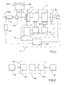
Figure 1 a pulsed laser oscillator is shown according to an embodiment of the invention, that comprises a resonant cavity 1. The resonant cavity comprises a first fixed mirror 3, a second mobile mirror 4 by means of a piezoceramic translator or "piezoceramic" 5, anactive material 6 located on an optical axis between the two mirrors and constituted for example by a rod of Nd:YAG, and an optical shutter 7, for example a Pockels cell, located along said optical axis between theactive material 6 and the second mirror 4. Theactive material 6 is associated to a diode pumping apparatus 8, fed by asuitable feeder 10, which is suited to energize theactive material 6 to excite it to emit a radiation laser; the optical shutter 7 is instead driven by a driving device 11. - A low power
continuous laser source 20, also called injection laser or continuous wave laser (CW), outside the cavity 1, injects a continuous laser beam in single frequency by means of the mirror 4 inside the cavity 1. As the mirror 4 for the input of the continuous laser is also used for the output of the pulsed laser beam (Out) from the cavity 1, a Faradayisolator 21 is used to separate the continuous laser beam in input into the cavity 1 from the pulsed laser beam pulsed in output from the same cavity 1. The two mirrors 3 and 4, theactive material 6 and the optical shutter 7 are aligned with each other and the distance between the two mirrors 3 and 4 constitutes the length of the cavity 1. In the case of the cavity being ring-shaped, the input mirror of the injection and the output mirror of the pulsed laser radiation coincide and the injection and pulsed output bands are separated angularly. The two circulation directions of the injection beam and the pulsed beam coincide (both clockwise, or both anti-clockwise). - The driving device 11 keeps the optical shutter 7 closed during the pumping phase of the
active material 6, typically for about 150-200µs, and reopens it immediately after to produce the growth of the pulsed radiation, thus producing the so-called Q-switch. - The injection of the continuous laser beam coming from the
source 20 inside the cavity 1 also continues after the pumping phase; said radiation is detected by aphotodiode 30 located outside the cavity 1 along the optical axis of the same and near the mirror 3; the signal coming from thephotodiode 30 is then measured by anelectronic control device 50, which through anamplifier 51 suitably commands the piezoceramic 5 so as to vary the length of the resonant cavity 1. Thephotodiode 30, theelectronic control device 50, theamplifier 51 and the piezoceramic 5 constitute control means 2 of the length of the resonant cavity. - The resonant cavity 1 is used as a Fabry Perot interferometer (FP) and the transmission of the laser beam injected into the cavity itself 1 in the period of time T between two successive laser pulses is continually monitored. The control action on the cavity 1 is obtained by modulating the length of the cavity itself thanks to the command signal sent by the
electronic device 50 to the piezoceramic 5 coupled to the mirror 4 and observing the reply of thephotodiode 30 to the signal sent; more precisely the length of the cavity 1 is modulated to enable the identification, with the required precision, of the position of the transmission peak of the interferometer detected with thephotodiode 30. - Therefore the control action comprises a search phase for the transmission peak of the continuous radiation in the cavity 1 carried out by means of the search for the peak of the signal detected by the
photodiode 30, and for determining its position. For this aim theelectronic control device 50 comprises search means 61 (Figure 2 ) and memorisation means 62. On the basis of the result of the search theelectronic device 50 makes provision for the positioning of the mirror 4 by means of sending a suitable signal to theamplifier 51, and then to the piezoceramic 5, by means of command means 63. - The waveforms of the signal sent to the piezoceramic 5 in the search phase can be of various types. Both a sinusoidal modulation and a single or double slope sawtooth modulation can be used. The waveforms used for scanning are generated already suitably filtered so as to have a reduced band, compatible with the response times of the piezoceramic 5, so as to avoid shocks to it and the consequent triggering of mechanical resonances which, even if dampened, reduce the performances of the system. In addition, so as to compensate the hysteresis effect of the piezoceramic 5, to define the optimal position, it is advisable to use the measurements obtained by moving the piezoceramic 5 in the same direction as the movement used for the positioning phase. In reality the measurements obtained in the opposite directions, if suitably filtered of the hysteresis, can also provide useful indications on the optimal position of the piezoceramic 5.
- At the end of the search phase there is a processing phase, again by means of the
electronic device 50, of the measurements to identify the position of the piezoceramic that corresponds to the maximum of energy transmission of the cavity 1 on thephotodiode 30. At this point there is the positioning phase, in which the command means 63 provides the piezoceramic 5 with the command for the corresponding movement of the mirror 4; in this manner the length of the cavity 1 is regulated in accordance with the position of the transmission peak detected by thephotodiode 30. Said positioning of the mirror 4 comes about before the production of the next pulse (positioning phase). - The control of the length of the cavity cannot come about with continuity since during the emission of the laser pulse it is not possible to carry out the length measurement of the cavity. The
photodiode 30 in fact remains "blinded" during the laser pulse because of the high luminous intensity of the pulse itself. Even after the end of the laser pulse, for a given interval of time thephotodiode 30 cannot operate to permit the output from the saturation of the preamplifier associated to it. For this reason it is necessary to disable the control means 2 just before the pumping action of theactive material 6 and re-enable it after the end of the pulse. During this phase the mobile mirror is brought to the optimal position determined during the scanning phase and left in that position up to the produced pulse. During the production of the laser pulse the control means 2 are open, in this manner everything that comes about during the laser pulse does not alter the length of the resonator preset by the control system. In fact, before the laser pulse several disturbance sources are present caused by the command signals of the optical shutter 7 and by the leading edges of the current pulses that feed the pumping diodes 8, disturbances that could influence the correct functioning of thecontrol apparatus 2. At the end of the pulse the control is re-activated. Because of the vibrations and the acoustic noises that can modify the length of the optical path it is best that the time that lapses between the search phase and the positioning phase is as short as possible. This is to prevent the length of the cavity from varying between the measuring instant and the positioning instant. The delay is determined both by the processing times and the times needed by the piezoceramic 5 to move to the commanded position. - The scanning amplitude of the interferometer in the search phase can be modified while it is functioning so as to improve the sensitivity with which the control is carried out. In this manner, once the position of the transmission peak has been detected, the amplitude of the search scan, that has to be equal to at least one Free Spectral Range (FSR), is suitable reduced around the position of the transmission peak. The reduction can come about progressively or instantaneously in order to reach a minimum value called amplitude of the seal scan. If because of some very intense disturbance the transmission peak should go out of the seal scan field, the control program, that detects the absence of the peak, intervenes resetting the amplitude of the search scan to the maximum value and taking as useful peak (should there be more than one) the one nearest to the centre of the scan. The same action is taken should the position of the transmission peak be found at the ends of the stroke of the piezoceramic 5; the new search scan is carried out starting from the central position of the stroke of the piezoceramic 5. In this manner it is possible to use a very limited field of movements of the piezoceramic that permits an actuator with reduced stroke to be used. A seal limit equal to ±1FSR can be defined so that, if the peak is released because it has reached the edges of the seal limit, the new search scan will find the new transmission peak near the centre of the scan operated by the piezoceramic. The "tracking" of the seal scan to the position of the transmission peak can be made when the fluctuations of the position of the transmission peak are small in comparison to the movement produced by the seal scan. If this should not come about the seal scan would start to fluctuate to keep itself centred at the transmission peak generating instabilities and oscillations of the control system. To avoid these instabilities the seal scan is moved by overlapping an offset that pursues in time the position of the transmission peak. In this manner the scan of the piezoceramic is symmetrical in relation to the position of the peak of the interferometer. The value of the optimal offset is assessed on the basis of the measurements of the position of the peaks previously detected and executing suitable means and interpolations. The weight with which each measurement enters in the assessment of the offset is fixed in accordance with the amplitude of the variations of position of the transmission peak. The same procedure can also be followed in the junction phase between search scan and seal scan.
- The method of controlling the laser cavity 1 is carried out in the period of time T that lapses between two successive pulses. This time T can be divided into N periods of time T1 that are not necessarily equal to each other. The first N-1 periods of time T1 are used to carry out the scan of the cavity even several times so as to measure any fluctuations of the length of the cavity (search phase). The last period of time T1 is used to position the mirror of cavity 4 before generating the laser pulse (positioning phase).
- The calculation of the optimal position of the cavity can be carried out in various manners. The simplest method is that to consider as optimal position of the piezoceramic that in correspondence with the last transmission peak measured. Another method consists in extrapolating the optimal position using a suitably weighed average of the last positions of the transmission peak measured during the N-1 scans of the search phase.
- The control of the length of the resonant cavity operated by the apparatus according to the invention is a control of the predictive type, that is it enables the prior identification which will be the optimal position of the mirror of cavity 4 that will generate a pulse in single longitudinal mode.
- Nevertheless the optical path of the radiation laser inside the cavity 1 can still change by effect of the thermal transients that occur during the positioning phase. Said changes of temperature are due, for example, to the heating caused by the pumping of the
active means 6 by the diodes 8. These fluctuations of the length of the cavity are systematic and can be compensated by adding a suitable offset to the command of the piezoceramic. Through the degrading of the performances of the diodes with time (diminution of emission at equal energy in input) the value of the offset to be added to the command of the piezoceramic can vary unpredictably, therefore the laser system needs anadditional control device 100 that permits the elimination of the changes within the cavity 1 caused by said variations of the characteristics of the components that occur over time. Said control device uses a photodiode or anoptical sensor 101 and operates in this manner: it processes the optical signal coming from the pulsed laser by means of aprocessing device 102, it verifies the effective operation in single longitudinal mode again by means of thedevice 102, it assesses the movement of the transmitting frequency of the pulsed laser in relation to the value of frequency required again with thedevice 102, and, if necessary, it corrects the position of the mirror 4 by means of a suitable command to the piezoceramic 5 to again obtain the functioning in single longitudinal mode and to recover said movement in frequency. - The
control device 100 can operate in accordance with various methods according to variants to the embodiment of the invention. - A first method according to the embodiment of the invention is based on the measurement of the beating signal generated by the presence of several laser modes. By means of the
photodiode 101 the pulsed laser radiation (Out) is periodically detected and measured by thedevice 102 to verify the presence of a beating between two adjacent modes of the cavity 1. This procedure is carried out by increasing, between one laser pulse and the next one, by a quantity D (much less than the movement equivalent to 1 FSR) the length of the cavity. In this manner while D passes from 0 to the movement equivalent to at least 2 FSR it is possible to understand when the functioning of the laser passed from single mode to multimode. The optimal value of the movement D will be given by that which annuls the amplitude of the beating between the two adjacent modes; as a rather wide interval of movements that annul the beating exists in general, the optimal value can be obtained like the central one between two beating peaks. - More precisely the
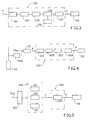
photodiode 101 detects the presence of the possible beating between the adjacent modes of the pulsed laser radiation (Out); the signal F coming from thephotodiode 101 is sent to thedevice 102 that comprises, as can be seen inFigure 3 , anamplifier 103 and afilter 104 to amplify and filter with a band centred around the value of FSR, the frequency value at which the beating of the adjacent modes occurs, said signal F, arectifier 105 followed by anintegrator 106 measures the amplitude of the beating and adevice 107 provides the commands P needed by the piezoceramic 5 between one pulse and the next one, to produce the movements D needed to cover 2 FSR. The purpose of the use of thefilter 104, of therectifier 105 and of theintegrator 106 is to detect the carrier generated by the beating at the frequency of the FSR; any other type of demodulation can be used to carry out this operation. At the end of the scan the optimal value of the movement D (which will have to be used by the control system) is that which annuls the amplitude of the beating; adevice 108 identifies the optimal movement D and commands the piezoceramic 5 with said optimal movement adding this value to the control algorithm in the form of offset. - A second method in accordance with a variant of the embodiment of the invention is based on the direct measurement of the optical frequency with a heterodyne technique. A part of the signal coming from the pulsed laser radiation (Out) of the cavity 1 is made to beat with a signal obtained by modulating in frequency (for example with an acoustic-optical modulator 200) a portion of the injection beam coming from the
continuous laser source 20, as can be seen inFigure 4 . The signal obtained in this manner is detected by thephotodiode 101 whose signal F in output is sent to thedevice 102 comprising anamplifier 201 and afilter 202 for amplifying and filtering the signal F. Afurther device 203 measures the beating frequency of the signal F on each single pulse. - The value of the frequency enables an absolute measurement of the difference in frequency between laser pulse and injector to be obtained. On the basis of this information a
device 204 is suited to command the piezoceramic 5 to regulate the movement of the length of the cavity 1 until the error is annulled. - A third method in accordance with a variant of the embodiment of the invention consists in sending a part of the pulsed laser radiation (Out), made suitably divergent, through an Etalon 301 (
Figure 5 ) and measuring the interference fringes with a suitablelinear system 302 of photo-sensitive sensors 101. From the analysis of the interference fringes made by thedevice 102 comprising ananalyser 303 it is possible to establish if the laser pulse is in single mode or in multimode and the difference in frequency between pulsed laser and injection laser. Applying the scan as for finding the optimal value of the movement D in the first method, it can be established what the position is in which the pulse emitted is in single mode. - The three methods illustrated can also be used concurrently to improve the result of compensation of the offset.
Claims (5)
- Operative method of a pulsed laser oscillator in single longitudinal mode stabilised in frequency, the laser oscillator comprising a resonant cavity (1) including an active material (6) located on an optical axis between at least two mirrors (3, 4),
said method comprising:the illumination of said active material (6) with a continuous laser beam coming from means (20) outside the resonant cavity (1) to make the laser oscillator operate in single longitudinal mode,the energizing of said active material (6) to excite it to emit a pulsed laser radiation formed by a succession of output laser pulses (Out) directed towards one (4) of said mirrors (3, 4) and coming out of the resonant cavity (1) through said one mirror (4),said method comprising the steps of:modulating the length of the resonant cavity (1) in a search phase of the transmission peak of said continuous laser beam by said resonant cavity (1) in a period of time (T) between the generation of a pulse of said succession of pulses and that of the next pulse,said search phase comprising the detection of said continuous laser beam transmitted by the resonant cavity (1) through another one (3) of said cavity mirrors (3, 4), the measurement of a signal corresponding to the continuous laser beam detected, the memorization of said measurement and the transmission of a command signal to a piezoceramic translator (5) for the movement of said at least one mirror (4),processing of the measurements and selection of the position of said at least one mirror (4) corresponding to the detected transmission peak of the resonant cavity (1) during the search phase, said processing taking place prior to a positioning phase,a positioning phase of said at least one mirror (4) for the control of the length of the resonant cavity (1) in response to the information deriving from said search phase, said positioning phase comprising the movement of said at least one mirror (4) to vary the length of the resonant cavity (1) to assume the selected position corresponding to the detected transmission peak of the resonant cavity (1),characterised in thatonly the measurements obtained in said search phase by moving the piezoceramic translator (5) in the same direction as the movement used for the positioning phase are used for said selection of the position of said at least one mirror (4) corresponding to the detected transmission peak of the resonant cavity (1). - Method according to claim 1, characterised in that it comprises the verification of the operation in single longitudinal mode and the assessment of the movement in frequency of the pulsed laser radiation and the correction of the position of said mirror (4) in response to the results obtained.
- Method according to claim 2, characterised in that it comprises the detection of a beating between adjacent modes of the pulsed laser radiation (Out) in output from said resonant cavity (1), the measurement of the amplitude of said beating, and the command of said piezoceramic (5) to produce movements (D) of at least one of said mirrors (4) so as to cover a given spectral field (2 FSR), the correction of the position of said mirror (4) comprising the selection of the optimal movement (D) that corresponds to the minimum amplitude of the beating or to the central position between two beating peaks and the command of said piezoceramic (5) to carry out said optimal movement.
- Method according to claim 2, characterised in that it comprises the detection of a beating between a portion of the pulsed laser radiation (Out) in output from said resonant cavity (1) and a portion modulated in frequency of said continuous laser radiation and the measurement of the frequency of said beating, the correction of the position of said mirror (4) comprising the determination of the optimal movement (D) of said mirror (4) on the basis of the difference between said frequency measurements and the frequency of the continuous radiation and the command of said piezoceramic (5) to carry out said optimal movement.
- Method according to claim 2, characterised in that it comprises the detection of the interference fringes of a portion of the pulsed radiation (Out) in output from the resonant cavity (1), that is made to pass through an Etalon, the analysis of said interference fringes, the verification that the signal analysed is a multimode signal, the detection of a beating between adjacent modes of said multimode signal, the measurement of the amplitude of said beating, and the command of said piezoceramic (5) to produce movements (D) of said mirror (4) so as to cover a given spectral field (FSR), the correction of the position of said mirror (4) comprising the selection of the optimal movement (D) that corresponds to the minimum amplitude of the beating and the command of said piezoceramic (5) to carry out said optimal movement.
Applications Claiming Priority (2)
| Application Number | Priority Date | Filing Date | Title |
|---|---|---|---|
| IT001675A ITMI20031675A1 (en) | 2003-08-29 | 2003-08-29 | LASER OSCILLATOR PULSED IN SINGLE LONGITUDINAL MODE |
| ITMI20031675 | 2003-08-29 |
Publications (3)
| Publication Number | Publication Date |
|---|---|
| EP1511134A2 EP1511134A2 (en) | 2005-03-02 |
| EP1511134A3 EP1511134A3 (en) | 2006-08-02 |
| EP1511134B1 true EP1511134B1 (en) | 2011-02-23 |
Family
ID=34090517
Family Applications (1)
| Application Number | Title | Priority Date | Filing Date |
|---|---|---|---|
| EP04103952A Not-in-force EP1511134B1 (en) | 2003-08-29 | 2004-08-18 | Pulsed laser oscillator in single longitudinal mode stabilised in frequency and relative operative method |
Country Status (5)
| Country | Link |
|---|---|
| EP (1) | EP1511134B1 (en) |
| AT (1) | ATE499730T1 (en) |
| DE (1) | DE602004031488D1 (en) |
| ES (1) | ES2361407T3 (en) |
| IT (1) | ITMI20031675A1 (en) |
Families Citing this family (2)
| Publication number | Priority date | Publication date | Assignee | Title |
|---|---|---|---|---|
| CA2973382A1 (en) | 2015-01-09 | 2016-07-14 | Lsp Technologies, Inc. | Method and apparatus for use in laser shock peening processes |
| US11858065B2 (en) | 2015-01-09 | 2024-01-02 | Lsp Technologies, Inc. | Method and system for use in laser shock peening and laser bond inspection process |
Citations (1)
| Publication number | Priority date | Publication date | Assignee | Title |
|---|---|---|---|---|
| JPH09171027A (en) * | 1995-12-19 | 1997-06-30 | Olympus Optical Co Ltd | Scanning probe microscope |
Family Cites Families (6)
| Publication number | Priority date | Publication date | Assignee | Title |
|---|---|---|---|---|
| US4410992A (en) * | 1980-03-26 | 1983-10-18 | Laser Science, Inc. | Generation of pulsed laser radiation at a finely controlled frequency by transient regerative amplification |
| CA1180797A (en) * | 1980-05-05 | 1985-01-08 | Wayne H. Keene | Injection frequency locked tea laser |
| FR2544561B1 (en) * | 1983-04-13 | 1985-06-14 | Comp Generale Electricite | GAS LASER DEVICE CAPABLE OF EMITTING RADIATION PULSES HAVING A SINGLE FREQUENCY |
| US4955725A (en) * | 1989-02-17 | 1990-09-11 | Spectra Physics | Laser oscillator/amplifier with compensation for stress birefringence |
| US5029174A (en) * | 1989-12-05 | 1991-07-02 | Spectra-Physics, Inc. | Intermodulation product stabilized laser |
| US5161165A (en) * | 1991-09-26 | 1992-11-03 | Hewlett-Packard Company | Multimode stabilized external cavity laser |
-
2003
- 2003-08-29 IT IT001675A patent/ITMI20031675A1/en unknown
-
2004
- 2004-08-18 DE DE602004031488T patent/DE602004031488D1/en active Active
- 2004-08-18 AT AT04103952T patent/ATE499730T1/en not_active IP Right Cessation
- 2004-08-18 EP EP04103952A patent/EP1511134B1/en not_active Not-in-force
- 2004-08-18 ES ES04103952T patent/ES2361407T3/en active Active
Patent Citations (1)
| Publication number | Priority date | Publication date | Assignee | Title |
|---|---|---|---|---|
| JPH09171027A (en) * | 1995-12-19 | 1997-06-30 | Olympus Optical Co Ltd | Scanning probe microscope |
Also Published As
| Publication number | Publication date |
|---|---|
| EP1511134A2 (en) | 2005-03-02 |
| DE602004031488D1 (en) | 2011-04-07 |
| ES2361407T3 (en) | 2011-06-16 |
| ATE499730T1 (en) | 2011-03-15 |
| ITMI20031675A1 (en) | 2005-02-28 |
| EP1511134A3 (en) | 2006-08-02 |
Similar Documents
| Publication | Publication Date | Title |
|---|---|---|
| US5040182A (en) | Mode-locked laser | |
| US9304080B2 (en) | Cavity enhanced laser based gas analyzer systems and methods | |
| US9194742B2 (en) | Cavity enhanced laser based gas analyzer systems and methods | |
| CN103828146B (en) | Generate that wavelength is continuous and system and method for scanning of defined wavelength versus both time from laser dynamic self-adapting | |
| US5305334A (en) | Pulsed solid state ring laser injection locking stabilizer | |
| JP5984351B2 (en) | Measuring device | |
| US5077747A (en) | Alignment-insensitive method for wideband tuning of an unmodified semiconductor laser | |
| JP4793675B2 (en) | Distance measuring device | |
| JP2011013126A (en) | Gas concentration measuring instrument | |
| US3697887A (en) | Laser frequency stabilization system and method | |
| JP5570905B2 (en) | Frequency stabilized laser light source and wavelength calibration method | |
| EP2914953B1 (en) | Cavity enhanced laser based gas analyzer systems and methods | |
| JPS61222289A (en) | Laser device | |
| US8264284B2 (en) | Atomic frequency acquisition device based on self-mixing interference | |
| EP1511134B1 (en) | Pulsed laser oscillator in single longitudinal mode stabilised in frequency and relative operative method | |
| JP2019087550A (en) | Laser device and laser stabilization method | |
| Chizhevsky | Amplification of an autodyne signal in a bistable vertical-cavity surface-emitting laser with the use of a vibrational resonance | |
| KR101845814B1 (en) | APPARATUS FOR GENERATING THz WAVE USING ACTIVE MODE LOCKING LASER | |
| KR20110093547A (en) | Terahertz wave apparatus | |
| JP6934748B2 (en) | Laser device and frequency shift amount identification method | |
| KR100559185B1 (en) | Method and apparatus for stabilizing laser frequency using electromagnetically induced transparency | |
| US10170885B2 (en) | Current control device and laser device | |
| JP4408246B2 (en) | Mode-locked semiconductor laser | |
| CN112362614B (en) | Current injection type DFB laser array continuous sweep driving method and measuring light path | |
| Borisov et al. | Tuning DFB Laser for Dynamic Interrogation of Fast Processes |
Legal Events
| Date | Code | Title | Description |
|---|---|---|---|
| PUAI | Public reference made under article 153(3) epc to a published international application that has entered the european phase |
Free format text: ORIGINAL CODE: 0009012 |
|
| AK | Designated contracting states |
Kind code of ref document: A2 Designated state(s): AT BE BG CH CY CZ DE DK EE ES FI FR GB GR HU IE IT LI LU MC NL PL PT RO SE SI SK TR |
|
| AX | Request for extension of the european patent |
Extension state: AL HR LT LV MK |
|
| PUAL | Search report despatched |
Free format text: ORIGINAL CODE: 0009013 |
|
| AK | Designated contracting states |
Kind code of ref document: A3 Designated state(s): AT BE BG CH CY CZ DE DK EE ES FI FR GB GR HU IE IT LI LU MC NL PL PT RO SE SI SK TR |
|
| AX | Request for extension of the european patent |
Extension state: AL HR LT LV MK |
|
| RIC1 | Information provided on ipc code assigned before grant |
Ipc: H01S 3/139 20060101ALI20060626BHEP Ipc: H01S 3/23 20060101AFI20060626BHEP |
|
| 17P | Request for examination filed |
Effective date: 20070131 |
|
| AKX | Designation fees paid |
Designated state(s): AT BE BG CH CY CZ DE DK EE ES FI FR GB GR HU IE IT LI LU MC NL PL PT RO SE SI SK TR |
|
| 17Q | First examination report despatched |
Effective date: 20070614 |
|
| RIC1 | Information provided on ipc code assigned before grant |
Ipc: H01S 3/105 20060101ALI20100728BHEP Ipc: H01S 3/23 20060101AFI20100728BHEP |
|
| GRAP | Despatch of communication of intention to grant a patent |
Free format text: ORIGINAL CODE: EPIDOSNIGR1 |
|
| GRAS | Grant fee paid |
Free format text: ORIGINAL CODE: EPIDOSNIGR3 |
|
| GRAA | (expected) grant |
Free format text: ORIGINAL CODE: 0009210 |
|
| AK | Designated contracting states |
Kind code of ref document: B1 Designated state(s): AT BE BG CH CY CZ DE DK EE ES FI FR GB GR HU IE IT LI LU MC NL PL PT RO SE SI SK TR |
|
| REG | Reference to a national code |
Ref country code: GB Ref legal event code: FG4D |
|
| REG | Reference to a national code |
Ref country code: CH Ref legal event code: EP |
|
| REG | Reference to a national code |
Ref country code: IE Ref legal event code: FG4D |
|
| REF | Corresponds to: |
Ref document number: 602004031488 Country of ref document: DE Date of ref document: 20110407 Kind code of ref document: P |
|
| REG | Reference to a national code |
Ref country code: DE Ref legal event code: R096 Ref document number: 602004031488 Country of ref document: DE Effective date: 20110407 |
|
| REG | Reference to a national code |
Ref country code: CH Ref legal event code: NV Representative=s name: KEMIA SA |
|
| REG | Reference to a national code |
Ref country code: NL Ref legal event code: T3 |
|
| REG | Reference to a national code |
Ref country code: ES Ref legal event code: FG2A Ref document number: 2361407 Country of ref document: ES Kind code of ref document: T3 Effective date: 20110616 |
|
| PG25 | Lapsed in a contracting state [announced via postgrant information from national office to epo] |
Ref country code: PT Free format text: LAPSE BECAUSE OF FAILURE TO SUBMIT A TRANSLATION OF THE DESCRIPTION OR TO PAY THE FEE WITHIN THE PRESCRIBED TIME-LIMIT Effective date: 20110623 Ref country code: SE Free format text: LAPSE BECAUSE OF FAILURE TO SUBMIT A TRANSLATION OF THE DESCRIPTION OR TO PAY THE FEE WITHIN THE PRESCRIBED TIME-LIMIT Effective date: 20110223 Ref country code: GR Free format text: LAPSE BECAUSE OF FAILURE TO SUBMIT A TRANSLATION OF THE DESCRIPTION OR TO PAY THE FEE WITHIN THE PRESCRIBED TIME-LIMIT Effective date: 20110524 |
|
| PG25 | Lapsed in a contracting state [announced via postgrant information from national office to epo] |
Ref country code: FI Free format text: LAPSE BECAUSE OF FAILURE TO SUBMIT A TRANSLATION OF THE DESCRIPTION OR TO PAY THE FEE WITHIN THE PRESCRIBED TIME-LIMIT Effective date: 20110223 Ref country code: SI Free format text: LAPSE BECAUSE OF FAILURE TO SUBMIT A TRANSLATION OF THE DESCRIPTION OR TO PAY THE FEE WITHIN THE PRESCRIBED TIME-LIMIT Effective date: 20110223 Ref country code: BG Free format text: LAPSE BECAUSE OF FAILURE TO SUBMIT A TRANSLATION OF THE DESCRIPTION OR TO PAY THE FEE WITHIN THE PRESCRIBED TIME-LIMIT Effective date: 20110523 Ref country code: AT Free format text: LAPSE BECAUSE OF FAILURE TO SUBMIT A TRANSLATION OF THE DESCRIPTION OR TO PAY THE FEE WITHIN THE PRESCRIBED TIME-LIMIT Effective date: 20110223 Ref country code: CY Free format text: LAPSE BECAUSE OF FAILURE TO SUBMIT A TRANSLATION OF THE DESCRIPTION OR TO PAY THE FEE WITHIN THE PRESCRIBED TIME-LIMIT Effective date: 20110223 |
|
| PG25 | Lapsed in a contracting state [announced via postgrant information from national office to epo] |
Ref country code: EE Free format text: LAPSE BECAUSE OF FAILURE TO SUBMIT A TRANSLATION OF THE DESCRIPTION OR TO PAY THE FEE WITHIN THE PRESCRIBED TIME-LIMIT Effective date: 20110223 Ref country code: DK Free format text: LAPSE BECAUSE OF FAILURE TO SUBMIT A TRANSLATION OF THE DESCRIPTION OR TO PAY THE FEE WITHIN THE PRESCRIBED TIME-LIMIT Effective date: 20110223 |
|
| PG25 | Lapsed in a contracting state [announced via postgrant information from national office to epo] |
Ref country code: CZ Free format text: LAPSE BECAUSE OF FAILURE TO SUBMIT A TRANSLATION OF THE DESCRIPTION OR TO PAY THE FEE WITHIN THE PRESCRIBED TIME-LIMIT Effective date: 20110223 Ref country code: RO Free format text: LAPSE BECAUSE OF FAILURE TO SUBMIT A TRANSLATION OF THE DESCRIPTION OR TO PAY THE FEE WITHIN THE PRESCRIBED TIME-LIMIT Effective date: 20110223 Ref country code: SK Free format text: LAPSE BECAUSE OF FAILURE TO SUBMIT A TRANSLATION OF THE DESCRIPTION OR TO PAY THE FEE WITHIN THE PRESCRIBED TIME-LIMIT Effective date: 20110223 |
|
| PLBE | No opposition filed within time limit |
Free format text: ORIGINAL CODE: 0009261 |
|
| STAA | Information on the status of an ep patent application or granted ep patent |
Free format text: STATUS: NO OPPOSITION FILED WITHIN TIME LIMIT |
|
| 26N | No opposition filed |
Effective date: 20111124 |
|
| PG25 | Lapsed in a contracting state [announced via postgrant information from national office to epo] |
Ref country code: PL Free format text: LAPSE BECAUSE OF FAILURE TO SUBMIT A TRANSLATION OF THE DESCRIPTION OR TO PAY THE FEE WITHIN THE PRESCRIBED TIME-LIMIT Effective date: 20110223 |
|
| REG | Reference to a national code |
Ref country code: DE Ref legal event code: R097 Ref document number: 602004031488 Country of ref document: DE Effective date: 20111124 |
|
| PG25 | Lapsed in a contracting state [announced via postgrant information from national office to epo] |
Ref country code: MC Free format text: LAPSE BECAUSE OF NON-PAYMENT OF DUE FEES Effective date: 20110831 |
|
| PG25 | Lapsed in a contracting state [announced via postgrant information from national office to epo] |
Ref country code: TR Free format text: LAPSE BECAUSE OF FAILURE TO SUBMIT A TRANSLATION OF THE DESCRIPTION OR TO PAY THE FEE WITHIN THE PRESCRIBED TIME-LIMIT Effective date: 20110223 |
|
| PGFP | Annual fee paid to national office [announced via postgrant information from national office to epo] |
Ref country code: LU Payment date: 20130822 Year of fee payment: 10 |
|
| PG25 | Lapsed in a contracting state [announced via postgrant information from national office to epo] |
Ref country code: HU Free format text: LAPSE BECAUSE OF FAILURE TO SUBMIT A TRANSLATION OF THE DESCRIPTION OR TO PAY THE FEE WITHIN THE PRESCRIBED TIME-LIMIT Effective date: 20110223 |
|
| PGFP | Annual fee paid to national office [announced via postgrant information from national office to epo] |
Ref country code: DE Payment date: 20130823 Year of fee payment: 10 Ref country code: ES Payment date: 20130806 Year of fee payment: 10 Ref country code: NL Payment date: 20130815 Year of fee payment: 10 Ref country code: IE Payment date: 20130807 Year of fee payment: 10 |
|
| PGFP | Annual fee paid to national office [announced via postgrant information from national office to epo] |
Ref country code: FR Payment date: 20130801 Year of fee payment: 10 Ref country code: GB Payment date: 20130801 Year of fee payment: 10 |
|
| PGFP | Annual fee paid to national office [announced via postgrant information from national office to epo] |
Ref country code: IT Payment date: 20130719 Year of fee payment: 10 |
|
| PGFP | Annual fee paid to national office [announced via postgrant information from national office to epo] |
Ref country code: CH Payment date: 20131128 Year of fee payment: 10 Ref country code: BE Payment date: 20130911 Year of fee payment: 10 |
|
| REG | Reference to a national code |
Ref country code: DE Ref legal event code: R119 Ref document number: 602004031488 Country of ref document: DE |
|
| REG | Reference to a national code |
Ref country code: NL Ref legal event code: V1 Effective date: 20150301 |
|
| PG25 | Lapsed in a contracting state [announced via postgrant information from national office to epo] |
Ref country code: LU Free format text: LAPSE BECAUSE OF NON-PAYMENT OF DUE FEES Effective date: 20140818 |
|
| REG | Reference to a national code |
Ref country code: CH Ref legal event code: PL |
|
| GBPC | Gb: european patent ceased through non-payment of renewal fee |
Effective date: 20140818 |
|
| PG25 | Lapsed in a contracting state [announced via postgrant information from national office to epo] |
Ref country code: LI Free format text: LAPSE BECAUSE OF NON-PAYMENT OF DUE FEES Effective date: 20140831 Ref country code: IT Free format text: LAPSE BECAUSE OF NON-PAYMENT OF DUE FEES Effective date: 20140818 Ref country code: CH Free format text: LAPSE BECAUSE OF NON-PAYMENT OF DUE FEES Effective date: 20140831 Ref country code: NL Free format text: LAPSE BECAUSE OF NON-PAYMENT OF DUE FEES Effective date: 20150301 Ref country code: BE Free format text: LAPSE BECAUSE OF NON-PAYMENT OF DUE FEES Effective date: 20140831 |
|
| REG | Reference to a national code |
Ref country code: IE Ref legal event code: MM4A |
|
| REG | Reference to a national code |
Ref country code: FR Ref legal event code: ST Effective date: 20150430 |
|
| REG | Reference to a national code |
Ref country code: DE Ref legal event code: R119 Ref document number: 602004031488 Country of ref document: DE Effective date: 20150303 |
|
| PG25 | Lapsed in a contracting state [announced via postgrant information from national office to epo] |
Ref country code: DE Free format text: LAPSE BECAUSE OF NON-PAYMENT OF DUE FEES Effective date: 20150303 Ref country code: GB Free format text: LAPSE BECAUSE OF NON-PAYMENT OF DUE FEES Effective date: 20140818 |
|
| PG25 | Lapsed in a contracting state [announced via postgrant information from national office to epo] |
Ref country code: IE Free format text: LAPSE BECAUSE OF NON-PAYMENT OF DUE FEES Effective date: 20140818 Ref country code: FR Free format text: LAPSE BECAUSE OF NON-PAYMENT OF DUE FEES Effective date: 20140901 |
|
| REG | Reference to a national code |
Ref country code: ES Ref legal event code: FD2A Effective date: 20160107 |
|
| PG25 | Lapsed in a contracting state [announced via postgrant information from national office to epo] |
Ref country code: ES Free format text: LAPSE BECAUSE OF NON-PAYMENT OF DUE FEES Effective date: 20140819 |