EP1511056A2 - Disjoncteur avec indicateurs lumineux pour les positions d' ouverture et de fermeture - Google Patents
Disjoncteur avec indicateurs lumineux pour les positions d' ouverture et de fermeture Download PDFInfo
- Publication number
- EP1511056A2 EP1511056A2 EP04018235A EP04018235A EP1511056A2 EP 1511056 A2 EP1511056 A2 EP 1511056A2 EP 04018235 A EP04018235 A EP 04018235A EP 04018235 A EP04018235 A EP 04018235A EP 1511056 A2 EP1511056 A2 EP 1511056A2
- Authority
- EP
- European Patent Office
- Prior art keywords
- circuit breaker
- led
- indicator
- output
- separable contacts
- Prior art date
- Legal status (The legal status is an assumption and is not a legal conclusion. Google has not performed a legal analysis and makes no representation as to the accuracy of the status listed.)
- Granted
Links
- 230000009977 dual effect Effects 0.000 claims description 17
- 239000004020 conductor Substances 0.000 description 16
- 239000003086 colorant Substances 0.000 description 2
- 230000006835 compression Effects 0.000 description 1
- 238000007906 compression Methods 0.000 description 1
- 238000010586 diagram Methods 0.000 description 1
- 239000007788 liquid Substances 0.000 description 1
- 239000000696 magnetic material Substances 0.000 description 1
- 238000012423 maintenance Methods 0.000 description 1
- 239000000463 material Substances 0.000 description 1
- 238000012986 modification Methods 0.000 description 1
- 230000004048 modification Effects 0.000 description 1
- 229920002545 silicone oil Polymers 0.000 description 1
Images


Classifications
-
- H—ELECTRICITY
- H01—ELECTRIC ELEMENTS
- H01H—ELECTRIC SWITCHES; RELAYS; SELECTORS; EMERGENCY PROTECTIVE DEVICES
- H01H73/00—Protective overload circuit-breaking switches in which excess current opens the contacts by automatic release of mechanical energy stored by previous operation of a hand reset mechanism
- H01H73/02—Details
- H01H73/12—Means for indicating condition of the switch
- H01H73/14—Indicating lamp structurally associated with the switch
-
- H—ELECTRICITY
- H01—ELECTRIC ELEMENTS
- H01H—ELECTRIC SWITCHES; RELAYS; SELECTORS; EMERGENCY PROTECTIVE DEVICES
- H01H71/00—Details of the protective switches or relays covered by groups H01H73/00 - H01H83/00
- H01H71/04—Means for indicating condition of the switching device
- H01H2071/042—Means for indicating condition of the switching device with different indications for different conditions, e.g. contact position, overload, short circuit or earth leakage
-
- H—ELECTRICITY
- H01—ELECTRIC ELEMENTS
- H01H—ELECTRIC SWITCHES; RELAYS; SELECTORS; EMERGENCY PROTECTIVE DEVICES
- H01H71/00—Details of the protective switches or relays covered by groups H01H73/00 - H01H83/00
- H01H71/04—Means for indicating condition of the switching device
-
- H—ELECTRICITY
- H01—ELECTRIC ELEMENTS
- H01H—ELECTRIC SWITCHES; RELAYS; SELECTORS; EMERGENCY PROTECTIVE DEVICES
- H01H71/00—Details of the protective switches or relays covered by groups H01H73/00 - H01H83/00
- H01H71/10—Operating or release mechanisms
- H01H71/12—Automatic release mechanisms with or without manual release
- H01H71/46—Automatic release mechanisms with or without manual release having means for operating auxiliary contacts additional to the main contacts
- H01H71/465—Self-contained, easily replaceable microswitches
-
- H—ELECTRICITY
- H01—ELECTRIC ELEMENTS
- H01H—ELECTRIC SWITCHES; RELAYS; SELECTORS; EMERGENCY PROTECTIVE DEVICES
- H01H9/00—Details of switching devices, not covered by groups H01H1/00 - H01H7/00
- H01H9/16—Indicators for switching condition, e.g. "on" or "off"
- H01H9/161—Indicators for switching condition, e.g. "on" or "off" comprising light emitting elements
Definitions
- This invention relates generally to circuit breakers and, more particularly, to circuit breakers including an operating mechanism.
- Circuit breakers are disclosed, for example, in U.S. Patent Nos. 3,329,913; 3,955,162; 4,151,386; 4,267,539; 4,926,148; and 4,963,847.
- Hydraulic and electromagnetic circuit breakers typically comprise a movable contact, which is mounted on a movable arm, and a fixed or stationary contact.
- An operating handle is coupled to the movable arm via a linkage mechanism, part of which comprises a collapsible toggle assembly.
- the movable and stationary contacts are operated between contacts “open” and contacts “closed” positions by pivoting the operating handle.
- the circuit breaker further comprises a hydraulic or electromagnetic device which, in response to one or more predetermined electrical conditions, collapses the toggle assembly to a broken state, in order to trip "open” the separable movable and stationary contacts.
- the operating handle assumes one of two or three positions (e.g ., "on”, “off” and “tripped") corresponding to the contacts "closed” position, contacts “open” position, and contacts tripped "open” position.
- the present invention provides two illuminable indicators to indicate: (1) the "on” position (contacts “closed”); and (2) the “off” or tripped. “off” positions (contacts “open” or contacts tripped “open” positions). Accordingly, this gives users, such as maintenance personnel, an instant indication of the circuit breaker status without having to employ, for example, fixed or portable enclosure lighting. Therefore, this permits the user to immediately locate the interrupted or otherwise opened circuit, and to reset or close the appropriate circuit breaker.
- a circuit breaker comprises: a housing; separable contacts within the housing; an operating mechanism for opening and closing the separable contacts; means for providing a first output when the separable contacts are open and a second output when the separable contacts are closed; a first indicator cooperating the first output of the means for providing, the first indicator being illuminated when the separable contacts are open; and a second indicator cooperating the second output of the means for providing, the second indicator being illuminated when the separable contacts are closed.
- the first indicator may be a first LED
- the second indicator may be a second LED.
- the first and second LEDs may form a dual LED package.
- the first LED may include a first anode and a first cathode
- the second LED may include a second anode and a second cathode, which is electrically connected to the first cathode of the first LED.
- the first and second cathodes may be electrically connected to a resistor, which is adapted to be electrically connected to a common of a power source external to the circuit breaker.
- the means for providing may be an auxiliary switch cooperating with the operating mechanism.
- the auxiliary switch may include an operating member cooperating with the operating mechanism, a common terminal, a normally open terminal providing the first output and a normally closed terminal providing the second output.
- the first anode of the first LED may be electrically connected to the normally open terminal of the auxiliary switch.
- the second anode of the second LED may be electrically connected to the normally closed terminal of the auxiliary switch.
- the first indicator may have a first color
- the second indicator may have a second different color
- the operating mechanism may include a trip unit.
- the separable contacts may include an open position, a closed position and a tripped open position.
- the means for providing may provide the first output for the open and tripped open positions of the separable contacts, and provide the second output for the closed position of the separable contacts.
- circuit breaker 10 for use in direct current (DC) telecommunication systems (e.g ., 60 VDC; 65 VDC; 80 VDC). It will become evident that the invention is applicable to other types of circuit breakers including those used in alternating current (AC) systems operating at various frequencies; to relatively smaller or larger circuit breakers, such as subminiature or miniature circuit breakers; and to a wide range of circuit breaker applications, such as, for example, residential, commercial, industrial, aerospace, and automotive. As further non-limiting examples, both AC (e.g., 110, 120,220,240,480-600 VAC) operation at a wide range of frequencies (e.g. , 50, 60, 120, 400 Hz) and DC operation ( e.g ., 42, 60 VDC) are possible.
- AC e.g., 110, 120,220,240,480-600 VAC
- frequencies e.g. , 50, 60, 120, 400 Hz
- DC operation e.g ., 42, 60 VDC
- the circuit breaker 10 is generally similar to ones disclosed in U.S. Patent Nos. 3,329,913; 4,151,386; 4,267,539; and 4,963,847, which are hereby incorporated by reference herein.
- the circuit breaker 10 includes an insulating case 20 formed by abutting half-cases, such as 18 (the other half-case is not shown), an operating handle 22, and terminals 25 and 26 for connecting the circuit breaker 10 to a load (not shown).
- Pivotally connected to the handle 22 is a toggle linkage 30.
- a movable arm 36 is pivotally connected to the toggle linkage 30.
- the terminal 25 supports a stationary contact 38 which cooperates with a movable contact 40, the latter being carried by the movable arm 36.
- the movable arm 36 pivots about a pintle 42, carried by a frame 44, and is biased to the open position of the contacts 38,40 by a spring 45 between the frame 44 and a pin 46 which passes through the movable arm 36.
- the toggle linkage 30, which includes a first link 32 and a second link 34, is pivotally connected at its lower (with respect to Figures 1 and 2) end to the movable arm 36 and at its upper (with respect to Figures 1 and 2) end to the handle 22.
- the handle 22 oscillates about a fixed pintle 52, which is carried by the frame 44, and is biased to the "off" or open position of the contacts 38,40 by a reset spring (not shown) between the frame 44 and the handle 22. That reset spring also automatically resets the toggle linkage 30 after it has collapsed, as is discussed below.
- the toggle linkage 30 For locking the toggle linkage 30 in the overcenter position during automatic resetting, the toggle linkage 30 includes a latch mechanism comprising a spring biased latch 56 carried by the second toggle link 34.
- the latch 56 is tripped by a pivotal armature 60 having three legs, namely, a first or unlatching leg 62, a second or attractable leg 64 and a third or substantially balancing leg (not shown).
- the unlatching leg 62 engages the latch 56 and turns it (counter-clockwise with respect to Figures 1 and 2) to unlatch the toggle linkage 30, thereby allowing the toggle linkage 30 to collapse under the bias of the opening spring 45 when the attractable leg 64 is pivoted sufficiently toward the pole piece 70 of an electromagnet 72 (upon predetermined overload) to bring the unlatching leg 62 into engagement with the latch 56.
- the armature 60 pivots about a pin 61 carried by the frame 44.
- the electromagnet 72 comprises a solenoid coil 74 about a tube 76, the latter projecting through a first leg 78 of the frame 44.
- the second frame leg 79 extends longitudinally along the coil 74, as shown.
- the tube 76 is of non-magnetic material and houses a movable core (not shown) of magnetizable material biased by a spring (not shown) disposed toward the lower (with respect to Figures 1 and 2) end of the tube 76.
- the moveable core is retarded in its upward (with respect to Figures 1 and 2) movement by a liquid, preferably a silicone oil, within the tube 76 to provide a time delay below certain overload currents before tripping of the circuit breaker 10 takes place.
- the coil 74 has one end connected to the movable arm 36 by a flexible conductor 84 and the other end connected by a conductor 86 to the terminal 26.
- the electromagnetic tripping device or sensing element 87 is formed by the coil 74, the tube 76, the movable core within the tube 76, and the armature 60 for tripping the circuit breaker 10 after a time delay period at certain overloads or substantially instantaneously at higher overloads.
- Figures 1 and 2 show the closed and open positions, respectively, of the operating mechanism 37, the operating handle 22 and the separable contacts 38,40.
- the tripped open position of the operating handle 22 is the same as the open position thereof.
- the invention is applicable to a circuit breaker (not shown) in which in a third, or tripped open position, the operating handle thereof is intermediate the on and off positions of Figures 1 and 2. Regardless, for the tripped open position, the toggle linkage 30 is broken (not shown) by operation of the latch 56 and the electromagnetic tripping device or sensing element 87.
- a circuit 100 provides a first output when the separable contacts 38,40 are open (e.g., “off” or tripped “off” positions) and a second output when the separable contacts 38,40 are closed ( e.g. , "on” position).
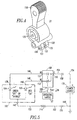
- An indicator such as'a dual LED indicator 102, includes a first indicator (e.g ., LED) 104 and a second indicator ( e.g. , LED) 106 (the two indicators 104,106 are shown in Figure 5).
- the first indicator 104 cooperates with the first output of the circuit 100 and is illuminated when the separable contacts 38,40 are open.
- the second indicator 106 cooperates with the second output of the circuit 100 and is illuminated when the separable contacts 38,40 are closed.
- the circuit 100 includes an auxiliary switch, such as a micro-switch 108, having an operating member, such as actuator 109, a common terminal 110, a normally open (NO) terminal 111 and a normally closed (NC) terminal 112 and, also, includes a resistor 114.
- the NO terminal 111 and the NC terminal 112 provide the first and second outputs, respectively, of the circuit 100.
- the housing 20 includes an opening 116 for the operating handle 22, which is employed to manually operate the operating mechanism 37.
- the operating handle 22 includes a first portion 118 extending through the housing opening 116 and a second portion 120 within the housing 20.
- the micro-switch actuator 109 cooperates with the operating mechanism 37 in general, and with the second portion 120 of the operating handle 22 in particular, in order to toggle the first and second outputs of the micro-switch 108.
- the housing 20 also includes an opening 122 through which an indicating portion 124 of the dual LED indicator 102 is suitably mounted ( e.g ., compression fit; held by lip 123 of LED indicator 102 and corresponding leads).
- the operating handle second portion 120 engages the micro-switch actuator 109 in the open ("off") position of the separable contacts 38,40. As shown in Figures 1 and 5, the operating handle second portion 120 disengages from the micro-switch actuator 109 in the closed ("on") position of the separable contacts 38,40.
- the actuated position of the actuator 109 provides the micro-switch first output (e.g ., the NO terminal 111 is electrically connected to the common terminal 110) for the open and tripped open positions of the separable contacts 38,40.
- the non-actuated position of the actuator 109 provides the micro-switch second output (e.g ., the NC terminal 112 is electrically connected to the common terminal 110) for the closed position of the separable contacts 38,40.
- the operating handle 22 includes the first and second portions 118,120, an opening 126 for the fixed pintle 52, an opening 128 for a pivot pin 129 (shown in Figures 1 and 2) for the link 32, and a pair of legs 130,131 with a space 132 therebetween to receive the link 32.
- the end of the leg 130 engages the micro-switch actuator 109 in the open ("off") position of the separable contacts 38,40.
- the common terminal 110 of the micro-switch 108 is adapted to receive a voltage 134 and, thus, be energized from a power supply, such as power source 136 (shown in phantom line drawing), which is external to the circuit breaker 10 of Figure 1.
- the dual LED 102 also includes two terminals 138,140, which are adapted to be energized through the micro-switch terminals 111,112, respectively, from the power source 136.
- the cathodes of the individual LEDs 104,106 are electrically connected within the dual LED 102, while the anodes of the individual LEDs 104,106 are electrically connected to the terminals 138,140, respectively.
- the dual LED 102 includes a third terminal 142, which, along with the LED cathodes, are electrically connected to the resistor 114, which, in turn, is adapted to be electrically interconnected with the common 144 of the power source 136.
- the anode of the first LED 104 is electrically connected to the NO terminal 111 of the micro-switch 108
- the anode of the second LED 106 is electrically connected to the NC terminal 112 of the micro-switch 108, which selectively energizes and illuminates one of the LEDs 104,106 from the voltage 134 of the power source 136 at common terminal 110 and back through the resistor 114 to the power source common 144.
- a resistor may be electrically interconnected between the voltage 134 of the power source 136 and the micro-switch common terminal 110 in addition to, or in place of, the resistor 114.
- a first conductor 146 from the LED 104 of the dual LED 102 is electrically connected to the micro-switch NO terminal 111.
- a second conductor 148 from the LED 106 of the dual LED 102 is electrically connected to the micro-switch NC terminal 112.
- a third conductor 150 from the cathodes of the dual LED 102 is electrically connected to the resistor 114, in order to limit the LED current and, thereby, prevent the dual LED from burning out.
- the resistor 114 is electrically interconnected by a fourth conductor 152 with the common 144 of the power source 136.
- the micro-switch common terminal 110 is electrically interconnected by a fifth conductor 154 with the voltage 134 of the power source 136.
- the conductors 146,148,150,152,154 are electrically insulated.
- the conductors 152,154 include suitable terminations, such as 156,158, respectively, of Figure 5 for suitable electrical connection to the external power source 136.
- the auxiliary micro-switch 108 is set internal to the circuit breaker 10. As the circuit breaker 10 is toggled between “off” (or the tripped “off") and the “on” positions, the dual LED 102 is toggled back and forth between a green light, which indicates “off” or tripped “off', and a red light, which indicates that the circuit breaker is "on”.
- LED indicators 104,106 in a dual LED package 102 are disclosed, the invention is applicable to any suitable indicator(s), which may be suitably illuminated to show the open and closed positions of separable contacts, such as 38,40.
- any suitable illuminable indicator(s) and combinations thereof may be employed (e.g., a dual indicator; two individual indicators; lamp(s), light(s); any suitable illuminating device(s)).
- the first indicator 104 has a first color (e.g., green; any suitable color), and the second indicator 106 has a second different color (eg., red; any suitable color). It will be appreciated that these colors may be swapped or that a wide range of suitable colors may be employed.
- one of the indicators 104,106 may employ a suitable color, and the other one of the indicators 104,106 may employ the same suitable color, which is illuminated with a suitable on/off modulation by a suitable circuit (not shown).
- a single indicator (not shown) may be employed which is illuminated in a suitable color for one of the "on” and “off” positions, and is illuminated in the same suitable color with a suitable on/off modulation by a suitable circuit (not shown) for the other one of the "on” and “off” positions.
- a third indicator may be employed for the tripped "off" position.
- any suitable circuit and/or mechanism may be provided in order to provide outputs corresponding to the open and closed states of separable contacts.
- one indicator may illuminate for the tripped open state and another indicator may illuminate for the not tripped open state (e.g ., open or closed) with the linkage 30 being unbroken.
- circuit breakers and other electrical switching devices having any count of poles and with or without a suitable trip mechanism (e.g., hydraulic; electromagnetic; magnetic; thermal).
- a suitable trip mechanism e.g., hydraulic; electromagnetic; magnetic; thermal.
Landscapes
- Breakers (AREA)
- Switch Cases, Indication, And Locking (AREA)
- Driving Mechanisms And Operating Circuits Of Arc-Extinguishing High-Tension Switches (AREA)
Applications Claiming Priority (2)
| Application Number | Priority Date | Filing Date | Title |
|---|---|---|---|
| US650343 | 2003-08-28 | ||
| US10/650,343 US6864447B1 (en) | 2003-08-28 | 2003-08-28 | Circuit breaker empolying illuminating indicators for open and closed positions |
Publications (3)
| Publication Number | Publication Date |
|---|---|
| EP1511056A2 true EP1511056A2 (fr) | 2005-03-02 |
| EP1511056A3 EP1511056A3 (fr) | 2007-05-16 |
| EP1511056B1 EP1511056B1 (fr) | 2011-12-21 |
Family
ID=34104700
Family Applications (1)
| Application Number | Title | Priority Date | Filing Date |
|---|---|---|---|
| EP04018235A Expired - Lifetime EP1511056B1 (fr) | 2003-08-28 | 2004-08-02 | Disjoncteur avec indicateurs lumineux pour les positions d' ouverture et de fermeture |
Country Status (8)
| Country | Link |
|---|---|
| US (1) | US6864447B1 (fr) |
| EP (1) | EP1511056B1 (fr) |
| CN (1) | CN100447918C (fr) |
| AT (1) | ATE538485T1 (fr) |
| BR (1) | BRPI0403382A (fr) |
| CA (1) | CA2478695C (fr) |
| ES (1) | ES2375474T3 (fr) |
| ZA (1) | ZA200406806B (fr) |
Cited By (5)
| Publication number | Priority date | Publication date | Assignee | Title |
|---|---|---|---|---|
| GB2439108A (en) * | 2006-06-13 | 2007-12-19 | Fung Yip Electrical Mfg Ltd | Light switch system |
| DE102012201552A1 (de) * | 2012-02-02 | 2013-08-08 | Siemens Aktiengesellschaft | Elektrischer Schalter |
| US20140070953A1 (en) * | 2012-09-13 | 2014-03-13 | Schneider Electric Industries Sas | Relay and a method for indicating a relay failure |
| CN105788975A (zh) * | 2016-02-26 | 2016-07-20 | 电卫士智能电器(北京)有限公司 | 断路器监测装置、断路器以及断路器监测方法 |
| EP2568489B1 (fr) | 2011-09-07 | 2018-07-11 | Siemens Aktiengesellschaft | Disjoncteur électrique avec un dispositif d'affichage d'état |
Families Citing this family (27)
| Publication number | Priority date | Publication date | Assignee | Title |
|---|---|---|---|---|
| US7569785B2 (en) * | 2005-05-16 | 2009-08-04 | Eaton Corporation | Electrical switching apparatus indicating status through panel aperture |
| US7369022B2 (en) * | 2006-01-23 | 2008-05-06 | Eaton Corporation | Auxiliary switch sub-assembly and electrical switching apparatus employing the same |
| US7319373B2 (en) * | 2006-01-23 | 2008-01-15 | Eaton Corporation | Electrical switching apparatus and terminal housing therefor |
| JP2007299727A (ja) * | 2006-04-07 | 2007-11-15 | Fuji Electric Fa Components & Systems Co Ltd | 漏電遮断器 |
| KR100890754B1 (ko) * | 2007-07-12 | 2009-03-26 | 엘에스산전 주식회사 | 기중 차단기용 투입작동 가능 표시장치 및 이를 갖는 기중차단기 |
| CN101188176B (zh) * | 2007-11-27 | 2010-08-11 | Tcl低压电器(无锡)有限公司 | 能正确显示塑壳断路器触头合分的装置 |
| US9263217B2 (en) * | 2010-02-23 | 2016-02-16 | Abb Technology, Ag | Protective switch with status detection |
| USD645006S1 (en) * | 2010-02-24 | 2011-09-13 | Schaltbau Gmbh | Toggle switch |
| US9455111B2 (en) * | 2012-10-17 | 2016-09-27 | Abb Inc. | Method and structure for monitoring breaker status contacts on circuit breaker applications |
| US9859084B2 (en) * | 2013-09-12 | 2018-01-02 | Carling Technologies, Inc. | Remote operated circuit breaker with manual reset |
| US20150262768A1 (en) * | 2014-03-11 | 2015-09-17 | Thomas & Betts International, Llc | Switchgear having visible break window |
| US9620303B2 (en) * | 2014-08-13 | 2017-04-11 | Eaton Corporation | Circuit breakers with handle bearing pins |
| FR3029347B1 (fr) * | 2014-12-02 | 2016-12-02 | Schneider Electric Ind Sas | Systeme de commande d'une charge electrique |
| KR102513352B1 (ko) * | 2016-02-25 | 2023-03-23 | 엘에스일렉트릭(주) | 상태표시기능을 갖는 상입형 전자개폐기 |
| CA3021488C (fr) * | 2016-05-09 | 2022-03-08 | John J. O'connor | Disjoncteur a temoin lumineux de declenchement |
| CN113257634A (zh) * | 2016-08-05 | 2021-08-13 | 立维腾制造有限公司 | 结合复位锁定机构的断路器 |
| KR101869724B1 (ko) * | 2017-01-05 | 2018-06-21 | 엘에스산전 주식회사 | 회로차단기의 전자 트립 장치 |
| KR102299858B1 (ko) * | 2017-03-15 | 2021-09-08 | 엘에스일렉트릭 (주) | 회로차단기의 전자 트립 장치 |
| CN107221870B (zh) * | 2017-07-04 | 2023-04-07 | 兴机电器有限公司 | 一种具有位置指示功能的断路器底盘车 |
| US10468219B2 (en) * | 2017-09-07 | 2019-11-05 | Carling Technologies, Inc. | Circuit interrupter with status indication |
| EP3561849B1 (fr) * | 2018-04-23 | 2023-03-08 | ABB S.p.A. | Disjoncteur |
| US10984974B2 (en) * | 2018-12-20 | 2021-04-20 | Schneider Electric USA, Inc. | Line side power, double break, switch neutral electronic circuit breaker |
| US11610751B2 (en) | 2019-12-09 | 2023-03-21 | Leviton Manufacturing Co., Inc. | Circuit breakers incorporating reset lockout mechanisms |
| US12505970B2 (en) | 2021-02-19 | 2025-12-23 | Leviton Manufacturing Co., Inc. | Circuit breaker including a remote on/off breaker |
| CN113205978A (zh) * | 2021-04-01 | 2021-08-03 | 浙江天正电气股份有限公司 | 一种内置辅助功能的断路器及其报警系统 |
| CN116364486A (zh) * | 2021-12-27 | 2023-06-30 | 上海良信电器股份有限公司 | 一种断路器 |
| CN114551184B (zh) * | 2022-03-03 | 2023-06-13 | 浙江习羽智能科技有限公司 | 一种智能脱扣器 |
Family Cites Families (24)
| Publication number | Priority date | Publication date | Assignee | Title |
|---|---|---|---|---|
| US3329913A (en) | 1966-01-28 | 1967-07-04 | Heinemann Electric Co | Circuit breaker mechanism |
| US3319034A (en) * | 1966-03-03 | 1967-05-09 | Westinghouse Electric Corp | Circuit breaker having means for readily indicating the position thereof |
| US3742402A (en) | 1970-10-01 | 1973-06-26 | Heinemann Electric Co | Circuit breaker with on off and trip indication |
| US3742403A (en) | 1970-10-01 | 1973-06-26 | Heinemann Electric Co | Circuit breaker with on off and trip indication |
| US3806848A (en) | 1972-11-06 | 1974-04-23 | J Shand | Snap action breaker with housing |
| US3955162A (en) | 1973-08-01 | 1976-05-04 | Heinemann Electric Company | Electromagnetic circuit breaker with electrical and mechanical trip indication |
| US3863042A (en) | 1973-08-01 | 1975-01-28 | Heinemann Electric Co | Circuit breaker with electrical and mechanical trip indication |
| US4267539A (en) | 1979-08-02 | 1981-05-12 | Heinemann Electric Company | Circuit breaker having a cam for external adjustment of its trip point |
| US4344100A (en) * | 1980-08-07 | 1982-08-10 | Westinghouse Electric Corp. | Ground fault circuit breaker with ground fault trip indicator |
| US4768025A (en) * | 1984-09-25 | 1988-08-30 | Vila Masot Oscar | Circuit breaker indicator |
| CN1004311B (zh) * | 1985-06-13 | 1989-05-24 | 奥斯卡·维拉·梅索 | 线路断路器的显示器 |
| US4926148A (en) | 1988-10-03 | 1990-05-15 | Heinemann Electric Company | Auxiliary switch retainer for circuit breakers and actuator member |
| US4963847A (en) | 1989-04-11 | 1990-10-16 | Heinemann Electric Company | Circuit breaker with transparent tube magnetic core holder |
| US4969063A (en) * | 1989-05-16 | 1990-11-06 | Square D Company | Circuit breaker with status indicating lights |
| US5301083A (en) * | 1991-09-30 | 1994-04-05 | Eaton Corporation | Remote control residential circuit breaker |
| US5546266A (en) | 1994-06-24 | 1996-08-13 | Eaton Corporation | Circuit interrupter with cause for trip indication |
| US5847913A (en) | 1997-02-21 | 1998-12-08 | Square D Company | Trip indicators for circuit protection devices |
| US6031438A (en) * | 1998-10-16 | 2000-02-29 | Airpax Corporation, Llc | Mid trip stop for circuit breaker |
| US6246304B1 (en) * | 1999-03-26 | 2001-06-12 | Airpax Corporation, Llc | Trip indicating circuit breaker |
| US6075215A (en) | 1999-03-29 | 2000-06-13 | Siemens Energy & Automation, Inc. | Light pipe indicator assembly for a stored energy circuit breaker operator assembly |
| US6342995B1 (en) * | 2000-03-02 | 2002-01-29 | Instrument Transformers, Inc. | Lighted escutcheon plate for power distribution equipment |
| US6365855B1 (en) | 2000-03-28 | 2002-04-02 | Thomson Licensing S.A. | Illuminated button |
| US6724284B2 (en) * | 2001-02-02 | 2004-04-20 | Eaton Corporation | Circuit breaker |
| US6542056B2 (en) | 2001-04-30 | 2003-04-01 | Eaton Corporation | Circuit breaker having a movable and illuminable arc fault indicator |
-
2003
- 2003-08-28 US US10/650,343 patent/US6864447B1/en not_active Expired - Lifetime
-
2004
- 2004-08-02 ES ES04018235T patent/ES2375474T3/es not_active Expired - Lifetime
- 2004-08-02 AT AT04018235T patent/ATE538485T1/de active
- 2004-08-02 EP EP04018235A patent/EP1511056B1/fr not_active Expired - Lifetime
- 2004-08-12 BR BR0403382-5A patent/BRPI0403382A/pt not_active IP Right Cessation
- 2004-08-20 CA CA2478695A patent/CA2478695C/fr not_active Expired - Fee Related
- 2004-08-26 ZA ZA2004/06806A patent/ZA200406806B/en unknown
- 2004-08-27 CN CNB200410073901XA patent/CN100447918C/zh not_active Expired - Fee Related
Cited By (8)
| Publication number | Priority date | Publication date | Assignee | Title |
|---|---|---|---|---|
| GB2439108A (en) * | 2006-06-13 | 2007-12-19 | Fung Yip Electrical Mfg Ltd | Light switch system |
| EP2568489B1 (fr) | 2011-09-07 | 2018-07-11 | Siemens Aktiengesellschaft | Disjoncteur électrique avec un dispositif d'affichage d'état |
| DE102012201552A1 (de) * | 2012-02-02 | 2013-08-08 | Siemens Aktiengesellschaft | Elektrischer Schalter |
| US20140070953A1 (en) * | 2012-09-13 | 2014-03-13 | Schneider Electric Industries Sas | Relay and a method for indicating a relay failure |
| EP2709136A1 (fr) * | 2012-09-13 | 2014-03-19 | Schneider Electric Industries SAS | Relais et procédé d'indication d'une erreur de relais |
| US9543098B2 (en) | 2012-09-13 | 2017-01-10 | Schneider Electric Industries Sas | Relay and a method for indicating a relay failure |
| CN105788975A (zh) * | 2016-02-26 | 2016-07-20 | 电卫士智能电器(北京)有限公司 | 断路器监测装置、断路器以及断路器监测方法 |
| CN105788975B (zh) * | 2016-02-26 | 2019-07-02 | 电卫士智能电器(北京)有限公司 | 断路器监测装置、断路器以及断路器监测方法 |
Also Published As
| Publication number | Publication date |
|---|---|
| CA2478695A1 (fr) | 2005-02-28 |
| EP1511056B1 (fr) | 2011-12-21 |
| CN100447918C (zh) | 2008-12-31 |
| BRPI0403382A (pt) | 2005-05-31 |
| US20050046526A1 (en) | 2005-03-03 |
| CN1591725A (zh) | 2005-03-09 |
| EP1511056A3 (fr) | 2007-05-16 |
| ATE538485T1 (de) | 2012-01-15 |
| US6864447B1 (en) | 2005-03-08 |
| CA2478695C (fr) | 2013-05-14 |
| ES2375474T3 (es) | 2012-03-01 |
| ZA200406806B (en) | 2005-08-31 |
Similar Documents
| Publication | Publication Date | Title |
|---|---|---|
| CA2478695C (fr) | Disjoncteur comprenant des voyants lumineux de position ouverte et de position fermee | |
| US6903289B2 (en) | Circuit breaker employing an illuminated operating handle | |
| US6710688B2 (en) | Circuit breaker | |
| US6522228B2 (en) | Circuit breaker including an arc fault trip actuator having an indicator latch and a trip latch | |
| US6542056B2 (en) | Circuit breaker having a movable and illuminable arc fault indicator | |
| JP2894052B2 (ja) | 回路遮断器 | |
| US6215378B1 (en) | Circuit breaker with dual function test button remote from test circuit | |
| KR100462657B1 (ko) | 회로차단기 | |
| US4987395A (en) | Circuit breaker alarm-switch operating apparatus | |
| AU2004201267B2 (en) | Remotely controllable circuit breaker including bypass magnet circuit | |
| CA2437111C (fr) | Disjoncteur | |
| AU2004203223B2 (en) | Circuit breaker trip unit employing a rotary plunger | |
| CA2338667C (fr) | Disjoncteur telecommandable avec systeme combine d'indicateur visuel d'etat et de commande manuelle de surpassement | |
| JPH0243083Y2 (fr) | ||
| AU2002226629A1 (en) | Circuit breaker | |
| JPS59128726A (ja) | リモ−トコントロ−ル式回路しや断器 |
Legal Events
| Date | Code | Title | Description |
|---|---|---|---|
| PUAI | Public reference made under article 153(3) epc to a published international application that has entered the european phase |
Free format text: ORIGINAL CODE: 0009012 |
|
| AK | Designated contracting states |
Kind code of ref document: A2 Designated state(s): AT BE BG CH CY CZ DE DK EE ES FI FR GB GR HU IE IT LI LU MC NL PL PT RO SE SI SK TR |
|
| AX | Request for extension of the european patent |
Extension state: AL HR LT LV MK |
|
| PUAL | Search report despatched |
Free format text: ORIGINAL CODE: 0009013 |
|
| AK | Designated contracting states |
Kind code of ref document: A3 Designated state(s): AT BE BG CH CY CZ DE DK EE ES FI FR GB GR HU IE IT LI LU MC NL PL PT RO SE SI SK TR |
|
| AX | Request for extension of the european patent |
Extension state: AL HR LT LV MK |
|
| 17P | Request for examination filed |
Effective date: 20070913 |
|
| AKX | Designation fees paid |
Designated state(s): AT BE BG CH CY CZ DE DK EE ES FI FR GB GR HU IE IT LI LU MC NL PL PT RO SE SI SK TR |
|
| 17Q | First examination report despatched |
Effective date: 20100409 |
|
| GRAP | Despatch of communication of intention to grant a patent |
Free format text: ORIGINAL CODE: EPIDOSNIGR1 |
|
| GRAS | Grant fee paid |
Free format text: ORIGINAL CODE: EPIDOSNIGR3 |
|
| GRAA | (expected) grant |
Free format text: ORIGINAL CODE: 0009210 |
|
| AK | Designated contracting states |
Kind code of ref document: B1 Designated state(s): AT BE BG CH CY CZ DE DK EE ES FI FR GB GR HU IE IT LI LU MC NL PL PT RO SE SI SK TR |
|
| REG | Reference to a national code |
Ref country code: GB Ref legal event code: FG4D |
|
| REG | Reference to a national code |
Ref country code: CH Ref legal event code: EP |
|
| REG | Reference to a national code |
Ref country code: AT Ref legal event code: REF Ref document number: 538485 Country of ref document: AT Kind code of ref document: T Effective date: 20120115 |
|
| REG | Reference to a national code |
Ref country code: IE Ref legal event code: FG4D |
|
| REG | Reference to a national code |
Ref country code: SE Ref legal event code: TRGR |
|
| REG | Reference to a national code |
Ref country code: ES Ref legal event code: FG2A Ref document number: 2375474 Country of ref document: ES Kind code of ref document: T3 Effective date: 20120301 |
|
| REG | Reference to a national code |
Ref country code: DE Ref legal event code: R096 Ref document number: 602004035729 Country of ref document: DE Effective date: 20120308 |
|
| REG | Reference to a national code |
Ref country code: NL Ref legal event code: VDEP Effective date: 20111221 |
|
| PG25 | Lapsed in a contracting state [announced via postgrant information from national office to epo] |
Ref country code: GR Free format text: LAPSE BECAUSE OF FAILURE TO SUBMIT A TRANSLATION OF THE DESCRIPTION OR TO PAY THE FEE WITHIN THE PRESCRIBED TIME-LIMIT Effective date: 20120322 Ref country code: SI Free format text: LAPSE BECAUSE OF FAILURE TO SUBMIT A TRANSLATION OF THE DESCRIPTION OR TO PAY THE FEE WITHIN THE PRESCRIBED TIME-LIMIT Effective date: 20111221 Ref country code: NL Free format text: LAPSE BECAUSE OF FAILURE TO SUBMIT A TRANSLATION OF THE DESCRIPTION OR TO PAY THE FEE WITHIN THE PRESCRIBED TIME-LIMIT Effective date: 20111221 |
|
| PG25 | Lapsed in a contracting state [announced via postgrant information from national office to epo] |
Ref country code: BE Free format text: LAPSE BECAUSE OF FAILURE TO SUBMIT A TRANSLATION OF THE DESCRIPTION OR TO PAY THE FEE WITHIN THE PRESCRIBED TIME-LIMIT Effective date: 20111221 Ref country code: CY Free format text: LAPSE BECAUSE OF FAILURE TO SUBMIT A TRANSLATION OF THE DESCRIPTION OR TO PAY THE FEE WITHIN THE PRESCRIBED TIME-LIMIT Effective date: 20111221 |
|
| PG25 | Lapsed in a contracting state [announced via postgrant information from national office to epo] |
Ref country code: BG Free format text: LAPSE BECAUSE OF FAILURE TO SUBMIT A TRANSLATION OF THE DESCRIPTION OR TO PAY THE FEE WITHIN THE PRESCRIBED TIME-LIMIT Effective date: 20120321 Ref country code: CZ Free format text: LAPSE BECAUSE OF FAILURE TO SUBMIT A TRANSLATION OF THE DESCRIPTION OR TO PAY THE FEE WITHIN THE PRESCRIBED TIME-LIMIT Effective date: 20111221 Ref country code: SK Free format text: LAPSE BECAUSE OF FAILURE TO SUBMIT A TRANSLATION OF THE DESCRIPTION OR TO PAY THE FEE WITHIN THE PRESCRIBED TIME-LIMIT Effective date: 20111221 Ref country code: EE Free format text: LAPSE BECAUSE OF FAILURE TO SUBMIT A TRANSLATION OF THE DESCRIPTION OR TO PAY THE FEE WITHIN THE PRESCRIBED TIME-LIMIT Effective date: 20111221 |
|
| PG25 | Lapsed in a contracting state [announced via postgrant information from national office to epo] |
Ref country code: PL Free format text: LAPSE BECAUSE OF FAILURE TO SUBMIT A TRANSLATION OF THE DESCRIPTION OR TO PAY THE FEE WITHIN THE PRESCRIBED TIME-LIMIT Effective date: 20111221 Ref country code: RO Free format text: LAPSE BECAUSE OF FAILURE TO SUBMIT A TRANSLATION OF THE DESCRIPTION OR TO PAY THE FEE WITHIN THE PRESCRIBED TIME-LIMIT Effective date: 20111221 Ref country code: PT Free format text: LAPSE BECAUSE OF FAILURE TO SUBMIT A TRANSLATION OF THE DESCRIPTION OR TO PAY THE FEE WITHIN THE PRESCRIBED TIME-LIMIT Effective date: 20120423 |
|
| REG | Reference to a national code |
Ref country code: AT Ref legal event code: MK05 Ref document number: 538485 Country of ref document: AT Kind code of ref document: T Effective date: 20111221 |
|
| PLBE | No opposition filed within time limit |
Free format text: ORIGINAL CODE: 0009261 |
|
| STAA | Information on the status of an ep patent application or granted ep patent |
Free format text: STATUS: NO OPPOSITION FILED WITHIN TIME LIMIT |
|
| PG25 | Lapsed in a contracting state [announced via postgrant information from national office to epo] |
Ref country code: DK Free format text: LAPSE BECAUSE OF FAILURE TO SUBMIT A TRANSLATION OF THE DESCRIPTION OR TO PAY THE FEE WITHIN THE PRESCRIBED TIME-LIMIT Effective date: 20111221 |
|
| PGFP | Annual fee paid to national office [announced via postgrant information from national office to epo] |
Ref country code: SE Payment date: 20120809 Year of fee payment: 9 |
|
| 26N | No opposition filed |
Effective date: 20120924 |
|
| PGFP | Annual fee paid to national office [announced via postgrant information from national office to epo] |
Ref country code: ES Payment date: 20120814 Year of fee payment: 9 |
|
| REG | Reference to a national code |
Ref country code: DE Ref legal event code: R097 Ref document number: 602004035729 Country of ref document: DE Effective date: 20120924 |
|
| PG25 | Lapsed in a contracting state [announced via postgrant information from national office to epo] |
Ref country code: AT Free format text: LAPSE BECAUSE OF FAILURE TO SUBMIT A TRANSLATION OF THE DESCRIPTION OR TO PAY THE FEE WITHIN THE PRESCRIBED TIME-LIMIT Effective date: 20111221 |
|
| REG | Reference to a national code |
Ref country code: CH Ref legal event code: PL |
|
| PG25 | Lapsed in a contracting state [announced via postgrant information from national office to epo] |
Ref country code: MC Free format text: LAPSE BECAUSE OF NON-PAYMENT OF DUE FEES Effective date: 20120831 |
|
| PG25 | Lapsed in a contracting state [announced via postgrant information from national office to epo] |
Ref country code: LI Free format text: LAPSE BECAUSE OF NON-PAYMENT OF DUE FEES Effective date: 20120831 Ref country code: CH Free format text: LAPSE BECAUSE OF NON-PAYMENT OF DUE FEES Effective date: 20120831 |
|
| REG | Reference to a national code |
Ref country code: IE Ref legal event code: MM4A |
|
| PG25 | Lapsed in a contracting state [announced via postgrant information from national office to epo] |
Ref country code: FI Free format text: LAPSE BECAUSE OF FAILURE TO SUBMIT A TRANSLATION OF THE DESCRIPTION OR TO PAY THE FEE WITHIN THE PRESCRIBED TIME-LIMIT Effective date: 20111221 |
|
| PG25 | Lapsed in a contracting state [announced via postgrant information from national office to epo] |
Ref country code: IE Free format text: LAPSE BECAUSE OF NON-PAYMENT OF DUE FEES Effective date: 20120802 |
|
| REG | Reference to a national code |
Ref country code: SE Ref legal event code: EUG |
|
| PG25 | Lapsed in a contracting state [announced via postgrant information from national office to epo] |
Ref country code: SE Free format text: LAPSE BECAUSE OF NON-PAYMENT OF DUE FEES Effective date: 20130803 Ref country code: TR Free format text: LAPSE BECAUSE OF FAILURE TO SUBMIT A TRANSLATION OF THE DESCRIPTION OR TO PAY THE FEE WITHIN THE PRESCRIBED TIME-LIMIT Effective date: 20111221 |
|
| PG25 | Lapsed in a contracting state [announced via postgrant information from national office to epo] |
Ref country code: LU Free format text: LAPSE BECAUSE OF NON-PAYMENT OF DUE FEES Effective date: 20120802 |
|
| PG25 | Lapsed in a contracting state [announced via postgrant information from national office to epo] |
Ref country code: HU Free format text: LAPSE BECAUSE OF FAILURE TO SUBMIT A TRANSLATION OF THE DESCRIPTION OR TO PAY THE FEE WITHIN THE PRESCRIBED TIME-LIMIT Effective date: 20040802 |
|
| REG | Reference to a national code |
Ref country code: ES Ref legal event code: FD2A Effective date: 20140905 |
|
| PG25 | Lapsed in a contracting state [announced via postgrant information from national office to epo] |
Ref country code: ES Free format text: LAPSE BECAUSE OF NON-PAYMENT OF DUE FEES Effective date: 20130803 |
|
| REG | Reference to a national code |
Ref country code: FR Ref legal event code: PLFP Year of fee payment: 13 |
|
| REG | Reference to a national code |
Ref country code: FR Ref legal event code: PLFP Year of fee payment: 14 |
|
| REG | Reference to a national code |
Ref country code: FR Ref legal event code: PLFP Year of fee payment: 15 |
|
| REG | Reference to a national code |
Ref country code: GB Ref legal event code: 732E Free format text: REGISTERED BETWEEN 20181115 AND 20181130 |
|
| REG | Reference to a national code |
Ref country code: DE Ref legal event code: R082 Ref document number: 602004035729 Country of ref document: DE Ref country code: DE Ref legal event code: R081 Ref document number: 602004035729 Country of ref document: DE Owner name: EATON INTELLIGENT POWER LIMITED, IE Free format text: FORMER OWNER: EATON CORPORATION, CLEVELAND, OHIO, US |
|
| PGFP | Annual fee paid to national office [announced via postgrant information from national office to epo] |
Ref country code: DE Payment date: 20190722 Year of fee payment: 16 Ref country code: FR Payment date: 20190722 Year of fee payment: 16 Ref country code: IT Payment date: 20190722 Year of fee payment: 16 |
|
| PGFP | Annual fee paid to national office [announced via postgrant information from national office to epo] |
Ref country code: GB Payment date: 20190722 Year of fee payment: 16 |
|
| REG | Reference to a national code |
Ref country code: DE Ref legal event code: R119 Ref document number: 602004035729 Country of ref document: DE |
|
| GBPC | Gb: european patent ceased through non-payment of renewal fee |
Effective date: 20200802 |
|
| PG25 | Lapsed in a contracting state [announced via postgrant information from national office to epo] |
Ref country code: IT Free format text: LAPSE BECAUSE OF NON-PAYMENT OF DUE FEES Effective date: 20200802 Ref country code: FR Free format text: LAPSE BECAUSE OF NON-PAYMENT OF DUE FEES Effective date: 20200831 Ref country code: DE Free format text: LAPSE BECAUSE OF NON-PAYMENT OF DUE FEES Effective date: 20210302 |
|
| PG25 | Lapsed in a contracting state [announced via postgrant information from national office to epo] |
Ref country code: GB Free format text: LAPSE BECAUSE OF NON-PAYMENT OF DUE FEES Effective date: 20200802 |