EP1511044A2 - Method of making a conductive fire-retardant thermoplastic mixture - Google Patents
Method of making a conductive fire-retardant thermoplastic mixture Download PDFInfo
- Publication number
- EP1511044A2 EP1511044A2 EP04025613A EP04025613A EP1511044A2 EP 1511044 A2 EP1511044 A2 EP 1511044A2 EP 04025613 A EP04025613 A EP 04025613A EP 04025613 A EP04025613 A EP 04025613A EP 1511044 A2 EP1511044 A2 EP 1511044A2
- Authority
- EP
- European Patent Office
- Prior art keywords
- conductive
- conductive elements
- recited
- mixture
- bundle
- Prior art date
- Legal status (The legal status is an assumption and is not a legal conclusion. Google has not performed a legal analysis and makes no representation as to the accuracy of the status listed.)
- Withdrawn
Links
Images

Classifications
-
- H—ELECTRICITY
- H01—ELECTRIC ELEMENTS
- H01B—CABLES; CONDUCTORS; INSULATORS; SELECTION OF MATERIALS FOR THEIR CONDUCTIVE, INSULATING OR DIELECTRIC PROPERTIES
- H01B7/00—Insulated conductors or cables characterised by their form
- H01B7/17—Protection against damage caused by external factors, e.g. sheaths or armouring
- H01B7/29—Protection against damage caused by extremes of temperature or by flame
- H01B7/295—Protection against damage caused by extremes of temperature or by flame using material resistant to flame
-
- C—CHEMISTRY; METALLURGY
- C09—DYES; PAINTS; POLISHES; NATURAL RESINS; ADHESIVES; COMPOSITIONS NOT OTHERWISE PROVIDED FOR; APPLICATIONS OF MATERIALS NOT OTHERWISE PROVIDED FOR
- C09K—MATERIALS FOR MISCELLANEOUS APPLICATIONS, NOT PROVIDED FOR ELSEWHERE
- C09K21/00—Fireproofing materials
-
- H—ELECTRICITY
- H01—ELECTRIC ELEMENTS
- H01B—CABLES; CONDUCTORS; INSULATORS; SELECTION OF MATERIALS FOR THEIR CONDUCTIVE, INSULATING OR DIELECTRIC PROPERTIES
- H01B1/00—Conductors or conductive bodies characterised by the conductive materials; Selection of materials as conductors
- H01B1/20—Conductive material dispersed in non-conductive organic material
- H01B1/22—Conductive material dispersed in non-conductive organic material the conductive material comprising metals or alloys
-
- H—ELECTRICITY
- H01—ELECTRIC ELEMENTS
- H01B—CABLES; CONDUCTORS; INSULATORS; SELECTION OF MATERIALS FOR THEIR CONDUCTIVE, INSULATING OR DIELECTRIC PROPERTIES
- H01B1/00—Conductors or conductive bodies characterised by the conductive materials; Selection of materials as conductors
- H01B1/20—Conductive material dispersed in non-conductive organic material
- H01B1/24—Conductive material dispersed in non-conductive organic material the conductive material comprising carbon-silicon compounds, carbon or silicon
Definitions
- This invention relates to plastic materials and, more particularly, to a conductive, fire-retardant, thermoplastic elastomer mixture.
- conductive plastic parts are utilized in electronic assemblies.
- conductive plastic parts are often employed for grounding, static discharge and electromagnetic interference (EMI) shielding purposes.
- Typical parts made of conductive plastic in electronic assemblies include grounding grommets, conductive gaskets, flexible grounding straps, protective boots and face-plate panels for circuit packages.
- An exemplary two-part unitary panel comprises an electrically non-conductive rigid plastic part combined with an electrically conductive plastic part that serves as a flexible gasket.
- the panel is utilized to seal an opening in an electronic assembly to reduce the passage of EMI through the enclosure opening.
- JP-A-59 155 448 is directed to a flame-retardant resin composition. having high electromagnetic wave shielding power and good processability and moldability.
- the composition consists of a thermoplastic resin, an aluminum or aluminum alloy, electrically conductive carbon black, a halogen-containing organic compound, antimony oxide and a hydrated inorganic material.
- the thermoplastic resin is selected among: a styrene containing polymer; a polymer obtained by treating a high molecular weight material selected from rubbery materials and polyphenylene ether with a monomer group containing styrene; and a mixture of the styrene containing polymer and high-molecular weight material.
- EP-A-0 137 290 is directed to a resin composition having an electromagnetic wave shielding effect.
- the resin composition comprises 35 to 90 wt % of an ABS resin or a mixture of the ABS resin and an AS resin, 1 to 25 wt % of a plasticizer and 5 to 40 wt % of carbon fibers.
- the carbon fibers are uniformly dispersed in the resin ingredient without being broken or cut at the step of mixing and dispersing the resin components, thus exhibiting improved electromagnetic wave shielding effect.
- the carbon fibers are one or a mixture of two or more of carbonized polyacrylonitrile fibers, carbonized pitch fibers and carbonized phenolic compound fibers. (Page 12, Lines 5-7).
- the fibers can have a broad range of preferred diameters (5 to 12 microns), lengths (2 to 20 mm) and bundle counts (1000 to 20000).
- a method according to the invention is as set out in claim 1. Preferred forms are set out in the dependent claims.
- a conductive soft-durometer fire-retardant thermoplastic mixture comprises a base thermoplastic elastomer material combined with a fire-retardant material and a matrix of small-diameter conductive fibers.
- the mixture includes a styrene-ethylene-butylene-styrene (SEBS) plastic material combined with antimony trioxide and metal-coated graphite fibers.
- SEBS styrene-ethylene-butylene-styrene
- antimony trioxide comprises about 10-to-20 per cent by volume of the mixture and the metal-coated graphite fibers comprise approximately 5-to-25 per cent by volume of the mixture, with the base elastomer material comprising the remaining volume of the mixture.
- FIG. 1 illustrates one particular example of a portion of an electronic assembly that includes a plastic part made in accordance with the principles of the present invention.
- FIG. 1 shows a two-part panel 10 that comprises a front electrically non-conductive part 20 bonded to a back conductive shield or gasket part 30.
- the two-part panel 10 is similar to the panel 10 described in the introduction.
- the part 30 shown in FIG. 1 is formed of a material made using the principles of the present invention. This unique material comprises a conductive soft-durometer synthetic rubber that is fire-retardant.
- one component of this mixture comprises a standard base thermoplastic elastomer commonly known as styrene-ethylene-butylene-styrene (SEBS) material. More specifically, this material advantageously comprises, for example, a conventional SEBS material such as Shell Kraton material, which is readily available from a chemical supplier such as Shell Chemical Co., 1 Shell Plaza, Houston, Texas 77002. Illustratively, the elastomer is supplied in pellet form, each pellet measuring about 0.32 centimeters (cm) in length and having a diameter of approximately 0.32 cm.
- SEBS standard base thermoplastic elastomer commonly known as styrene-ethylene-butylene-styrene
- the second component of the inventive mixture comprises conductive elements.
- each of these elements comprises a metal-coated graphite fiber.
- Other conductive elements such as metal flakes or metal-coated mica are also feasible.
- FIG. 2 a front face view of a conventional metal-coated graphite fiber 40 is shown in FIG. 2.
- the overall diameter D1 of the FIG. 2 fiber is only about six micrometers ( ⁇ m).
- the illustrative coated fiber 40 of FIG. 2 includes, for example, a four- ⁇ m-diameter graphite core 42. To enhance the electrical conductivity of the core 42, it is advantageous to coat the core with one or more layers of a relatively high-conductivity material.
- the particular fiber 40 of FIG. 2 is shown as having layers 44 through 46 formed thereon.
- the layers 44 through 46 respectively comprise: a 0.15- ⁇ m-thick layer of nickel, a 0.1- ⁇ m-thick layer of copper and a 0.15- ⁇ m-thick layer of nickel.
- the diameter of an individual coated fiber such as the fiber 40 depicted in FIG. 2 is extremely small. In practice, it has been found that handling such fine fibers and achieving even distribution of them in the final mixture is extremely difficult. Thus, in accordance with the invention, it is advantageous to utilize fiber bundles rather than individual fibers as one of the starting components of the mixture.
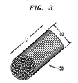
- FIG. 3 represents such a bundle 50 of fibers.
- Each individual fiber in the bundle is of the type shown in FIG. 2.
- Such bundles are commonly known and are available from, for example, a commercial supplier such as Composite Materials Inc., 700 Waverly Avenue, Mamaroneck, New York 10543.
- the bundle 50 of FIG. 3 comprises approximately 12,000 individual FIG.2-type fibers bonded together.
- the individual fibers are adhered to each other with a conventional sizing or bonding agent.
- the base elastomer of the inventive mixture comprises SEBS
- the length-to-diameter or aspect ratio of each individual fiber bundle (such as the bundle 50 of FIG. 3) is selected to achieve maximum electrical conductivity when the individual fibers are subsequently dispersed throughout the final mixture.
- the diameter D2 and the length L1 of the bundle represented in FIG. 3 are designed to be about 0.23-to-0.25 cm and 0.51-to-0.64 cm, respectively.
- the third component required to form the inventive mixture comprises a fire-retardant material.
- a fire-retardant material suitable for inclusion in the mixture comprises a commonly known material such as antimony trioxide, which is readily available in, for example, powder form from a commercial supplier such as Laurel Industries Inc., 30,000 Chagrin Boulevard, Cleveland, Ohio 44124.
- Other fire-retardants such as alumina trihydrates and brominated organics are feasible substitutes.
- the three above-specified individual component materials are mixed together.
- the fiber-bundle segments comprise about 5-to-25 per cent by volume of the total mixture
- the fire-retardant material comprises approximately 10-to-20 per cent by volume
- the remaining volume comprises the base elastomer thermoplastic material.
- mixing of the three components is carried out in a conventional single- or twin-screw extruder.
- the fiber-bundle segments are not introduced into the extruder stream at the beginning thereof but rather at a later intermediate point.
- the extruder provides at its output pellets that each include the three noted components.
- each such pellet provided by the extruder has a diameter of about 0.32 cm and a length of approximately 0.64-to-0.76 cm.
- the base elastomer and the fire-retardant materials are well-distributed throughout each such pellet. But typically, if mixing occurs in a standard extruder in the manner described above, the fiber-bundle segments are only partially disassembled and dispersed throughout each pellet. Typically, in each pellet numerous clumps or fiber-bundle segments remain to be dispersed.
- the aforespecified pellets provided by the extruder are then introduced into a conventional injection-molding machine.
- the pellets are liquified and further dispersion of the metal-coated fibers occurs.
- the fibers are evenly distributed throughout the liquid mixture, thereby providing a mixture to be molded in which a contacting matrix of intertwined individual fibers is provided. In that way, a highly conductive mixture is realized.
- the inventive mixture described herein is capable of being molded in a standard machine in a high-speed fabrication process to form parts having complex geometries.
- the flexible soft-durometer parts so produced are economical, conductive, fire-retardant and recyclable.
Landscapes
- Chemical & Material Sciences (AREA)
- Physics & Mathematics (AREA)
- Dispersion Chemistry (AREA)
- Spectroscopy & Molecular Physics (AREA)
- Engineering & Computer Science (AREA)
- Materials Engineering (AREA)
- Organic Chemistry (AREA)
- Compositions Of Macromolecular Compounds (AREA)
- Conductive Materials (AREA)
Abstract
Description
Claims (10)
- A method of making a conductive fire-retardant thermoplastic mixture, including a thermoplastic synthetic rubber material, a fire retardant, and a conductive material comprising a matrix of conductive elements (40),
CHARACTERIZED BY
bundling together said conductive elements (40) together to form a bundle of conductive elements (50), each including a multiplicity of individual said conductive elements adhered together and said bundle having a diameter (D2) ranging from 0.23 cm to 0.25 cm and a length (L1) ranging from 0.51 cm to 0.64 cm; and then
mixing said thermoplastic synthetic rubber material, said fire retardant and said bundle of conductive elements together, wherein said mixing breaks adhesion between said conductive elements and disperses said conductive elements throughout said mixture. - The method as recited in claim 1, wherein said multiplicity of individual metal-coated conductive elements are adhered together with a styrene-based bonding agent.
- The method as recited in claim 1, wherein said conductive elements are metal flakes.
- The method as recited in claim 1, wherein said conductive elements are metal-coated mica.
- The method as recited in claim 1, wherein said conductive elements are metal-coated graphite fibers.
- The method as recited in claim 5, wherein said metal-coated graphite fibers have a graphite core (42) having a diameter of 4 microns and a conductive layer having a thickness of 0.4 microns on said graphite core.
- The method as recited in claim 6, wherein said conductive layer comprises a first conductive layer (44) having a thickness of 0.15 microns on said graphite core; a second conductive layer (45) having a thickness of 0.1 microns on said first conductive layer; and a third conductive layer (46) having a thickness of 0.15 microns on said second conductive layer.
- The method as recited in claim 7, wherein said first and third conductive layer are nickel and said second conductive layer is copper.
- The method as recited in claim 1, wherein said thermoplastic synthetic rubber material is a styrene-ethylene-butylene-styrene plastic.
- The method as recited in claim 1, wherein said thermoplastic synthetic rubber material, said fire retardant are mixed together before introducing said bundle of conductive elements into said mixture.
Applications Claiming Priority (3)
| Application Number | Priority Date | Filing Date | Title |
|---|---|---|---|
| US09/425,397 US6268408B1 (en) | 1999-10-22 | 1999-10-22 | Conductive fire-retardant thermoplastic elastomer mixture |
| US425397 | 1999-10-22 | ||
| EP00308866A EP1094473B1 (en) | 1999-10-22 | 2000-10-09 | Conductive fire-retardant thermoplastic elastomer mixture |
Related Parent Applications (1)
| Application Number | Title | Priority Date | Filing Date |
|---|---|---|---|
| EP00308866A Division EP1094473B1 (en) | 1999-10-22 | 2000-10-09 | Conductive fire-retardant thermoplastic elastomer mixture |
Publications (2)
| Publication Number | Publication Date |
|---|---|
| EP1511044A2 true EP1511044A2 (en) | 2005-03-02 |
| EP1511044A3 EP1511044A3 (en) | 2008-10-22 |
Family
ID=23686387
Family Applications (2)
| Application Number | Title | Priority Date | Filing Date |
|---|---|---|---|
| EP00308866A Expired - Lifetime EP1094473B1 (en) | 1999-10-22 | 2000-10-09 | Conductive fire-retardant thermoplastic elastomer mixture |
| EP04025613A Withdrawn EP1511044A3 (en) | 1999-10-22 | 2000-10-09 | Method of making a conductive fire-retardant thermoplastic mixture |
Family Applications Before (1)
| Application Number | Title | Priority Date | Filing Date |
|---|---|---|---|
| EP00308866A Expired - Lifetime EP1094473B1 (en) | 1999-10-22 | 2000-10-09 | Conductive fire-retardant thermoplastic elastomer mixture |
Country Status (4)
| Country | Link |
|---|---|
| US (1) | US6268408B1 (en) |
| EP (2) | EP1094473B1 (en) |
| JP (1) | JP2001158830A (en) |
| DE (1) | DE60018007T2 (en) |
Families Citing this family (15)
| Publication number | Priority date | Publication date | Assignee | Title |
|---|---|---|---|---|
| US6284175B1 (en) * | 1999-04-29 | 2001-09-04 | Northrop Grumman Corporation | Method for reducing reflected radio frequency electromagnetic radiation |
| US6621000B2 (en) * | 2001-08-21 | 2003-09-16 | Dell Products L.P. | Perforated EMI gasket |
| US7598308B2 (en) * | 2005-03-30 | 2009-10-06 | The Gates Corporation | Metal—elastomer compound |
| DE102007003614A1 (en) * | 2006-07-26 | 2008-01-31 | Endress + Hauser Flowtec Ag | Measuring device for volume or mass flow of medium in pipeline, comprises grounding disc with conductive carrier material having electrically conductive, chemically stable plastic coating in regions that are in contact with medium |
| EP2203515B1 (en) * | 2007-09-02 | 2014-12-17 | PolyOne Corporation | Flame retardant thermoplastic elastomers |
| KR101834288B1 (en) | 2008-08-18 | 2018-03-06 | 프로덕티브 리서치 엘엘씨 | Formable light weight composites |
| TWI360038B (en) * | 2008-12-09 | 2012-03-11 | Compal Electronics Inc | Electronic device |
| CA2822748C (en) | 2009-12-28 | 2021-06-01 | Shimon Mizrahi | Processes for welding composite materials and articles therefrom |
| CN102844178B (en) | 2010-02-15 | 2015-09-16 | 多产研究有限责任公司 | Formable lightweight composite systems and methods |
| US9005768B2 (en) | 2011-02-21 | 2015-04-14 | Productive Research | Composite materials including regions differing in properties and methods |
| US9233526B2 (en) | 2012-08-03 | 2016-01-12 | Productive Research Llc | Composites having improved interlayer adhesion and methods thereof |
| CN104599743B (en) * | 2015-01-30 | 2017-02-22 | 武汉大学 | Graphite composited overhead ground wire and preparation method thereof |
| US11076514B1 (en) | 2016-10-04 | 2021-07-27 | Triton Systems, Inc. | Metalized fiber mat |
| US11338552B2 (en) | 2019-02-15 | 2022-05-24 | Productive Research Llc | Composite materials, vehicle applications and methods thereof |
| KR20230107788A (en) * | 2020-11-20 | 2023-07-18 | 오를리콘 메트코 (유에스) 아이엔씨. | Electrically conductive filler with improved electromagnetic wave shielding performance |
Family Cites Families (10)
| Publication number | Priority date | Publication date | Assignee | Title |
|---|---|---|---|---|
| NL8204288A (en) * | 1982-11-05 | 1984-06-01 | Gen Electric | POLYMER MIX, METHOD FOR PREPARING THE POLYMER MIX, ARTICLES FORMED FROM THE POLYMER MIX. |
| JPS59155448A (en) * | 1983-02-23 | 1984-09-04 | Showa Denko Kk | Flame-retardant resin composition |
| US4602051A (en) * | 1983-09-07 | 1986-07-22 | Denki Kagaku Kogyo Kabushiki Kaisha | Resin composition having electromagnetic wave shielding effort |
| US4596670A (en) * | 1983-10-25 | 1986-06-24 | General Electric Company | EMI shielding effectiveness of thermoplastics |
| US4728461A (en) * | 1985-11-26 | 1988-03-01 | General Electric Company | Thermoplastic composition of polyphenylene ether, ethylenemethacrylic acid copolymer, and styrene-glycidyl methacrylate copolymer |
| DE3813200C2 (en) * | 1988-04-20 | 2003-06-26 | Kabelmetal Electro Gmbh | Thermoplastically processable plastic mixture |
| JP2876690B2 (en) * | 1990-03-13 | 1999-03-31 | ジェイエスアール株式会社 | Resin composition for shielding electromagnetic waves |
| EP0552355B1 (en) * | 1991-08-12 | 1997-12-29 | General Electric Company | Flame-retarded, conductive polyphenylene ether-based compositions |
| JP2690684B2 (en) * | 1994-04-14 | 1997-12-10 | 北川工業株式会社 | Sewing electromagnetic wave shield material |
| EP0690458A3 (en) * | 1994-06-27 | 1997-01-29 | Mitsubishi Cable Ind Ltd | Insulating composition and formed articles |
-
1999
- 1999-10-22 US US09/425,397 patent/US6268408B1/en not_active Expired - Lifetime
-
2000
- 2000-10-09 DE DE60018007T patent/DE60018007T2/en not_active Expired - Lifetime
- 2000-10-09 EP EP00308866A patent/EP1094473B1/en not_active Expired - Lifetime
- 2000-10-09 EP EP04025613A patent/EP1511044A3/en not_active Withdrawn
- 2000-10-20 JP JP2000320156A patent/JP2001158830A/en active Pending
Also Published As
| Publication number | Publication date |
|---|---|
| US6268408B1 (en) | 2001-07-31 |
| EP1094473A2 (en) | 2001-04-25 |
| JP2001158830A (en) | 2001-06-12 |
| EP1094473B1 (en) | 2005-02-09 |
| EP1511044A3 (en) | 2008-10-22 |
| DE60018007T2 (en) | 2006-02-23 |
| DE60018007D1 (en) | 2005-03-17 |
| EP1094473A3 (en) | 2002-04-10 |
Similar Documents
| Publication | Publication Date | Title |
|---|---|---|
| EP1094473B1 (en) | Conductive fire-retardant thermoplastic elastomer mixture | |
| Bigg | The effect of compounding on the conductive properties of EMI shielding compounds | |
| EP1446446B1 (en) | Process for producing electrically conductive thermoplastic compositions | |
| CA1218231A (en) | Fiber-reinforced composite materials | |
| CN104845361A (en) | Highly conductive thermoplastic plastic reinforced cooperatively by short carbon fiber and nano conductive carbon black/graphene and manufacturing method thereof | |
| EP0117700A1 (en) | Rigid resin composition having electromagnetic shielding properties | |
| EP0131067B1 (en) | Conductive synthetic resin molding material | |
| US5248553A (en) | Coated molded article | |
| EP1043731B1 (en) | Carbon black, method for its preparation and its applications | |
| US4696956A (en) | Resin composition having electromagnetic wave shielding effect | |
| US6670545B2 (en) | Conductive coating on a non-conductive flexible substrate | |
| CN101709132B (en) | Composite conductive polymer for flexible anode and preparation process thereof | |
| EP1421838A1 (en) | Method for forming electrically conductive impregnated fibers and fiber pellets | |
| KR102133118B1 (en) | Manufacturing method of lightweight electromagnetic shielding polymeric composites | |
| JPH07312498A (en) | Electromagnetic shielding molding material | |
| JPH0725988B2 (en) | Resin composition | |
| EP0424870A2 (en) | Conductive resin composite | |
| CN110148490A (en) | A kind of resistance to compression antistatic coal mine cable | |
| KR950012656B1 (en) | Electric conductive resin product for shielding electromagnetic wave | |
| CN117038191A (en) | Bending-resistant shielding reinforced cable | |
| EP0947998B1 (en) | Cable semiconducting shield compositions | |
| JPH0565366A (en) | Conductive resin composition | |
| JPS6013516A (en) | Manufacture of multilayer injection molded product with electromagnetic shielding property | |
| JPS6213444A (en) | Electrically conductive resin composition | |
| JPH027977B2 (en) |
Legal Events
| Date | Code | Title | Description |
|---|---|---|---|
| PUAI | Public reference made under article 153(3) epc to a published international application that has entered the european phase |
Free format text: ORIGINAL CODE: 0009012 |
|
| 17P | Request for examination filed |
Effective date: 20041108 |
|
| AC | Divisional application: reference to earlier application |
Ref document number: 1094473 Country of ref document: EP Kind code of ref document: P |
|
| AK | Designated contracting states |
Kind code of ref document: A2 Designated state(s): DE FR GB |
|
| PUAL | Search report despatched |
Free format text: ORIGINAL CODE: 0009013 |
|
| AK | Designated contracting states |
Kind code of ref document: A3 Designated state(s): DE FR GB |
|
| GRAP | Despatch of communication of intention to grant a patent |
Free format text: ORIGINAL CODE: EPIDOSNIGR1 |
|
| AKX | Designation fees paid |
Designated state(s): DE FR GB |
|
| RAP3 | Party data changed (applicant data changed or rights of an application transferred) |
Owner name: LUCENT TECHNOLOGIES INC. |
|
| STAA | Information on the status of an ep patent application or granted ep patent |
Free format text: STATUS: THE APPLICATION IS DEEMED TO BE WITHDRAWN |
|
| 18D | Application deemed to be withdrawn |
Effective date: 20090814 |