EP1510981A2 - Gaming machine - Google Patents
Gaming machine Download PDFInfo
- Publication number
- EP1510981A2 EP1510981A2 EP04020427A EP04020427A EP1510981A2 EP 1510981 A2 EP1510981 A2 EP 1510981A2 EP 04020427 A EP04020427 A EP 04020427A EP 04020427 A EP04020427 A EP 04020427A EP 1510981 A2 EP1510981 A2 EP 1510981A2
- Authority
- EP
- European Patent Office
- Prior art keywords
- variable display
- stopped
- stop
- symbol
- reels
- Prior art date
- Legal status (The legal status is an assumption and is not a legal conclusion. Google has not performed a legal analysis and makes no representation as to the accuracy of the status listed.)
- Ceased
Links
Images








Classifications
-
- G—PHYSICS
- G07—CHECKING-DEVICES
- G07F—COIN-FREED OR LIKE APPARATUS
- G07F17/00—Coin-freed apparatus for hiring articles; Coin-freed facilities or services
- G07F17/32—Coin-freed apparatus for hiring articles; Coin-freed facilities or services for games, toys, sports, or amusements
- G07F17/3202—Hardware aspects of a gaming system, e.g. components, construction, architecture thereof
- G07F17/3204—Player-machine interfaces
- G07F17/3211—Display means
-
- G—PHYSICS
- G07—CHECKING-DEVICES
- G07F—COIN-FREED OR LIKE APPARATUS
- G07F17/00—Coin-freed apparatus for hiring articles; Coin-freed facilities or services
- G07F17/32—Coin-freed apparatus for hiring articles; Coin-freed facilities or services for games, toys, sports, or amusements
- G07F17/326—Game play aspects of gaming systems
- G07F17/3269—Timing aspects of game play, e.g. blocking/halting the operation of a gaming machine
-
- G—PHYSICS
- G07—CHECKING-DEVICES
- G07F—COIN-FREED OR LIKE APPARATUS
- G07F17/00—Coin-freed apparatus for hiring articles; Coin-freed facilities or services
- G07F17/32—Coin-freed apparatus for hiring articles; Coin-freed facilities or services for games, toys, sports, or amusements
- G07F17/34—Coin-freed apparatus for hiring articles; Coin-freed facilities or services for games, toys, sports, or amusements depending on the stopping of moving members in a mechanical slot machine, e.g. "fruit" machines
Definitions
- the present invention relates to a gaming machine, and in particular, relates to a gaming machine such as a slot machine, a Japanese pachi-slot machine, a video poker gaming machine, the gaming machine having a plurality of variable display devices for displaying a plural kinds of symbols necessary for a game and a controller such as a microcomputer for conducting stop control of the variable display devices.
- a gaming machine such as a slot machine, a Japanese pachi-slot machine, a video poker gaming machine
- the gaming machine having a plurality of variable display devices for displaying a plural kinds of symbols necessary for a game and a controller such as a microcomputer for conducting stop control of the variable display devices.
- Game in the slot machine is started by inserting medals therein or betting medals within the number of medals credited in the slot machine, and thereafter by operating a start lever or spin button by a player.
- reels on which a plurality of symbols are described start to rotate and thereafter each of the reels is stopped in a predetermined order. Thereafter, one game is terminated.
- the present invention has been done to dissolve the above problems and has an object to provide a gaming machine in which a reel stop timing variably changed, thereby interest of a player for games can be raised.
- the present invention has another object to provide a gaming machine in which a reel stop order is variably changed, thereby interest of a player for games can be raised.
- the present invention has a further another object to provide a gaming machine in which a player can intervene in the game with a phantom state, thereby interest of the player for games can be raised.
- a gaming machine comprising:
- the stop control device conducts the stop control of the variable display operation of more than two variable display devices variably displaying more than two symbols so that any more than two symbols are simultaneously stopped along the predetermined line, two symbols constructing a predetermined symbol combination with a specific display mode. That is to say, the stop control device controls and stops the variable display devices so that the symbols constructing the symbol combination with the specific display mode, for example, so-called "reach mode" are simultaneously stopped. Therefore, expectation can be given to the player. And the stop control device controls and stops the variable display devices according to the stop order different from the ordinary stop order, for example, the stop order according to which the variable display devices are serially stopped from the left one to the right one. Thus, variation in stop states of the variable display devices can be realized, as a result, interest of the player for games can be raised.
- a gaming machine comprising:
- the stop control device controls and stops the variable display operation of the variable display devices according to a stop order different from an ordinary stop order in a case that a symbol combination stopped along the predetermined line and determined by the stop symbol determination device becomes a specific display mode. That is to say, in a case that the symbol combination becomes the specific display mode, for example, so-called "reach mode", the stop control device controls and stops the variable display devices according to the stop order according to which, for example, among three variable display devices the left one first stops, the right one next stops and the center one finally stops, different from the ordinary stop order according to which, for example, among three variable display devices the left one first stops, the center one next stops and the right one finally stops.
- the player pays attention to the unexpected stop order of the variable display devices, thus interest for games can be raised.
- the stop control device controls and stops the variable display devices according to the stop order different from the ordinary stop order only when the symbol combination becomes the specific display mode, expectation can be given to the player.
- a gaming machine comprising:
- any more than one variable display device among the variable display devices becomes capable for being controlled and stopped based when the player operates the stop operation device. Therefore, in the gaming machine, the player can technically intervene in the game, thus it can give to the player real feeling to participate in the game. Accordingly, interest for games can be raise. And in the gaming machine, since the variable display operation of the variable display devices is unexpectedly controlled and stopped in comparison with a case that the variable display operation is automatically controlled and stopped, it can make the player pay attention to the unexpected variable display operation of the variable display devices. Further, in the gaming machine, only in a case that the symbol combination becomes the specific display mode, the variable display operation of more than one variable display device becomes capable for being controlled and stopped by the operation of the stop operation device by the player. Therefore, expectation can be given to the player.
- Fig. 1 is a perspective view of the slot machine 1.
- a main display 5 is arranged at the center of which rectangular display windows 4L, 4C, 4R are formed. At the center of each of the windows 4L, 4C, 4R, one pay line 8 is described.
- reels 3L 3C, 3R are rotatably supported. On an outer periphery of each of the reels 3L 3C, 3R, a symbol row constructed from a plural kinds of symbols is described.
- the reels 3L, 3C, 3R are arranged along a horizontal line and each reel functions as a variable display device.
- a main display 5 is provided in front of the reels 3L 3C, 3R, the main display 5 being utilized for digitally displaying images of slot games and bonus games.
- the slot games and bonus games are described hereinafter.
- a second display 6 for digitally displaying the image of the bonus game is provided at an upper side of the cabinet 2.
- These main display 5 and second display 6 are constructed from LCD. The main display and the second display will be described hereinafter.
- main display 5 and the second display 6 in the slot machine 1 of the first embodiment are constructed from the liquid crystal display device (LCD), and one main display 5 and one second display 6 are utilized, the present invention is not limited to this.
- main display 5 and the second display 6 CRT or plasma display may be utilized.
- displays 5, 6 may be constructed from one or plural display devices.
- a display area 5a of the main display 5 there are formed two display areas, one of which is a PAID meter 7 for indicating payouts paid out when winning combinations are got in the slot game which is a base game in the slot machine 1, and the other of which is a BET meter 9 for indicating coin numbers which can be betted in one game. And on the display area 5a of the main display 5 and at the upper of the display window 4R, a CREDIT meter 10 indicating coin number presently stored in the slot machine 1 is displayed.
- a coin insertion slot 12 into which a player inserts coins.
- a spin switch 15 for starting rotation of the reels 3L, 3C, 3R is arranged. Further, on the control panel 11, there are provided an error switch 13, a help switch 14, a cash-out switch 16, a BET switch 17, a maximum BET switch 18 and a repeat BET spin switch 19.
- the error switch 13 is a switch pressed when troubles occur in the slot machine 1, thereby an error lamp 23 arranged on a ceiling portion of the cabinet 2 is turned on. Thus, an attendant in a game arcade is called.
- the help switch 14 is pressed when the player cannot understand gaming method in the slot machine 1 or game contents of the bonus game, thereby explanation thereof is displayed on the sub-display 6.
- the cash-out switch 16 is a switch which is utilized to pay out coins stored in the slot machine 1 to a coin tray 21 from a payout chute 20.
- the BET switch 17 is a switch which is utilized when coins stored in the slot machine 1 are betted for the game. Every the BET switch 17 is pressed one time, one coin is betted. Here, the coin number betted for one game is called the "BET number".
- the maximum BET switch 18 is a switch to bet a maximum number of coins which can be betted for one game, for example, four coins for the game.
- the maximum BET switch 18 is pressed, the reels 3L, 3C, 3R are started to rotate.
- the repeat BET spin switch 19 is a switch to bet for the game the same number of coins as the BET number in the previous game and to start rotation of the reels 3L, 3C, 3R.
- the main display 5 is arranged, and at the upper side of the cabinet 2 of the slot machine 1, the second display 6 is arranged.
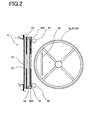
- Fig. 2 is a sectional view showing the main display 5 and the reel 3C.
- the main display 5 is constructed from a picture sheet 53 formed from the transparent film material on which various pictures are printed, the picture sheet 53 being arranged inside of an acrylic resin plate 52 functioning as a protect cover, a liquid crystal display device 54 formed from a transparent liquid crystal display device in which transparent electrodes are arranged and a light guiding plate 36.
- the picture sheet 53, the liquid crystal display device 54 and the light guiding plate 36 are stacked with each other.
- a touch panel 51 which detects coordinates corresponding to the contact area on which the player contacts.
- liquid crystal backlights 292, 293 as illumination of the liquid crystal display device 54 are arranged.
- the player By turning on the liquid crystal backlights 292, 293, the player can clearly seen and recognize the image displayed on the liquid crystal display device 54.
- symbol illumination lamps 57, 58 for illuminating the symbols on the reels 3L, 3C, 3R are arranged.
- the symbol illumination lamps 57, 58 are controlled so as to turn on when electric power is supplied, thereby the symbols on the reels 3L, 3C, 3R can be clearly seen and recognized.
- the symbol illumination lamps 57, 58 although cold cathode ray tubes are generally utilized, the present invention is not limited to this.
- the pictures described on the picture sheet 53 are always seen and recognized by the player, in spite of effect control state in the slot machine 1.
- the liquid crystal display device 54 constructs the effect area of image not only in the slot game mentioned later but also in the bonus game.
- a lamp housing 62 in which reel back lamps (not shown) turned on to easily see and recognize the symbols are installed.
- the sub-display 6 is constructed from a picture sheet 63, a liquid crystal display device 64 and a light guiding plate 67, which are stacked with each other at the inner side of a transparent acrylic resin plate 65. And at the upper side and the lower side of the liquid crystal display device 64, liquid crystal backlights 296, 297 are provided. Since the reels are not arranged behind the sub-display 6, symbol illumination lamps are not arranged.
- Fig. 4 it is shown symbol rows in each of which different kinds of symbols are arranged, the symbols being formed on the outer periphery of each reel 3L, 3C, 3R.
- the symbol row is constructed from plural kinds of symbols which are positioned at odd positions and plural blank symbols 92 positioned at even positions.
- a code number among 1 to 22 is attached and these code numbers are stored in a ROM 122 (see Fig. 9 mentioned later) as a data table.
- the "map 3" symbol 98 which includes a condor in a part of the map and completes one map picture with the "map 1" symbol 96 and the "map 2" symbol 97
- the "map 4" symbol 99 which includes a gate in a part of the map and completes one map picture with the "map 1" symbol 96 and the "map 2" symbol 97
- the map picture represents a treasure map and an item appearing in a treasure-hunting which is a theme of the slot machine 1.
- Fig. 5 shows a payout table displayed on the second display 6 when the slot game, which is the base game in the slot machine 1, is conducted.
- the payout table indicates how many coins are paid out corresponding to each of the winning combinations.
- tow states one of which is the slot game and the other of which is the bonus game as the secondary game.
- the reels 3L, 3C, 3R are started to rotate by depressing the maximum BST spin switch 18 or the repeat BET spin switch 19.
- the reels 3L, 3C, 3R are stopped in a predetermined order. At that time, if the symbol combination stopped along the pay line 8 corresponds to the predetermined symbol combination, that is, the winning combinations is won, coins are paid out to the player.
- the bonus game is a game which occurs when the specific symbol combination, for example, the combination of the "map 1" symbol 96, the “map 2" symbol 97 and the “map 3" symbol 98 ("map 1-map 2-map 3") is stopped along the pay line 8.
- the specific symbol combination for example, the combination of the "map 1" symbol 96, the “map 2" symbol 97 and the “map 3” symbol 98 ("map 1-map 2-map 3") is stopped along the pay line 8.
- the description "map 1-map 2-map 3" means a case that the "map 1" symbol, the "map 2" symbol and the “map 3" symbol are stopped along the pay line 8 which positions in the center of each of the display windows 4L, 4C, 4R.
- the payouts will be described according to Fig. 5 when the symbol combinations stopped along the pay line 8 become the predetermined combinations.
- the symbol combination stopped along the pay line 8 is determined based on the probability lottery table (mentioned later) by utilizing the random number sampled every the game.
- three "2BAR"s are line up along the pay line 8 when all reels 3L, 3C, 3R are stopped, twenty coins are paid out in a case that one coins is betted, forty coins are paid out in a case that two coins are betted and sixty coins are paid out in a case that three or four coins are betted. Thus, the payout is given to the player.
- the "WILD" symbol has substitutional function for each symbol of the "1BAR.” symbol, the "2BAR” symbol, the "3BAR” symbol and the "RED7” symbol, which are mentioned above.
- the "WILD” symbol substitutes for the “1BAR” and it concludes that the symbol combination "1BAR-1BAR-1BAR", that is, the winning combination "1BAR” is won.
- the probability lottery table is a table utilized when the symbols which line up along the pay line 8 are determined at the time that all reels 3L, 3C, 3R are stopped in the slot game.
- Fig. 6 shows the probability lottery table for the reels 3L, 3C, 3R to determine the symbols which line up along the pay line 8 when all reels 3L, 3C, 3R are stopped in a case that four coins are betted, that is, the bet number is four.
- the bet number is one ⁇ three although such tables are not shown.
- the concrete method to determine the symbol which line up along the pay line 8 by lottery is as follows.
- the CPU 21 (see Fig. 9) refers the random number value extracted from the predetermined random number range (for example, the range of 0 ⁇ 255) every each reel 3L, 3C, 3R with the probability lottery table shown in Fig. 6. Further, the CPU 21 judges that the extracted random number value lies in the random number range corresponding to which symbol and determines the symbol which line up along the pay line 8. For example, if the extracted random number value to determine the symbol on the left reel 3L lies in a range of 116 ⁇ 170, the symbol which line up along the pay line 8 when the left reel 3L is stopped becomes the "2BAR" symbol.
- the present invention is not limited to this.
- the winning combination corresponding to the symbol combination that is, the internal winning combination may be determined and the symbol which line up along the pay line 8 may be determined according to the internal winning combination. That is to say, the slot machine 1 may have internal winning combination determination means to determine the winning combination based on the random number value sampled every game.
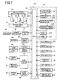
- Fig. 7 shows circuitry construction including a main control circuit 71 for controlling game process operation in the slot machine 1, periphery device (actuator) connected to the main control circuit 71 and a sub-control circuit 171 for controlling the main display 5 and the sub-display 6 based on control instruction transmitted from the main control circuit 71.
- the main control circuit 71 is mainly constructed from a microcomputer 120 arranged on a circuit board to which a circuit for sampling the random number.
- the microcomputer 120 includes the CPU 121 as a control device for conducting control operation according to a preset program and a ROM 122 and a RAM 123 which are memory means.
- a clock pulse generator 124 for generating standard clock pulses, a frequency divider 125, a random number generator 126 for generating random numbers sampled and a random number sampling circuit 127 are connected to the CPU 121.
- the means for sampling the random number random number generation and sampling thereof may be executed by calculation through the CPU 121 in the microcomputer 120.
- the random number generator 126 and the random number sampling circuit 127 can be omitted, or the random number generator 126 and the random number sampling circuit 127 may be remained so as to back up the random number sampling operation.
- a program for controlling game in the slot machine 1 a symbol table referred when the symbols lining up along the pay line 8 are determined in a case that all reels 3L, 3C, 3R are stopped, a winning symbol combination table referred after stop control of the reels 3L, 3C, 3R is done and thereafter the reels are stopped and a probability lottery table referred when the symbols lining up along the pay line 8 are determined in a case that all reels 3L, 3C, 3R are stopped, are stored.
- ROM 122 of the microcomputer 120 it is stored a simultaneous stop symbol selection lottery table which is utilized when more than two reels, variable display operation of which is controlled and stopped, are selected among the reels 3L, 3C, 3R by the lottery, so that more than two symbols constructing a symbol combination with a predetermined display mode are simultaneously stopped along the pay line 8, in a case that the symbol combination stopped along the pay line 8 becomes a predetermined display mode (for example, the "map 1-map 2-map 3) when all reels 3L, 3C, 3R are stopped.
- various control commands to send to the sub-control circuit 171 are stored in the ROM 122. These commands include "demonstration display command", “all reels stop command”, “bonus game start command” to start image display of the bonus game on the second display 6.
- a hopper 30 including a drive part to pay out and storing coins therein, the main display 5 and the sub-display 6, various lamps 60 (error lamp 23, symbol illumination lamp 57 and the like).
- a motor drive circuit 31 a motor drive circuit 31, a hopper drive circuit 32, a sub-control circuit 171, a lamp drive circuit 45, respectively.
- These drive circuits controls operation of each actuator by receiving control signals such as drive instructions output from the CPU 121.
- the sub-control circuit 171 conducts effect control of the main display 5 and the second display 6 based on the control command from the microcomputer 120.
- the sub-control circuit 171 will be described hereinafter.
- a power amplifier 42 functioning as an amplifier for amplifying sounds output from the speaker 43 is connected to the output terminal of the CPU 121 through a sound source IC 41.
- the sound source IC 41 controls the power amplifier 42 and the speaker 43 based on the control signal such as control command output from the CPU 121.
- a coin sensor 12S for detecting coins inserted in the coin insertion slot 12, an error switch 13, a help switch 14, a spin switch 15, a cash-out switch 16, a BET switch 17, a maximum BET spin switch 18, a repeat BET spin switch 19, a reel position detection circuit 34 supplying signals to detect positions of the reels 3L, 3C, 3R to the CPU 121 based on pulse signals output from a reel position detector (not shown) and a payout completion signal circuit 36 supplying a signal to detect coin payout completion to the CPU 121 in a case that the count number counted by a coin detection portion 35, which detects coins paid out from the hopper 30, reaches to the predetermined coin number data.
- the CPU 121 supplies the payout command signal to the hopper drive circuit 32, thereby the hopper 30 pays out the predetermined number of coins.
- the coin detection portion 35 counts the number of coins paid out from the hopper 30 and when the counted number of coins reaches to the predetermined number, the coin payout completion signal is input to the CPU 121. Thereby, the CPU 121 stops drive of the hopper 30 through the hopper drive circuit 32 and coin payout process is finished.
- the main control circuit 71, the hopper 30 and the hopper drive circuit 32 constructs award providing means for providing award to the player when the symbol combination determined by stop symbol determination means and stopped along the pay line 8 becomes the predetermined display mode.
- the random number generator 126 generates random numbers within a predetermined value range and the random number sampling circuit 127 samples the random number at a voluntarily timing after the spin switch 15, the maximum BET spin switch 18 and the repeat BET spin switch 19 are pressed.
- the sample random number is determined whether such random number belongs to which range in the probability lottery table stored in the storing part in the ROM 122. If the sampled random number belongs to a predetermined range, the stop symbol signal is generated, thereby control of the reels 3L, 3C, 3R mentioned later is conducted and the determined symbol is stopped along the pay line 8.
- the number of drive pulses supplied to each of the stepping motors 49L, 49C, 49R are counted, and the counted number value is written in a predetermined area in the RAM 123.
- a reset pulse is obtained from each of the reels 3L, 3C, 3R every one rotation thereof and such reset pulses are input to the CPU 121 through the reel position detection circuit 34.
- the CPU 121 clears the counted number of drive pulses stored in the RAM 123 to "0" based on the reset pulses obtained as mentioned. Thereby, in the RAM 123, the count number value corresponding to the rotational position of each of the reels 3L, 3C, 3R within one rotation thereof.
- the symbol table is stored in the ROM 122.
- this symbol table by utilizing the rotational position generated on the basis of the above mentioned reset pulse as the standard, code number serially given every a predetermined rotation pitch of each of the reels 3L, 3C, 3R and symbol code representing the symbol provided every each code number are corresponded with each other.
- the main control circuit 71 including the CPU 121, the ROM 122, the clock pulse generator 124, the frequency divider 125, the random number generator 126 and the random number sampling circuit 127, constructs stop symbol determination means for determining the symbol stopped along the pay line 8 every the variable display device based on the random number value sampled every game.
- main control circuit 71 including the CPU 121 and the ROM 122 constructs stop control means for stopping and controlling variable display operation of a plurality of the variable display devices based on a determination result by the stop symbol determination means.
- the winning symbol combination table is also stored.
- the winning symbol combination table the symbol combinations corresponding to the winning combinations, the coin payout number corresponding to the winning combinations and the winning judgement codes representing the winning combinations are corresponded.
- the winning symbol combination table is referred when variable display operation of the left reel 3L, the center reel 3C and the right reel 3R is controlled to stop and when the winning combination is confirmed after all reels are stopped.
- variable display operation of the reels 3L, 3C, 3R will be described.
- all reels 3L, 3C, 3R start to rotate based on a predetermined switch operation.
- Each of the reels 3L, 3C, 3R is stopped in a predetermined order after a predetermined time is elapsed.
- the slot machine 1 of the first embodiment in a case that the symbol combination stopped along the pay line 8 becomes a predetermined display mode shown in Fig.
- variable display operation of two reels among the reels 3L, 3C, 3R is controlled and stopped so that any two symbols constructing a symbol combination with a predetermined display mode are simultaneously stopped along the pay line 8. Thereafter, variable display operation of the remaining one reel is controlled and stopped.
- variable display operation of two reels among the reels 3L, 3C, 3R is controlled and stopped so that two symbols constructing a symbol combination with a predetermined display mode are simultaneously stopped along the pay line 8" includes a case that the player can feel that variable display of the two reels is stopped substantially at the same time when seeing the reels. Therefore, such sentence includes a case that one reel is first stopped and thereafter the other reel is stopped.
- Figs. 8 to 11 it will be described in detail a case that variable display operation of two reels is controlled and stopped so that any two symbols constructing a symbol combination with a predetermined display mode are simultaneously stopped along the pay line 8.
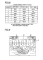
- Fig. 8 shows symbol combinations with a predetermined display mode in a case that variable display operation of two reels are controlled and stopped so that any two symbols constructing a symbol combination with a predetermined display mode are simultaneously stopped along the pay line 8.
- the symbol combination stopped at present time is determined as the symbol combination "map 1-map 2-any ("any” means the symbol except for the map 1 symbol, the map 2 symbol and WILD symbol).
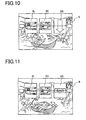
- all reels 3L, 3C, 3R start to rotate as shown in Fig. 9.
- the symbol combination stopped at present time corresponds to the predetermined display mode which is shown by No. 2 in Fig. 8. That is to say, the symbol to be stopped on the left reel 3L is the map 1 symbol, and the symbol to be stopped on the center reel 3C is the map 2 symbol. Therefore, as shown in Fig.
- variable display operation of the left reel 3L and variable display operation of the center reel 3C are controlled and stopped so that the map 1 symbol stopped along the pay line 8 when the left reel 3L is stopped and the map 2 symbol stopped along the pay line 8 when the center reel 3C is stopped are simultaneously stopped. And after a predetermined time is elapsed, variable display operation of the right reel 3R is controlled and stopped (see Fig. 11).
- variable display operation of the reels 3L, 3C, 3R is controlled and sopped so that the symbols constructing the reach mode (for example, the stopped symbol on the left reel 3L is the map 1 symbol and the stopped symbol on the center reel 3C is the map 2 symbol) are simultaneously stopped.
- the symbols constructing the reach mode for example, the stopped symbol on the left reel 3L is the map 1 symbol and the stopped symbol on the center reel 3C is the map 2 symbol
- variable display of all reel 3L 3C, 3R is controlled and stopped in the stop order different from the ordinary order according to which variable display operation of the reels 3L, 3C, 3R is serially stopped from the left reel, stop operation of the reels 3L, 3C, 3R can be changed, thereby interest of the player for games can be raised.
- the symbols constructing the symbol combination with a predetermined display mode are limited to the map 1 symbol, the map 2 symbol, the map 3 symbol and the WILD symbol, the present invention is not limited to this.
- the symbols constructing the symbol combination with a predetermined display mode may be the other symbols such as the RED 7 symbol, the 1BAR symbol, the 2BAR symbol or the 3BAR symbol.
- the main control circuit 71 constructing the stop control means has function to control and stop variable display operation of more than two variable display devices which variably display more than two symbols so that an more than two symbols constructing the symbol combination with a predetermined display mode are stopped along the pay line 8, in a case that the symbol combination stopped along the pay line 8 and determined by the stop symbol determination means becomes the predetermined display mode.
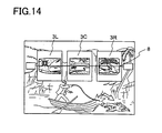
- the symbol combination stopped along the pay line 8 becomes the predetermined display mode (see Fig. 8), for example, the "map 1-map 2- map 3"
- any two symbols are selected among the map 1 symbol on the left reel 3L, the map 2 symbol on the center reel 3C and the map 3 symbol on the right reel 3R by the lottery.
- the simultaneous stop symbol selection lottery table shown in Fig. 12 is utilized when any two symbols are selected among the map 1 symbol, the map 2 symbol and the map 3 symbol.
- two reels variably displaying the selected two symbols are controlled and stopped so that the selected symbols are simultaneously stopped.
- "-" shown in the simultaneous stop symbol selection lottery table in Fig. 12 means that symbols are not selected.
- the CPU 121 extracts a random number within a predetermined range (for example, range of 0 ⁇ 255). And based on the extracted random number, the simultaneous stop symbol selection lottery table is referred shown in Fig. 12, and the symbol combination with the predetermined display mode is obtained. Thereafter, based on such symbol combination, it is selected that the symbol combination with the predetermined display mode belongs to which reel. For example, if the extracted random number lies in a range of 0 ⁇ 150, the selected two symbols correspond to the map 1 symbol on the left reel 3L and the map 3 symbol on the right reel 3R. Therefore, the left reel 3L and the right reel 3R are controlled and stopped so that the map 1 symbol on the left reel 3L and the map 3 symbol on the right reel 3R are simultaneously stopped.
- a predetermined range for example, range of 0 ⁇ 255.
- the symbol combination stopped along the pay line 8 becomes the predetermined display mode, more than two reels which are simultaneously stopped are changed according to the predetermined display mode. Therefore, by paying attention to the reel combination in which more than two symbols are simultaneously stopped, the player can concentrate for games and interest for games can be raised.
- variable display operation of the left reel 3L and the right reel 3R is controlled and stopped so that the map 1 symbol on the left reel 3L and the map 3 symbol on the right reel 3R are simultaneously stopped, and the symbol combination "map 1-map 2-map 3" becomes a chance to shift to the bonus game, expectation of the player for the bonus game can be expanded and also interest for games can be raised.
- the table in Fig. 12 shows the simultaneous stop symbol selection lottery table in which the symbol combination with the predetermined display mode is only the "map 1-map 2-map 3".
- the simultaneous stop symbol selection lottery table in which the symbols constructing the symbol combination with the predetermined display mode is the WILD symbol, its explanation will be omitted in the first embodiment.
- the reels 3L, 3C, 3R are stopped so that any two symbols always constructing the symbol combination with the predetermined display mode are simultaneously stopped along the pay line 8.
- the present invention is not limited to this. For example, even if the symbol combination stopped along the pay line 8 becomes the display mode shown in Fig.
- reels 3L, 3C, 3R are stopped, there may be a case that the reels 3L 3C, 3R are controlled and stopped so that two symbols, one of which constructs the symbol combination with the predetermined display mode and the other of which does not construct the symbol combination with the predetermined display mode, are simultaneously stopped along the pay line 8.
- the reels 3L, 3C, 3R are stopped so that any two symbols constructing the symbol combination with the predetermined display mode are simultaneously stopped along the pay line 8.
- the present invention is not limited to this. For example, even if the symbol combination stopped along the pay line 8 becomes the display mode shown in Fig.
- the main control circuit 71 constructs the simultaneous stop symbol selection lottery means to select any more than two symbols constructing the symbol combination with the predetermined display mode by the lottery according to the predetermined display mode, if the symbol combination stopped along the pay line and determined by the stop symbol determination means becomes the predetermined display mode.
- the sub-control circuit 171 is constructed from the sub-CPU 221, the sub-ROM 222, the sub-ram 223 and the image display control circuit 224, 225.
- the main control circuit 71 and the sub-control circuit 171 and between the sub-CPU 221 and each of the actuators, IN port and OUT port are voluntarily arranged.
- the sub-CPU 221 determines how to make the main display 5 and the sub-display 6 display based on a game information command transmitted from the main control circuit 71 and transmits data of display contents to the image display control circuits 224 and 225.
- a sequence program to utilized for transmission to the main control circuit 71, programs necessary for the slot game and the bonus game and various data are stored.
- the sub-ram 223 is utilized for work area when these programs are executed.
- the image display control circuit 224 has a video RAM (not shown) and controls display contents of the main display 5.
- the image display control circuit 225 has a video RAM (not shown) and controls display contents of the sub-display 6. In particular, the image display control circuit 225 controls the sub-display 6 so as to display the image of the bonus game based on a bonus game start command transmitted from the main control circuit 71.
- the main control circuit 71 constructs the secondary game start means to start the bonus game as the secondary game to give the specific award to the player, on condition that the symbol combination stopped along the predetermined pay line determined by the stop symbol determination means becomes the specific display mode.
- the bonus game is mainly conducted on the second display 6 when the symbol combination stopped along the pay line 8 when all reels 3L, 3C, 3R are stopped becomes the predetermined display mode (for example, in the first embodiment, the "map 1-map 2-map 3", see Fig. 14).
- the reels 3L, 3C, 3R are controlled and stopped so that two symbols constructing the "reach mode" (for example, the stopped symbol (map 1) on the left reel 3L and the stopped symbol (map 2) on the center reel 3C) are simultaneously stopped. Thereafter, variable display operation of the other remaining reel is controlled and stopped.
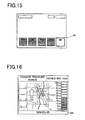
- the image to determine the BET number 301 for the bonus game is displayed on the main display 5, as shown in Fig, 15.
- the BET number 301 for the bonus game is determined.
- the image shown in Fig. 16 is displayed on the second display 6.
- the game in which a hero automatically climbs upward by using a rope is progressed. Every the hero climbs upward b using the rope a magnification indicated in a magnification meter 302 displayed at the right position becomes larger.
- the BET number for the bonus game becomes larger the probability with which the bonus game is terminated is controlled so as to become higher at the stage of low magnification.
- the bonus game is terminated. Thereafter, coins calculated by multiplying the BET number for the bonus game with the magnification are paid out to the player. For example, if the BET number for the bonus game is 50 as shown in Fig. 15 and the magnification is 20 as shown in Fig. 17, 1000 coins calculated by multiplying 50 with 20 are paid out to the player.
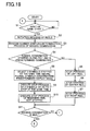
- the CPU 121 judges whether the game start input is done or not in step 1 (abbreviated as "S1" herein after). Concretely, the CPU 121 judges whether or not input process of the start signal from the spin switch 15, the maximum BET spin switch 18 or the repeat BET spin switch 19 is done.
- the CPU 121 executes rotation process of the reels 3L 3C, 3R (S2). Concretely, the CPU 121 sends a drive signal to the motor drive circuit 31 and rotates the reels 3L, 3C, 3R through the motor drive circuit 31. After this process is done, the CPU 121 shifts procedure to S3.
- the CPU 121 executes random number sampling process and winning combination judgement process (S3).
- the random number sampling process the CPU 121 generates a signal to generate random number against the random number generator 126 and makes the random number generator 126 extract random number every each of the reels 3L, 3C, 3R. And the CPU 121 stores the extracted random number value in the predetermined area of the RAM 123.
- the winning combination judgement process the CPU 121 judges every each of the reels 3L, 3C, 3R that the random number value stored in the RAM 123 belongs to which range in the probability lottery table stored in the ROM 122, thereby the CPU 121 determines the symbols stopped along the pay line 8 and stores the symbols in the RAM 123.
- the CPU 121 judges that the determined symbols corresponds to which winning combination in the winning symbol combination table stored beforehand in the ROM 122.
- the CPU 121 judges whether or not the symbol combination stopped along the pay line 8 is the predetermined display mode shown in Fig. 8 (S4).
- process of S4 it is judged that the symbol combination stopped along the pay line 8 is not the predetermined display mode (for example, the symbol combination "WILD-RED7-RED7" which is not shown in Fig. 8), the CPU 121 conducts stop process of the left reel 3L S5).
- the CPU 121 sends to the motor drive circuit 31 a signal to control and stop variable display operation of the left reel 3L corresponding to the stop symbols determined in process of S3, and the motor drive circuit 31 stops the left reel 3L through the stepping motor 49L after a predetermined time is elapsed.
- the CPU 121 shifts procedure to S6.
- the CPU 121 conducts stop process of the center reel 3C (S6).
- the CPU 121 sends to the motor drive circuit 31 a signal to control and stop variable display operation of the center reel 3C corresponding to the stop symbols determined in process of S3, and the motor drive circuit 31 stops the center reel 3C through the stepping motor 49C after a predetermined time is elapsed.
- the CPU 121 shifts procedure to S7.
- the CPU 121 conducts stop process of the right reel 3R (S7).
- the CPU 121 sends to the motor drive circuit 31 a signal to control and stop variable display operation of the right reel 3R corresponding to the stop symbols determined in process of S3, and the motor drive circuit 31 stops the right reel 3R through the stepping motor 49R after a predetermined time is elapsed.
- the CPU 121 shifts procedure to S11.
- the CPU 121 selects two symbols simultaneously stopped among a plurality of symbols constructing the predetermined display mode by the lottery (S8). For example, in this process, the CPU 121 selects two symbols simultaneously stopped by referring the extracted random number value with the simultaneous stop symbol selection lottery table shown in Fig. 12. Concretely, the CPU 121 extracts the random number from a predetermined random number range (for example, range of 0 ⁇ 255).
- the predetermined display mode is the "map 1- map 2-map 3" and the extracted random number value lies in a range of 151 ⁇ 200, the selected two symbols become the "map 2" on the center reel 3C and the "map 3" on the right reel 3R (see Fig. 12).
- the CPU 121 shifts procedure to S9.
- the CPU 121 conducts stop process of two reels so that the selected two reels are simultaneously stopped (S9).
- the CPU 121 controls and stops variable display operation of two reels variably displaying two symbols so that two symbols selected in S8 are simultaneously stopped. For example, if two symbols selected in S8 are the "map 2" on the center reel 3C and the "map 3" on the right reel 3R, the CPU 121 sends to the motor drive circuit 31 a signal to control and stop variable display operation of the center reel 3C and the right reel 3R and controls and stops the center reel 3C and the right reel 3R so that the "map 2" on the center reel 3C and the "map 3" on the right reel 3R are simultaneously stopped through the stepping motors 49C and 49R. After this process is done, the CPU 121 shifts procedure to S10.
- the CPU 121 conducts stop process of the remaining reel not stopped yet (S10).
- the CPU 121 controls and stops variable display operation of the reel different from two reels controlled and stopped in S9. For example, in S9, if the center reel 3C and the right reel 3R are stopped so that the "map 2" on the center reel 3C and the "map 3" on the right reel 3R are simultaneously stopped, the remaining reel 3L which is rotating is stopped. After this process is done, the CPU 121 shifts procedure to S 11.
- variable display operation of the reels 3L, 3C, 3R is controlled and stopped so that the symbols constructing the "reach mode" are simultaneously stopped. Therefore, it can be given to the player expectation that game condition may shift to the bonus game or coins may be paid out by the winning combination. As a result, interest of the player for games can be raised.
- variable display of all reel 3L 3C, 3R is controlled and stopped in the stop order different from the ordinary order according to which variable display operation of the reels 3L, 3C, 3R is serially stopped from the left reel, stop operation of the reels 3L, 3C, 3R can be changed, thereby interest of the player for games can be raised.
- the CPU 121 judges whether or not the winning combination is won at present time based on the result in the winning combination judgement process in S3.
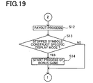
- the CPU 121 In S11, if it is judged that the winning combination is won at present time, the CPU 121, as shown in Fig. 19, the CPU 121 conducts payout process of coins (S12). In this process, the CPU 121 sends to the hopper drive circuit 32 a coin payout signal corresponding to the kind of the winning combination, thereby a predetermined number of coins are paid out from the hopper 30. At that time, the coin detection part 35 counts number of coins paid out from the hopper 30 and the payout completion signal circuit 36 outputs the payout completion signal to the CPU 121 at the time that the counted value reaches to the predetermined coin number data. Thereby, the CPU 121 stops drive of the hopper 30 through the hopper drive circuit 32 and coin payout process is terminated.
- the CPU 121 judges whether or not the symbol combination stopped along the pay line 8 is the predetermined display mode (S13). Concretely, the CPU 121 judges whether or not the symbol combination stopped along the pay line 8 is the symbol combination "map 1- map 2- map 3" which gives a chance to shift the slot game to the bonus game.
- the CPU 121 executes bonus game start process (S15). In this process, the CPU 121 sends the bonus game start command to the sub-control circuit 171. In the sub-control circuit 171 to which the bonus start command is sent, the image of the bonus game is displayed on the second display 6. After this process is done, the CPU 121 returns procedure to S1.
- the probability with which the bonus game giving the specific award to the player is started becomes high. That is to say, since the reels 3L, 3C, 3R are stopped in the stop order different from the ordinary stoop order, it can be recognized by the player that the probability with which the bonus game is started becomes high. Therefore, expectation of the player for games can be highly raised.
- the slot machine according to the second embodiment of the present invention will be described.
- the slot machine of the second embodiment has substantially the same construction as that of the slot machine of the first embodiment already mentioned in the above. Therefore, the second embodiment will be described hereinafter by only taking the characteristic construction of the second embodiment into consideration.
- members as in the slot machine of the first embodiment the same numbers, marks and the like are added.
- a stop order selection lottery table which is utilized when a stop order of the reels 3L, 3C, 3R is selected by the lottery, the stop order being different from an ordinary order according to which, for example, the reels are stopped in the order of the left reel 3L, the center reel 3C and the right reel 3R, in a case that the symbol combination stopped along the pay line 8 becomes a predetermined display mode (for example, the "map 1-map 2-map 3) when all reels 3L, 3C, 3R are stopped.
- variable display operation of the reels 3L, 3C, 3R is controlled and stopped so that the reels 3L, 3C, 3R are stopped in the stop order, for example, in the stop order of the left reel 3L, the right reel 3R and the center reel 3C, differently from the ordinary stop order according to which, for example, the left reel 3L, the center reel 3C and the right reel 3R are stopped in this order.
- Fig. 8 shows symbol combinations with a predetermined display mode in a case that variable display operation of two reels are controlled and stopped so that any two symbols constructing a symbol combination with a predetermined display mode are stopped along the pay line 8.
- the symbol combination stopped at present time is determined as the symbol combination "map 1-map 2-any ("any” means the symbol except for the map 1 symbol, the map 2 symbol and WILD symbol).
- all reels 3L, 3C, 3R start to rotate as shown in Fig. 9.
- the symbol combination stopped at present time corresponds to the predetermined display mode which is shown by No. 2 in Fig. 8. That is to say, the symbol to be stopped on the left reel 3L is the map 1 symbol, and the symbol to be stopped on the center reel 3C is the map 2 symbol.
- the ordinary stop order as shown in Fig.
- variable display operation of the left reel 3L is first controlled and stopped, thereafter variable display operation of the center reel 3C and the right reel 3R is controlled and stopped in this stop order.
- the reels 3L, 3C and 3R are stopped according to this stop order.
- variable display operation of the reels 3L, 3C, 3R is controlled and stopped (see Fig. 22) so that, for example shown in Fig. 21, the left reel 3L is first stopped, thereafter variable display operation of the right reel 3R is controlled and stopped and finally variable display operation of the center reel 3C is controlled and stopped, according to the stop order different from the ordinary stop order.
- the main control circuit 71 constructing the stop control means has function to control and stop variable display operation of plural variable display devices according to the stop order different from the ordinary stop order, in a case that the symbol combination stopped along the pay line 8 and determined by the stop symbol determination means becomes the predetermined display mode.
- the CPU 121 extracts a random number within a predetermined range (for example, range of 0 ⁇ 255). And based on the symbol combination of the predetermined display mode and the extracted random number, the stop order of the reels 3L, 3C, 3R is determined with reference to the stop order selection table shown in Fig. 23. For example, if the extracted random number lies in a range of 151 ⁇ 175 and the symbol combination to be stopped along the pay line 8 is the "map 1-map 2-map 3" when all reels 3L, 3C, 3R are stopped, variable display operation of the reels 3L, 3C, 3R is controlled and stopped according to the stop order of the center reel 3C, the right reel 3R and the left reel 3L.
- a predetermined range for example, range of 0 ⁇ 255.
- the stop order of the reels 3L, 3C, 3R is selected by the lottery. Therefore, since the stop order of the reels 3L, 3C, 3R is made different every one game, the player becomes to pay attention to the stop order of the reels 3L, 3C, 3R. Thus, the player can concentrate for games and interest for games can be raised.
- variable display operation of the reels 3L, 3C, 3R is controlled and stopped according to the stop order of the left reel 3L, the right reel 3R and the center reel 3C with higher probability than a case that variable display operation of the reels 3L, 3C, 3R is controlled and stopped according to the other stop order. Therefore, if the stop order of the reels 3L, 3C, 3R is the stop order of the left reel 3L, the right reel 3R and the center reel 3C, the symbol combination stopped along the pay line 8 becomes the "map 1-map 2-map 3" with relatively probability.
- variable display operation is controlled and stopped according to the stop order of the left reel 3L and the right reel 3R, and the symbol combination "map 1-map 2-map 3" becomes a chance to shift to the bonus game, expectation of the player for the bonus game can be expanded and also interest for games can be raised.
- the table in Fig. 23 shows the stop order selection lottery table in which the symbol combination with the predetermined display mode is only the "map 1-map 2-map 3".
- the stop order selection lottery table in which the symbols constructing the symbol combination with the predetermined display mode is the WILD symbol, its explanation will be omitted in the second embodiment.
- the left reel 3L, the center reel 3C and the right reel 3R are stopped according to the stop order different from the ordinary order.
- the present invention is not limited to this. For example, even if the symbol combination stopped along the pay line 8 becomes the display mode shown in Fig. 8 when all reels 3L, 3C, 3R are stopped, there may be a case that the reels are stopped according to the ordinary stop order of the left reel 3L, the center reel 3C and the right reel 3R.
- variable display operation of the reels 3L, 3C, 3R is controlled and stopped according to the stop order so that the "reach mode" is always realized.
- the present invention is not limited to this.
- variable display operation of the reels 3L, 3C, 3R is controlled and stopped according to the stop order that the "reach mode" is not realized.
- the main control circuit 71 constructs the stop order storing means for storing a plurality of stop orders of plural variable display devices.
- the main control circuit 71 constructs the stop order selection lottery means for selecting one stop order of plural variable display devices among a plurality of stop orders of plural variable display devices stored in the stop order storing means by the lottery corresponding to the predetermined display mode, in a case that the symbol combination stopped along the pay line and determined by the stop symbol determination means becomes the predetermined display mode.
- the bonus game is conducted in the slot game 1 of the second embodiment, if the symbol combination stopped along the pay line 8 when all reels 3L, 3C, 3R are stopped becomes the predetermined display mode, for example, the symbol combination "map 1-map 2- map 3" (see Fig. 14) in the second embodiment, as mentioned, variable display operation of the reels 3L, 3C, 3R is controlled and stopped according to the stop order different from the ordinary stop order.
- the symbol combination stopped along the pay line 8 when all reels 3L, 3C, 3R are stopped becomes the predetermined display mode, for example, the symbol combination "map 1-map 2- map 3" (see Fig. 14) in the second embodiment, as mentioned, variable display operation of the reels 3L, 3C, 3R is controlled and stopped according to the stop order different from the ordinary stop order.
- variable display operation of the reels 3L, 3C, 3R is controlled and stopped according to the estop order different from the ordinary order, probability with which the bonus game giving the specific award to the player is started becomes high (see Fig. 23). That is to say, since the reels 3L, 3C, 3R are controlled and stopped according to the stop order different from the ordinary order, it can be recognized by the player that the probability with which the bonus game is started becomes high. Therefore, expectation of the player for games can be highly raised.
- control operation by the CPU 121 in the main control circuit 71 of the second embodiment will be described.
- control operation by the CPU 121 is almost same as that in the first embodiment. That is to say, in Fig. 24, processes in S28 and S29 are provided instead of the processes in S8 to S10 in Fig. 18. The other processes are same in both Figs. 24 and 18.
- control operation by the CPU 121 in the second embodiment is conducted according to the flowchart shown in Fig. 19 after processes in Fig. 24 are done. Therefore, only processes in S28 and 29 shown in Fig. 24, such processes being characteristic to the second embodiment, will be described hereinafter.
- the CPU 121 selects the stop order of the reels by the lottery (S28). In this process, the CPU 121 selects one stop order among a plurality of stop orders of the reels 3L, 3C, 3R by the lottery with reference to the stop order selection lottery table shown in Fig. 23, based on the extracted random number value and the symbol combination determined in S23 (the symbol combination with the predetermined display order). Concretely, the CPU 121 extracts the random number from a predetermined random number range (for example, range of 0 ⁇ 255).
- the variable display operation of the reels 3L, 3C, 3R is controlled and stopped according to the stop order of the center reel 3C, the left reel 3L and the right reel 3R (see Fig. 23). After this process is done, the CPU 121 shifts procedure to S29.
- the stop order of the reels 3L, 3C, 3R is selected by the lottery. Therefore, since the stop order of the reels 3L, 3C, 3R is differently changed, the player pays attention to the stop order of the reels 3L, 3C, 3R, thereby the player can concentrate for the game and interest for games can be raised.
- the CPU 121 conducts stop process of the reels according to the stop order selected by the lottery (S29).
- the CPU 121 controls and stops variable display operation of the reels 3L, 3C, 3R according to the stop order selected in S 28.
- the CPU 121 first sends to the motor drive circuit 31 a signal to control and stop the center reel 3C and stops the center reel 3C through the stepping motor 49C.
- the CPU 121 sends to the motor drive circuit 31 a signal to control and stop the left reel 3L after a predetermined time is elapsed and stops the left reel 3L through the stepping motor 49L. Further, the CPU 121 sends to the motor drive circuit 31 a signal to control and stop the right reel 3R after a predetermined time is elapsed and stops the right reel 3R through the stepping motor 49R. After this process is terminated, the CPU 121 shifts procedure to S 30.
- variable display operation of the reels 3L, 3C, 3R is controlled and stopped according to the stop order different from the ordinary stop order. That is to say, if the symbol combination with the predetermined display mode becomes the "reach mode" such as the "map 1-map 2-any", variable display operation of the reels 3L, 3C, 3R is controlled and stopped according to the stop order, for example, the stop order of the center reel 3C, the left reel 3L and the right reel 3R, different from the ordinary stop order, for example the stop order of the left reel 3L, the center reel 3C and the right reel 3R (that is, the reels are stopped from the left reel to the right reel).
- the stop order for example, the stop order of the center reel 3C, the left reel 3L and the right reel 3R, different from the ordinary stop order, for example the stop order of the left reel 3L, the center reel 3C and the right reel 3R (that is, the reels are stopped from the left reel to the right reel).
- variable display operation of the reels 3L, 3C, 3R is controlled and stopped according to the stop order different from the ordinary stop order in only a case that the symbol combination becomes the predetermined display mode, it can be given expectation to the player.
- variable display operation of the reels 3L, 3C, 3R is controlled and stopped according to the stop order different from the ordinary stop order, the probability with which the bonus game giving the specific award to the player is started becomes high. That is to say, since the reels 3L, 3C, 3R are stopped according to the stop order different form the ordinary stop order, it can be recognized by the player that the probability with which the bonus game is started becomes high. Therefore, expectation of the player for games can be highly raised.
- the slot machine according to the third embodiment of the present invention will be described.
- the slot machine of the third embodiment has substantially the same construction as that of the slot machine of the first embodiment already mentioned in the above. Therefore, the third embodiment will be described hereinafter by only taking the characteristic construction of the third embodiment into consideration.
- members as in the slot machine of the first embodiment the same numbers, marks and the like are added.
- the spin switch 15 is a switch to start rotation of the reels 3L, 3C, 3R and has function to control and stop variable display operation of any one reel among the reels 3L, 3C, 3R by player's operation, as mentioned later.
- the spin switch 15 functions as the switch to control and stop variable display operation of any one of the reels 3L, 3C, 3R
- the spin switch 15 may be the switch to control and stop variable display operation of more than one reel among a plurality of reels.
- variable display operation of two reels is controlled and stopped so that more than any two reels constructing the symbol combination with the predetermined display mode are simultaneously stopped along the pay line 8, and thereafter when the spin switch 15 is operated by the player, variable display operation of any one reel among the reels 3L, 3C, 3R is controlled and stopped.
- the stop symbols are not determined by operation of the player and stop control of variable display operation of the reels is only started by utilizing the player's operation as the trigger.
- the stop start signal occurs from the spin switch 15 and such stop start signal is supplied to the CPU 121. Further, the stop start signal is supplied to the motor drive circuit 31 from the CPU 121. Thereby, stop control of variable display operation of the reels 3L, 3C, 3R is started.
- variable display operation of the reels 3L, 3C, 3R will be described.
- all reels 3L, 3C, 3R start to rotate based on a predetermined switch operation.
- Each of the reels 3L, 3C, 3R is stopped in a predetermined order after a predetermined time is elapsed.
- the slot machine 1 of the third embodiment in a case that the symbol combination stopped along the pay line 8 becomes a predetermined display mode shown in Fig.
- variable display operation of two reels among the reels 3L, 3C, 3R is controlled and stopped so that any two symbols constructing a symbol combination with a predetermined display mode are simultaneously stopped along the pay line 8. Thereafter, variable display operation of the remaining one reel is controlled and stopped. And variable display operation of the remaining one reel is controlled and stopped by the player's operation of the spin switch 15.
- variable display operation of the remaining one reel is controlled and stopped by the player's operation of the spin switch 15
- stop symbol is not determined by the player's operation of the spin switch 15 and stop control of variable display operation of the reel is only started by utilizing the player's operation as the trigger.
- sentence includes a case that the player feels as if variable display operation of the remaining reel is controlled and stopped by the player's operation when seeing the reels.
- the main control circuit 71 constructs the stop control means for controlling and stopping variable display operation of a plurality of variable display devices based on the result determined by the stop symbol determination means by utilizing the player's operation as the trigger.
- variable display operation of two reels is controlled and stopped so that any two symbols constructing a symbol combination with a predetermined display mode are simultaneously stopped along the pay line 8, thereafter variable display operation of any one reel of the reels 3L, 3C, 3R can be controlled and stopped by the player's operation.
- Fig. 8 shows symbol combinations with a predetermined display mode in a case that variable display operation of two reels are controlled and stopped so that any two symbols constructing a symbol combination with a predetermined display mode are simultaneously stopped along the pay line 8, thereafter variable display operation of any one reel of the reels 3L, 3C, 3R can be controlled and stopped by the player's operation.
- the symbol combination stopped at present time is determined as the symbol combination "map 1-map 2-any ("any” means the symbol except for the map 1 symbol, the map 2 symbol and WILD symbol).
- all reels 3L, 3C, 3R start to rotate as shown in Fig. 9.
- the symbol combination stopped at present time corresponds to the predetermined display mode which is shown by No. 2 in Fig. 8. That is to say, the symbol to be stopped on the left reel 3L is the map 1 symbol, and the symbol to be stopped on the center reel 3C is the map 2 symbol. Therefore, as shown in Fig.
- variable display operation of the left reel 3L and variable display operation of the center reel 3C are controlled and stopped so that the map 1 symbol stopped along the pay line 8 when the left reel 3L is stopped and the map 2 symbol stopped along the pay line 8 when the center reel 3C is stopped are simultaneously stopped.
- variable display operation of the right reel 3R is controlled and stopped (see Fig. 26).
- the message "Push the Reel Stop Button!” is displayed on the display area 5a of the main display 5.
- variable display operation of the center reel 3C is controlled and stopped by the player's operation of the spin switch 15. As a result, the "BAR" symbol is stopped (see Fig. 26).
- any one of reels 3L, 3C, 3R can be controlled and stopped by the player's operation. Therefore, according to the third embodiment, the player can technically intervene in the game and it can be given to the player a feeling that the player really participates in the game. Thereby, interest of the player for games can be raised. And since unexpected stop control is conducted comparing with a case that the reels 3L, 3C, 3R are automatically controlled and stopped, it can make the player pay attention to variable display operation of the reels 3L, 3C, 3R. As a result, interest of the player for games can be highly raised. Further, since variable display operation of one reel can be controlled and stopped by the player's operation only in a case that the symbol combination becomes the predetermined display mode, expectation can be given to the player.
- the symbol combination stopped along the pay line 8 becomes the predetermined display mode (see Fig. 8), for example, the "map 1-map 2- map 3"
- any two symbols are selected among the map 1 symbol on the left reel 3L, the map 2 symbol on the center reel 3C and the map 3 symbol on the right reel 3R by the lottery.
- the simultaneous stop symbol selection lottery table shown in Fig. 12 is utilized when any two symbols are selected among the map 1 symbol, the map 2 symbol and the map 3 symbol.
- two reels variably displaying the selected two symbols are controlled and stopped so that the selected symbols are simultaneously stopped.
- variable display operation of two reels is controlled and stopped
- variable display operation of any one reel among the reels 3L, 3C, 3R can be controlled and stopped by the player's operation.
- the simultaneous stop symbol selection lottery table shown in Fig. 12 is a table referred when the any one reel, which can be controlled and stopped by the player's operation, is selected among the reels 3L, 3C, 3R by the lottery, in a case that the symbol combination stopped along the pay line 8 becomes the predetermined display mode.
- “ - " shown in the simultaneous stop symbol selection lottery table in Fig. 12 means that symbols are not selected.
- the CPU 121 extracts a random number within a predetermined range (for example, range of 0 ⁇ 255). And based on the extracted random number, the simultaneous stop symbol selection lottery table is referred shown in Fig. 12, and the symbol combination with the predetermined display mode is obtained. Thereafter, based on such symbol combination, it is selected that the symbol combination with the predetermined display mode belongs to which reel. For example, if the extracted random number lies in a range of 0 ⁇ 150, the selected two symbols correspond to the map 1 symbol on the left reel 3L and the map 3 symbol on the right reel 3R. Therefore, the left reel 3L and the right reel 3R are controlled and stopped so that the map 1 symbol on the left reel 3L and the map 3 symbol on the right reel 3R are simultaneously stopped. And variable display operation of the center reel 3C is controlled and stopped by the player's operation of the spin switch 15.
- a predetermined range for example, range of 0 ⁇ 255.
- any one reel which can be controlled and stopped by the player's operation of the spin switch 15, is selected among the reels 3L, 3C, 3R by the lottery. Therefore, based on variable display operation of any one reel which can be controlled and stopped by the player's operation, there is a case that the symbol combination stopped along the pay line 8 can be predicted. Thus, the player pays attention to variable display operation of such reel. As a result, the player can concentrate for the game and interest for games can be raised.
- variable display operation of the left reel 3L and the right reel 3R is controlled and stopped so that the map 1 symbol on the left reel 3L and the map 3 symbol on the right reel 3R are simultaneously stopped, that is, variable display operation of the center reel 3C can be controlled and stopped by the player's operation, and the symbol combination "map 1-map 2-map 3" becomes a chance to shift to the bonus game, expectation of the player for the bonus game can be expanded and also interest for games can be raised.
- the table in Fig. 12 shows the simultaneous stop symbol selection lottery table in which the symbol combination with the predetermined display mode is only the "map 1-map 2-map 3".
- the simultaneous stop symbol selection lottery table in which the symbols constructing the symbol combination with the predetermined display mode is the WILD symbol, its explanation will be omitted in the first embodiment.
- the reels 3L, 3C, 3R are stopped so that any two symbols always constructing the symbol combination with the predetermined display mode are simultaneously stopped along the pay line 8.
- the present invention is not limited to this. For example, even if the symbol combination stopped along the pay line 8 becomes the display mode shown in Fig.
- variable display device selection lottery means for selecting more than one variable display device, which can be controlled and stopped by the player's operation of the stop operation portion, among a plurality of variable display devices by the lottery according to the predetermined display mode, if the symbol combination stopped along the pay line and determined by the stop symbol determination means becomes the predetermined display mode.
- the bonus game is mainly conducted on the second display 6 when the symbol combination stopped along the pay line 8 when all reels 3L, 3C, 3R are stopped becomes the predetermined display mode (for example, in the first embodiment, the "map 1-map 2-map 3", see Fig. 14).
- the reels 3L, 3C, 3R are controlled and stopped so that two symbols constructing the "reach mode" (for example, the stopped symbol (map 1) on the left reel 3L and the stopped symbol (map 2) on the center reel 3C) are simultaneously stopped. Thereafter, variable display operation of the other remaining reel is controlled and stopped by utilizing the player's operation as the trigger.
- the image to determine the BET number 301 for the bonus game is displayed on the main display 5, as shown in Fig, 15.
- the BET number 301 for the bonus game is determined.
- the image shown in Fig. 16 is displayed on the second display 6.
- the game in which a hero automatically climbs upward by using a rope is progressed. Every the hero climbs upward b using the rope a magnification indicated in a magnification meter 302 displayed at the right position becomes larger.
- the BET number for the bonus game becomes larger the probability with which the bonus game is terminated is controlled so as to become higher at the stage of low magnification.
- the bonus game is terminated. Thereafter, coins calculated by multiplying the BET number for the bonus game with the magnification are paid out to the player. For example, if the BET number for the bonus game is 50 as shown in Fig. 15 and the magnification is 20 as shown in Fig. 17, 1000 coins calculated by multiplying 50 with 20 are paid out to the player.
- variable display operation of one reel can be controlled and stopped by the player's operation of the spin switch 15, probability with which the bonus game giving the specific award to the player is started becomes high. That is to say, since variable display operation of one reel in the variable display device can be controlled and stopped by the player's operation, it can be recognized by the player that the probability with which the secondary game is started becomes high. Therefore, expectation of the player for games can be highly raised.
- control operation by the CPU 121 in the main control circuit 71 of the third embodiment will be described.
- control operation by the CPU 121 is almost same as that in the first embodiment. That is to say, in Fig. 27, judgement process in S40 is inserted between the process in S9 and the process in S10 in the flowchart shown in Fig. 18. The other processes are same in both Figs. 27 and 18. Further, control operation by the CPU 121 in the third embodiment is conducted according to the flowchart shown in Fig. 19 after processes in Fig. 27 are done. Therefore, only process in S40 shown in Fig. 27, such process being characteristic to the third embodiment, will be described hereinafter.
- the CPU 121 selects two symbols simultaneously stopped among a plurality of symbols constructing the predetermined display mode by the lottery (S8). For example, in this process, the CPU 121 selects two symbols simultaneously stopped by referring the extracted random number value with the simultaneous stop symbol selection lottery table shown in Fig. 12. Concretely, the CPU 121 extracts the random number from a predetermined random number range (for example, range of 0 ⁇ 255).
- the predetermined display mode is the "map 1- map 2-map 3" and the extracted random number value lies in a range of 151 ⁇ 200
- the selected two symbols become the "map 2" on the center reel 3C and the "map 3" on the right reel 3R (see Fig. 12). That is, it concludes that the left reel 3L is selected as the reel which can be controlled and stopped by the player's operation.
- the CPU 121 shifts procedure to S9.
- any one reel which can be controlled and stopped by the player's operation of the spin switch 15 is selected among the reels 3L, 3C, 3R by the lottery. Therefore, based on variable display operation of any one reel which can be controlled and stopped by the player's operation, there is a case that the symbol combination stopped along the pay line 8 can be predicted. Thus, the player pays attention to variable display operation of such reel. As a result, the player can concentrate for the game and interest for games can be raised.
- the CPU 121 judges whether stop operation is conducted or not (S40). In this step, the CPU 121 judges whether or not the spin switch 15 is pressed by the player.
- stop process of the remaining reel not stopped yet is executed (S41).
- the CPU 121 controls and stops variable display operation of the reel other than two reels variable display operation of which are controlled and stopped in S39, according to the operation in S40 by the player. For example, in S39, if the reel 3C and the reel 3R are stopped so that the "map 2" on the center reel 3C and the "map 3" on the right reel 3R are simultaneously stopped, the CPU 121 stops the left reel 3L which is rotating by utilizing the operation of the spin switch 15 by the player as the trigger. After this process is terminated, the CPU 121 shifts procedure to S42.
- any one of reels 3L, 3C, 3R can be controlled and stopped by the player's operation. Therefore, according to the third embodiment, the player can technically intervene in the game and it can be given to the player a feeling that the player really participates in the game. Thereby, interest of the player for games can be raised. And since unexpected stop control is conducted comparing with a case that the reels 3L, 3C, 3R are automatically controlled and stopped, it can make the player pay attention to variable display operation of the reels 3L, 3C, 3R. As a result, interest of the player for games can be highly raised. Further, since variable display operation of one reel can be controlled and stopped by the player's operation only in a case that the symbol combination becomes the predetermined display mode, expectation can be given to the player.
- variable display operation of one reel can be controlled and stopped by the player's operation of the spin switch 15, probability with which the bonus game giving the specific award to the player is started becomes high. That is to say, since variable display operation of one reel in the variable display device can be controlled and stopped by the player's operation, it can be recognized by the player that the probability with which the secondary game is started becomes high. Therefore, expectation of the player for games can be highly raised.
- variable display devices are not limited to this.
- two reels may be provided or more than four reels may be provided.
- the variable display devices are constructed from the reels, the present invention is not limited to this.
- the liquid crystal display device as the variable display device may be provided.
- variable display operation of any one reel among the reels 3L, 3C, 3R can be controlled and stopped
- the present invention is not limited to this.
- variable display operation of the reel which is first stopped or the reel which is second stopped may be controlled and stopped.
- stop operation part for controlling and stopping variable display operation of any one reel among the reels 3L, 3C, 3R corresponds to the spin switch 15
- the present invention is not limited to this.
- stop operation part which can control and stop variable display operation of any one reel among the reels 3L, 3C, 3R, may be constructed from the other switch such as the error switch 13 or the touch panel 51 provided on the main display 5 or the second display 6.
Landscapes
- Physics & Mathematics (AREA)
- General Physics & Mathematics (AREA)
- Slot Machines And Peripheral Devices (AREA)
Abstract
Description
Claims (9)
- A gaming machine comprising:wherein the stop control device has function to conduct the stop control of the variable display operation of more than two variable display devices variably displaying more than two symbols so that any more than two symbols are simultaneously stopped along the predetermined line, two symbols constructing a predetermined symbol combination with a specific display mode, in a case that the symbols determined by the stop symbol determination device constructs the predetermined symbol combination with the specific display mode.a plurality of variable display devices for variably displaying a plural kinds of symbols;a stop symbol determination device for determining the symbol stopped along a predetermined line every the variable display device based on a random number value sampled every game; anda stop control device for conducting stop control of variable display operation of the variable displaying devices based on a determination result determined by the stop symbol determination device;
- Th gaming machine according to claim 1, further comprising:wherein the stop control device has function to conduct the stop control of the variable display operation of more than two variable display devices variably displaying more than two symbols selected by the simultaneous stop symbol selection lottery device so that more than tow symbols selected by the simultaneous stop symbol selection lottery device are simultaneously stopped along the predetermined line.a simultaneous stop symbol selection lottery device for selecting any more than two symbols constructing the predetermined symbol combination with the specific display mode corresponding to the specific display mode by a lottery in a case that the predetermined symbol combination stopped along the predetermined line and determined by the stop symbol determination device becomes the specific display mode;
- The gaming machine according to claim 1, further comprising:wherein a probability that the secondary game is started by the secondary game start device is set high in a case that the variable display operation of more than two variable display devices variably displaying more than two symbols is controlled and stopped so that any two symbols constructing the predetermined symbol combination with the specific display mode are simultaneously stopped along the predetermined line.a secondary game start device for starting a secondary game giving a predetermined award to a player on a condition that the symbol combination stopped along the predetermined line and determined by the stop symbol determination device becomes the specific display mode;
- A gaming machine comprising:wherein the stop control device has function to conduct the stop control of the variable display operation of the variable display devices according to a stop order different from an ordinary stop order in a case that a symbol combination stopped along the predetermined line and determined by the stop symbol determination device becomes a specific display mode.a plurality of variable display devices for variably displaying plural kinds of symbols;a stop symbol determination device for determining the symbol stopped along a predetermined line every variable display device based on a random number value sampled every game; anda stop control device for conducting stop control of variable display operation of the variable display devices based on a determination result determined by the stop symbol determination device;
- The gaming machine according to claim 4, further comprising:a stop order storing device for storing a plurality of stop orders of the variable display devices; anda stop order selection lottery device for selecting one stop order of the variable display devices among the stop orders stored in the stop order storing device by a lottery in a case that the symbol combination becomes the specific display mode.
- The gaming machine according to claim 4, further comprising:wherein a probability that the secondary game is started by the secondary game start device is set high in a case that the variable display operation of the variable display devices is controlled and stopped according the stop order different from the ordinary stop order.a secondary game start device for starting a secondary game giving a predetermined award to a player on a condition that the symbol combination becomes the specific display mode;
- A gaming machine comprising:a plurality of variable display devices for variably displaying plural kinds of symbols; anda stop symbol determination device for determining the symbol stopped along a predetermined line every variable display device based on a random number value sampled every game;a stop operation device capable for controlling and stopping variable display operation of any more than one variable display device among the variable display devices based on operation by a player in a case that a symbol combination stopped along a predetermined line and determined by the stop symbol determination device becomes a specific display mode; anda stop control device for conducting stop control of the variable display operation of the variable display devices based on a determination result determined by the stop symbol determination device when the player operates the stop operation device.
- The gaming machine according to claim 7, further comprising:a variable display device selection lottery device for selecting any more than one variable display device among the variable display devices, the one variable display device being able to be controlled and stopped by the stop control device according to the operation of the stop operation device by the player in a case that the symbol combination becomes the specific display mode.
- The gaming machine according to claim 7, further comprising:wherein a probability that the secondary game is started by the secondary game start device is set high in a case that the variable display operation of more than one variable display device is able to be controlled and stopped according the operation of the stop operation device by the player.a secondary game start device for starting a secondary game giving a predetermined award to the player on a condition that the symbol combination becomes the specific display mode;
Applications Claiming Priority (6)
| Application Number | Priority Date | Filing Date | Title |
|---|---|---|---|
| JP2003307178A JP2005073891A (en) | 2003-08-29 | 2003-08-29 | Game machine |
| JP2003307180 | 2003-08-29 | ||
| JP2003307179A JP2005073892A (en) | 2003-08-29 | 2003-08-29 | Game machine |
| JP2003307178 | 2003-08-29 | ||
| JP2003307180A JP2005073893A (en) | 2003-08-29 | 2003-08-29 | Game machine |
| JP2003307179 | 2003-08-29 |
Publications (2)
| Publication Number | Publication Date |
|---|---|
| EP1510981A2 true EP1510981A2 (en) | 2005-03-02 |
| EP1510981A3 EP1510981A3 (en) | 2005-08-10 |
Family
ID=34108600
Family Applications (1)
| Application Number | Title | Priority Date | Filing Date |
|---|---|---|---|
| EP04020427A Ceased EP1510981A3 (en) | 2003-08-29 | 2004-08-27 | Gaming machine |
Country Status (4)
| Country | Link |
|---|---|
| US (1) | US20050049033A1 (en) |
| EP (1) | EP1510981A3 (en) |
| CN (1) | CN100337709C (en) |
| AU (1) | AU2004205208A1 (en) |
Families Citing this family (24)
| Publication number | Priority date | Publication date | Assignee | Title |
|---|---|---|---|---|
| US20070072665A1 (en) * | 2001-09-28 | 2007-03-29 | Igt, A Nevada Corporation | Methods, Apparatuses And Systems for Multilayer Gaming |
| US8715058B2 (en) * | 2002-08-06 | 2014-05-06 | Igt | Reel and video combination machine |
| JP2005237897A (en) * | 2004-02-27 | 2005-09-08 | Aruze Corp | Game machine |
| US7566270B2 (en) * | 2004-04-29 | 2009-07-28 | Cfph, Llc | System and method for wagering based on multiple financial market indicators |
| US7637807B2 (en) | 2004-04-29 | 2009-12-29 | Cfph, L.L.C. | System and method for mapping results from sporting events to game inputs |
| US20070243928A1 (en) * | 2006-04-13 | 2007-10-18 | Igt | Casino gaming incentives using game themes, game types, paytables, denominations |
| WO2008021456A2 (en) * | 2006-08-16 | 2008-02-21 | Cytovia, Inc. | N-aryl-5,7-dihydrofuro[3,4-d]pyrimidin-4-amines and analogs as activators of caspases and inducers of apoptosis and the use thereof |
| US8210922B2 (en) | 2006-11-13 | 2012-07-03 | Igt | Separable game graphics on a gaming machine |
| US20080113747A1 (en) * | 2006-11-13 | 2008-05-15 | Igt | Mechanical reel hardware simulation using multiple layer displays |
| US8360847B2 (en) * | 2006-11-13 | 2013-01-29 | Igt | Multimedia emulation of physical reel hardware in processor-based gaming machines |
| US8357033B2 (en) * | 2006-11-13 | 2013-01-22 | Igt | Realistic video reels |
| US8012010B2 (en) | 2007-09-21 | 2011-09-06 | Igt | Reel blur for gaming machines having simulated rotating reels |
| US8574060B2 (en) * | 2007-10-25 | 2013-11-05 | Konami Gaming, Incorporated | Gaming machine arranging two symbol columns in the same order |
| US8460085B2 (en) | 2007-12-21 | 2013-06-11 | Cfph, Llc | System and method for providing a roulette game based on financial market indicators |
| US10332332B2 (en) | 2007-12-21 | 2019-06-25 | Cfph, Llc | System and method for slot machine game associated with financial market indicators |
| US8758108B2 (en) | 2007-12-21 | 2014-06-24 | Cfph, Llc | System and method for slot machine game associated with market line wagers |
| US8535140B2 (en) | 2007-12-21 | 2013-09-17 | Cfph, Llc | System and method for providing a baccarat game based on financial market indicators |
| US11257330B2 (en) | 2008-02-15 | 2022-02-22 | Cfph, Llc | System and method for providing a baccarat game based on financial market indicators |
| AU2009201789B2 (en) * | 2008-05-22 | 2014-02-27 | Universal Entertainment Corporation | Gaming machine allowing selection of stopping order of reels for sustaining player's anticipation, and control method thereof |
| US8342934B2 (en) * | 2008-05-22 | 2013-01-01 | Universal Entertainment Corporation | Gaming machine allowing selection of stopping order of reels for sustaining player's anticipation, and control method thereof |
| JP2011000328A (en) * | 2009-06-19 | 2011-01-06 | Sega Corp | Game machine and program |
| US8425316B2 (en) | 2010-08-03 | 2013-04-23 | Igt | Methods and systems for improving play of a bonus game on a gaming machine and improving security within a gaming establishment |
| US10706663B2 (en) * | 2017-02-06 | 2020-07-07 | Novomatic Ag | Gaming machine having gauges that displays spatial attributes of winning combinations |
| CN107808441B (en) * | 2017-11-03 | 2020-08-21 | 沈阳体育学院 | Interactive intelligent teaching system applied to ideological and political courses of colleges and universities |
Family Cites Families (9)
| Publication number | Priority date | Publication date | Assignee | Title |
|---|---|---|---|---|
| JP2641767B2 (en) * | 1989-07-28 | 1997-08-20 | ユニバーサル販売株式会社 | Game machine |
| JP2567478B2 (en) * | 1989-08-30 | 1996-12-25 | ユニバーサル販売株式会社 | Slot machine |
| US5890962A (en) * | 1993-12-28 | 1999-04-06 | Kabushiki Kaisha Ace Denken | Gaming machine with multiple independent display gaming areas |
| JP3995350B2 (en) * | 1997-11-19 | 2007-10-24 | アルゼ株式会社 | Game machine |
| JPH11290505A (en) * | 1998-04-15 | 1999-10-26 | Aruze Corp | Game machine |
| US6939226B1 (en) * | 2000-10-04 | 2005-09-06 | Wms Gaming Inc. | Gaming machine with visual and audio indicia changed over time |
| JP4185265B2 (en) * | 2001-07-06 | 2008-11-26 | アルゼ株式会社 | GAME DEVICE AND GAME DEVICE CONTROL METHOD |
| US6702670B2 (en) * | 2001-07-25 | 2004-03-09 | L.A. Slot Machine Company, Inc. | Method and apparatus for bonus game slot machine |
| US6607438B2 (en) * | 2001-09-28 | 2003-08-19 | Igy | Gaming device having termination variables |
-
2004
- 2004-08-24 AU AU2004205208A patent/AU2004205208A1/en not_active Abandoned
- 2004-08-27 CN CNB2004100572986A patent/CN100337709C/en not_active Expired - Fee Related
- 2004-08-27 EP EP04020427A patent/EP1510981A3/en not_active Ceased
- 2004-08-27 US US10/927,136 patent/US20050049033A1/en not_active Abandoned
Also Published As
| Publication number | Publication date |
|---|---|
| EP1510981A3 (en) | 2005-08-10 |
| CN100337709C (en) | 2007-09-19 |
| US20050049033A1 (en) | 2005-03-03 |
| AU2004205208A1 (en) | 2005-03-17 |
| CN1589938A (en) | 2005-03-09 |
Similar Documents
| Publication | Publication Date | Title |
|---|---|---|
| EP1510981A2 (en) | Gaming machine | |
| US7510476B2 (en) | Gaming machine with a display controller for alternatively executing an effect and displaying a first game or alternatively executing the effect and a second game | |
| US7479061B2 (en) | Gaming machine | |
| US8435109B2 (en) | Gaming machine with mechanical reel rotatable through player's operation and confirmation method of symbol | |
| US20040209672A1 (en) | Gaming machine | |
| US20050049032A1 (en) | Gaming machine | |
| US7749073B2 (en) | Wagering game with enhanced payline feature | |
| US20050170879A1 (en) | Gaming machine | |
| US20120115568A1 (en) | Gaming machine capable of broadcasting a status of a game by a reel action | |
| US20090104971A1 (en) | Slot Machine | |
| JP2009095454A (en) | Gaming machine | |
| US20090181752A1 (en) | Gaming Machine | |
| US20050170878A1 (en) | Gaming machine | |
| US20050049034A1 (en) | Gaming machine | |
| US20090029762A1 (en) | Gaming Machine | |
| US20080182645A1 (en) | Slot machine and control method thereof | |
| JP2009095455A (en) | Gaming machine | |
| JP2005073796A (en) | Game machine | |
| EP1662449A2 (en) | Gaming machine | |
| JP2009247359A (en) | Game machine | |
| US8257168B2 (en) | Gaming machine that can move chip bet to another region | |
| US20060287061A1 (en) | Gaming machine | |
| US7892086B2 (en) | Gaming system including slot machines and gaming control method thereof | |
| US20090275388A1 (en) | Slot Machine | |
| JP2005073891A (en) | Game machine |
Legal Events
| Date | Code | Title | Description |
|---|---|---|---|
| PUAI | Public reference made under article 153(3) epc to a published international application that has entered the european phase |
Free format text: ORIGINAL CODE: 0009012 |
|
| 17P | Request for examination filed |
Effective date: 20040827 |
|
| AK | Designated contracting states |
Kind code of ref document: A2 Designated state(s): AT BE BG CH CY CZ DE DK EE ES FI FR GB GR HU IE IT LI LU MC NL PL PT RO SE SI SK TR |
|
| AX | Request for extension of the european patent |
Extension state: AL HR LT LV MK |
|
| PUAL | Search report despatched |
Free format text: ORIGINAL CODE: 0009013 |
|
| AK | Designated contracting states |
Kind code of ref document: A3 Designated state(s): AT BE BG CH CY CZ DE DK EE ES FI FR GB GR HU IE IT LI LU MC NL PL PT RO SE SI SK TR |
|
| AX | Request for extension of the european patent |
Extension state: AL HR LT LV MK |
|
| AKX | Designation fees paid |
Designated state(s): AT BE BG CH CY CZ DE DK EE ES FI FR GB GR HU IE IT LI LU MC NL PL PT RO SE SI SK TR |
|
| 17Q | First examination report despatched |
Effective date: 20051118 |
|
| STAA | Information on the status of an ep patent application or granted ep patent |
Free format text: STATUS: THE APPLICATION HAS BEEN REFUSED |
|
| 18R | Application refused |
Effective date: 20070520 |