EP1510961A1 - Wireless communication device and wireless communication method - Google Patents
Wireless communication device and wireless communication method Download PDFInfo
- Publication number
- EP1510961A1 EP1510961A1 EP04019283A EP04019283A EP1510961A1 EP 1510961 A1 EP1510961 A1 EP 1510961A1 EP 04019283 A EP04019283 A EP 04019283A EP 04019283 A EP04019283 A EP 04019283A EP 1510961 A1 EP1510961 A1 EP 1510961A1
- Authority
- EP
- European Patent Office
- Prior art keywords
- antenna
- wireless card
- wireless
- main body
- communication
- Prior art date
- Legal status (The legal status is an assumption and is not a legal conclusion. Google has not performed a legal analysis and makes no representation as to the accuracy of the status listed.)
- Granted
Links
Images


Classifications
-
- G—PHYSICS
- G06—COMPUTING OR CALCULATING; COUNTING
- G06K—GRAPHICAL DATA READING; PRESENTATION OF DATA; RECORD CARRIERS; HANDLING RECORD CARRIERS
- G06K7/00—Methods or arrangements for sensing record carriers, e.g. for reading patterns
- G06K7/10—Methods or arrangements for sensing record carriers, e.g. for reading patterns by electromagnetic radiation, e.g. optical sensing; by corpuscular radiation
- G06K7/10009—Methods or arrangements for sensing record carriers, e.g. for reading patterns by electromagnetic radiation, e.g. optical sensing; by corpuscular radiation sensing by radiation using wavelengths larger than 0.1 mm, e.g. radio-waves or microwaves
- G06K7/10316—Methods or arrangements for sensing record carriers, e.g. for reading patterns by electromagnetic radiation, e.g. optical sensing; by corpuscular radiation sensing by radiation using wavelengths larger than 0.1 mm, e.g. radio-waves or microwaves using at least one antenna particularly designed for interrogating the wireless record carriers
- G06K7/10336—Methods or arrangements for sensing record carriers, e.g. for reading patterns by electromagnetic radiation, e.g. optical sensing; by corpuscular radiation sensing by radiation using wavelengths larger than 0.1 mm, e.g. radio-waves or microwaves using at least one antenna particularly designed for interrogating the wireless record carriers the antenna being of the near field type, inductive coil
Definitions
- the present invention relates to a wireless communication device which communicates with a wireless card or wireless tag used for a credit card, reward card, or individual identification medium (e.g., a bankbook, employee card, or passport), and a wireless communication method applied to the wireless communication device.
- a wireless card or wireless tag used for a credit card, reward card, or individual identification medium (e.g., a bankbook, employee card, or passport)
- individual identification medium e.g., a bankbook, employee card, or passport
- Jpn. Pat. Appln. KOKAI Publication No. 9-179954 discloses a technique for a wireless information processing apparatus which reads/writes data from/on a portable wireless card via a wireless communication medium.
- the transmission/reception antenna of the wireless reader/writer and the antenna of the wireless card are in tight contact with each other and have a similar shape, cross coupling between the antennas becomes strong, and their antenna characteristics influence each other.
- the antenna characteristic of the wireless reader/writer may greatly deviate from the communication frequency of the wireless card.
- the wireless reader/writer may not normally receive a response from the wireless card. That is, the wireless reader/writer and wireless card which meet the standard of ISO or the like may not be able to communicate with each other.
- a wireless communication device comprises a main body antenna to communicate with an antenna of a wireless card, and antenna position setting means capable of setting a plurality of types of positional relationships between the antenna of the wireless card and the main body antenna.
- a wireless communication method comprises performing communication between an antenna of a wireless card and a main body antenna which are set to a predetermined positional relationship, changing the positional relationship between the antenna of the wireless card and the main body antenna, as needed, and performing communication between the antenna of the wireless card and the main body antenna.
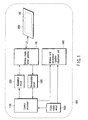
- FIG. 1 is a block diagram showing an example of the schematic arrangement of a wireless communication device (to be referred to as a wireless reader/writer hereinafter) according to the embodiment of the present invention.
- a wireless reader/writer 1000 comprises a wireless reader/writer antenna (main body antenna) 100, control processor 1100, modulation circuit 1200, demodulation circuit 1300, wireless card conveyance/position adjustment unit 1400, and power supply circuit 1500.
- the wireless reader/writer 1000 assumes communication in a communication environment at a distance of 20 mm or less between the antenna plane of the wireless reader/writer antenna 100 and that of a wireless card antenna 200.
- the control processor 1100 instructs the wireless card conveyance/position adjustment unit 1400 to convey a wireless card 2000 to a predetermined position.
- the wireless card conveyance/position adjustment unit 1400 conveys the wireless card 2000 in accordance with the instruction from the control processor 1100.
- the control processor 1100 creates transmission data to the wireless card 2000.
- the modulation circuit 1200 modulates the transmission data, and converts it into a transmission signal.
- the transmission signal is transmitted from the wireless reader/writer antenna 100 to the wireless card 2000.
- a response signal output from the wireless card antenna 200 of the wireless card 2000 is received by the wireless reader/writer antenna 100.
- the demodulation circuit 1300 demodulates the received response signal.
- the control processor 1100 processes the demodulated response signal, and instructs each unit on the next process.
- the power supply circuit 1500 supplies power to each unit of the wireless reader/writer 1000.
- the resonant frequency of the wireless reader/writer antenna 100 is f 0 around the communication frequency used to communicate with the wireless card 2000, as represented by the solid line (case 1) in FIG. 5.
- the antenna resonant frequency of the wireless reader/writer antenna 100 becomes f b , and greatly deviates from f 0 around the communication frequency used to communicate with the wireless card 2000, as represented by the dotted line (case 2) in FIG. 5.
- the wireless reader/writer 1000 and wireless card 2000 are formed with antenna shapes unique to their manufacturers. In some rare occasions, cross coupling between the antennas becomes strong, as described above.
- the antenna characteristic of the wireless reader/writer 1000 varies more than expected, and the resonant frequency changes to a frequency not suitable for communication with the wireless card 2000. In this case, the wireless reader/writer 1000 cannot receive any response from the wireless card 2000, failing in communication.
- the shift of the positions of the two antennas means an increase in the relative distance between them. Since the wireless card 2000 does not have any battery, its operating power depends on transmission radio waves from the wireless reader/writer 1000. That is, the wireless card 2000 receives transmission radio waves from the wireless reader/writer 1000, and converts them into power. Thus, if the relative distance between the wireless reader/writer 1000 and the wireless card 2000 becomes large, the wireless card 2000 may become short of operating power.
- the optimal positional relationship between the wireless reader/writer antenna 100 and the wireless card antenna 200 for normal communication between the wireless reader/writer 1000 and the wireless card 2000 changes depending on the shapes and LSI characteristics of various wireless card antennas 200.
- the wireless communication device (wireless reader/writer 1000) and wireless communication method of the present invention implement normal communication with various types of wireless cards 2000 by properly adjusting the position of the wireless card antenna 200, as needed.
- the wireless card conveyance/position adjustment unit 1400 of the wireless reader/writer 1000 can set a plurality of types of positional relationships between the wireless reader/writer antenna 100 and the wireless card antenna 200.
- the wireless card conveyance/position adjustment unit 1400 can receive the wireless card 2000 and convey the received wireless card 2000 to wireless card antenna position A, wireless card antenna position B, and wireless card antenna position C.
- the wireless card conveyance/position adjustment unit 1400 can change the positional relationship between the wireless reader/writer antenna 100 and the wireless card antenna 200, as needed. This can reduce the influence of cross coupling between the wireless reader/writer antenna 100 and the wireless card antenna 200 on their antenna characteristics. Consequently, one wireless reader/writer 1000 can appropriately communicate with various wireless cards 2000.
- wireless card antenna position A Details of wireless card antenna position A, wireless card antenna position B, and wireless card antenna position C are as follows.
- the antenna planes of the wireless reader/writer antenna 100 and wireless card antenna 200 are parallel to each other.
- Wireless card antenna position B at this position, the center (barycenter) of the antenna plane of the wireless card antenna 200 is located on the perpendicular to an antenna plane passing through the center (barycenter) of the antenna plane of the wireless reader/writer antenna 100.
- Wireless card antenna position A at this position, the wireless card 2000 slides parallel in a direction opposite to the card insertion direction from wireless card antenna position B. For example, as shown in FIG. 6, the wireless card 2000 slides by a distance a from wireless card antenna position B.
- Wireless card antenna position C at this position, the wireless card 2000 slides parallel in the card insertion direction from wireless card antenna position B. For example, as shown in FIG. 6, the wireless card 2000 slides by a distance c from wireless card antenna position B.
- FIG. 7 is a flowchart showing the overall positional relationship change process.
- FIG. 8 is a flowchart showing a partial process in the positional relationship change process in FIG. 7.
- a method of adjusting the positional relationship between the wireless reader/writer antenna 100 and the wireless card antenna 200 by adjusting the position of the wireless card 2000, i.e., that of the wireless card antenna 200 will be exemplified.
- the positional relationship may be adjusted by adjusting the position of the wireless reader/writer antenna 100.
- the positional relationship may also be adjusted by adjusting the positions of the wireless reader/writer antenna 100 and wireless card antenna 200.
- the wireless card conveyance/position adjustment unit 1400 receives the wireless card 2000 (YES in ST11)
- the positional relationship between the wireless reader/writer antenna 100 and the wireless card antenna 200 is adjusted, as needed.
- a case (YES in ST12) in which the flow does not advance to a positional relationship adjustment process based on communication log information will be explained first. The communication log information will be described later.
- the wireless card conveyance/position adjustment unit 1400 sets the wireless card 2000 at wireless card antenna position A (ST13).
- the wireless reader/writer antenna 100 transmits a transmission signal, and the control processor 1100 confirms whether the wireless reader/writer 1000 can normally communicate with the wireless card 2000 set at wireless card antenna position A (ST14). If the wireless reader/writer 1000 and the wireless card 2000 set at wireless card antenna position A can normally communicate with each other (YES in ST14), the control processor 1100 holds communication log information "communication is OK at wireless card antenna position A" (ST19).
- the wireless card conveyance/position adjustment unit 1400 discharges (returns) the received wireless card 2000 (ST21).
- the wireless card conveyance/position adjustment unit 1400 sets the wireless card 2000 at wireless card antenna position B (ST15).
- the wireless reader/writer antenna 100 transmits a transmission signal, and the control processor 1100 confirms whether the wireless reader/writer 1000 can normally communicate with the wireless card 2000 set at wireless card antenna position B (ST16). If the wireless reader/writer 1000 and the wireless card 2000 set at wireless card antenna position B can normally communicate with each other (YES in ST16), the control processor 1100 holds communication log information "communication is OK at wireless card antenna position B" (ST19).
- the wireless card conveyance/position adjustment unit 1400 discharges (returns) the received wireless card 2000 (ST21).
- the wireless card conveyance/position adjustment unit 1400 sets the wireless card 2000 at wireless card antenna position C (ST17).
- the wireless reader/writer antenna 100 transmits a transmission signal, and the control processor 1100 confirms whether the wireless reader/writer 1000 can normally communicate with the wireless card 2000 set at wireless card antenna position C (ST18). If the wireless reader/writer 1000 and the wireless card 2000 set at wireless card antenna position C can normally communicate with each other (YES in ST18), the control processor 1100 holds communication log information "communication is OK at wireless card antenna position C" (ST19).
- the wireless card conveyance/position adjustment unit 1400 discharges (returns) the received wireless card 2000 (ST21).
- the wireless reader/writer 1000 and the wireless card 2000 set at wireless card antenna position C cannot normally communicate with each other (NO in ST18), that is, if the wireless reader/writer 1000 and wireless card 2000 cannot normally communicate with each other even by setting the wireless card 2000 at wireless card antenna position A, wireless card antenna position B, or wireless card antenna position C, a communication error occurs (ST20), and the wireless card conveyance/position adjustment unit 1400 discharges (returns) the received wireless card 2000 (ST21).
- the positional relationship adjustment process based on communication log information will be explained with reference to the flowchart shown in FIG. 8.
- the wireless reader/writer 1000 and wireless card 2000 normally communicate with each other in previous communication, as shown in FIG. 7, their positional relationship and communication result are held as communication log information in ST19.
- the communication log information is utilized to efficiently select and set the wireless card antenna position. If the wireless reader/writer 1000 and wireless card 2000 normally communicate with each other at least once in previous communication, subsequent communication can use the communication log information (YES in ST12). That is, the positional relationship adjustment process based on the communication log information can be executed (ST22).
- the wireless card conveyance/position adjustment unit 1400 preferentially (first) sets the wireless card 2000 at wireless card antenna position A on the basis of the communication log information (ST2204).
- the wireless reader/writer antenna 100 transmits a transmission signal, and the control processor 1100 confirms whether the wireless reader/writer 1000 can normally communicate with the wireless card 2000 set at wireless card antenna position A (ST2205). If the wireless reader/writer 1000 and the wireless card 2000 set at wireless card antenna position A can normally communicate with each other (YES in ST2205), the control processor 1100 updates the communication log information (ST2216).
- control processor 1100 holds communication log information "communication is OK at wireless card antenna position A".
- the wireless reader/writer 1000 often uses a wireless card 2000 manufactured by the same manufacturer as that of the wireless reader/writer 1000. Normal communication can be efficiently implemented in the next communication by preferentially setting the position represented by the communication log information at which previous communication can be normally established.
- the wireless card conveyance/position adjustment unit 1400 sets the wireless card 2000 at wireless card antenna position B (ST2206).
- the wireless reader/writer antenna 100 transmits a transmission signal, and the control processor 1100 confirms whether the wireless reader/writer 1000 can normally communicate with the wireless card 2000 set at wireless card antenna position B (ST2207). If the wireless reader/writer 1000 and the wireless card 2000 set at wireless card antenna position B can normally communicate with each other (YES in ST2207), the control processor 1100 updates the communication log information (ST2216). That is, the control processor 1100 holds communication log information "communication is OK at wireless card antenna position B".
- the wireless card conveyance/position adjustment unit 1400 sets the wireless card 2000 at wireless card antenna position C (ST2208).
- the wireless reader/writer antenna 100 transmits a transmission signal, and the control processor 1100 confirms whether the wireless reader/writer 1000 can normally communicate with the wireless card 2000 set at wireless card antenna position C (ST2209). If the wireless reader/writer 1000 and the wireless card 2000 set at wireless card antenna position C can normally communicate with each other (YES in ST2209), the control processor 1100 updates the communication log information (ST2216). That is, the control processor 1100 holds communication log information "communication is OK at wireless card antenna position C".
- the wireless card conveyance/position adjustment unit 1400 preferentially (first) sets the wireless card 2000 at wireless card antenna position B on the basis of the communication log information (ST2206).
- the wireless reader/writer antenna 100 transmits a transmission signal, and the control processor 1100 confirms whether the wireless reader/writer 1000 can normally communicate with the wireless card 2000 set at wireless card antenna position B (ST2207). If the wireless reader/writer 1000 and the wireless card 2000 set at wireless card antenna position B can normally communicate with each other (YES in ST2207), the control processor 1100 updates the communication log information (ST2216). That is, the control processor 1100 holds communication log information "communication is OK at wireless card antenna position B".
- the wireless card conveyance/position adjustment unit 1400 sets the wireless card 2000 at wireless card antenna position C (ST2208).
- the wireless reader/writer antenna 100 transmits a transmission signal, and the control processor 1100 confirms whether the wireless reader/writer 1000 can normally communicate with the wireless card 2000 set at wireless card antenna position C (ST2209). If the wireless reader/writer 1000 and the wireless card 2000 set at wireless card antenna position C can normally communicate with each other (YES in ST2209), the control processor 1100 updates the communication log information (ST2216). That is, the control processor 1100 holds communication log information "communication is OK at wireless card antenna position C".
- the wireless card conveyance/position adjustment unit 1400 sets the wireless card 2000 at wireless card antenna position A (ST2211).
- the wireless reader/writer antenna 100 transmits a transmission signal, and the control processor 1100 confirms whether the wireless reader/writer 1000 can normally communicate with the wireless card 2000 set at wireless card antenna position A (ST2212). If the wireless reader/writer 1000 and the wireless card 2000 set at wireless card antenna position A can normally communicate with each other (YES in ST2212), the control processor 1100 updates the communication log information (ST2216). That is, the control processor 1100 holds communication log information "communication is OK at wireless card antenna position A".
- the wireless card conveyance/position adjustment unit 1400 preferentially (first) sets the wireless card 2000 at wireless card antenna position C on the basis of the communication log information (ST2208).
- the wireless reader/writer antenna 100 transmits a transmission signal, and the control processor 1100 confirms whether the wireless reader/writer 1000 can normally communicate with the wireless card 2000 set at wireless card antenna position C (ST2209). If the wireless reader/writer 1000 and the wireless card 2000 set at wireless card antenna position C can normally communicate with each other (YES in ST2209), the control processor 1100 updates the communication log information (ST2216). That is, the control processor 1100 holds communication log information "communication is OK at wireless card antenna position C".
- the wireless card conveyance/position adjustment unit 1400 sets the wireless card 2000 at wireless card antenna position A (ST2211).
- the wireless reader/writer antenna 100 transmits a transmission signal, and the control processor 1100 confirms whether the wireless reader/writer 1000 can normally communicate with the wireless card 2000 set at wireless card antenna position A (ST2212). If the wireless reader/writer 1000 and the wireless card 2000 set at wireless card antenna position A can normally communicate with each other (YES in ST2212), the control processor 1100 updates the communication log information (ST2216). That is, the control processor 1100 holds communication log information "communication is OK at wireless card antenna position A".
- the wireless card conveyance/position adjustment unit 1400 sets the wireless card 2000 at wireless card antenna position B (ST2214).
- the wireless reader/writer antenna 100 transmits a transmission signal, and the control processor 1100 confirms whether the wireless reader/writer 1000 can normally communicate with the wireless card 2000 set at wireless card antenna position B (ST2215). If the wireless reader/writer 1000 and the wireless card 2000 set at wireless card antenna position B can normally communicate with each other (YES in ST2215), the control processor 1100 updates the communication log information (ST2216). That is, the control processor 1100 holds communication log information "communication is OK at wireless card antenna position B".
- Adjustment of the antenna positional relationship in the vertical direction by the wireless communication device (wireless reader/writer 1000) and wireless communication method of the present invention will be explained. Adjustment in the parallel direction has been described, and adjustment in the vertical direction (to be described below) can also be applied to the present invention.
- the wireless card conveyance/position adjustment unit 1400 can receive the wireless card 2000 and convey the received wireless card 2000 to wireless card antenna position D, wireless card antenna position E, and wireless card antenna position F.
- the wireless card conveyance/position adjustment unit 1400 can change the positional relationship between the wireless reader/writer antenna 100 and the wireless card antenna 200, as needed. This can reduce the influence of cross coupling between the wireless reader/writer antenna 100 and the wireless card antenna 200 on their antenna characteristics. As a result, one wireless reader/writer 1000 can appropriately communicate with various wireless cards 2000.
- wireless card antenna position D Details of wireless card antenna position D, wireless card antenna position E, and wireless card antenna position F are as follows.
- the antenna planes of the wireless reader/writer antenna 100 and wireless card antenna 200 are parallel to each other.
- Wireless card antenna position E at this position, the center (barycenter) of the antenna plane of the wireless card antenna 200 is located on the perpendicular to an antenna plane passing through the center (barycenter) of the antenna plane of the wireless reader/writer antenna 100.
- the distance between the centers of the two antenna planes is a distance e .
- Wireless card antenna position D at this position, the center (barycenter) of the antenna plane of the wireless card antenna 200 is located on the perpendicular to an antenna plane passing through the center (barycenter) of the antenna plane of the wireless reader/writer antenna 100.
- the distance between the centers of the two antenna planes is a distance d (distance d ⁇ distance e).
- Wireless card antenna position F at this position, the center (barycenter) of the antenna plane of the wireless card antenna 200 is located on the perpendicular to an antenna plane passing through the center (barycenter) of the antenna plane of the wireless reader/writer antenna 100.
- the distance between the centers of the two antenna planes is a distance f (distance f > distance e).
- the wireless reader/writer antenna 100 may be greatly influenced by the antenna characteristic from the wireless card antenna 200 in the order of d > e > f.
- the present invention can adopt a combination of the above-mentioned adjustment in the parallel direction and adjustment in the vertical direction. Also in this case, the influence of cross coupling between the wireless reader/writer antenna 100 and the wireless card antenna 200 on their antenna characteristics can be reduced.
- One wireless reader/writer 1000 can properly communicate with various wireless cards 2000.
- the positional relationship between the wireless reader/writer antenna 100 and the wireless card antenna 200 is changed by changing the position of the wireless card 2000, i.e., that of the wireless card antenna 200.
- the present invention is not limited to this.
- the position of the wireless card 2000 may be fixed, and only that of the wireless reader/writer antenna 100 may be changed.
- the positions of both the wireless card 2000 and wireless reader/writer antenna 100 may be changed.
- the wireless communication device wireless reader/writer 1000
- wireless communication method of the present invention can set a plurality of types of antenna positional relationships.
- the probability of communication errors can be decreased for various types of wireless cards, and the wireless communication device can appropriately communicate with various types of wireless cards.
- the process time can be shortened in an environment where many identical wireless cards are available.
- the present invention can provide a wireless communication device and wireless communication method capable of solving a communication error caused by the antenna characteristic and realizing a normal communication environment.
Landscapes
- Engineering & Computer Science (AREA)
- Health & Medical Sciences (AREA)
- Toxicology (AREA)
- Physics & Mathematics (AREA)
- Computer Networks & Wireless Communication (AREA)
- Electromagnetism (AREA)
- General Health & Medical Sciences (AREA)
- Artificial Intelligence (AREA)
- Computer Vision & Pattern Recognition (AREA)
- General Physics & Mathematics (AREA)
- Theoretical Computer Science (AREA)
- Near-Field Transmission Systems (AREA)
Abstract
Description
- The present invention relates to a wireless communication device which communicates with a wireless card or wireless tag used for a credit card, reward card, or individual identification medium (e.g., a bankbook, employee card, or passport), and a wireless communication method applied to the wireless communication device.
- Recently, wireless cards have widely spread for reasons of information security and portability. Organizations such as ISO standardize the communication method so that wireless readers/writers and wireless cards available from various manufacturers can be utilized without any problem. For example, Jpn. Pat. Appln. KOKAI Publication No. 9-179954 discloses a technique for a wireless information processing apparatus which reads/writes data from/on a portable wireless card via a wireless communication medium.
- However, when the transmission/reception antenna of the wireless reader/writer and the antenna of the wireless card are in tight contact with each other and have a similar shape, cross coupling between the antennas becomes strong, and their antenna characteristics influence each other. The antenna characteristic of the wireless reader/writer may greatly deviate from the communication frequency of the wireless card. Along with this, the wireless reader/writer may not normally receive a response from the wireless card. That is, the wireless reader/writer and wireless card which meet the standard of ISO or the like may not be able to communicate with each other.
- It is an object of the present invention to provide a wireless communication device and wireless communication method capable of solving a communication error caused by the antenna characteristic and realizing a normal communication environment.
- A wireless communication device according to an aspect of the present invention comprises a main body antenna to communicate with an antenna of a wireless card, and antenna position setting means capable of setting a plurality of types of positional relationships between the antenna of the wireless card and the main body antenna.
- A wireless communication method according to another aspect of the present invention comprises performing communication between an antenna of a wireless card and a main body antenna which are set to a predetermined positional relationship, changing the positional relationship between the antenna of the wireless card and the main body antenna, as needed, and performing communication between the antenna of the wireless card and the main body antenna.
- This summary of the invention does not necessarily describe all necessary features so that the invention may also be a sub-combination of these described features.
- The invention can be more fully understood from the following detailed description when taken in conjunction with the accompanying drawings, in which:
- FIG. 1 is a block diagram showing an example of the schematic arrangement of a wireless communication device (wireless reader/writer) according to an embodiment of the present invention;
- FIG. 2 is a view showing an example of a state in which no wireless card antenna exists near the wireless reader/writer antenna;
- FIG. 3 is a view showing an example of a state in which predetermined conditions are met and cross coupling between the wireless reader/writer antenna and the wireless card antenna becomes strong and greatly influences their antenna characteristics;
- FIG. 4 is a view showing an example of a state in which the wireless card antenna exists near the wireless reader/writer antenna but does not greatly influence their antenna characteristics;
- FIG. 5 is a graph showing an example of the frequency characteristic of the wireless reader/writer antenna in the states shown in FIGS. 2 to 4;
- FIG. 6 is a view for explaining wireless card antenna position A, wireless card antenna position B, and wireless card antenna position C;
- FIG. 7 is a flowchart showing an overall positional relationship change process;
- FIG. 8 is a flowchart showing a partial process in the positional relationship change process in FIG. 7, i.e., a positional relationship adjustment process based on communication log information; and
- FIG. 9 is a view for explaining wireless card antenna position D, wireless card antenna position E, and wireless card antenna position F.
-
- A preferred embodiment of the present invention will be described below with reference to the several views of the accompanying drawing.
- FIG. 1 is a block diagram showing an example of the schematic arrangement of a wireless communication device (to be referred to as a wireless reader/writer hereinafter) according to the embodiment of the present invention. A wireless reader/
writer 1000 comprises a wireless reader/writer antenna (main body antenna) 100,control processor 1100,modulation circuit 1200,demodulation circuit 1300, wireless card conveyance/position adjustment unit 1400, andpower supply circuit 1500. - The wireless reader/
writer 1000 assumes communication in a communication environment at a distance of 20 mm or less between the antenna plane of the wireless reader/writer antenna 100 and that of awireless card antenna 200. Thecontrol processor 1100 instructs the wireless card conveyance/position adjustment unit 1400 to convey awireless card 2000 to a predetermined position. The wireless card conveyance/position adjustment unit 1400 conveys thewireless card 2000 in accordance with the instruction from thecontrol processor 1100. - The
control processor 1100 creates transmission data to thewireless card 2000. Themodulation circuit 1200 modulates the transmission data, and converts it into a transmission signal. The transmission signal is transmitted from the wireless reader/writer antenna 100 to thewireless card 2000. - A response signal output from the
wireless card antenna 200 of thewireless card 2000 is received by the wireless reader/writer antenna 100. Thedemodulation circuit 1300 demodulates the received response signal. Thecontrol processor 1100 processes the demodulated response signal, and instructs each unit on the next process. - The
power supply circuit 1500 supplies power to each unit of the wireless reader/writer 1000. - The resonant frequency variation phenomenon in the wireless reader/
writer antenna 100 of the wireless reader/writer 1000 and theantenna 200 of thewireless card 2000 will be explained with reference to FIGS. 2 to 4. - When the
wireless card antenna 200 does not exist near the wireless reader/writer antenna 100, as shown in FIG. 2, the resonant frequency of the wireless reader/writer antenna 100 is f0 around the communication frequency used to communicate with thewireless card 2000, as represented by the solid line (case 1) in FIG. 5. - When the following conditions (1) to (4) are met between the wireless reader/
writer antenna 100 and thewireless card antenna 200, as shown in FIG. 3 (case 2), cross coupling between the antennas becomes strong and greatly influences their antenna characteristics. - (1) Arrangement in which the two antenna planes are parallel and close to each other.
- (2) Arrangement in which the centers of the two antenna planes overlap each other or are close to each other.
- (3) The shapes of the two antennas are similar.
- (4) The sizes of the two antennas are almost equal.
-
- Under these conditions, the antenna resonant frequency of the wireless reader/
writer antenna 100 becomes fb, and greatly deviates from f0 around the communication frequency used to communicate with thewireless card 2000, as represented by the dotted line (case 2) in FIG. 5. - The wireless reader/
writer 1000 andwireless card 2000 are formed with antenna shapes unique to their manufacturers. In some rare occasions, cross coupling between the antennas becomes strong, as described above. The antenna characteristic of the wireless reader/writer 1000 varies more than expected, and the resonant frequency changes to a frequency not suitable for communication with thewireless card 2000. In this case, the wireless reader/writer 1000 cannot receive any response from thewireless card 2000, failing in communication. - When the two antennas are shifted so that the centers of the antenna planes of the
wireless card antenna 200 and wireless reader/writer antenna 100 do not overlap each other, as shown in FIG. 4 (case 3), cross coupling between the antennas reduces, and the resonant frequency of the wireless reader/writer antenna 100 changes to fa which is almost the same as one obtained when only the wireless reader/writer 1000 is arranged, as represented by the dotted line (case 3) in FIG. 5. As a result, the wireless reader/writer antenna 100 can receive a response from thewireless card 2000 and normally communicate with it. - However, the shift of the positions of the two antennas means an increase in the relative distance between them. Since the
wireless card 2000 does not have any battery, its operating power depends on transmission radio waves from the wireless reader/writer 1000. That is, thewireless card 2000 receives transmission radio waves from the wireless reader/writer 1000, and converts them into power. Thus, if the relative distance between the wireless reader/writer 1000 and thewireless card 2000 becomes large, thewireless card 2000 may become short of operating power. - From this, the optimal positional relationship between the wireless reader/
writer antenna 100 and thewireless card antenna 200 for normal communication between the wireless reader/writer 1000 and thewireless card 2000 changes depending on the shapes and LSI characteristics of variouswireless card antennas 200. - The wireless communication device (wireless reader/writer 1000) and wireless communication method of the present invention implement normal communication with various types of
wireless cards 2000 by properly adjusting the position of thewireless card antenna 200, as needed. - Adjustment of the antenna positional relationship in the parallel direction by the wireless communication device (wireless reader/writer 1000) and wireless communication method of the present invention will be explained.
- The wireless card conveyance/
position adjustment unit 1400 of the wireless reader/writer 1000 can set a plurality of types of positional relationships between the wireless reader/writer antenna 100 and thewireless card antenna 200. For example, as shown in FIG. 6, the wireless card conveyance/position adjustment unit 1400 can receive thewireless card 2000 and convey the receivedwireless card 2000 to wireless card antenna position A, wireless card antenna position B, and wireless card antenna position C. In other words, the wireless card conveyance/position adjustment unit 1400 can change the positional relationship between the wireless reader/writer antenna 100 and thewireless card antenna 200, as needed. This can reduce the influence of cross coupling between the wireless reader/writer antenna 100 and thewireless card antenna 200 on their antenna characteristics. Consequently, one wireless reader/writer 1000 can appropriately communicate with variouswireless cards 2000. - Details of wireless card antenna position A, wireless card antenna position B, and wireless card antenna position C are as follows.
- As a premise, the antenna planes of the wireless reader/
writer antenna 100 andwireless card antenna 200 are parallel to each other. - Wireless card antenna position B: at this position, the center (barycenter) of the antenna plane of the
wireless card antenna 200 is located on the perpendicular to an antenna plane passing through the center (barycenter) of the antenna plane of the wireless reader/writer antenna 100. - Wireless card antenna position A: at this position, the
wireless card 2000 slides parallel in a direction opposite to the card insertion direction from wireless card antenna position B. For example, as shown in FIG. 6, thewireless card 2000 slides by a distance a from wireless card antenna position B. - Wireless card antenna position C: at this position, the
wireless card 2000 slides parallel in the card insertion direction from wireless card antenna position B. For example, as shown in FIG. 6, thewireless card 2000 slides by a distance c from wireless card antenna position B. - A process of changing the positional relationship between the wireless reader/
writer antenna 100 and thewireless card antenna 200 according to the embodiment of the present invention will be explained with reference to FIGS. 7 and 8. FIG. 7 is a flowchart showing the overall positional relationship change process. FIG. 8 is a flowchart showing a partial process in the positional relationship change process in FIG. 7. - A method of adjusting the positional relationship between the wireless reader/
writer antenna 100 and thewireless card antenna 200 by adjusting the position of thewireless card 2000, i.e., that of thewireless card antenna 200 will be exemplified. However, the present invention is not limited to this. For example, the positional relationship may be adjusted by adjusting the position of the wireless reader/writer antenna 100. The positional relationship may also be adjusted by adjusting the positions of the wireless reader/writer antenna 100 andwireless card antenna 200. - As shown in FIG. 7, if the
wireless card 2000 is inserted into the wireless reader/writer 1000, i.e., the wireless card conveyance/position adjustment unit 1400 receives the wireless card 2000 (YES in ST11), the positional relationship between the wireless reader/writer antenna 100 and thewireless card antenna 200 is adjusted, as needed. A case (YES in ST12) in which the flow does not advance to a positional relationship adjustment process based on communication log information will be explained first. The communication log information will be described later. - For example, the wireless card conveyance/
position adjustment unit 1400 sets thewireless card 2000 at wireless card antenna position A (ST13). The wireless reader/writer antenna 100 transmits a transmission signal, and thecontrol processor 1100 confirms whether the wireless reader/writer 1000 can normally communicate with thewireless card 2000 set at wireless card antenna position A (ST14). If the wireless reader/writer 1000 and thewireless card 2000 set at wireless card antenna position A can normally communicate with each other (YES in ST14), thecontrol processor 1100 holds communication log information "communication is OK at wireless card antenna position A" (ST19). The wireless card conveyance/position adjustment unit 1400 discharges (returns) the received wireless card 2000 (ST21). - If the wireless reader/
writer 1000 and thewireless card 2000 set at wireless card antenna position A cannot normally communicate with each other (NO in ST14), the wireless card conveyance/position adjustment unit 1400 sets thewireless card 2000 at wireless card antenna position B (ST15). The wireless reader/writer antenna 100 transmits a transmission signal, and thecontrol processor 1100 confirms whether the wireless reader/writer 1000 can normally communicate with thewireless card 2000 set at wireless card antenna position B (ST16). If the wireless reader/writer 1000 and thewireless card 2000 set at wireless card antenna position B can normally communicate with each other (YES in ST16), thecontrol processor 1100 holds communication log information "communication is OK at wireless card antenna position B" (ST19). The wireless card conveyance/position adjustment unit 1400 discharges (returns) the received wireless card 2000 (ST21). - If the wireless reader/
writer 1000 and thewireless card 2000 set at wireless card antenna position B cannot normally communicate with each other (NO in ST16), the wireless card conveyance/position adjustment unit 1400 sets thewireless card 2000 at wireless card antenna position C (ST17). The wireless reader/writer antenna 100 transmits a transmission signal, and thecontrol processor 1100 confirms whether the wireless reader/writer 1000 can normally communicate with thewireless card 2000 set at wireless card antenna position C (ST18). If the wireless reader/writer 1000 and thewireless card 2000 set at wireless card antenna position C can normally communicate with each other (YES in ST18), thecontrol processor 1100 holds communication log information "communication is OK at wireless card antenna position C" (ST19). The wireless card conveyance/position adjustment unit 1400 discharges (returns) the received wireless card 2000 (ST21). - If the wireless reader/
writer 1000 and thewireless card 2000 set at wireless card antenna position C cannot normally communicate with each other (NO in ST18), that is, if the wireless reader/writer 1000 andwireless card 2000 cannot normally communicate with each other even by setting thewireless card 2000 at wireless card antenna position A, wireless card antenna position B, or wireless card antenna position C, a communication error occurs (ST20), and the wireless card conveyance/position adjustment unit 1400 discharges (returns) the received wireless card 2000 (ST21). - As described above, even when the wireless reader/
writer 1000 andwireless card 2000 cannot normally communicate with each other at a specific wireless card antenna position, a communication error by the antenna characteristic can be solved by position adjustment to implement normal communication. - The positional relationship adjustment process based on communication log information will be explained with reference to the flowchart shown in FIG. 8. When the wireless reader/
writer 1000 andwireless card 2000 normally communicate with each other in previous communication, as shown in FIG. 7, their positional relationship and communication result are held as communication log information in ST19. In subsequent communication, the communication log information is utilized to efficiently select and set the wireless card antenna position. If the wireless reader/writer 1000 andwireless card 2000 normally communicate with each other at least once in previous communication, subsequent communication can use the communication log information (YES in ST12). That is, the positional relationship adjustment process based on the communication log information can be executed (ST22). - For example, if the communication log information represents that the position at which previous communication can be normally achieved is wireless card antenna position A (YES in ST2201), the wireless card conveyance/
position adjustment unit 1400 preferentially (first) sets thewireless card 2000 at wireless card antenna position A on the basis of the communication log information (ST2204). The wireless reader/writer antenna 100 transmits a transmission signal, and thecontrol processor 1100 confirms whether the wireless reader/writer 1000 can normally communicate with thewireless card 2000 set at wireless card antenna position A (ST2205). If the wireless reader/writer 1000 and thewireless card 2000 set at wireless card antenna position A can normally communicate with each other (YES in ST2205), thecontrol processor 1100 updates the communication log information (ST2216). That is, thecontrol processor 1100 holds communication log information "communication is OK at wireless card antenna position A". The wireless reader/writer 1000 often uses awireless card 2000 manufactured by the same manufacturer as that of the wireless reader/writer 1000. Normal communication can be efficiently implemented in the next communication by preferentially setting the position represented by the communication log information at which previous communication can be normally established. - If the wireless reader/
writer 1000 and thewireless card 2000 set at wireless card antenna position A cannot normally communicate with each other (NO in ST2205), the wireless card conveyance/position adjustment unit 1400 sets thewireless card 2000 at wireless card antenna position B (ST2206). The wireless reader/writer antenna 100 transmits a transmission signal, and thecontrol processor 1100 confirms whether the wireless reader/writer 1000 can normally communicate with thewireless card 2000 set at wireless card antenna position B (ST2207). If the wireless reader/writer 1000 and thewireless card 2000 set at wireless card antenna position B can normally communicate with each other (YES in ST2207), thecontrol processor 1100 updates the communication log information (ST2216). That is, thecontrol processor 1100 holds communication log information "communication is OK at wireless card antenna position B". - If the wireless reader/
writer 1000 and thewireless card 2000 set at wireless card antenna position B cannot normally communicate with each other (NO in ST2207), the wireless card conveyance/position adjustment unit 1400 sets thewireless card 2000 at wireless card antenna position C (ST2208). The wireless reader/writer antenna 100 transmits a transmission signal, and thecontrol processor 1100 confirms whether the wireless reader/writer 1000 can normally communicate with thewireless card 2000 set at wireless card antenna position C (ST2209). If the wireless reader/writer 1000 and thewireless card 2000 set at wireless card antenna position C can normally communicate with each other (YES in ST2209), thecontrol processor 1100 updates the communication log information (ST2216). That is, thecontrol processor 1100 holds communication log information "communication is OK at wireless card antenna position C". - If the wireless reader/
writer 1000 and thewireless card 2000 set at wireless card antenna position C cannot normally communicate with each other (NO in ST2209), that is, if the wireless reader/writer 1000 andwireless card 2000 cannot normally communicate with each other even by setting thewireless card 2000 at wireless card antenna position A, wireless card antenna position B, or wireless card antenna position C (YES in ST2210), a communication error occurs (ST2217). - If the communication log information represents that the position at which previous communication can be normally achieved is wireless card antenna position B (YES in ST2202), the wireless card conveyance/
position adjustment unit 1400 preferentially (first) sets thewireless card 2000 at wireless card antenna position B on the basis of the communication log information (ST2206). The wireless reader/writer antenna 100 transmits a transmission signal, and thecontrol processor 1100 confirms whether the wireless reader/writer 1000 can normally communicate with thewireless card 2000 set at wireless card antenna position B (ST2207). If the wireless reader/writer 1000 and thewireless card 2000 set at wireless card antenna position B can normally communicate with each other (YES in ST2207), thecontrol processor 1100 updates the communication log information (ST2216). That is, thecontrol processor 1100 holds communication log information "communication is OK at wireless card antenna position B". - If the wireless reader/
writer 1000 and thewireless card 2000 set at wireless card antenna position B cannot normally communicate with each other (NO in ST2207), the wireless card conveyance/position adjustment unit 1400 sets thewireless card 2000 at wireless card antenna position C (ST2208). The wireless reader/writer antenna 100 transmits a transmission signal, and thecontrol processor 1100 confirms whether the wireless reader/writer 1000 can normally communicate with thewireless card 2000 set at wireless card antenna position C (ST2209). If the wireless reader/writer 1000 and thewireless card 2000 set at wireless card antenna position C can normally communicate with each other (YES in ST2209), thecontrol processor 1100 updates the communication log information (ST2216). That is, thecontrol processor 1100 holds communication log information "communication is OK at wireless card antenna position C". - Even if the wireless reader/
writer 1000 and thewireless card 2000 set at wireless card antenna position C cannot normally communicate with each other (NO in ST2207), a communication error has not been confirmed at all wireless card antenna positions (NO in ST2210). Thus, the wireless card conveyance/position adjustment unit 1400 sets thewireless card 2000 at wireless card antenna position A (ST2211). The wireless reader/writer antenna 100 transmits a transmission signal, and thecontrol processor 1100 confirms whether the wireless reader/writer 1000 can normally communicate with thewireless card 2000 set at wireless card antenna position A (ST2212). If the wireless reader/writer 1000 and thewireless card 2000 set at wireless card antenna position A can normally communicate with each other (YES in ST2212), thecontrol processor 1100 updates the communication log information (ST2216). That is, thecontrol processor 1100 holds communication log information "communication is OK at wireless card antenna position A". - If the wireless reader/
writer 1000 and thewireless card 2000 set at wireless card antenna position A cannot normally communicate with each other (NO in ST2212), that is, if the wireless reader/writer 1000 andwireless card 2000 cannot normally communicate with each other even by setting thewireless card 2000 at wireless card antenna position B, wireless card antenna position C, or wireless card antenna position A (YES in ST2213), a communication error occurs (ST2217). - If the communication log information represents that the position at which previous communication can be normally achieved is wireless card antenna position C (YES in ST2203), the wireless card conveyance/
position adjustment unit 1400 preferentially (first) sets thewireless card 2000 at wireless card antenna position C on the basis of the communication log information (ST2208). The wireless reader/writer antenna 100 transmits a transmission signal, and thecontrol processor 1100 confirms whether the wireless reader/writer 1000 can normally communicate with thewireless card 2000 set at wireless card antenna position C (ST2209). If the wireless reader/writer 1000 and thewireless card 2000 set at wireless card antenna position C can normally communicate with each other (YES in ST2209), thecontrol processor 1100 updates the communication log information (ST2216). That is, thecontrol processor 1100 holds communication log information "communication is OK at wireless card antenna position C". - Even if the wireless reader/
writer 1000 and thewireless card 2000 set at wireless card antenna position C cannot normally communicate with each other (NO in ST2209), a communication error has not been confirmed at all wireless card antenna positions (NO in ST2210). Thus, the wireless card conveyance/position adjustment unit 1400 sets thewireless card 2000 at wireless card antenna position A (ST2211). The wireless reader/writer antenna 100 transmits a transmission signal, and thecontrol processor 1100 confirms whether the wireless reader/writer 1000 can normally communicate with thewireless card 2000 set at wireless card antenna position A (ST2212). If the wireless reader/writer 1000 and thewireless card 2000 set at wireless card antenna position A can normally communicate with each other (YES in ST2212), thecontrol processor 1100 updates the communication log information (ST2216). That is, thecontrol processor 1100 holds communication log information "communication is OK at wireless card antenna position A". - Even if the wireless reader/
writer 1000 and thewireless card 2000 set at wireless card antenna position A cannot normally communicate with each other (NO in ST2212), a communication error has not been confirmed at all wireless card antenna positions (NO in ST2213). Thus, the wireless card conveyance/position adjustment unit 1400 sets thewireless card 2000 at wireless card antenna position B (ST2214). The wireless reader/writer antenna 100 transmits a transmission signal, and thecontrol processor 1100 confirms whether the wireless reader/writer 1000 can normally communicate with thewireless card 2000 set at wireless card antenna position B (ST2215). If the wireless reader/writer 1000 and thewireless card 2000 set at wireless card antenna position B can normally communicate with each other (YES in ST2215), thecontrol processor 1100 updates the communication log information (ST2216). That is, thecontrol processor 1100 holds communication log information "communication is OK at wireless card antenna position B". - If the wireless reader/
writer 1000 and thewireless card 2000 set at wireless card antenna position B cannot normally communicate with each other (NO in ST2215), that is, if the wireless reader/writer 1000 andwireless card 2000 cannot normally communicate with each other even by setting thewireless card 2000 at wireless card antenna position C, wireless card antenna position A, or wireless card antenna position B (YES in ST2215), a communication error occurs (ST2217). - Adjustment of the antenna positional relationship in the vertical direction by the wireless communication device (wireless reader/writer 1000) and wireless communication method of the present invention will be explained. Adjustment in the parallel direction has been described, and adjustment in the vertical direction (to be described below) can also be applied to the present invention.
- For example, as shown in FIG. 9, the wireless card conveyance/
position adjustment unit 1400 can receive thewireless card 2000 and convey the receivedwireless card 2000 to wireless card antenna position D, wireless card antenna position E, and wireless card antenna position F. In other words, the wireless card conveyance/position adjustment unit 1400 can change the positional relationship between the wireless reader/writer antenna 100 and thewireless card antenna 200, as needed. This can reduce the influence of cross coupling between the wireless reader/writer antenna 100 and thewireless card antenna 200 on their antenna characteristics. As a result, one wireless reader/writer 1000 can appropriately communicate withvarious wireless cards 2000. - Details of wireless card antenna position D, wireless card antenna position E, and wireless card antenna position F are as follows.
- As a premise, the antenna planes of the wireless reader/
writer antenna 100 andwireless card antenna 200 are parallel to each other. - Wireless card antenna position E: at this position, the center (barycenter) of the antenna plane of the
wireless card antenna 200 is located on the perpendicular to an antenna plane passing through the center (barycenter) of the antenna plane of the wireless reader/writer antenna 100. The distance between the centers of the two antenna planes is a distance e. - Wireless card antenna position D: at this position, the center (barycenter) of the antenna plane of the
wireless card antenna 200 is located on the perpendicular to an antenna plane passing through the center (barycenter) of the antenna plane of the wireless reader/writer antenna 100. The distance between the centers of the two antenna planes is a distance d (distance d < distance e). - Wireless card antenna position F: at this position, the center (barycenter) of the antenna plane of the
wireless card antenna 200 is located on the perpendicular to an antenna plane passing through the center (barycenter) of the antenna plane of the wireless reader/writer antenna 100. The distance between the centers of the two antenna planes is a distance f (distance f > distance e). - When d < e < f, the wireless reader/
writer antenna 100 may be greatly influenced by the antenna characteristic from thewireless card antenna 200 in the order of d > e > f. - The present invention can adopt a combination of the above-mentioned adjustment in the parallel direction and adjustment in the vertical direction. Also in this case, the influence of cross coupling between the wireless reader/
writer antenna 100 and thewireless card antenna 200 on their antenna characteristics can be reduced. One wireless reader/writer 1000 can properly communicate withvarious wireless cards 2000. - In the above description, the positional relationship between the wireless reader/
writer antenna 100 and thewireless card antenna 200 is changed by changing the position of thewireless card 2000, i.e., that of thewireless card antenna 200. However, the present invention is not limited to this. For example, the position of thewireless card 2000 may be fixed, and only that of the wireless reader/writer antenna 100 may be changed. Alternatively, the positions of both thewireless card 2000 and wireless reader/writer antenna 100 may be changed. - As has been described above, the wireless communication device (wireless reader/writer 1000) and wireless communication method of the present invention can set a plurality of types of antenna positional relationships. The probability of communication errors can be decreased for various types of wireless cards, and the wireless communication device can appropriately communicate with various types of wireless cards. By utilizing communication log information, the process time can be shortened in an environment where many identical wireless cards are available.
- The present invention can provide a wireless communication device and wireless communication method capable of solving a communication error caused by the antenna characteristic and realizing a normal communication environment.
- It is explicitly stated that all features disclosed in the description and/or the claims are intended to be disclosed separately and independently from each other for the purpose of original disclosure as well as for the purpose of restricting the claimed invention independent of the composition of the features in the embodiments and/or the claims. It is cxplicitly stated that all value ranges or indications of groups of entities disclose every possible intermediate value or intermediate entity for the purpose of original disclosure as well as for the purpose of restricting the claimed invention, in particular as limits of value ranges.
Claims (10)
- A wireless communication device characterized by comprising:a main body antenna (100) to communicate with an antenna of a wireless card;antenna position setting means (1400) capable of setting a plurality of types of positional relationships between the antenna of the wireless card and the main body antenna;communication means (1100, 1200, 1300) for performing communication between the antenna of the wireless card and the main body antenna which are set to a predetermined positional relationship by the antenna position setting means; andpositional relationship control means (1100) for controlling setting of the positional relationship between the antenna of the wireless card and the main body antenna by the antenna position setting means, as needed on the basis of a communication state by the communication means.
- A device according to claim 1, characterized in that while maintaining a plane of the antenna of the wireless card and a plane of the main body antenna parallel to each other, the antenna position setting means can set the plurality of types of the positional relationships between the antenna of the wireless card and the main body antenna.
- A device according to claim 1 or 2, characterized in that while maintaining a plane of the antenna of the wireless card and a plane of the main body antenna parallel to each other, the antenna position setting means can set the plurality of types of the positional relationships between the antenna of the wireless card and the main body antenna in a direction parallel to the plane of the antenna of the wireless card and the plane of the main body antenna.
- A device according to one of claims 1 to 3, characterized in that while maintaining a plane of the antenna of the wireless card and a plane of the main body antenna parallel to each other, the antenna position setting means can set the plurality of types of the positional relationships between the antenna of the wireless card and the main body antenna in a direction perpendicular to the plane of the antenna of the wireless card and the plane of the main body antenna.
- A device according to one of claims 1 to 4, characterized in that the positional relationship control means stores as communication log information a communication result of the antenna of the wireless card and the main body antenna and the positional relationship between the antenna of the wireless card and the main body antenna in a first communication process, and controls initial setting of the positional relationship between the antenna of the wireless card and the main body antenna on the basis of the communication log information in a second communication process subsequent to the first communication process.
- A wireless communication method characterized by comprising:performing (ST14) communication between an antenna of a wireless card and a main body antenna which are set to a predetermined positional relationship;changing (ST15) the positional relationship between the antenna of the wireless card and the main body antenna, as needed on the basis of a communication state between the antenna of the wireless card and the main body antenna which are set to the predetermined positional relationship; andperforming (ST16) communication between the antenna of the wireless card and the main body antenna which are set to the changed positional relationship.
- A method according to claim 6, characterized in that while a plane of the antenna of the wireless card and a plane of the main body antenna are maintained parallel to each other, the positional relationship between the antenna of the wireless card and the main body antenna is changed.
- A method according to claim 6 or 7, characterized in that while a plane of the antenna of the wireless card and a plane of the main body antenna are maintained parallel to each other, the positional relationship between the antenna of the wireless card and the main body antenna is changed in a direction parallel to the plane of the antenna of the wireless card and the plane of the main body antenna.
- A method according to one of claims 1 to 8,
characterized in that while a plane of the antenna of the wireless card and a plane of the main body antenna are maintained parallel to each other, the positional relationship between the antenna of the wireless card and the main body antenna is changed in a direction perpendicular to the plane of the antenna of the wireless card and the plane of the main body antenna. - A method according to one of claims 1 to 9,
characterized in that a communication result of the antenna of the wireless card and the main body antenna and the positional relationship between the antenna of the wireless card and the main body antenna are stored as communication log information in a first communication process, and initial setting of the positional relationship between the antenna of the wireless card and the main body antenna is controlled on the basis of the communication log information in a second communication process subsequent to the first communication process.
Applications Claiming Priority (2)
| Application Number | Priority Date | Filing Date | Title |
|---|---|---|---|
| JP2003300348A JP2005071102A (en) | 2003-08-25 | 2003-08-25 | Wireless communication device and wireless communication method |
| JP2003300348 | 2003-08-25 |
Publications (2)
| Publication Number | Publication Date |
|---|---|
| EP1510961A1 true EP1510961A1 (en) | 2005-03-02 |
| EP1510961B1 EP1510961B1 (en) | 2006-10-04 |
Family
ID=34101160
Family Applications (1)
| Application Number | Title | Priority Date | Filing Date |
|---|---|---|---|
| EP04019283A Expired - Lifetime EP1510961B1 (en) | 2003-08-25 | 2004-08-13 | Wireless communication device and wireless communication method |
Country Status (5)
| Country | Link |
|---|---|
| US (1) | US7257389B2 (en) |
| EP (1) | EP1510961B1 (en) |
| JP (1) | JP2005071102A (en) |
| DE (1) | DE602004002639T2 (en) |
| SG (1) | SG109570A1 (en) |
Cited By (1)
| Publication number | Priority date | Publication date | Assignee | Title |
|---|---|---|---|---|
| US8511556B2 (en) | 2008-02-29 | 2013-08-20 | Nidec Sankyo Corporation | Card reader |
Families Citing this family (6)
| Publication number | Priority date | Publication date | Assignee | Title |
|---|---|---|---|---|
| JP4799050B2 (en) * | 2005-05-31 | 2011-10-19 | 株式会社サトー | Printing device |
| JP2007213298A (en) * | 2006-02-09 | 2007-08-23 | Sato Corp | RFID printer |
| JP4876236B2 (en) * | 2006-09-01 | 2012-02-15 | 日本電産サンキョー株式会社 | USB communication system, USB device, and abnormality detection method for USB communication system |
| JP5075787B2 (en) * | 2008-10-14 | 2012-11-21 | 株式会社村田製作所 | Card type device |
| JP5670798B2 (en) * | 2011-03-30 | 2015-02-18 | フェリカネットワークス株式会社 | Communication terminal, communication method, and program |
| KR102022867B1 (en) * | 2012-08-07 | 2019-09-20 | 삼성전자 주식회사 | Near field communication circuit and operating method of the same |
Citations (2)
| Publication number | Priority date | Publication date | Assignee | Title |
|---|---|---|---|---|
| JPH10240879A (en) * | 1997-02-25 | 1998-09-11 | Oki Electric Ind Co Ltd | Method for controlling carriage of proximity non-contact ic card |
| EP1096414A2 (en) * | 1999-10-08 | 2001-05-02 | Sankyo Seiki Mfg. Co. Ltd. | IC card reader |
Family Cites Families (8)
| Publication number | Priority date | Publication date | Assignee | Title |
|---|---|---|---|---|
| DE4240238C2 (en) * | 1992-11-30 | 1995-01-05 | Angewandte Digital Elektronik | Device for contactless energy and data transmission for single-coil and double-coil systems |
| JPH09179954A (en) | 1995-12-26 | 1997-07-11 | Toshiba Corp | Radio information transmission device |
| SG54559A1 (en) * | 1996-09-13 | 1998-11-16 | Hitachi Ltd | Power transmission system ic card and information communication system using ic card |
| US6173897B1 (en) | 1998-07-27 | 2001-01-16 | John W. Halpern | Universal card interface module for contact free cards |
| JP2000251038A (en) * | 1999-03-03 | 2000-09-14 | Toshiba Corp | Wireless information storage medium and method of arranging wireless information storage medium |
| EP1136960A1 (en) * | 2000-03-24 | 2001-09-26 | Infineon Technologies AG | Individual arrangement |
| JP2002056361A (en) | 2000-08-09 | 2002-02-20 | Hitachi Maxell Ltd | Non-contact type information recording medium reader and non-contact type information recording medium information processing system |
| JP2003141464A (en) | 2001-11-05 | 2003-05-16 | Denso Corp | Reader / writer for non-contact type IC card |
-
2003
- 2003-08-25 JP JP2003300348A patent/JP2005071102A/en active Pending
-
2004
- 2004-08-13 DE DE602004002639T patent/DE602004002639T2/en not_active Expired - Lifetime
- 2004-08-13 EP EP04019283A patent/EP1510961B1/en not_active Expired - Lifetime
- 2004-08-24 SG SG200404581A patent/SG109570A1/en unknown
- 2004-08-24 US US10/923,713 patent/US7257389B2/en not_active Expired - Fee Related
Patent Citations (2)
| Publication number | Priority date | Publication date | Assignee | Title |
|---|---|---|---|---|
| JPH10240879A (en) * | 1997-02-25 | 1998-09-11 | Oki Electric Ind Co Ltd | Method for controlling carriage of proximity non-contact ic card |
| EP1096414A2 (en) * | 1999-10-08 | 2001-05-02 | Sankyo Seiki Mfg. Co. Ltd. | IC card reader |
Non-Patent Citations (2)
| Title |
|---|
| KLAUS FINKENZELLER: "RFID HANDBUCH", 1998, CARL HANSER VERLAG, MÜNCHEN WIEN, XP002308877 * |
| PATENT ABSTRACTS OF JAPAN vol. 1998, no. 14 31 December 1998 (1998-12-31) * |
Cited By (1)
| Publication number | Priority date | Publication date | Assignee | Title |
|---|---|---|---|---|
| US8511556B2 (en) | 2008-02-29 | 2013-08-20 | Nidec Sankyo Corporation | Card reader |
Also Published As
| Publication number | Publication date |
|---|---|
| DE602004002639T2 (en) | 2007-08-16 |
| JP2005071102A (en) | 2005-03-17 |
| US7257389B2 (en) | 2007-08-14 |
| SG109570A1 (en) | 2005-03-30 |
| EP1510961B1 (en) | 2006-10-04 |
| DE602004002639D1 (en) | 2006-11-16 |
| US20050048949A1 (en) | 2005-03-03 |
Similar Documents
| Publication | Publication Date | Title |
|---|---|---|
| JP4293468B2 (en) | Broadband antenna | |
| US8339258B2 (en) | Dual band antenna and methods for use therewith | |
| CN101159007B (en) | RF tag reader and method | |
| CN101299229B (en) | radio frequency identification device | |
| JP4333888B2 (en) | Non-contact information storage medium | |
| EP1845475A1 (en) | Communication medium, communication medium processing apparatus, and communication medium processing system | |
| EP1033675A2 (en) | Wireless information storage device | |
| US20070164864A1 (en) | Method of annotating an item with electronic data and apparatus therefor | |
| CN101112008B (en) | Radio frequency recognizing communication control method and radio frequency recognition system using the same | |
| EP1510961B1 (en) | Wireless communication device and wireless communication method | |
| US20130038503A1 (en) | Non-contact communication device | |
| CN101452518A (en) | Radio communication device and its control method | |
| US20090240978A1 (en) | Information storage medium and information storage medium processing apparatus | |
| US20080122627A1 (en) | Method and apparatus for reading radio frequency identification tags | |
| JP2002074278A (en) | Wireless information processing device | |
| CN116562314A (en) | Radio Frequency Identification Communication System, Reader, and Radio Frequency Identification Communication Method | |
| KR101382940B1 (en) | Smart card | |
| CN100476856C (en) | Data reader and positioning system | |
| US20080007413A1 (en) | Wireless tag reading/writing apparatus, communication method for the wireless tag reading/writing apparatus and wireless tag relating to the communication method | |
| JP4876394B2 (en) | RFID and communication operation distance setting method | |
| JP5260269B2 (en) | Card reader / writer device, insertion guide plate, control method and program | |
| JP2004185186A (en) | Reader/writer | |
| US7889084B2 (en) | ID detection device and ID detection method | |
| US20090002168A1 (en) | Wireless tag reader/writer device and signal transmission/reception method thereof | |
| JP2006252253A (en) | RFID system |
Legal Events
| Date | Code | Title | Description |
|---|---|---|---|
| PUAI | Public reference made under article 153(3) epc to a published international application that has entered the european phase |
Free format text: ORIGINAL CODE: 0009012 |
|
| 17P | Request for examination filed |
Effective date: 20040813 |
|
| AK | Designated contracting states |
Kind code of ref document: A1 Designated state(s): AT BE BG CH CY CZ DE DK EE ES FI FR GB GR HU IE IT LI LU MC NL PL PT RO SE SI SK TR |
|
| AX | Request for extension of the european patent |
Extension state: AL HR LT LV MK |
|
| 17Q | First examination report despatched |
Effective date: 20050504 |
|
| AKX | Designation fees paid |
Designated state(s): DE FR GB |
|
| GRAP | Despatch of communication of intention to grant a patent |
Free format text: ORIGINAL CODE: EPIDOSNIGR1 |
|
| GRAS | Grant fee paid |
Free format text: ORIGINAL CODE: EPIDOSNIGR3 |
|
| GRAA | (expected) grant |
Free format text: ORIGINAL CODE: 0009210 |
|
| AK | Designated contracting states |
Kind code of ref document: B1 Designated state(s): DE FR GB |
|
| REG | Reference to a national code |
Ref country code: GB Ref legal event code: FG4D |
|
| REF | Corresponds to: |
Ref document number: 602004002639 Country of ref document: DE Date of ref document: 20061116 Kind code of ref document: P |
|
| ET | Fr: translation filed | ||
| PLBE | No opposition filed within time limit |
Free format text: ORIGINAL CODE: 0009261 |
|
| STAA | Information on the status of an ep patent application or granted ep patent |
Free format text: STATUS: NO OPPOSITION FILED WITHIN TIME LIMIT |
|
| 26N | No opposition filed |
Effective date: 20070705 |
|
| PGFP | Annual fee paid to national office [announced via postgrant information from national office to epo] |
Ref country code: DE Payment date: 20140806 Year of fee payment: 11 |
|
| PGFP | Annual fee paid to national office [announced via postgrant information from national office to epo] |
Ref country code: GB Payment date: 20140813 Year of fee payment: 11 Ref country code: FR Payment date: 20140808 Year of fee payment: 11 |
|
| REG | Reference to a national code |
Ref country code: DE Ref legal event code: R119 Ref document number: 602004002639 Country of ref document: DE |
|
| GBPC | Gb: european patent ceased through non-payment of renewal fee |
Effective date: 20150813 |
|
| REG | Reference to a national code |
Ref country code: FR Ref legal event code: ST Effective date: 20160429 |
|
| PG25 | Lapsed in a contracting state [announced via postgrant information from national office to epo] |
Ref country code: DE Free format text: LAPSE BECAUSE OF NON-PAYMENT OF DUE FEES Effective date: 20160301 Ref country code: GB Free format text: LAPSE BECAUSE OF NON-PAYMENT OF DUE FEES Effective date: 20150813 |
|
| PG25 | Lapsed in a contracting state [announced via postgrant information from national office to epo] |
Ref country code: FR Free format text: LAPSE BECAUSE OF NON-PAYMENT OF DUE FEES Effective date: 20150831 |