EP1510779A1 - Procédé pour déterminer des coordonnées de position - Google Patents
Procédé pour déterminer des coordonnées de position Download PDFInfo
- Publication number
- EP1510779A1 EP1510779A1 EP03019774A EP03019774A EP1510779A1 EP 1510779 A1 EP1510779 A1 EP 1510779A1 EP 03019774 A EP03019774 A EP 03019774A EP 03019774 A EP03019774 A EP 03019774A EP 1510779 A1 EP1510779 A1 EP 1510779A1
- Authority
- EP
- European Patent Office
- Prior art keywords
- predetermined positions
- positions
- retroreflector
- coordinates
- determined
- Prior art date
- Legal status (The legal status is an assumption and is not a legal conclusion. Google has not performed a legal analysis and makes no representation as to the accuracy of the status listed.)
- Withdrawn
Links
Images
Classifications
-
- G—PHYSICS
- G01—MEASURING; TESTING
- G01B—MEASURING LENGTH, THICKNESS OR SIMILAR LINEAR DIMENSIONS; MEASURING ANGLES; MEASURING AREAS; MEASURING IRREGULARITIES OF SURFACES OR CONTOURS
- G01B11/00—Measuring arrangements characterised by the use of optical techniques
- G01B11/002—Measuring arrangements characterised by the use of optical techniques for measuring two or more coordinates
- G01B11/005—Measuring arrangements characterised by the use of optical techniques for measuring two or more coordinates coordinate measuring machines
-
- G—PHYSICS
- G01—MEASURING; TESTING
- G01B—MEASURING LENGTH, THICKNESS OR SIMILAR LINEAR DIMENSIONS; MEASURING ANGLES; MEASURING AREAS; MEASURING IRREGULARITIES OF SURFACES OR CONTOURS
- G01B11/00—Measuring arrangements characterised by the use of optical techniques
- G01B11/02—Measuring arrangements characterised by the use of optical techniques for measuring length, width or thickness
- G01B11/03—Measuring arrangements characterised by the use of optical techniques for measuring length, width or thickness by measuring coordinates of points
-
- G—PHYSICS
- G01—MEASURING; TESTING
- G01B—MEASURING LENGTH, THICKNESS OR SIMILAR LINEAR DIMENSIONS; MEASURING ANGLES; MEASURING AREAS; MEASURING IRREGULARITIES OF SURFACES OR CONTOURS
- G01B21/00—Measuring arrangements or details thereof, where the measuring technique is not covered by the other groups of this subclass, unspecified or not relevant
- G01B21/02—Measuring arrangements or details thereof, where the measuring technique is not covered by the other groups of this subclass, unspecified or not relevant for measuring length, width, or thickness
- G01B21/04—Measuring arrangements or details thereof, where the measuring technique is not covered by the other groups of this subclass, unspecified or not relevant for measuring length, width, or thickness by measuring coordinates of points
- G01B21/042—Calibration or calibration artifacts
Definitions
- the invention relates to a method for determining position coordinates, in particular to check machine tools or coordinate measuring machines and to calibrate.
- a CNC (computerized numerical control) machine or a CNC machining center is one controlled by a CNC control Machine in which the workpiece machining by programmable tool movements is performed.
- a reference object or a reference body whose geometry and dimensions are known, from one to be calibrated Device scanned.
- a calibration then takes place on the basis of the calculated differences between the reference values of the object and the obtained measured values the machine.
- a disadvantage of this method is that only relatively little Points are used for a calibration.
- the calibration is performed with the help of an additional calibration Coordinate measuring device performed.
- a possible coordinate measuring device for use in this context is a laser tracker.
- the device to be calibrated moves in and enters a number of positions probable target object (for example, a reflector).
- the control device i. the Coordinate measuring device, captures the position of the target object at the various approached positions.
- the calibration is made from the differences between the theoretical coordinates of the approached positions and the actually measured Coordinates calculated.
- This method has the disadvantage that the measurement accuracy of the coordinate measuring machine varies over the measuring range and is therefore not homogeneous. The precision will be restricted.
- a retro-reflector is a mirror arrangement, the incident light parallel to the direction of incidence reflected.
- a retro-reflector comprises three orthogonal aligned Plane mirror.
- Relative distances can be determined with a laser interferometer.
- a laser emits a beam that is split by a beam splitter.
- a ray is used as a reference, while the other of the retroreflector in one certain distance is reflected.
- the reflected beam then becomes with the reference beam merged, then from the forming interference of the distance between the interferometer and the retroreflector.
- predetermined positions can in the inventive Procedure clearly defined a coordinate system. For example You can start from one point in the direction of the other Points get vectors that represent two coordinate directions; a third coordinate direction may then be from the vector product of the first two vectors result. As coordinate origin, one of the predetermined points can be selected become.
- the positional coordinates of the Retroreflektors be determined with very high accuracy, as with the help of laser interferometers Distances can be measured with high precision. There continue from all positions and in all directions the distances using of a laser interferometer is also the accuracy of the method constant over the entire measuring range.
- step b) at least two of a separate laser interferometer provided at different predetermined positions become.
- an acceleration of the method is achieved in particular because all laser interferometers at the same time determine the respective distance to the retroreflector can.
- at each of the at least three different, predetermined Positions are provided by a separate laser interferometer.
- step b) a single laser interferometer successively at least two of the different, predetermined Positions are provided.
- the use of a common laser interferometer for several points gives a cost-effective variant of the method.
- each one own laser interferometer is provided and at two other different, predetermined positions one after the other provided a single laser interferometer becomes.
- the at least one laser interferometer at the at least three different, predetermined positions be provided, wherein the coordinates of the at least three different, predetermined positions with respect to a coordinate system with high accuracy are determined.
- a coordinate system can in particular by the positions self-defined coordinate system can be chosen so that the relative coordinates the positions are determined.
- a knowledge of the positions of the laser interferometer with high accuracy further improves the accuracy of the process.
- Step b) a laser tracker be used as a laser interferometer.
- a laser tracker includes both a laser interferometer and two angle encoders, with each of which a height and a side angle can be determined. With a single laser tracker can therefore basically from one point, the coordinates a certain position (eg a retroreflector) are determined.
- the laser interferometer generally works in a laser tracker a higher precision than the angle encoder.
- laser trackers only use the laser interferometer of the laser tracker.
- the position coordinates then result from distance determinations with the interferometer of at least three different predetermined positions out.
- a very high accuracy is achieved, only the highly accurate Proportion of the measurement of a laser tracker is used.
- step b) a laser tracker with an absolute distance meter (ADM) can be used.
- ADM absolute distance meter
- step b) the distances between more than three different, predetermined Positions and the retroreflector are determined.
- step c) may optimize the accuracy of the determined position coordinates include. This can be especially with the use of more than three different, predetermined positions the quality of the result improve. To optimize accuracy, geodesy techniques, especially network adjustments.
- the methods described above continue to transform the specific position coordinates with respect to the at least three different, predetermined positions in position coordinates with respect. comprise a coordinate system independent of the at least three positions.
- the coordinates in particular in a coordinate system be transformed, for example, a coordinate system of a machine tool or that of a machine tool adapted to further use and Processing of the coordinates is optimized.
- this method can be used to check how strong a theoretical one is Position that is entered into a machine, whereupon the machine a corresponding position anara, from then actually approached position differs. This difference is then used, a calibration and so on make appropriate adjustment of the machine.
- step a) more than one point can be approached.
- the accuracy of the verification and calibration can be determined improve.
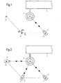
- the arm 1 of a machine tool is shown, as shown by the double arrow indicated, is movable.
- this tool arm is a spherical retroreflector 2 arranged.
- the position of this retroreflector 2 and thus also the corresponding Position of the tool arm is determined by means of a laser tracker 3 become.
- a laser tracker 3 is first determined on a first, with high accuracy Position 4 provided. From this position is by means of the laser tracker 3, i. in particular by means of the laser interferometer of the laser tracker 3, the Distance between the position of the laser tracker and the position of the retroreflector 2 determined.
- the laser tracker 3 is in each case at the positions 4 '. and 4 ". From each of these positions, the distance between the respective position of the laser tracker and the retroreflector 2 determined.
- the coordinate axes corresponding unit vectors e 1 and e 2 are shown.
- the third coordinate direction (and thus the vector e 3 , possibly with suitable normalization) then results, for example, from the vector product of the vectors e 1 and e 2 lying parallel to the first two coordinate directions.
- FIG. 2 shows an alternative embodiment in which the position coordinates a retroreflector are determined.
- the position coordinates a retroreflector are determined.
- the Points 4 'and 4 each have their own laser tracker 3, 3' and 3" arranged.
- the laser trackers can also follow a movement of the tool arm 1 and thereby determine each changing position.
Landscapes
- Physics & Mathematics (AREA)
- General Physics & Mathematics (AREA)
- Length Measuring Devices By Optical Means (AREA)
Priority Applications (1)
| Application Number | Priority Date | Filing Date | Title |
|---|---|---|---|
| EP03019774A EP1510779A1 (fr) | 2003-08-29 | 2003-08-29 | Procédé pour déterminer des coordonnées de position |
Applications Claiming Priority (1)
| Application Number | Priority Date | Filing Date | Title |
|---|---|---|---|
| EP03019774A EP1510779A1 (fr) | 2003-08-29 | 2003-08-29 | Procédé pour déterminer des coordonnées de position |
Publications (1)
| Publication Number | Publication Date |
|---|---|
| EP1510779A1 true EP1510779A1 (fr) | 2005-03-02 |
Family
ID=34089647
Family Applications (1)
| Application Number | Title | Priority Date | Filing Date |
|---|---|---|---|
| EP03019774A Withdrawn EP1510779A1 (fr) | 2003-08-29 | 2003-08-29 | Procédé pour déterminer des coordonnées de position |
Country Status (1)
| Country | Link |
|---|---|
| EP (1) | EP1510779A1 (fr) |
Cited By (5)
| Publication number | Priority date | Publication date | Assignee | Title |
|---|---|---|---|---|
| CN100370220C (zh) * | 2005-10-19 | 2008-02-20 | 浙江工业大学 | 结构光三维系统相对参数的单图像自定标方法 |
| DE102010032467A1 (de) * | 2010-07-28 | 2012-02-02 | Carl Zeiss Ag | Messsystem zum Vermessen von ortsfest positionierten Messobjekten |
| WO2014139487A1 (fr) * | 2013-03-11 | 2014-09-18 | CVUT v Praze, Fakulta strojní | Procédé et appareil pour mesure optique redondante et/ou étalonnage de position d'objet dans l'espace |
| WO2017102225A1 (fr) * | 2015-12-17 | 2017-06-22 | Endress+Hauser Gmbh+Co. Kg | Système d'étalonnage permettant d'étalonner au moins un instrument de mesure de distance |
| CH714502A1 (fr) * | 2017-12-22 | 2019-06-28 | Watch Out Sa | Système optique pour la mesure tridimensionnelle, dispositif et procédé de mesure avec un tel système optique. |
Citations (3)
| Publication number | Priority date | Publication date | Assignee | Title |
|---|---|---|---|---|
| US4621926A (en) * | 1985-04-30 | 1986-11-11 | Lasercon Corporation | Interferometer system for controlling non-rectilinear movement of an object |
| WO1988007656A1 (fr) * | 1987-03-21 | 1988-10-06 | Renishaw Plc | Systeme a interferometres de detection de position |
| US4932131A (en) * | 1987-03-06 | 1990-06-12 | Renishaw Plc | Position determination apparatus |
-
2003
- 2003-08-29 EP EP03019774A patent/EP1510779A1/fr not_active Withdrawn
Patent Citations (3)
| Publication number | Priority date | Publication date | Assignee | Title |
|---|---|---|---|---|
| US4621926A (en) * | 1985-04-30 | 1986-11-11 | Lasercon Corporation | Interferometer system for controlling non-rectilinear movement of an object |
| US4932131A (en) * | 1987-03-06 | 1990-06-12 | Renishaw Plc | Position determination apparatus |
| WO1988007656A1 (fr) * | 1987-03-21 | 1988-10-06 | Renishaw Plc | Systeme a interferometres de detection de position |
Non-Patent Citations (2)
| Title |
|---|
| LAU K ET AL: "ROBOT PERFORMANCE MEASUREMENTS USING AUTOMATIC LASER TRACKING TECHNIQUES", ROBOTICS AND COMPUTER INTEGRATED MANUFACTURING, PERGAMON PRESS, OXFORD, GB, vol. 2, no. 3/4, 1985, pages 227 - 236, XP002035850, ISSN: 0736-5845 * |
| NAKAMURA O ET AL: "A LASER TRACKING ROBOT-PERFORMANCE CALIBRATION SYSTEM USING BALL- SEATED BEARING MECHANISMS AND A SPHERICALLY SHAPED CAT'S-EYE RETROREFLECTOR", REVIEW OF SCIENTIFIC INSTRUMENTS, AMERICAN INSTITUTE OF PHYSICS. NEW YORK, US, vol. 65, no. 4, PART 1, 1 April 1994 (1994-04-01), pages 1006 - 1011, XP000447697, ISSN: 0034-6748 * |
Cited By (7)
| Publication number | Priority date | Publication date | Assignee | Title |
|---|---|---|---|---|
| CN100370220C (zh) * | 2005-10-19 | 2008-02-20 | 浙江工业大学 | 结构光三维系统相对参数的单图像自定标方法 |
| DE102010032467A1 (de) * | 2010-07-28 | 2012-02-02 | Carl Zeiss Ag | Messsystem zum Vermessen von ortsfest positionierten Messobjekten |
| WO2014139487A1 (fr) * | 2013-03-11 | 2014-09-18 | CVUT v Praze, Fakulta strojní | Procédé et appareil pour mesure optique redondante et/ou étalonnage de position d'objet dans l'espace |
| WO2017102225A1 (fr) * | 2015-12-17 | 2017-06-22 | Endress+Hauser Gmbh+Co. Kg | Système d'étalonnage permettant d'étalonner au moins un instrument de mesure de distance |
| CN108463696A (zh) * | 2015-12-17 | 2018-08-28 | 恩德莱斯和豪瑟尔欧洲两合公司 | 用于校准至少一个测距装置的校准系统 |
| US10809377B2 (en) | 2015-12-17 | 2020-10-20 | Endress+Hauser SE+Co. KG | Calibrating system for calibrating at least one distance-measuring device |
| CH714502A1 (fr) * | 2017-12-22 | 2019-06-28 | Watch Out Sa | Système optique pour la mesure tridimensionnelle, dispositif et procédé de mesure avec un tel système optique. |
Similar Documents
| Publication | Publication Date | Title |
|---|---|---|
| EP0317967B1 (fr) | Dispositif permettant la déflection-rotation du palpeur de machines de mesure de coordonnées | |
| DE112006001423B4 (de) | Koordinatenmessgerät sowie Verfahren zum Messen eines Objektes mit einem Koordinatenmessgerät | |
| DE3911307C2 (de) | Verfahren zum Feststellen, ob zwei hintereinander angeordnete Wellen hinsichtlich ihrer Mittelachse fluchten oder versetzt sind | |
| EP2093537B1 (fr) | Système et procédé pour déterminer l'alignement de deux pièces de machine rotatives | |
| DE102018105877B3 (de) | Vorrichtung für die Bestimmung einer Ausrichtung einer optischen Vorrichtung eines Kohärenztomographen, Kohärenztomograph und Laserbearbeitungssystem | |
| WO2006042504A1 (fr) | Procédé et système de synchronisation d'angles | |
| DE102007004934B4 (de) | Prüfverfahren für positionierende Maschinen | |
| DE10118392A1 (de) | System und Verfahren zum Bestimmen einer Position oder/und Orientierung zweier Objekte relativ zueinander sowie Strahlführungsanordnung, Interferometeranordnung und Vorrichtung zum Ändern einer optischen Weglänge zum Einsatz in einem solchen System und Verfahren | |
| DE102012205599A1 (de) | Reduzieren von Fehlern einer Drehvorrichtung bei der Bestimmung von Koordinaten eines Werkstücks oder bei der Bearbeitung eines Werkstücks | |
| EP1724549A2 (fr) | Procédé destiné à la détermination des coordonnées en 3D de la surface d'un objet | |
| DE3226005A1 (de) | System zum messen der kontur einer dreidimensionalen oberflaeche, insbesondere eines optischen gegenstandes | |
| DE10339194B4 (de) | Verfahren zur Ermittlung systematischer geometrischer Abweichungen in technischen Mehrkörpersystemen | |
| EP3418680B1 (fr) | Système et procédé de mesure de positionnement | |
| EP0703430A2 (fr) | Procédé de calibration d'une machine de mesure de coördonnées à deux axes de rotation | |
| DE102011012611A1 (de) | Verfahren und Vorrichtung zur berührungslosen Messung eines Winkels | |
| DE10126753A1 (de) | Verfahren zur Genauigkeitssteigerung von Koordinatenmessgeräten und Werkzeugmaschinen | |
| EP0593067B1 (fr) | Dispositif et procédé pour la détermination de l'orientation et la position d'objets à l'aide de rayons lasers | |
| DE3205362C2 (fr) | ||
| DE10048096A1 (de) | Verfahren zur Kalibrierung eines messenden Sensors auf einem Koordinatenmeßgerät | |
| EP1510779A1 (fr) | Procédé pour déterminer des coordonnées de position | |
| DE3614122C2 (fr) | ||
| WO2000049365A1 (fr) | Procede de mesure laser destine a determiner l'azimut, l'elevation et l'ecart de deux broches d'outil par rapport a un plan de reference | |
| DE102010032467A1 (de) | Messsystem zum Vermessen von ortsfest positionierten Messobjekten | |
| DD141061A1 (de) | Einrichtung zum bestimmen der lage und abmessungen von gegenstaenden | |
| DE10319711B4 (de) | Verfahren zur hochgenauen dimensionalen Messung an Messobjekten |
Legal Events
| Date | Code | Title | Description |
|---|---|---|---|
| PUAI | Public reference made under article 153(3) epc to a published international application that has entered the european phase |
Free format text: ORIGINAL CODE: 0009012 |
|
| AK | Designated contracting states |
Kind code of ref document: A1 Designated state(s): AT BE BG CH CY CZ DE DK EE ES FI FR GB GR HU IE IT LI LU MC NL PT RO SE SI SK TR |
|
| AX | Request for extension of the european patent |
Extension state: AL LT LV MK |
|
| 17P | Request for examination filed |
Effective date: 20050902 |
|
| AKX | Designation fees paid |
Designated state(s): AT BE BG CH CY CZ DE DK EE ES FI FR GB GR HU IE IT LI LU MC NL PT RO SE SI SK TR |
|
| STAA | Information on the status of an ep patent application or granted ep patent |
Free format text: STATUS: THE APPLICATION IS DEEMED TO BE WITHDRAWN |
|
| 18D | Application deemed to be withdrawn |
Effective date: 20070301 |