EP1510719A1 - Flugzeugbremseinheit - Google Patents
Flugzeugbremseinheit Download PDFInfo
- Publication number
- EP1510719A1 EP1510719A1 EP04291907A EP04291907A EP1510719A1 EP 1510719 A1 EP1510719 A1 EP 1510719A1 EP 04291907 A EP04291907 A EP 04291907A EP 04291907 A EP04291907 A EP 04291907A EP 1510719 A1 EP1510719 A1 EP 1510719A1
- Authority
- EP
- European Patent Office
- Prior art keywords
- assembly
- piece
- axle
- disks
- crown
- Prior art date
- Legal status (The legal status is an assumption and is not a legal conclusion. Google has not performed a legal analysis and makes no representation as to the accuracy of the status listed.)
- Granted
Links
- 210000005069 ears Anatomy 0.000 claims description 7
- 239000000463 material Substances 0.000 claims description 3
- 239000012190 activator Substances 0.000 abstract 1
- 230000014759 maintenance of location Effects 0.000 abstract 1
- 238000012423 maintenance Methods 0.000 description 4
- 230000000712 assembly Effects 0.000 description 3
- 238000000429 assembly Methods 0.000 description 3
- 230000002093 peripheral effect Effects 0.000 description 3
- 230000000295 complement effect Effects 0.000 description 2
- 238000000034 method Methods 0.000 description 2
- 238000006467 substitution reaction Methods 0.000 description 2
- OKTJSMMVPCPJKN-UHFFFAOYSA-N Carbon Chemical compound [C] OKTJSMMVPCPJKN-UHFFFAOYSA-N 0.000 description 1
- 229920000049 Carbon (fiber) Polymers 0.000 description 1
- 229910000831 Steel Inorganic materials 0.000 description 1
- 229910052799 carbon Inorganic materials 0.000 description 1
- 239000004917 carbon fiber Substances 0.000 description 1
- 230000008878 coupling Effects 0.000 description 1
- 238000010168 coupling process Methods 0.000 description 1
- 238000005859 coupling reaction Methods 0.000 description 1
- 238000012217 deletion Methods 0.000 description 1
- 230000037430 deletion Effects 0.000 description 1
- 238000011065 in-situ storage Methods 0.000 description 1
- 230000010354 integration Effects 0.000 description 1
- VNWKTOKETHGBQD-UHFFFAOYSA-N methane Chemical compound C VNWKTOKETHGBQD-UHFFFAOYSA-N 0.000 description 1
- 238000011084 recovery Methods 0.000 description 1
- 239000010959 steel Substances 0.000 description 1
Images
Classifications
-
- F—MECHANICAL ENGINEERING; LIGHTING; HEATING; WEAPONS; BLASTING
- F16—ENGINEERING ELEMENTS AND UNITS; GENERAL MEASURES FOR PRODUCING AND MAINTAINING EFFECTIVE FUNCTIONING OF MACHINES OR INSTALLATIONS; THERMAL INSULATION IN GENERAL
- F16D—COUPLINGS FOR TRANSMITTING ROTATION; CLUTCHES; BRAKES
- F16D55/00—Brakes with substantially-radial braking surfaces pressed together in axial direction, e.g. disc brakes
- F16D55/24—Brakes with substantially-radial braking surfaces pressed together in axial direction, e.g. disc brakes with a plurality of axially-movable discs, lamellae, or pads, pressed from one side towards an axially-located member
- F16D55/26—Brakes with substantially-radial braking surfaces pressed together in axial direction, e.g. disc brakes with a plurality of axially-movable discs, lamellae, or pads, pressed from one side towards an axially-located member without self-tightening action
- F16D55/36—Brakes with a plurality of rotating discs all lying side by side
-
- F—MECHANICAL ENGINEERING; LIGHTING; HEATING; WEAPONS; BLASTING
- F16—ENGINEERING ELEMENTS AND UNITS; GENERAL MEASURES FOR PRODUCING AND MAINTAINING EFFECTIVE FUNCTIONING OF MACHINES OR INSTALLATIONS; THERMAL INSULATION IN GENERAL
- F16D—COUPLINGS FOR TRANSMITTING ROTATION; CLUTCHES; BRAKES
- F16D55/00—Brakes with substantially-radial braking surfaces pressed together in axial direction, e.g. disc brakes
- F16D2055/0075—Constructional features of axially engaged brakes
- F16D2055/0091—Plural actuators arranged side by side on the same side of the rotor
-
- F—MECHANICAL ENGINEERING; LIGHTING; HEATING; WEAPONS; BLASTING
- F16—ENGINEERING ELEMENTS AND UNITS; GENERAL MEASURES FOR PRODUCING AND MAINTAINING EFFECTIVE FUNCTIONING OF MACHINES OR INSTALLATIONS; THERMAL INSULATION IN GENERAL
- F16D—COUPLINGS FOR TRANSMITTING ROTATION; CLUTCHES; BRAKES
- F16D2121/00—Type of actuator operation force
- F16D2121/18—Electric or magnetic
- F16D2121/24—Electric or magnetic using motors
-
- F—MECHANICAL ENGINEERING; LIGHTING; HEATING; WEAPONS; BLASTING
- F16—ENGINEERING ELEMENTS AND UNITS; GENERAL MEASURES FOR PRODUCING AND MAINTAINING EFFECTIVE FUNCTIONING OF MACHINES OR INSTALLATIONS; THERMAL INSULATION IN GENERAL
- F16D—COUPLINGS FOR TRANSMITTING ROTATION; CLUTCHES; BRAKES
- F16D2250/00—Manufacturing; Assembly
- F16D2250/0084—Assembly or disassembly
Definitions
- the present invention relates to the field of braking of aircraft, and more particularly a set braking system of the type comprising a battery of discs axially surrounding a wheel axle.
- Conventional type aircraft braking assemblies have a stack of disks surrounding coaxially a wheel axle, said stack being composed alternately rotating rotors disks with the wheel and disks stators linked in rotation with a torsion tube.
- the stack of discs is pressed between a rear retaining piece and the pushers of a plurality actuators arranged circumferentially on a supporting front crown, in accordance with the preamble of claim 1.
- actuators were used hydraulic, which were fixed on a crown said hydraulic on which was mounted the different associated pipelines.
- the braking assemblies were then consisting of three sets, namely a heat sink consisting of the stack of disks, a torsion tube and an associated retaining back piece, and a crown hydraulic. In this case, for any repair work or maintenance on the braking assembly, one used to systematically file the three aforementioned assemblies, so that they can be dismantled and the necessary interventions.
- the present invention aims to conceive an aircraft braking system that does not have the disadvantages mentioned above, and in particular allowing removing a stack of disks as part of an operation maintenance with a minimum of disassembly.
- Another object of the invention is to provide a braking assembly whose structure allows to lower significantly the weight compared to previous achievements above.
- an aircraft braking system having a stack of disks coaxially surrounding a wheel axle, said stack being composed alternately of rotors discs linked in rotation with the wheel and stator disks linked in rotation with a torsion tube, and being pressed between a back piece of restraint and the pushers of a plurality of electromechanical actuators arranged circumferentially on a crown front support, the torsion tube and the supporting crown electro-mechanical actuators constituting a monobloc assembly which is fixed on the axle, and the workpiece rear restraint being removably attached to said one-piece assembly at the end thereof.
- the one-piece assembly forming a crown and torsion tube has a unitary flange (that is, from one piece with the monobloc assembly) to connection level between crown and torsion tube, said flange extending in a plane perpendicular to the axis of said assembly and being fixed on a collar protruding from the axle.
- the crown portion of the one-piece assembly includes a plurality radially protruding ears, each ear supporting an electromechanical actuator.
- each electro-mechanical actuator comprises a housing housing a screw-nut system associated with the drive of the pusher said actuator, and an electric motor associated therewith housing, said housing through the corresponding ear on which it is directly attached.
- each electro-mechanical actuator extends in a circumferential direction, and motor is also attached to the crown part by a associated appendix of it arranged between two ears adjacent.
- the monobloc assembly forming crown and torsion tube is made in the same material.
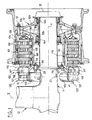
- Figure 1 makes it possible to distinguish a structure classic undercarriage with a rod basically vertical axis Z bottom ending two axles of horizontal axis X, of which only one is visible here.
- the axle 11 carries a wheel 12, here realized in the form of two contiguous components 12a, 12b, which are joined to each other by bolting means 13.
- the wheel 12 rests by means of bearings 14a, 14b on the end of the axle 11.
- the part hollow end of the axle 11 usually houses devices associated with a tachometer generation for the measuring the speed of the wheel, which devices not represented here. We only figured, in lines mixed, the closing cowling 15 which is fixed on the wheel 12.
- This braking assembly has a stack of disks 101 surrounding coaxially the wheel axle 11.
- the disk stack 101 is composed alternately of rotor disks 102 which are rotatably connected with the wheel 12 and stator disks 103 which are connected in rotation with a tubular element 111 called a torsion tube.
- the wheel 12 is equipped with bars axial 104 which pass into peripheral notches rotor disks 102, which ensures the rotational coupling between said disks and the wheel 12.
- the tubular element torsion tube 111 presents the same way of the axial bars 105 which pass in notches peripherals of stator disks 103.
- Disks 102, 103 of the disk stack 101 are made of carbon fiber. The number of discs illustrated here naturally does not constitute an example, but in all cases the disks forming the two ends of the disk stack are disks integral with the torsion tube, that is to say that they are stator disks.
- the disk stack 101 is arranged between a retaining back piece 106 and a set of actuators electro-mechanical 120 which are arranged circumferentially on a front crown of support.
- the back room retainer 106 is constituted by a plate annular 107 equipped with pins 109 for fixing a rear plate 108. Alternatively, it can be provided point-skip retaining systems distributed over the circumference of the back restraint.
- Each electro-mechanical actuator 120 has a pusher 122, so that the disk stack 101 can be pressed between the rear retaining piece 106 and the pushers 122 of the electro-mechanical actuators 120 arranged circumferentially on the front crown of support noted 112.
- the torsion tube 111 and the ring 112 supporting the electro-mechanical actuators 120 constitute a monobloc assembly noted 110 which is fixed on the axle 11, and the rear retaining piece 106 is fixed removably on said monobloc assembly 110 in end of it.
- Fixing the rear retaining piece 106 on the one-piece assembly 110 is provided by means of bolting 113, arranged here at the level of the axial bars keying 105.
- the one-piece assembly 110 forming a crown 112 and torsion tube 111 has a unitary flange 114 at the connection between crown and torsion tube, said flange extending in a plane perpendicular to the X axis and being removably attached on a protruding collar 20 of the axle 11.
- the attachment of the monobloc assembly 110 to the axle 11 is provided by bolting means 115 passing through the associated openings of the flange 20 of the axle 11 and the unitary flange 114 of the assembly monobloc 110.
- centering pins 116 guaranteeing the perfect angular setting of the monobloc assembly 110 relative to the axle 11.
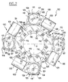
- part crown of the one-piece assembly 110 which provides support electro-mechanical actuators 120.
- the crown portion 112 of the monoblock assembly 110 comprises a plurality of ears 117, here four in number, which extend radially protruding, each ear supporting an electromechanical actuator 120.
- the 117 ears of the party ring 112 of the monobloc assembly 110 extend in a plane perpendicular to the X axis, which is in this case offset forward with respect to the plane of the flange 114 fixing said assembly. This offset allows a better integration of electro-mechanical actuators 120, and in particular their electric motor.
- each electromechanical actuator 120 comprises a housing 121 housing a screw-nut system (not visible in the figures) which is associated with driving the pusher 122 of said actuator, and a 123 electric motor associated with this housing, being here fixed to said housing cantilever (we can naturally provide other actuator structures, with a motor surrounding the screw-nut system).
- Each case 121 housing a screw-nut drive system of the pusher has a central axis X1 which is parallel to the X axis of the axle 11.
- the electric motor 123 of each actuator electromechanical 120 for the arrangement presently illustrated, extends in a circumferential direction Z1.
- the housing 121 has four peripheral appendages 124 allowing fixation by bolts 125 on the ear concerned 117. It should be noted that the housing 121 goes through the corresponding ear 117 on which it is directly attached, passing through a opening 118 of said ear, as well as this is better visible in Figure 1.
- FIG 1 there is further illustrated a screen 119 disposed at the level of the pushers 122 of the different electromechanical actuators 120. This screen helps protect the associated drive systems pushers 122 of the actuators.
- the monobloc assembly 110 forming crown 112 and torsion tube 111 will be realized in the same material, for example steel.
- the invention is not limited to the number electromechanical actuators or the structure of these, and we can provide as a variant a different number of actuators and / or a different mounting arrangement on the crown portion of the monoblock assembly 110.
Landscapes
- Engineering & Computer Science (AREA)
- General Engineering & Computer Science (AREA)
- Mechanical Engineering (AREA)
- Braking Arrangements (AREA)
Applications Claiming Priority (2)
| Application Number | Priority Date | Filing Date | Title |
|---|---|---|---|
| FR0310246A FR2859259B1 (fr) | 2003-08-28 | 2003-08-28 | Ensemble de freinage d'aeronef |
| FR0310246 | 2003-08-28 |
Publications (2)
| Publication Number | Publication Date |
|---|---|
| EP1510719A1 true EP1510719A1 (de) | 2005-03-02 |
| EP1510719B1 EP1510719B1 (de) | 2008-04-16 |
Family
ID=34089866
Family Applications (1)
| Application Number | Title | Priority Date | Filing Date |
|---|---|---|---|
| EP04291907A Expired - Lifetime EP1510719B1 (de) | 2003-08-28 | 2004-07-27 | Flugzeugbremseinheit |
Country Status (8)
| Country | Link |
|---|---|
| US (1) | US20050056499A1 (de) |
| EP (1) | EP1510719B1 (de) |
| AT (1) | ATE392565T1 (de) |
| BR (1) | BRPI0403306B1 (de) |
| CA (1) | CA2478879C (de) |
| DE (1) | DE602004013093T2 (de) |
| ES (1) | ES2304155T3 (de) |
| FR (1) | FR2859259B1 (de) |
Cited By (5)
| Publication number | Priority date | Publication date | Assignee | Title |
|---|---|---|---|---|
| EP2000692A1 (de) * | 2007-06-05 | 2008-12-10 | Messier-Bugatti | An eine konische Achse angepasste Bremse |
| FR3037563A1 (fr) * | 2015-06-16 | 2016-12-23 | Messier Bugatti Dowty | Procede de maintenance d'un frein d'aeronef. |
| EP3473880A1 (de) * | 2017-10-20 | 2019-04-24 | Goodrich Corporation | Drehmomentplattenzylinder mit gemischtem zylinderstützsockel |
| US11753185B2 (en) | 2019-04-23 | 2023-09-12 | Airbus Operations Limited | Aircraft braking system |
| FR3145549A1 (fr) * | 2023-02-08 | 2024-08-09 | Safran Landing Systems | Dispositif de freinage d’une roue d’aéronef |
Families Citing this family (9)
| Publication number | Priority date | Publication date | Assignee | Title |
|---|---|---|---|---|
| FR2862280B1 (fr) * | 2003-11-14 | 2006-03-03 | Messier Bugatti | Atterrisseur, frein pour roue d'aeronef, ensemble de roue freinee d'aeronef, et procede de maintenance d'un tel atterrisseur |
| US7228945B2 (en) * | 2005-03-16 | 2007-06-12 | Hr Textron, Inc. | Techniques for employing electric brakes to control movement of rotatable components |
| GB201001176D0 (en) * | 2010-01-26 | 2010-03-10 | Airbus Operations Ltd | Aircraft braking actuator |
| GB201001175D0 (en) * | 2010-01-26 | 2010-03-10 | Airbus Operations Ltd | Aircraft steering actuator |
| FR2970698B1 (fr) * | 2011-01-21 | 2013-10-04 | Messier Dowty Sa | Dispositif de freinage et d'entrainement en rotation d'une roue d'aeronef |
| FR3026717B1 (fr) * | 2014-10-03 | 2016-11-25 | Messier Bugatti Dowty | Atterrisseur d'aeronef. |
| US9995353B2 (en) * | 2015-12-21 | 2018-06-12 | Goodrich Corporation | Modified actuator design to improve load distribution and damping |
| CN107878737A (zh) * | 2017-12-01 | 2018-04-06 | 北京北摩高科摩擦材料股份有限公司 | 一种飞机刹车机轮 |
| FR3109765B1 (fr) * | 2020-05-04 | 2022-06-17 | Safran Landing Systems | Ecran thermique pour dispositif de freinage d’une roue d’aéronef |
Citations (11)
| Publication number | Priority date | Publication date | Assignee | Title |
|---|---|---|---|---|
| GB1302216A (de) | 1969-04-07 | 1973-01-04 | Goodrich Co B F | |
| US3887041A (en) | 1972-12-19 | 1975-06-03 | Dunlop Ltd | Disc brakes |
| US4742895A (en) | 1984-07-02 | 1988-05-10 | The B. F. Goodrich Company | Disk brake assembly |
| US5494138A (en) | 1994-10-14 | 1996-02-27 | Alliedsignal, Inc. | Aircraft brake torque transfer assembly |
| US5509507A (en) | 1989-06-01 | 1996-04-23 | Dunlop Limited A British Company | Multi-disc brakes |
| US5558186A (en) | 1995-05-24 | 1996-09-24 | The Bfgoodrich Company | Friction disk with renewable wear faces |
| US5862890A (en) | 1996-01-16 | 1999-01-26 | Mcdonnell Douglas Corporation | Restrained aircraft brake apparatus |
| EP0936373A2 (de) * | 1998-02-13 | 1999-08-18 | The BFGoodrich Company | Flugzeugbremse mit elektromechanischen Betätigungsmodulen sowie Methode zu deren Wartung |
| US5944147A (en) | 1996-06-28 | 1999-08-31 | Alliedsignal Inc. | Integrated aircraft wheel, brake and axle |
| US5992577A (en) | 1996-10-31 | 1999-11-30 | Messier-Bugatti | Arrangement of carbon brake disks for an aircraft brake unit and a method of assembling disks in such an arrangement |
| WO2001020188A1 (en) | 1999-09-13 | 2001-03-22 | The B.F.Goodrich Company | Electric brake actuator module for aircraft |
Family Cites Families (9)
| Publication number | Priority date | Publication date | Assignee | Title |
|---|---|---|---|---|
| US2934174A (en) * | 1957-07-09 | 1960-04-26 | Sarl Rech S Etudes Production | Multi-disc brake |
| FR1523402A (fr) * | 1967-03-22 | 1968-05-03 | Hispano Suiza Lallemant Soc | Perfectionnements apportés aux freins à disques multiples, notamment pour roues d'aviation |
| GB1220351A (en) * | 1967-05-18 | 1971-01-27 | Dunlop Co Ltd | Improvements in disc brakes |
| GB1446312A (en) * | 1972-12-21 | 1976-08-18 | Dunlop Ltd | Disc brakes |
| US3977631A (en) * | 1975-06-04 | 1976-08-31 | The Boeing Company | Aircraft wheel drive apparatus and method |
| FR2668440B1 (fr) * | 1990-10-30 | 1992-12-24 | Alsthom Gec | Systeme de freinage pour vehicule ferroviaire. |
| US5321876A (en) * | 1992-12-10 | 1994-06-21 | Allied-Signal Inc. | Method of converting aircraft brake assemblies |
| US6003640A (en) * | 1997-05-09 | 1999-12-21 | The B.F. Goodrich Company | Electronic braking system with brake wear measurement and running clearance adjustment |
| US6581730B1 (en) * | 1999-09-13 | 2003-06-24 | Goodrich Corporation | Aircraft landing gear with integrated brake actuation system |
-
2003
- 2003-08-28 FR FR0310246A patent/FR2859259B1/fr not_active Expired - Lifetime
-
2004
- 2004-07-27 EP EP04291907A patent/EP1510719B1/de not_active Expired - Lifetime
- 2004-07-27 DE DE602004013093T patent/DE602004013093T2/de not_active Expired - Lifetime
- 2004-07-27 ES ES04291907T patent/ES2304155T3/es not_active Expired - Lifetime
- 2004-07-27 AT AT04291907T patent/ATE392565T1/de not_active IP Right Cessation
- 2004-08-10 US US10/914,126 patent/US20050056499A1/en not_active Abandoned
- 2004-08-18 BR BRPI0403306-0A patent/BRPI0403306B1/pt not_active IP Right Cessation
- 2004-08-25 CA CA002478879A patent/CA2478879C/fr not_active Expired - Lifetime
Patent Citations (11)
| Publication number | Priority date | Publication date | Assignee | Title |
|---|---|---|---|---|
| GB1302216A (de) | 1969-04-07 | 1973-01-04 | Goodrich Co B F | |
| US3887041A (en) | 1972-12-19 | 1975-06-03 | Dunlop Ltd | Disc brakes |
| US4742895A (en) | 1984-07-02 | 1988-05-10 | The B. F. Goodrich Company | Disk brake assembly |
| US5509507A (en) | 1989-06-01 | 1996-04-23 | Dunlop Limited A British Company | Multi-disc brakes |
| US5494138A (en) | 1994-10-14 | 1996-02-27 | Alliedsignal, Inc. | Aircraft brake torque transfer assembly |
| US5558186A (en) | 1995-05-24 | 1996-09-24 | The Bfgoodrich Company | Friction disk with renewable wear faces |
| US5862890A (en) | 1996-01-16 | 1999-01-26 | Mcdonnell Douglas Corporation | Restrained aircraft brake apparatus |
| US5944147A (en) | 1996-06-28 | 1999-08-31 | Alliedsignal Inc. | Integrated aircraft wheel, brake and axle |
| US5992577A (en) | 1996-10-31 | 1999-11-30 | Messier-Bugatti | Arrangement of carbon brake disks for an aircraft brake unit and a method of assembling disks in such an arrangement |
| EP0936373A2 (de) * | 1998-02-13 | 1999-08-18 | The BFGoodrich Company | Flugzeugbremse mit elektromechanischen Betätigungsmodulen sowie Methode zu deren Wartung |
| WO2001020188A1 (en) | 1999-09-13 | 2001-03-22 | The B.F.Goodrich Company | Electric brake actuator module for aircraft |
Cited By (8)
| Publication number | Priority date | Publication date | Assignee | Title |
|---|---|---|---|---|
| EP2000692A1 (de) * | 2007-06-05 | 2008-12-10 | Messier-Bugatti | An eine konische Achse angepasste Bremse |
| FR2917064A1 (fr) * | 2007-06-05 | 2008-12-12 | Messier Bugatti Sa | Frein adapte a un essieu conique |
| US7866448B2 (en) | 2007-06-05 | 2011-01-11 | Messier-Bugatti | Aircraft brake particularly adapted for mounting on a conical axle |
| FR3037563A1 (fr) * | 2015-06-16 | 2016-12-23 | Messier Bugatti Dowty | Procede de maintenance d'un frein d'aeronef. |
| EP3473880A1 (de) * | 2017-10-20 | 2019-04-24 | Goodrich Corporation | Drehmomentplattenzylinder mit gemischtem zylinderstützsockel |
| US11753185B2 (en) | 2019-04-23 | 2023-09-12 | Airbus Operations Limited | Aircraft braking system |
| FR3145549A1 (fr) * | 2023-02-08 | 2024-08-09 | Safran Landing Systems | Dispositif de freinage d’une roue d’aéronef |
| WO2024165464A1 (fr) * | 2023-02-08 | 2024-08-15 | Safran Landing Systems | Dispositif de freinage d'une roue d'aeronef |
Also Published As
| Publication number | Publication date |
|---|---|
| US20050056499A1 (en) | 2005-03-17 |
| FR2859259B1 (fr) | 2006-02-03 |
| ES2304155T3 (es) | 2008-09-16 |
| FR2859259A1 (fr) | 2005-03-04 |
| CA2478879C (fr) | 2008-10-07 |
| EP1510719B1 (de) | 2008-04-16 |
| ATE392565T1 (de) | 2008-05-15 |
| DE602004013093T2 (de) | 2009-07-02 |
| BRPI0403306B1 (pt) | 2013-02-05 |
| DE602004013093D1 (de) | 2008-05-29 |
| CA2478879A1 (fr) | 2005-02-28 |
| BRPI0403306A (pt) | 2005-05-31 |
Similar Documents
| Publication | Publication Date | Title |
|---|---|---|
| EP1510719B1 (de) | Flugzeugbremseinheit | |
| EP2361830B1 (de) | Landefahrwerk mit Vorrichtung zum Antrieb vom Fahrwerksrad | |
| CA2649112C (fr) | Atterrisseur, frein pour roue d'aeronef, ensemble de roue freinee d'aeronef, et procede de maintenance d'un tel atterrisseur | |
| EP2876326B1 (de) | Verfahren zur Erneuerung und Verwendung von Bremsscheiben vom Typ rückwärtiger Stator mit Bremsklötzen, montierte Scheibe und entsprechender Scheibenstapel. | |
| FR2553482A1 (fr) | Ensemble rotatif multidisque a elements elastiques d'ecartement deformables, en particulier embrayage, notamment pour vehicule agricole | |
| EP0063993A1 (de) | Lageranordnung, insbesondere für Turbomaschinen | |
| FR2665417A1 (fr) | Agencement d'appareillage rotatif pour trains d'atterrissage. | |
| EP0368759B1 (de) | Rotor für Hammermühle | |
| EP0133389B1 (de) | Scheibenbremse mit abnehmbarem Verstärkungssattelarm | |
| CA1233994A (fr) | Moyeu de roue a reducteur integre | |
| FR2470299A1 (fr) | Support annulaire pour garnitures de friction, notamment pour freins a disque | |
| FR3016009A1 (fr) | Dispositif de frein a tambour adaptable pour inclure un frein de stationnement traditionnel ou fonctionnant en mode duo servo | |
| FR3062699A1 (fr) | Support d' embrayage | |
| EP2000693B1 (de) | Anordnung aus Rad und Bremse eines Luftschiffs | |
| EP0425338B1 (de) | Getriebe für Fahrzeuge mit elektrischer Bremsvorrichtung | |
| WO2001042645A1 (fr) | Procede d'assemblage d'une roue de turbine de type pelton | |
| EP0019542A1 (de) | Hammermühlen mit angelenkten Schlägern | |
| EP0366563B1 (de) | Selbstsperrendes Differential | |
| EP0683867A1 (de) | Kupplungseinheit mittels lüftungsflügeln am schwungrad gehalten | |
| EP0789442B1 (de) | Fahrzeuggetriebe versehen mit einem elektrischen Retarder | |
| FR2649049A1 (fr) | Perfectionnements aux transmissions de vehicules equipees de ralentisseurs electriques | |
| FR2844317A1 (fr) | Embrayage a friction | |
| FR2732087A1 (fr) | Perfectionnements aux differentiels autobloquants | |
| FR2634401A1 (fr) | Rotor equipe de boucliers de protection, destine a un concasseur | |
| FR3123097A1 (fr) | Porte-disque assemblé et double embrayage humide comprenant ce porte-disque assemblé |
Legal Events
| Date | Code | Title | Description |
|---|---|---|---|
| PUAI | Public reference made under article 153(3) epc to a published international application that has entered the european phase |
Free format text: ORIGINAL CODE: 0009012 |
|
| AK | Designated contracting states |
Kind code of ref document: A1 Designated state(s): AT BE BG CH CY CZ DE DK EE ES FI FR GB GR HU IE IT LI LU MC NL PL PT RO SE SI SK TR |
|
| AX | Request for extension of the european patent |
Extension state: AL HR LT LV MK |
|
| 17P | Request for examination filed |
Effective date: 20050808 |
|
| AKX | Designation fees paid |
Designated state(s): AT BE BG CH CY CZ DE DK EE ES FI FR GB GR HU IE IT LI LU MC NL PL PT RO SE SI SK TR |
|
| GRAP | Despatch of communication of intention to grant a patent |
Free format text: ORIGINAL CODE: EPIDOSNIGR1 |
|
| GRAS | Grant fee paid |
Free format text: ORIGINAL CODE: EPIDOSNIGR3 |
|
| GRAA | (expected) grant |
Free format text: ORIGINAL CODE: 0009210 |
|
| AK | Designated contracting states |
Kind code of ref document: B1 Designated state(s): AT BE BG CH CY CZ DE DK EE ES FI FR GB GR HU IE IT LI LU MC NL PL PT RO SE SI SK TR |
|
| REG | Reference to a national code |
Ref country code: CH Ref legal event code: EP |
|
| REG | Reference to a national code |
Ref country code: IE Ref legal event code: FG4D Free format text: LANGUAGE OF EP DOCUMENT: FRENCH |
|
| REF | Corresponds to: |
Ref document number: 602004013093 Country of ref document: DE Date of ref document: 20080529 Kind code of ref document: P |
|
| REG | Reference to a national code |
Ref country code: ES Ref legal event code: FG2A Ref document number: 2304155 Country of ref document: ES Kind code of ref document: T3 |
|
| PG25 | Lapsed in a contracting state [announced via postgrant information from national office to epo] |
Ref country code: SI Free format text: LAPSE BECAUSE OF FAILURE TO SUBMIT A TRANSLATION OF THE DESCRIPTION OR TO PAY THE FEE WITHIN THE PRESCRIBED TIME-LIMIT Effective date: 20080416 |
|
| NLV1 | Nl: lapsed or annulled due to failure to fulfill the requirements of art. 29p and 29m of the patents act | ||
| PG25 | Lapsed in a contracting state [announced via postgrant information from national office to epo] |
Ref country code: NL Free format text: LAPSE BECAUSE OF FAILURE TO SUBMIT A TRANSLATION OF THE DESCRIPTION OR TO PAY THE FEE WITHIN THE PRESCRIBED TIME-LIMIT Effective date: 20080416 Ref country code: PT Free format text: LAPSE BECAUSE OF FAILURE TO SUBMIT A TRANSLATION OF THE DESCRIPTION OR TO PAY THE FEE WITHIN THE PRESCRIBED TIME-LIMIT Effective date: 20080916 Ref country code: FI Free format text: LAPSE BECAUSE OF FAILURE TO SUBMIT A TRANSLATION OF THE DESCRIPTION OR TO PAY THE FEE WITHIN THE PRESCRIBED TIME-LIMIT Effective date: 20080416 Ref country code: BG Free format text: LAPSE BECAUSE OF FAILURE TO SUBMIT A TRANSLATION OF THE DESCRIPTION OR TO PAY THE FEE WITHIN THE PRESCRIBED TIME-LIMIT Effective date: 20080716 |
|
| PG25 | Lapsed in a contracting state [announced via postgrant information from national office to epo] |
Ref country code: PL Free format text: LAPSE BECAUSE OF FAILURE TO SUBMIT A TRANSLATION OF THE DESCRIPTION OR TO PAY THE FEE WITHIN THE PRESCRIBED TIME-LIMIT Effective date: 20080416 Ref country code: AT Free format text: LAPSE BECAUSE OF FAILURE TO SUBMIT A TRANSLATION OF THE DESCRIPTION OR TO PAY THE FEE WITHIN THE PRESCRIBED TIME-LIMIT Effective date: 20080416 |
|
| REG | Reference to a national code |
Ref country code: IE Ref legal event code: FD4D |
|
| PG25 | Lapsed in a contracting state [announced via postgrant information from national office to epo] |
Ref country code: IE Free format text: LAPSE BECAUSE OF FAILURE TO SUBMIT A TRANSLATION OF THE DESCRIPTION OR TO PAY THE FEE WITHIN THE PRESCRIBED TIME-LIMIT Effective date: 20080416 Ref country code: SE Free format text: LAPSE BECAUSE OF FAILURE TO SUBMIT A TRANSLATION OF THE DESCRIPTION OR TO PAY THE FEE WITHIN THE PRESCRIBED TIME-LIMIT Effective date: 20080716 Ref country code: CZ Free format text: LAPSE BECAUSE OF FAILURE TO SUBMIT A TRANSLATION OF THE DESCRIPTION OR TO PAY THE FEE WITHIN THE PRESCRIBED TIME-LIMIT Effective date: 20080416 Ref country code: DK Free format text: LAPSE BECAUSE OF FAILURE TO SUBMIT A TRANSLATION OF THE DESCRIPTION OR TO PAY THE FEE WITHIN THE PRESCRIBED TIME-LIMIT Effective date: 20080416 |
|
| PLBE | No opposition filed within time limit |
Free format text: ORIGINAL CODE: 0009261 |
|
| STAA | Information on the status of an ep patent application or granted ep patent |
Free format text: STATUS: NO OPPOSITION FILED WITHIN TIME LIMIT |
|
| PG25 | Lapsed in a contracting state [announced via postgrant information from national office to epo] |
Ref country code: RO Free format text: LAPSE BECAUSE OF FAILURE TO SUBMIT A TRANSLATION OF THE DESCRIPTION OR TO PAY THE FEE WITHIN THE PRESCRIBED TIME-LIMIT Effective date: 20080416 Ref country code: SK Free format text: LAPSE BECAUSE OF FAILURE TO SUBMIT A TRANSLATION OF THE DESCRIPTION OR TO PAY THE FEE WITHIN THE PRESCRIBED TIME-LIMIT Effective date: 20080416 |
|
| REG | Reference to a national code |
Ref country code: CH Ref legal event code: PL |
|
| 26N | No opposition filed |
Effective date: 20090119 |
|
| PG25 | Lapsed in a contracting state [announced via postgrant information from national office to epo] |
Ref country code: MC Free format text: LAPSE BECAUSE OF NON-PAYMENT OF DUE FEES Effective date: 20080731 |
|
| PG25 | Lapsed in a contracting state [announced via postgrant information from national office to epo] |
Ref country code: EE Free format text: LAPSE BECAUSE OF FAILURE TO SUBMIT A TRANSLATION OF THE DESCRIPTION OR TO PAY THE FEE WITHIN THE PRESCRIBED TIME-LIMIT Effective date: 20080416 |
|
| PG25 | Lapsed in a contracting state [announced via postgrant information from national office to epo] |
Ref country code: LI Free format text: LAPSE BECAUSE OF NON-PAYMENT OF DUE FEES Effective date: 20080731 Ref country code: CH Free format text: LAPSE BECAUSE OF NON-PAYMENT OF DUE FEES Effective date: 20080731 |
|
| PG25 | Lapsed in a contracting state [announced via postgrant information from national office to epo] |
Ref country code: CY Free format text: LAPSE BECAUSE OF FAILURE TO SUBMIT A TRANSLATION OF THE DESCRIPTION OR TO PAY THE FEE WITHIN THE PRESCRIBED TIME-LIMIT Effective date: 20080416 |
|
| PG25 | Lapsed in a contracting state [announced via postgrant information from national office to epo] |
Ref country code: HU Free format text: LAPSE BECAUSE OF FAILURE TO SUBMIT A TRANSLATION OF THE DESCRIPTION OR TO PAY THE FEE WITHIN THE PRESCRIBED TIME-LIMIT Effective date: 20081017 Ref country code: LU Free format text: LAPSE BECAUSE OF NON-PAYMENT OF DUE FEES Effective date: 20080727 Ref country code: BE Free format text: LAPSE BECAUSE OF NON-PAYMENT OF DUE FEES Effective date: 20080731 |
|
| PG25 | Lapsed in a contracting state [announced via postgrant information from national office to epo] |
Ref country code: TR Free format text: LAPSE BECAUSE OF FAILURE TO SUBMIT A TRANSLATION OF THE DESCRIPTION OR TO PAY THE FEE WITHIN THE PRESCRIBED TIME-LIMIT Effective date: 20080416 |
|
| PG25 | Lapsed in a contracting state [announced via postgrant information from national office to epo] |
Ref country code: GR Free format text: LAPSE BECAUSE OF FAILURE TO SUBMIT A TRANSLATION OF THE DESCRIPTION OR TO PAY THE FEE WITHIN THE PRESCRIBED TIME-LIMIT Effective date: 20080717 |
|
| REG | Reference to a national code |
Ref country code: FR Ref legal event code: CA Effective date: 20111013 Ref country code: FR Ref legal event code: CD Owner name: MESSIER-BUGATTI-DOWTY, FR Effective date: 20111013 |
|
| PGFP | Annual fee paid to national office [announced via postgrant information from national office to epo] |
Ref country code: ES Payment date: 20130729 Year of fee payment: 10 |
|
| PGFP | Annual fee paid to national office [announced via postgrant information from national office to epo] |
Ref country code: IT Payment date: 20130731 Year of fee payment: 10 |
|
| PG25 | Lapsed in a contracting state [announced via postgrant information from national office to epo] |
Ref country code: IT Free format text: LAPSE BECAUSE OF NON-PAYMENT OF DUE FEES Effective date: 20140727 |
|
| REG | Reference to a national code |
Ref country code: DE Ref legal event code: R082 Ref document number: 602004013093 Country of ref document: DE Representative=s name: SCHAUMBURG & PARTNER PATENTANWAELTE GBR, DE Ref country code: DE Ref legal event code: R082 Ref document number: 602004013093 Country of ref document: DE Representative=s name: SCHAUMBURG UND PARTNER PATENTANWAELTE MBB, DE |
|
| REG | Reference to a national code |
Ref country code: ES Ref legal event code: FD2A Effective date: 20160108 |
|
| PG25 | Lapsed in a contracting state [announced via postgrant information from national office to epo] |
Ref country code: ES Free format text: LAPSE BECAUSE OF NON-PAYMENT OF DUE FEES Effective date: 20140728 |
|
| REG | Reference to a national code |
Ref country code: FR Ref legal event code: PLFP Year of fee payment: 13 |
|
| REG | Reference to a national code |
Ref country code: FR Ref legal event code: CD Owner name: MESSIER BUGATTI DOWTY, FR Effective date: 20170518 |
|
| REG | Reference to a national code |
Ref country code: FR Ref legal event code: PLFP Year of fee payment: 14 |
|
| REG | Reference to a national code |
Ref country code: FR Ref legal event code: PLFP Year of fee payment: 15 |
|
| PGFP | Annual fee paid to national office [announced via postgrant information from national office to epo] |
Ref country code: FR Payment date: 20230621 Year of fee payment: 20 |
|
| PGFP | Annual fee paid to national office [announced via postgrant information from national office to epo] |
Ref country code: GB Payment date: 20230620 Year of fee payment: 20 |
|
| PGFP | Annual fee paid to national office [announced via postgrant information from national office to epo] |
Ref country code: DE Payment date: 20230620 Year of fee payment: 20 |
|
| REG | Reference to a national code |
Ref country code: DE Ref legal event code: R071 Ref document number: 602004013093 Country of ref document: DE |
|
| REG | Reference to a national code |
Ref country code: GB Ref legal event code: PE20 Expiry date: 20240726 |
|
| PG25 | Lapsed in a contracting state [announced via postgrant information from national office to epo] |
Ref country code: GB Free format text: LAPSE BECAUSE OF EXPIRATION OF PROTECTION Effective date: 20240726 |
|
| PG25 | Lapsed in a contracting state [announced via postgrant information from national office to epo] |
Ref country code: GB Free format text: LAPSE BECAUSE OF EXPIRATION OF PROTECTION Effective date: 20240726 |