EP1510711A1 - Constant velocity joint - Google Patents
Constant velocity joint Download PDFInfo
- Publication number
- EP1510711A1 EP1510711A1 EP03757196A EP03757196A EP1510711A1 EP 1510711 A1 EP1510711 A1 EP 1510711A1 EP 03757196 A EP03757196 A EP 03757196A EP 03757196 A EP03757196 A EP 03757196A EP 1510711 A1 EP1510711 A1 EP 1510711A1
- Authority
- EP
- European Patent Office
- Prior art keywords
- portion side
- guide track
- bottom portion
- contact
- joint member
- Prior art date
- Legal status (The legal status is an assumption and is not a legal conclusion. Google has not performed a legal analysis and makes no representation as to the accuracy of the status listed.)
- Withdrawn
Links
Images


Classifications
-
- F—MECHANICAL ENGINEERING; LIGHTING; HEATING; WEAPONS; BLASTING
- F16—ENGINEERING ELEMENTS AND UNITS; GENERAL MEASURES FOR PRODUCING AND MAINTAINING EFFECTIVE FUNCTIONING OF MACHINES OR INSTALLATIONS; THERMAL INSULATION IN GENERAL
- F16D—COUPLINGS FOR TRANSMITTING ROTATION; CLUTCHES; BRAKES
- F16D3/00—Yielding couplings, i.e. with means permitting movement between the connected parts during the drive
- F16D3/16—Universal joints in which flexibility is produced by means of pivots or sliding or rolling connecting parts
- F16D3/20—Universal joints in which flexibility is produced by means of pivots or sliding or rolling connecting parts one coupling part entering a sleeve of the other coupling part and connected thereto by sliding or rolling members
- F16D3/22—Universal joints in which flexibility is produced by means of pivots or sliding or rolling connecting parts one coupling part entering a sleeve of the other coupling part and connected thereto by sliding or rolling members the rolling members being balls, rollers, or the like, guided in grooves or sockets in both coupling parts
- F16D3/223—Universal joints in which flexibility is produced by means of pivots or sliding or rolling connecting parts one coupling part entering a sleeve of the other coupling part and connected thereto by sliding or rolling members the rolling members being balls, rollers, or the like, guided in grooves or sockets in both coupling parts the rolling members being guided in grooves in both coupling parts
- F16D3/224—Universal joints in which flexibility is produced by means of pivots or sliding or rolling connecting parts one coupling part entering a sleeve of the other coupling part and connected thereto by sliding or rolling members the rolling members being balls, rollers, or the like, guided in grooves or sockets in both coupling parts the rolling members being guided in grooves in both coupling parts the groove centre-lines in each coupling part lying on a sphere
-
- F—MECHANICAL ENGINEERING; LIGHTING; HEATING; WEAPONS; BLASTING
- F16—ENGINEERING ELEMENTS AND UNITS; GENERAL MEASURES FOR PRODUCING AND MAINTAINING EFFECTIVE FUNCTIONING OF MACHINES OR INSTALLATIONS; THERMAL INSULATION IN GENERAL
- F16D—COUPLINGS FOR TRANSMITTING ROTATION; CLUTCHES; BRAKES
- F16D3/00—Yielding couplings, i.e. with means permitting movement between the connected parts during the drive
- F16D3/16—Universal joints in which flexibility is produced by means of pivots or sliding or rolling connecting parts
- F16D3/20—Universal joints in which flexibility is produced by means of pivots or sliding or rolling connecting parts one coupling part entering a sleeve of the other coupling part and connected thereto by sliding or rolling members
- F16D3/22—Universal joints in which flexibility is produced by means of pivots or sliding or rolling connecting parts one coupling part entering a sleeve of the other coupling part and connected thereto by sliding or rolling members the rolling members being balls, rollers, or the like, guided in grooves or sockets in both coupling parts
- F16D3/223—Universal joints in which flexibility is produced by means of pivots or sliding or rolling connecting parts one coupling part entering a sleeve of the other coupling part and connected thereto by sliding or rolling members the rolling members being balls, rollers, or the like, guided in grooves or sockets in both coupling parts the rolling members being guided in grooves in both coupling parts
- F16D3/2237—Universal joints in which flexibility is produced by means of pivots or sliding or rolling connecting parts one coupling part entering a sleeve of the other coupling part and connected thereto by sliding or rolling members the rolling members being balls, rollers, or the like, guided in grooves or sockets in both coupling parts the rolling members being guided in grooves in both coupling parts where the grooves are composed of radii and adjoining straight lines, i.e. undercut free [UF] type joints
-
- F—MECHANICAL ENGINEERING; LIGHTING; HEATING; WEAPONS; BLASTING
- F16—ENGINEERING ELEMENTS AND UNITS; GENERAL MEASURES FOR PRODUCING AND MAINTAINING EFFECTIVE FUNCTIONING OF MACHINES OR INSTALLATIONS; THERMAL INSULATION IN GENERAL
- F16D—COUPLINGS FOR TRANSMITTING ROTATION; CLUTCHES; BRAKES
- F16D3/00—Yielding couplings, i.e. with means permitting movement between the connected parts during the drive
- F16D3/16—Universal joints in which flexibility is produced by means of pivots or sliding or rolling connecting parts
- F16D3/20—Universal joints in which flexibility is produced by means of pivots or sliding or rolling connecting parts one coupling part entering a sleeve of the other coupling part and connected thereto by sliding or rolling members
- F16D3/22—Universal joints in which flexibility is produced by means of pivots or sliding or rolling connecting parts one coupling part entering a sleeve of the other coupling part and connected thereto by sliding or rolling members the rolling members being balls, rollers, or the like, guided in grooves or sockets in both coupling parts
- F16D3/223—Universal joints in which flexibility is produced by means of pivots or sliding or rolling connecting parts one coupling part entering a sleeve of the other coupling part and connected thereto by sliding or rolling members the rolling members being balls, rollers, or the like, guided in grooves or sockets in both coupling parts the rolling members being guided in grooves in both coupling parts
- F16D2003/22309—Details of grooves
-
- Y—GENERAL TAGGING OF NEW TECHNOLOGICAL DEVELOPMENTS; GENERAL TAGGING OF CROSS-SECTIONAL TECHNOLOGIES SPANNING OVER SEVERAL SECTIONS OF THE IPC; TECHNICAL SUBJECTS COVERED BY FORMER USPC CROSS-REFERENCE ART COLLECTIONS [XRACs] AND DIGESTS
- Y10—TECHNICAL SUBJECTS COVERED BY FORMER USPC
- Y10S—TECHNICAL SUBJECTS COVERED BY FORMER USPC CROSS-REFERENCE ART COLLECTIONS [XRACs] AND DIGESTS
- Y10S464/00—Rotary shafts, gudgeons, housings, and flexible couplings for rotary shafts
- Y10S464/904—Homokinetic coupling
- Y10S464/906—Torque transmitted via radially spaced balls
Definitions
- the present invention relates to a constant velocity joint.
- constant velocity joints of the ball joint type wherein the angle (joint angle) between two axes intersecting with each other is variable and wherein the constant or equality of velocity in the transmission of rotational movement is maintained between the two axes.
- the constant velocity joint is provided with an inner joint member, an outer joint member, a cage with ball retaining windows, and balls.
- the inner joint member has its external surface taking a spherical surface and provided with plural first guide tracks extending in the axial direction thereof.
- the outer joint member is of a cup-shape having its internal surface taking a spherical surface and provided with plural second guide tracks of the same number as those of the first guide tracks, extending in the axial direction thereof.
- the cage is fit between the inner and outer joint members. The balls are retained in the ball retaining windows and are engaged with the first and second guide tracks for transmitting the torque of the inner joint member to the outer joint member.
- the first and second guide tracks are formed to become shallower gradually from an opening portion side toward a bottom portion side of the outer joint member.
- the first and second guide tracks are constituted so that each of the balls is kept in contact with the first and second guide tracks at a constant contact angle over the whole length from the opening portion side toward the bottom portion side.
- each of the first and second guide tracks is formed to have its cross-section constituted by two curved surfaces which intersect with each other at a track bottom center, and each of the curved surfaces is defined by a radius whose curvature is constant over from the opening portion side to the bottom portion side.
- contact angle means the angle that a contact center of the ball with the guide truck and the track bottom center of the guide track make with respect to a reference at the center of the ball.
- contact center herein means the point at which a major axis and a minor axis intersect with each other on a contact surface (contact ellipse) of an elliptical shape which is formed by the contact of each ball with each guide track.
- major axis means the axis which constitutes the longest portion in a lengthwise direction of the contact ellipse
- minor axis means the axis which constitutes the longest portion in a direction orthogonal to the major axis.
- the first and second guide tracks are formed to become shallower gradually from the opening portion side toward the bottom portion side (i.e., from the left side (opening portion side) toward the right (bottom portion side) as shown in Figure 1).
- each ball 101 occupies a deep track portion of the first guide track 102 of the inner joint member 112.
- the elliptical contact surface hereafter referred to as "contact ellipse D" which is formed by the contact of the ball 101 with the first guide track 102 does not protrude from the first guide track 102.
- each ball 101 is located at the opening portion side of the outer joint member 113 as shown at the upper half in Figure 1 and as shown in Figure 5(b). That is, although the contact angle is the same as the contact angle ( ⁇ ) at the opening portion side and the curved surface is the same as the curved surface (K) at the opening portion side, the major-axis side radius of the contact ellipse D protrudes from the edge portion 102a of the first guide track 102, because the first guide track 102 of the inner joint member 112 is shallow. In this state, the ball 101 is liable to run on the edge portion 102a of the first guide track 102 thereby to exert an excess load on the edge portion 102a. Thus, the edge portion 102a is liable to chip off.
- the present invention is made taking the foregoing circumstances into consideration, and it is an object thereof to provide a constant velocity joint which is capable of preventing each ball from protruding from a guide track therefor and of securing a sufficient contact area of the ball with the guide track.
- the present invention resides in a constant velocity joint provided with an inner joint member whose outer surface takes a spherical surface and has plural first guide tracks extending in the axial direction thereof; an outer joint member of a cup shape whose internal surface takes a spherical surface and has second guide tracks of the same number as the first guide tracks, extending in the axial direction thereof; a cage fit between the inner and outer joint members; and balls retained respectively in ball retaining windows of the cage and engaged with the first and second guide tracks, wherein at least one of each first guide track and each second guide track is made to be smaller in contact angle with the ball at a bottom portion side than at an opening portion side of the outer joint member and is made to be larger in curvature radius for the one guide track at the bottom portion side than at the opening portion side.
- each contact ellipse of an elliptical shape which is defined at the bottom portion side by the contact of the ball with the guide track is located closer to a track bottom center side compared with a contact ellipse defined at the opening portion side.
- the curvature radius for the guide track at the bottom portion side is large in comparison with the curvature radius at the opening portion side, the contact area of the ball with each curved surface of the guide track becomes smaller at the bottom portion side.
- the contact ellipse at the bottom portion side is made to be smaller in comparison with the contact ellipse at the opening portion side.
- the first or second guide track is shallow at the bottom portion side, it does not occur that each contact ellipse at the bottom portion side protrudes out of an edge portion, and thus, the ball does not protrude from the first or second guide groove even when the joint angle is enlarged, so that a sufficient contact area can be secured between the ball and the first or second guide track.
- the inner joint member according to the present invention can be enhanced in the freedom of design compared with the case where the contact angle only or the curvature radius only is adjusted in forming the first or second guide track.
- the contact ellipse in the range is larger in area (contact area) than the contact ellipse at the bottom portion side, the surface pressure (i.e., stress) can be diminished, so that the same durability as in the prior art can be maintained within the usual use range.
- the contact ellipse at the bottom portion side at which the joint angle takes a large angle becomes small in area thereby to heighten the surface pressure
- the bottom portion side is less frequency in use than the usual use range, and stress is hardly exerted on each of the edge portions, so that the edge portions can get rid of the liability to be damaged. Accordingly, in comparison with the inner joint member in the prior art, the inner joint member according to the present invention can be made to be small in thickness with its durability being secured, so that it can be downsized to the extent that the thickness is made to be small.
- the present invention resides in the constant velocity joint as set forth in the first aspect, wherein the contact angle is set to become smaller gradually from the opening portion side toward the bottom portion side of the outer joint member, and wherein the curvature radius is set to become larger gradually from the opening portion side toward the bottom portion side.
- the present invention resides in a constant velocity joint provided with an inner joint member whose outer surface takes a spherical surface and has plural first guide tracks extending in the axial direction thereof; an outer joint member of a cup shape whose internal surface takes a spherical surface and has second guide tracks of the same number as the first guide tracks, extending in the axial direction thereof; a cage fit between the inner and outer joint members; and balls retained respectively in ball retaining windows of the cage and engaged with the first and second guide tracks.
- At least at the bottom portion side of the outer joint member at least one of each first guide track and each second guide track is made to be smaller in the curvature radius at a track bottom side than in the curvature radius at each edge side of the same guide track.
- a contact ellipse whose edge portion side and track bottom center side are asymmetrical with respect to the minor axis is formed by the contact of the ball with each curved surface of the first guide track or the second guide track. That is, in each contact ellipse, the area extending from the minor axis toward the edge portion side becomes short in the major axis direction and small in contact area in comparison with the area extending from the minor axis toward the track bottom center. Accordingly, it can be realized to prevent the ball from protruding out of the edge portions at the shallow track area of the bottom portion side of the first guide track or the second guide track. In other words, a setting is provided for securing a predetermined distance between each edge portion and each contact ellipse.
- the surface pressure can be reduced by securing a large contact surface at the track bottom center side of the first guide track or the second guide track.
- the surface pressure can be reduced even when the joint angle takes a large angle, and the major axis length of each contact ellipse at the bottom portion side can be made to be shorter than that of each contact ellipse at the opening portion side, so that the damage at each of the edge portions can be suppressed.
- the inner joint member in the present invention can be enhanced in the freedom of design compared with the case where the first guide track or the second guide track is formed by adjusting the contact angle only or the curvature radius only.
- the present invention resides in the constant velocity joint as set forth in the third aspect, wherein over the whole length thereof, at least one of each first guide track and each second guide track is made to be smaller in the curvature radius at the track bottom side than in the curvature radius at each edge side of the same guide track.
- the present invention resides in the constant velocity joint as set forth in the third or fourth aspect, wherein the contact angle of the ball with the each guide track is made to be smaller at the bottom portion side than at the opening portion side of the outer joint member.
- a constant velocity joint 11 in the present embodiment is composed of an inner joint member 12, an outer joint member 13, a cage 14 fit between the both joint members 12, 13, and balls 15 retained in the cage 14.
- the inner joint member 12 takes a generally cylindrical shape and is fixed on one end of a drive shaft 16 through a spline connection.
- An external or outer surface 20 of the inner joint member 12 is formed to be a convex spherical surface having a predetermined curvature radius.
- Six first guide tracks 21 respectively guiding the balls 15 in the axis P1 direction (i.e., axial direction) of the drive shaft 16 are formed on the outer surface 20 at equiangular intervals.
- Each first guide track 21 is formed to become shallower gradually from an opening portion side toward a bottom portion side of the outer joint member 13 in the assembled state, that is, to become shallower gradually from a body portion (i.e., left side in Figure 1) of the drive shaft 16 toward the shaft end (i.e., right side in Figure 1) of the same.
- the outer joint member 13 takes a bottomed cup shape, and a bottom portion 13a thereof is formed to be bodily with one end of a driven shaft 22.
- the internal surface 23 at the opening portion side of the outer joint member 13 is formed to be a concave spherical surface having a predetermined radius at the portion corresponding to the outer surface 20 of the inner joint member 12.
- six second guide tracks 24 are formed on the internal surface 23 for guiding the balls 15 in the axis P2 direction (i.e., axial direction) of the driven shaft 22.
- each of the second guide tracks 24 is formed by two curved surfaces which intersect with each other at a track bottom center.
- the two curved surfaces are formed with a predetermined curvature radius which is larger a little than the radius of the balls 15 and are constituted so that each ball 15 kept in contact with the second guide track 24 at a predetermined contact angle.
- each of the second guide track 24 is formed to become shallower gradually from the opening portion side toward the bottom portion side.
- the second guide tracks 24 are formed at positions respectively corresponding to the first guide tracks 21.
- the cage 14 takes a generally cylindrical shape and is fit between the outer surface 20 of the inner joint member 12 and the internal surface 23 of the outer joint member 13.
- the outer surface 30 of the cage 14 is formed with the same radius as that for the internal surface 23 of the outer joint member 13.
- Six ball retaining windows 31 are formed in the cage 14 circumferentially thereof at equiangular intervals.
- the balls 15 are made of steel into true sphere.
- the balls 15 are arranged one by one between respective pairs of the first guide tracks 21 and the corresponding second guide tracks 24 and are retained in the ball retaining windows of the cage 14.
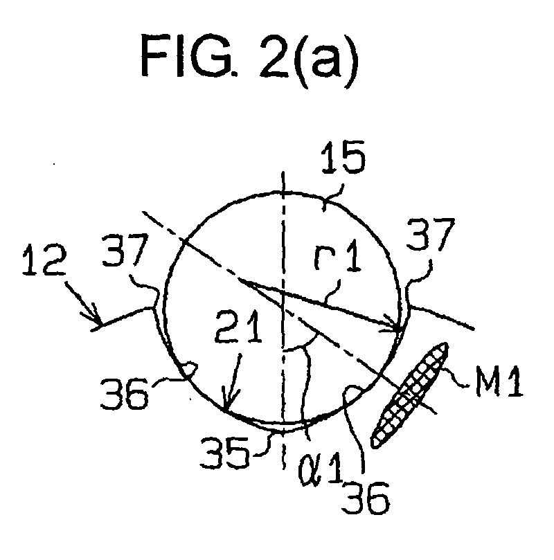
- Figure 2(a) is a cross-section taken along the line A-A of the opening portion side of the first guide track 21 with the ball 15 being located at the lower side of the axis line P2 in Figure 1, namely, of the left side of the inner joint member 12 with respect to the drive shaft 16.
- Figure 2(b) is a cross-section taken along the line B-B of the bottom portion side of the first guide track 21 with the ball 15 being located at the upper side of the axis line P2 in Figure 1, namely, of the right side of the inner joint member 12 with respect to the drive shaft 16.
- Figure 2(a) is illustrated upside down.
- each first guide track 21 of the inner joint member 12 is constituted by two curved surfaces 36 (at right and left as viewed in Figures 2(a) and 2(b)) which intersect with each other at a track bottom center 35.
- Each curved surface 36 is formed so that the curvature radius is gradually enlarged from the opening portion side toward the bottom portion side. That is, of the curvature radius r1 of the curved surface 36 shown in Figure 2(a) and the curvature radius r2 of the curved surface 36 shown in Figure 2(b), the curvature radius r2 is made to be larger.
- the curvature radius r1 is made to be a little larger than the radius of the balls 15.
- the contact angle at which the ball 15 is in contact with the first guide track 21 is made to become smaller gradually from the opening portion side toward the bottom portion side. That is, of the contact angle ⁇ 1 in Figure 2(a) and the contact angle ⁇ 2 in Figure 2(b), the contact angle ⁇ 2 is made to be smaller.
- Each of the “contact angles ⁇ 1 and ⁇ 2" herein means the angle that the contact center of each ball 15 with the first guide track 21 and the track bottom center 35 of the first guide track 21 make with respect to a reference at the center of the ball 15.
- the term "contact center” herein designates a point at which a major axis and a minor axis crosses with each other on an elliptical contact surface (contact ellipse) which is formed by the contact of the first guide track 21 with the ball 15.
- major axis means the axis which constitutes the longest portion in a lengthwise direction of the contact ellipse
- minor axis means the axis which constitutes the longest portion in a shorter-side direction orthogonal to the major axis.
- contact angles ⁇ 1, ⁇ 2 and the curvature radii r1, r2 are set so that contact ellipses M1, M2 each formed by the contact of the ball 15 with the curved surface 36 do not extend beyond (i.e., do not protrude from) edge portions 37 at lateral opposite ends of the first guide track 21.
- an area of the contact ellipse (i.e., contact area) is set to become smaller gradually from the opening portion side toward the bottom portion side.
- the distance between the edge portion 37 and the contact ellipse may be even or uneven over the whole length of the first guide track 21.
- the distance between the edge portion 37 and the contact ellipse can take a suitable distance so far as an excess load is not exerted on the edge portion 37.
- the rotational torque of the same is transmitted from the inner joint member 12 through the balls 15 to the outer joint member 13 thereby to rotate the driven shaft 22 at the same rotational speed as the drive shaft 16.
- the balls 15 are rolled to be guided on the first and second guide tracks 21, 24.
- the balls 15 do not run on the edge portions 37 even when the joint angle is enlarged. This is for the reason why the first guide track 21 is formed so that its contact angle becomes smaller gradually from the opening portion side toward the bottom portion side and why its curvature radius becomes larger gradually from the opening portion side toward the bottom portion side.
- the term "usual use range” means the range within which the ball 15 rolls on the first guide track 21 with the joint angle between the drive shaft 16 and the driven shaft 22 being kept within 0 to around ⁇ 10 degrees. Because the range of the joint angle corresponding to the usual use range varies in dependence on the model of the vehicle using the constant velocity joint 11, the numerical range of the 0 to around ⁇ 10 degrees is the value for illustration purpose, and the present invention is not limited to the numerical range.
- the contact ellipse M2 is defined at the bottom portion side which is less frequency in use than the usual use range and which becomes larger in the joint angle.
- the contact ellipse M2 does not cause the edge portion 37 to suffer from stress even when decrease in the area of the contact ellipse causes the surface pressure to increase. Thus, it does not occur that the edge portion 37 is damaged.
- the inner joint member 12 in the preset embodiment can secure the durability even where it is diminished in thickness, and can be made smaller to the extent that the thickness is diminished.
- a constant velocity joint 51 in the second embodiment is provided by adding a modification onto the first guide track 21 of the constant velocity joint 11 in the first embodiment.
- the same components as those in the first embodiment are omitted from being described in detail by having the same reference numerals put thereon. Therefore, the following description will be made to those which are different from the first embodiment.
- Figure 3(a) is a cross-section taken along the line A-A of the opening portion side of the first guide track 21 with the ball 15 being located at the lower side of the axis line P2 in Figure 1, namely, of the left portion of the inner joint member 12 with respect to the drive shaft 16.
- Figure 3(b) is a cross-section taken along the line B-B of the bottom portion side of the first guide track 21 with the ball 15 being located at the upper side of the axis line P2 in Figure 1, namely, of the right portion of the inner joint member 12 with respect to the drive shaft 16.
- Figure 3(a) is illustrated upside down.
- the inner joint member 12 of the constant velocity joint 51 in the present embodiment is constructed so that the ball 15 is kept in contact with the first guide track 21 at a predetermined contact angle ⁇ 1.
- the first guide track 21 is formed by two right and left (i.e., right and left in Figures 3(a) and 3(b)) curved surfaces 52 which intersect with each other at the track bottom center 35.
- each curved surface 52 is constituted by two curved surface segments 52a, 52b of two different curvature radii r3, r4.
- the curved surface segment 52a with the curvature radius r3 is located at side of the track bottom center 35 (i.e., track bottom side)
- the other curved surface segment 52b with the curvature radius r4 is located at the side of the edge portion 37 (i.e., edge side).
- the curvature radius r3 is chosen to be the same curvature radius as the curvature radius r1 in the first embodiment, and the other curvature radius r4 is chosen to be a larger curvature radius than the curvature radius r3.
- the curved surface segment 52a and the curved surface segment 52b are provided to adjoin each other on a boundary line (b) shown in Figure 3(b).
- the contact angle ⁇ 1 and the curvature radii r3, r4 are set so that the contact ellipses M3 which are formed by the contact of the ball 15 with the curved surfaces 52 each to take an asymmetrical ellipse shape do not extend respectively beyond the edge portions 37 at both lateral sides of the first guide track 21.
- the minor axe S (as shown in Figure 3(c) in an enlarged scale) of each contact ellipse M3 is set to align with the boundary line (b).
- each curved surface (curved surface segment 52b) located closer to the edge portion 37 side than the minor axis (S) is formed to be larger in curvature radius than the curved surface (curved surface segment 52a) located closer to the track bottom center 35 than the minor axis (S).
- the contact ellipse M3 which is asymmetrical at each edge portion 37 side and the track bottom center 35 side is formed by the contact of the ball 15 and each curved surface 52 with a center thereof extending on the minor axis (S). That is, in each of the contact ellipses M3, the area extending from the minor axis (S) toward the edge portion 37 side becomes short in the major axis direction and small in contact area in comparison with the area extending from the minor axis (S) toward the track bottom center 35.
- the constant velocity joint according to the present invention is useful as one which is capable of securing a sufficient contact area of the ball with the guide track without causing the ball to protrude out of the guide track.
- it is suitable for use in constant velocity joints of the ball joint type wherein the angle (i.e., joint angle) between two axes intersecting with each other is variable and wherein the equality of velocity in the transmission of rotational movement is maintained between the both axes.
Landscapes
- Engineering & Computer Science (AREA)
- General Engineering & Computer Science (AREA)
- Mechanical Engineering (AREA)
- Pivots And Pivotal Connections (AREA)
Abstract
Description
- Although in the second embodiment, the inner
joint member 12 is formed to align the minor axis (S) of each contact ellipse M3 with the boundary line (b), the innerjoint member 12 may be formed not to make the minor axis (S) align with the boundary line (b). - In the first embodiment, the contact angle of the
ball 15 with thefirst guide track 21 is made to be diminished gradually from the opening portion side toward the bottom portion side, and the curvature radius for thefirst guide track 21 is made to be enlarged gradually from the opening portion side toward the bottom portion side. Without being limited to this construction, the contact angle on thefirst guide track 21 may be made to take a constant angle from the opening portion side up to a track mid portion and to be diminished gradually from the track mid portion toward the bottom portion side, and the curvature radius may be made to be constant from the opening portion side up to the track mid portion and to be enlarged gradually from track mid portion toward the bottom portion side. - In the second embodiment, only at the bottom portion side of the
first guide track 21, each of thecurved surfaces 52 is formed by the twocurved surface segments curved surfaces 52 may be formed by the twocurved surface segments first guide track 21. - In the second embodiment, the
first guide track 21 is formed so that theball 15 is kept in contact with thefirst guide track 21 at the predetermined contact angle α1. Without being limited to this construction, thefirst guide track 21 may be formed so that the contact angle at which theball 15 is kept in contact with thefirst guide track 21 is diminished gradually from the opening portion side toward the bottom portion side. That is, the innerjoint member 12 may be constructed so that the contact angle α3 in Figure 4 is made smaller than the contact angle α1 in Figure 3(a). - In the first embodiment, the contact angle at which the
ball 15 is kept in contact with thefirst guide track 21 is made to be diminished gradually from the opening portion side toward the bottom portion side, and the curvature radius for thefirst guide track 21 is made to be enlarged gradually from the opening portion side toward the bottom portion side. Without being limited to this construction, the constant velocity joint may be modified so that a machining for the foregoing is implemented only on thesecond guide track 24 or on both of the guide tracks 21, 24. Advantages which are equivalent or superior to those in the first embodiment can be attained even where such modification is made. - In the second embodiment, each of the both
curved surfaces 52 of thefirst guide track 21 is formed by the twocurved surface segments second guide track 24 only or on both of the guide tracks 21, 24. Advantages which are equivalent or superior to those in the second embodiment can be attained even where such modification is made.
Claims (5)
- A constant velocity joint provided with an inner joint member whose outer surface takes a spherical surface and has plural first guide tracks extending in the axial direction thereof; an outer joint member of a cup shape whose internal surface takes a spherical surface and has second guide tracks of the same number as the first guide tracks, extending in the axial direction thereof; a cage fit between the inner and outer joint members; and balls retained respectively in ball retaining windows of the cage and engaged with the first and second guide tracks, characterized in that at least one of each first guide track and each second guide track is made to be smaller in contact angle with the ball at a bottom portion side than at an opening portion side of the outer joint member and is made to be larger in curvature radius for the one guide track at the bottom portion side than at the opening portion side.
- The constant velocity joint as set forth in Clam 1, characterized in that the contact angle is set to become smaller gradually from the opening portion side toward the bottom portion side of the outer joint member, and that the curvature radius is set to become larger gradually from the opening portion side toward the bottom portion side.
- A constant velocity joint provided with an inner joint member whose outer surface takes a spherical surface and has plural first guide tracks extending in the axial direction thereof; an outer joint member of a cup shape whose internal surface takes a spherical surface and has second guide tracks of the same number as the first guide tracks, extending in the axial direction thereof; a cage fit between the inner and outer joint members; and balls retained respectively in ball retaining windows of the cage and engaged with the first and second guide tracks, characterized in that at least at the bottom portion side of the outer joint member, at least one of each first guide track and each second guide track is made smaller in the curvature radius at a track bottom side than in the curvature radius at each edge side of the same guide track.
- The constant velocity joint as set forth in Clam 3, characterized in that over the whole length thereof, at least one of each first guide track and each second guide track is made smaller in the curvature radius at the track bottom side than in the curvature radius at each edge side of the same guide track.
- The constant velocity joint as set forth in Clam 4, characterized in that the contact angle of the ball with the each guide track is made to be smaller at the bottom portion side than at the opening portion side of the outer joint member.
Applications Claiming Priority (3)
| Application Number | Priority Date | Filing Date | Title |
|---|---|---|---|
| JP2002165916 | 2002-06-06 | ||
| JP2002165916A JP2004011760A (en) | 2002-06-06 | 2002-06-06 | Constant velocity joint |
| PCT/JP2003/007105 WO2003104669A1 (en) | 2002-06-06 | 2003-06-05 | Constant velocity joint |
Publications (2)
| Publication Number | Publication Date |
|---|---|
| EP1510711A1 true EP1510711A1 (en) | 2005-03-02 |
| EP1510711A4 EP1510711A4 (en) | 2006-03-15 |
Family
ID=29727614
Family Applications (1)
| Application Number | Title | Priority Date | Filing Date |
|---|---|---|---|
| EP03757196A Withdrawn EP1510711A4 (en) | 2002-06-06 | 2003-06-05 | Constant velocity joint |
Country Status (4)
| Country | Link |
|---|---|
| US (1) | US7128654B2 (en) |
| EP (1) | EP1510711A4 (en) |
| JP (1) | JP2004011760A (en) |
| WO (1) | WO2003104669A1 (en) |
Families Citing this family (9)
| Publication number | Priority date | Publication date | Assignee | Title |
|---|---|---|---|---|
| JP2006300205A (en) * | 2005-04-20 | 2006-11-02 | Toyota Motor Corp | Constant velocity joint and its outer race |
| JP4885236B2 (en) * | 2005-12-29 | 2012-02-29 | ジーケイエヌ ドライヴライン インターナショナル ゲゼルシャフト ミット ベシュレンクテル ハフツング | Fixed constant velocity universal joint with large bending angle |
| US7686696B2 (en) * | 2006-02-24 | 2010-03-30 | Jtekt Corporation | Constant velocity joint |
| EP2554867B1 (en) * | 2010-04-02 | 2022-05-04 | NTN Corporation | Constant velocity universal joint |
| JP5784423B2 (en) * | 2011-09-05 | 2015-09-24 | Ntn株式会社 | Fixed constant velocity universal joint |
| US8852005B2 (en) * | 2011-11-09 | 2014-10-07 | Hyundai Wia Corporation | Angled offset ball type constant velocity joint for vehicle |
| KR101371457B1 (en) * | 2012-06-04 | 2014-03-10 | 현대자동차주식회사 | Constant velocity joint for vehicle |
| JP2016148433A (en) * | 2015-02-13 | 2016-08-18 | 本田技研工業株式会社 | Fixed type constant velocity joint |
| KR20160111127A (en) * | 2015-03-16 | 2016-09-26 | 이래오토모티브시스템 주식회사 | Constant Velocity Joint for vehicle |
Family Cites Families (12)
| Publication number | Priority date | Publication date | Assignee | Title |
|---|---|---|---|---|
| JPS55126124A (en) * | 1979-03-23 | 1980-09-29 | Toyota Motor Corp | Uniform speed ball joint and grinding method of ball groove |
| JPS58214019A (en) * | 1982-06-07 | 1983-12-13 | Toyota Motor Corp | Equal-speed ball joint |
| JPS60167816A (en) | 1984-02-07 | 1985-08-31 | Ricoh Co Ltd | Pc substrate conveyor |
| JPS60167817A (en) | 1984-02-08 | 1985-08-31 | Morinaga & Co Ltd | Surface/back inversion feed device |
| JPS60167816U (en) * | 1984-04-17 | 1985-11-07 | エヌ・テ−・エヌ東洋ベアリング株式会社 | constant velocity universal joint |
| JPS60167817U (en) * | 1984-04-17 | 1985-11-07 | エヌ・テ−・エヌ東洋ベアリング株式会社 | constant velocity universal joint |
| DE3904655C1 (en) * | 1989-02-16 | 1990-02-08 | Uni-Cardan Ag, 5200 Siegburg, De | |
| JP2592333B2 (en) | 1989-08-29 | 1997-03-19 | 株式会社日立製作所 | Air flow sensor element and method of manufacturing the same |
| JPH083712Y2 (en) * | 1989-12-18 | 1996-01-31 | 豊田工機株式会社 | Constant velocity joint |
| JP2678323B2 (en) * | 1990-10-08 | 1997-11-17 | ジー・ケー・エヌ・オートモーティヴ・アクチエンゲゼルシャフト | Constant velocity universal joint |
| DE4443093C1 (en) | 1994-12-03 | 1996-01-04 | Gkn Automotive Ag | Constant=velocity ball=type universal joint |
| DE19941142C2 (en) * | 1999-08-30 | 2002-05-02 | Gkn Automotive Gmbh | Ball constant velocity joint |
-
2002
- 2002-06-06 JP JP2002165916A patent/JP2004011760A/en active Pending
-
2003
- 2003-06-05 WO PCT/JP2003/007105 patent/WO2003104669A1/en not_active Ceased
- 2003-06-05 EP EP03757196A patent/EP1510711A4/en not_active Withdrawn
- 2003-06-05 US US10/513,789 patent/US7128654B2/en not_active Expired - Fee Related
Also Published As
| Publication number | Publication date |
|---|---|
| US7128654B2 (en) | 2006-10-31 |
| JP2004011760A (en) | 2004-01-15 |
| EP1510711A4 (en) | 2006-03-15 |
| WO2003104669A1 (en) | 2003-12-18 |
| US20050202881A1 (en) | 2005-09-15 |
Similar Documents
| Publication | Publication Date | Title |
|---|---|---|
| US4968287A (en) | Constant velocity ratio universal joint | |
| US7407441B2 (en) | Constant velocity joint | |
| US5685777A (en) | Constant velocity universal ball joint | |
| US8216075B2 (en) | Joint arrangement with cage offset | |
| US6506122B2 (en) | Constant velocity universal joint | |
| EP1512879B1 (en) | Fixed type constant velocity universal joint | |
| US7128654B2 (en) | Constant velocity joint | |
| JP5073190B2 (en) | Sliding constant velocity universal joint | |
| EP1705395B1 (en) | Fixed-type constant-velocity universal joint | |
| WO2005068863A1 (en) | Constant velocity joint | |
| JP2002013544A (en) | Constant velocity universal joint | |
| US8251829B2 (en) | Constant velocity ball joint in the form of a counter track joint | |
| JP2003021159A (en) | Constant velocity universal joint | |
| JP2006194268A (en) | Constant velocity joint | |
| WO2024127915A1 (en) | Fixed-type universal joint | |
| CN102985713A (en) | Isokinetic ball joint | |
| US5967900A (en) | Cross-grove type constant velocity joint | |
| JP2009079684A (en) | Fixed type constant velocity universal joint | |
| JP4537304B2 (en) | Fixed constant velocity universal joint | |
| JP2005226781A (en) | Constant velocity universal joint | |
| JPH0140336Y2 (en) | ||
| JPH083712Y2 (en) | Constant velocity joint | |
| JP4268572B2 (en) | Constant velocity joint | |
| JP2001330051A (en) | Constant velocity universal joint | |
| JP3383822B2 (en) | Cross groove type constant velocity universal joint |
Legal Events
| Date | Code | Title | Description |
|---|---|---|---|
| PUAI | Public reference made under article 153(3) epc to a published international application that has entered the european phase |
Free format text: ORIGINAL CODE: 0009012 |
|
| 17P | Request for examination filed |
Effective date: 20041222 |
|
| AK | Designated contracting states |
Kind code of ref document: A1 Designated state(s): AT BE BG CH CY CZ DE DK EE ES FI FR GB GR HU IE IT LI LU MC NL PT RO SE SI SK TR |
|
| RBV | Designated contracting states (corrected) |
Designated state(s): DE FR GB |
|
| A4 | Supplementary search report drawn up and despatched |
Effective date: 20060201 |
|
| RAP1 | Party data changed (applicant data changed or rights of an application transferred) |
Owner name: JTEKT CORPORATION |
|
| RIN1 | Information on inventor provided before grant (corrected) |
Inventor name: SUZUKI, TOMOO,C/O JTEKT CORPORATION Inventor name: OHWAKI, TOMONORI,JTEKT CORPORATION Inventor name: ICHIKAWA, KAZUYUKI,JTEKT CORPORATION |
|
| 17Q | First examination report despatched |
Effective date: 20080222 |
|
| STAA | Information on the status of an ep patent application or granted ep patent |
Free format text: STATUS: THE APPLICATION IS DEEMED TO BE WITHDRAWN |
|
| 18D | Application deemed to be withdrawn |
Effective date: 20080703 |