EP1510628A1 - Steel frame building and joint structure of column and beam - Google Patents
Steel frame building and joint structure of column and beam Download PDFInfo
- Publication number
- EP1510628A1 EP1510628A1 EP03757186A EP03757186A EP1510628A1 EP 1510628 A1 EP1510628 A1 EP 1510628A1 EP 03757186 A EP03757186 A EP 03757186A EP 03757186 A EP03757186 A EP 03757186A EP 1510628 A1 EP1510628 A1 EP 1510628A1
- Authority
- EP
- European Patent Office
- Prior art keywords
- column
- bolt
- reinforcing member
- joint
- plate
- Prior art date
- Legal status (The legal status is an assumption and is not a legal conclusion. Google has not performed a legal analysis and makes no representation as to the accuracy of the status listed.)
- Granted
Links
Images




Classifications
-
- E—FIXED CONSTRUCTIONS
- E04—BUILDING
- E04B—GENERAL BUILDING CONSTRUCTIONS; WALLS, e.g. PARTITIONS; ROOFS; FLOORS; CEILINGS; INSULATION OR OTHER PROTECTION OF BUILDINGS
- E04B1/00—Constructions in general; Structures which are not restricted either to walls, e.g. partitions, or floors or ceilings or roofs
- E04B1/18—Structures comprising elongated load-supporting parts, e.g. columns, girders, skeletons
- E04B1/24—Structures comprising elongated load-supporting parts, e.g. columns, girders, skeletons the supporting parts consisting of metal
-
- E—FIXED CONSTRUCTIONS
- E04—BUILDING
- E04B—GENERAL BUILDING CONSTRUCTIONS; WALLS, e.g. PARTITIONS; ROOFS; FLOORS; CEILINGS; INSULATION OR OTHER PROTECTION OF BUILDINGS
- E04B1/00—Constructions in general; Structures which are not restricted either to walls, e.g. partitions, or floors or ceilings or roofs
- E04B1/18—Structures comprising elongated load-supporting parts, e.g. columns, girders, skeletons
- E04B1/24—Structures comprising elongated load-supporting parts, e.g. columns, girders, skeletons the supporting parts consisting of metal
- E04B1/2403—Connection details of the elongated load-supporting parts
- E04B2001/2418—Details of bolting
-
- E—FIXED CONSTRUCTIONS
- E04—BUILDING
- E04B—GENERAL BUILDING CONSTRUCTIONS; WALLS, e.g. PARTITIONS; ROOFS; FLOORS; CEILINGS; INSULATION OR OTHER PROTECTION OF BUILDINGS
- E04B1/00—Constructions in general; Structures which are not restricted either to walls, e.g. partitions, or floors or ceilings or roofs
- E04B1/18—Structures comprising elongated load-supporting parts, e.g. columns, girders, skeletons
- E04B1/24—Structures comprising elongated load-supporting parts, e.g. columns, girders, skeletons the supporting parts consisting of metal
- E04B1/2403—Connection details of the elongated load-supporting parts
- E04B2001/2445—Load-supporting elements with reinforcement at the connection point other than the connector
-
- E—FIXED CONSTRUCTIONS
- E04—BUILDING
- E04B—GENERAL BUILDING CONSTRUCTIONS; WALLS, e.g. PARTITIONS; ROOFS; FLOORS; CEILINGS; INSULATION OR OTHER PROTECTION OF BUILDINGS
- E04B1/00—Constructions in general; Structures which are not restricted either to walls, e.g. partitions, or floors or ceilings or roofs
- E04B1/18—Structures comprising elongated load-supporting parts, e.g. columns, girders, skeletons
- E04B1/24—Structures comprising elongated load-supporting parts, e.g. columns, girders, skeletons the supporting parts consisting of metal
- E04B1/2403—Connection details of the elongated load-supporting parts
- E04B2001/2448—Connections between open section profiles
-
- E—FIXED CONSTRUCTIONS
- E04—BUILDING
- E04B—GENERAL BUILDING CONSTRUCTIONS; WALLS, e.g. PARTITIONS; ROOFS; FLOORS; CEILINGS; INSULATION OR OTHER PROTECTION OF BUILDINGS
- E04B1/00—Constructions in general; Structures which are not restricted either to walls, e.g. partitions, or floors or ceilings or roofs
- E04B1/18—Structures comprising elongated load-supporting parts, e.g. columns, girders, skeletons
- E04B1/24—Structures comprising elongated load-supporting parts, e.g. columns, girders, skeletons the supporting parts consisting of metal
- E04B1/2403—Connection details of the elongated load-supporting parts
- E04B2001/2457—Beam to beam connections
Definitions
- the present invention relates to a steel-framed building and a joint structure between column and beam.
- Japanese Patents Nos. 2992580 and 2992581 disclose a steel-framed building constructed by joining a column and a beam.
- these conventional techniques do not disclose that section steels having the same cross section are used for the column and the beam, the number of kinds of section steels to be used is undesirably increased, and building costs are increased.
- a reinforcing member provided in a cross section of the beam constituting a beam-side joint and a reinforcing member provided in a cross section of the column constituting a column-side joint can not be formed as the same members.
- the number of kinds of reinforcing members to be used is undesirably increased, and building costs are increased.
- Japanese Patent Application Laid-open No. H11-324129 discloses that a reinforcing member is joined to a cross section of a beam in a beam-side joint by a bolt. An end of a column is joined to a reinforcing member by a bolt, thereby employing a dry joint structure which does not need welding.
- this conventional technique does not disclose that the dry joint structure which need not be welded is employed in a column-side joint. Therefore, in the column-side joint, a horizontal stiffener is welded to the column, and the end of the beam is joined to the horizontal stiffener.
- the column may be bent due to thermal influence of the welding, and a special device such as an assembling jig is required for welding the stiffener.
- a steel-framed building using section steels for a column and a beam wherein section steels having the same cross sections are used for the column and the beam.
- the steel-framed building has a beam-side joint for joining an end of the column to the beam, and a column-side joint for joining an end of the beam to the column.
- the same members are used as both a reinforcing member provided in the cross section of the beam constituting the beam-side joint and a reinforcing member provided in the cross section of the column constituting the column-side joint.
- a joint structure of column-side joint for joining an end of a beam to a column, wherein a reinforcing member is joined to a cross section of the column by a bolt, and an end of the beam is joined to the reinforcing member by a bolt.
- H section steels are used for columns 10 and beams 20, comprising a high floor portion 2 on which the height of each floor is high so that a garage 2A can be provided, and a standard floor portion 3 on which a height of each floor is standard level.
- the beam level of the high floor portion 2 and the beam level of the standard floor portion 3 are different in height, and the high floor portion 2 and the standard floor portion 3 are integrally formed.
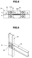
- a joint A between the beam 20 and an upper or lower end of the column 10 is a beam-side joint A which joints an end of the column 10 to the beam 20.
- a joint B between the column 10 and the beam 20 is a beam-side joint, the column 10 is cut by the beam 20 and costs are increased. Therefore, a column-side joint B which joins the end of the beam 20 to a side of the column 10 is used.
- H section steels having the same cross sections are used for the column 10 and the beam 20.
- the cross section of the H section steel has a height of 300mm, a width of 150mm, the thickness of a web is tw and the flange thickness is tf (two or more values of tw and tf may be utilized).
- H section steels having the same cross sections are used for the column 10 and the beam 20. Therefore, the same members can be used as both a reinforcing member 30 provided in the cross section of the beam 20 constituting the beam-side joint A, and a reinforcing member 30 provided in the cross section of the column 10 constituting the column-side joint B.
- the reinforcing members 30 are used such that the reinforcing member 30 is mounted to opposite sides of the web w of the H section steel in the cross section of the beam 20 in the beam-side joint A.
- the reinforcing member 30 is also mounted to opposite sides of the web w of the H section steel in the cross section of the column 10 in the column-side joint B.
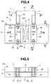
- the reinforcing member 30 comprises two end plates 31 and 32 on opposite ends of the reinforcing member 30, a central groove-type plate 33 as a connecting member for connecting both of the end plates 31 and 32 to each other, and stiffener plates 34 and 35 on opposite sides of the reinforcing member 30.
- the groove-type plate 33 is provided at its web with an X-like strengthening rib 33A. Inner side surfaces of left and right end plates 31 are welded to opposite sides (flanges) on one end side of the groove-type plate 33. Inner side surfaces of left and right end plates 32 are welded to opposite sides (flanges) on the other end side of the groove-type plate 33.
- An outer surface of the left end plate 31 is welded to a side on the one end side of the stiffener plate 34.
- An outer surface of the left end plate 32 is welded to a side of the other end side of the stiffener plate 34.
- An outer surface of the right end plate 31 is welded to a side of the one end side of the stiffener plate 35.
- An outer surface of the right end plate 32 is welded to a side of the other end side of the stiffener plate 35.
- the left and right end plates 31 are provided with one bolt-insertion hole 31A, and the left and right end plates 32 are provided with one bolt-insertion hole 32A.
- an upper flange f1, or a lower flange f2 is provided with two bolt-mounting holes 21, corresponding to bolt-insertion holes 31A of the left and right end plates 31 of the reinforcing member 30.
- a lower flange f2, or an upper flange f1 is provided with two bolt-mounting holes 22, corresponding to bolt-insertion holes 32A of the left and right end plates 32 of the reinforcing member 30.
- planned portions of a plurality of beam-side joints A which are predetermined in the longitudinal direction of the beam 20 may be provided with bolt-mounting holes 21 and 22.
- One selection of the plurality of planned portions may be employed as the beam-side joint A of this embodiment.
- End plate 11 is welded to an end (an upper end or lower end) of the column 10 which constitutes the beam-side joint A.
- each of the opposite sides of the web w of the column 10 is provided with two bolt-insertion holes 11A, corresponding to the bolt-insertion holes 31A of the left and right end plates 31 of the reinforcing member 30.
- an L-shaped plate 12 stands on a periphery of each the bolt-insertion holes 11A.
- the L-shaped plate 12 has an L-shaped cross section, and one end thereof is welded to the end plate 11.
- One side of the L-shaped plate 12 is welded to the web w of the column 10, and the other side of the L-shaped plate 12 is welded to an outer edge of the flange f of the column 10.
- the beam-side joint A is constructed according to the following procedure:
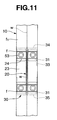
- the fastening force of bolt 51 is set such that the end plate 11 of the column 10 is not opened from the flange f1 of the beam 20 by a moment applied to the beam-side joint A.
- a right flange f1, or a left flange f2 is provided with two bolt-mounting holes 13, corresponding to bolt-insertion holes 31A of the left and right end plates 31 of the reinforcing member 30.
- a left flange f2, or a right flange f1 is provided with two bolt-mounting holes 14, corresponding to bolt-insertion holes 32A of the left and right end plates 32 of the reinforcing member 30.
- planned portions of a plurality of column-side joints B which are predetermined in the longitudinal direction of the column 10 may be provided with the bolt-mounting holes 13 and 14.
- One of the plurality of planned portions may be employed as the column-side joint B of this embodiment.
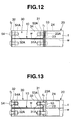
- End plate 23 is welded to an end (left end or right end) of the beam 20 which constitutes the column-side joint B.
- each of the opposite sides of the web w of the beam 20 is provided with two bolt-insertion holes 23A, corresponding to the bolt-insertion holes 31A of the left and right end plates 31 of the reinforcing member 30.
- an L-shaped plate 24 stands on theperiphery of each the bolt-insertion holes 23A.
- the L-shaped plate 24 has an L-shaped cross section, and one end thereof is welded to the end plate 23.
- One side of the L-shaped plate 24 is welded to the web w of the beam 20, and the other side of the L-shaped plate 24 is welded to an outer edge of the flange f of the beam 20.
- the column-side joint B is constructed according to the following procedure:
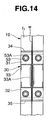
- the fastening force of bolt 53 is set such that the end plate 23 of the beam 20 is not opened from the flange f1 of column 10 by a moment applied to the column-side joint B.
- section steels of the column and the beam are not limited to the H section steel, and other section steel such as C section steels can also be used.
- Other forms may be employed for the reinforcing member.
- a steel-framed building using column and beam construction it is possible to reduce the number of kinds of section steels to be used.
- in a steel-framed building using column and beam construction it is possible to reduce the number of kinds of reinforcing members to be used for a joint between a column and a beam.
- a dry joint structure using no welding can be employed in a column-side joint.
Landscapes
- Engineering & Computer Science (AREA)
- Architecture (AREA)
- Physics & Mathematics (AREA)
- Electromagnetism (AREA)
- Civil Engineering (AREA)
- Structural Engineering (AREA)
- Joining Of Building Structures In Genera (AREA)
Abstract
Description
Claims (7)
- A steel-framed building using section steels for a column and a beam, wherein section steels having the same cross sections are used for the column and the beam,
a beam-side joint for joining an end of the column to the beam, and a column-side joint for joining an end of the beam to the column, and
the same members are used as both a reinforcing member disposed at a cross section of the beam as a beam-side joint, and a reinforcing member disposed at a the cross section of the column as a column-side joint. - A steel-framed building according to claim 1, wherein
in the beam-side joint, the reinforcing member is jointed within the cross section of the beam by a bolt, and an end of the column is joined with the reinforcing member by a bolt,
in the column-side joint, the reinforcing member is joined in the cross section of the column by a bolt, and an end of the beam is jointed to the reinforcing member by a bolt. - A joint structure of a column-side joint for joining an end of a beam to a column, wherein
a reinforcing member is joined in a cross section of the column by a bolt, and an end of the beam is joined with the reinforcing member by a bolt. - A joint structure of a column and a beam according to claim 3,
the reinforcing member having end plates at its opposite ends, and a connecting member for connecting the end plates to each other, the end plate on one end side being joined with one of the flanges of the column by a bolt, and the end plate on the other end side being joined with the other flange of the column by a bolt. - A joint structure of a column and a beam according to claim 4,
the connecting member having a groove-type plate disposed at a central portion and stiffener plates disposed at left and right opposite sides,
inner surfaces of left and right end plates being welded to opposite sides of one end side of the groove-type plate, and inner surfaces of left and right end plates being welded to opposite sides of the other end side of the groove-type plate,
an outer surface of the left end plate being welded to a side of the one end side of the left stiffener plate, and an outer surface of the left end plate being welded to a side of the other end side of the left stiffener plate,
an outer surface of the right end plate being welded to a side of the one end side of the right stiffener plate, an outer surface of the right end plate being welded to a side of the other end side of the right stiffener plate. - A joint structure of a column and a beam according to claim 4, wherein
the groove-type plate has an X-shaped strengthening rib. - A steel-framed building according to claim 1, wherein
a bolt-mounting hole is previously provided in each of the planned portions of a plurality of beam-side joints or column-side joints preset in a longitudinal direction of the beam or column, selected one of the plurality of planned portions is employed as a beam-side joint or column-side joint of this time.
Applications Claiming Priority (3)
| Application Number | Priority Date | Filing Date | Title |
|---|---|---|---|
| JP2002164473A JP4028759B2 (en) | 2002-06-05 | 2002-06-05 | Steel structure and column / beam connection structure |
| JP2002164473 | 2002-06-05 | ||
| PCT/JP2003/003282 WO2003104578A1 (en) | 2002-06-05 | 2003-03-18 | Steel frame building and joint structure of column and beam |
Publications (3)
| Publication Number | Publication Date |
|---|---|
| EP1510628A1 true EP1510628A1 (en) | 2005-03-02 |
| EP1510628A4 EP1510628A4 (en) | 2006-02-08 |
| EP1510628B1 EP1510628B1 (en) | 2007-05-09 |
Family
ID=29727570
Family Applications (1)
| Application Number | Title | Priority Date | Filing Date |
|---|---|---|---|
| EP03757186A Expired - Lifetime EP1510628B1 (en) | 2002-06-05 | 2003-03-18 | Steel frame building and joint structure of column and beam |
Country Status (10)
| Country | Link |
|---|---|
| US (1) | US7637069B2 (en) |
| EP (1) | EP1510628B1 (en) |
| JP (1) | JP4028759B2 (en) |
| KR (1) | KR100961015B1 (en) |
| CN (1) | CN100342094C (en) |
| AU (1) | AU2003220905A1 (en) |
| DE (1) | DE60313771T2 (en) |
| HK (1) | HK1080527B (en) |
| TW (1) | TWI226402B (en) |
| WO (1) | WO2003104578A1 (en) |
Families Citing this family (13)
| Publication number | Priority date | Publication date | Assignee | Title |
|---|---|---|---|---|
| ES2253967B1 (en) * | 2004-01-16 | 2007-03-16 | Ibañez Lazurtegui, S.L. | RIGID UNION SYSTEM SCREWED FOR METAL STRUCTURES. |
| DE102006052854B4 (en) * | 2006-11-09 | 2012-05-10 | Eisenmann Ag | Large cubicle for the treatment of workpieces |
| WO2011004895A1 (en) * | 2009-07-09 | 2011-01-13 | 新日本製鐵株式会社 | Rolled h-section steel beam |
| ES2398757B1 (en) * | 2011-02-18 | 2014-01-21 | Modultec, S.L. | SYSTEM OF UNION OF MODULES BETWEEN PLANTS FOR MODULAR CONSTRUCTION BUILDINGS. |
| JP2013036165A (en) * | 2011-08-03 | 2013-02-21 | Asahi Kasei Homes Co | Building |
| US9394679B2 (en) * | 2011-09-14 | 2016-07-19 | Senqcia Corporation | Connection structure of beam and column, and connection member |
| WO2014047145A1 (en) * | 2012-09-18 | 2014-03-27 | Wayne Amstrong | Modular support systems |
| US10113768B2 (en) | 2015-01-23 | 2018-10-30 | Mitek Holdings, Inc. | Insulated panel assembly |
| US9464427B2 (en) * | 2015-01-23 | 2016-10-11 | Columbia Insurance Company | Light gauge steel beam-to-column joint with yielding panel zone |
| JP6370819B2 (en) * | 2016-02-03 | 2018-08-08 | 東芝三菱電機産業システム株式会社 | Rotating electric machine |
| JP6594932B2 (en) * | 2017-07-20 | 2019-10-23 | 株式会社飯田産業 | Column fixing bracket |
| JP6322329B1 (en) * | 2017-11-22 | 2018-05-09 | 株式会社神戸製鋼所 | Door beam |
| JP7754674B2 (en) * | 2021-09-30 | 2025-10-15 | 大和ハウス工業株式会社 | Beams with end plates and beam-to-column joints |
Family Cites Families (16)
| Publication number | Priority date | Publication date | Assignee | Title |
|---|---|---|---|---|
| JPS5419681B2 (en) | 1971-10-15 | 1979-07-17 | ||
| US3952472A (en) * | 1972-10-05 | 1976-04-27 | Boehmig Robert L | Joint for transferring bending moments |
| JPS5316617A (en) | 1976-07-30 | 1978-02-15 | Kawai Musical Instr Mfg Co | Key signal generator using piezooelectric element for electronic instrument |
| JPS62120602A (en) | 1985-11-20 | 1987-06-01 | Matsushita Electric Ind Co Ltd | Tape guide drum device |
| JPH02229339A (en) | 1989-02-28 | 1990-09-12 | Daiwa House Ind Co Ltd | Rigid joining structure for column and beam |
| JPH0444545A (en) | 1990-06-12 | 1992-02-14 | Nikken Sekkei Ltd | Joint of column and beam and reinforcing metal |
| JPH04339936A (en) | 1991-05-17 | 1992-11-26 | Sekisui House Ltd | Device for beam-column jointing |
| JP2875106B2 (en) * | 1992-06-30 | 1999-03-24 | 敏郎 鈴木 | Reinforcement structure and metal fittings for structural members |
| US6073405A (en) | 1995-12-22 | 2000-06-13 | Icf Kaiser Engineers, Inc. | Fitting for effecting bolted connection between a beam and a column in a steel frame structure |
| JPH1193258A (en) | 1997-09-19 | 1999-04-06 | Nippon Steel Corp | Beam-column joint structure |
| JPH11324129A (en) | 1998-05-18 | 1999-11-26 | Sekisui Chem Co Ltd | Joint structure of columns to beams and building units |
| JP2000226890A (en) | 1999-02-05 | 2000-08-15 | Sekisui House Ltd | Multi-function frame system joint parts |
| JP2000291139A (en) | 1999-04-12 | 2000-10-17 | Kooyoo Create:Kk | Construction method for steel framework |
| US6430890B1 (en) * | 2000-03-28 | 2002-08-13 | Dietrich Industries, Inc. | Web stiffener |
| CN2438761Y (en) * | 2000-06-23 | 2001-07-11 | 李得文 | Butt joint structure of straight column and beam |
| US6609344B2 (en) * | 2001-11-21 | 2003-08-26 | Eluterio Saldana | Connectors, tracks and system for smooth-faced metal framing |
-
2002
- 2002-06-05 JP JP2002164473A patent/JP4028759B2/en not_active Expired - Fee Related
-
2003
- 2003-03-18 KR KR1020047019721A patent/KR100961015B1/en not_active Expired - Fee Related
- 2003-03-18 CN CNB038128039A patent/CN100342094C/en not_active Expired - Fee Related
- 2003-03-18 WO PCT/JP2003/003282 patent/WO2003104578A1/en not_active Ceased
- 2003-03-18 US US10/516,462 patent/US7637069B2/en not_active Expired - Fee Related
- 2003-03-18 HK HK06100225.1A patent/HK1080527B/en not_active IP Right Cessation
- 2003-03-18 EP EP03757186A patent/EP1510628B1/en not_active Expired - Lifetime
- 2003-03-18 DE DE60313771T patent/DE60313771T2/en not_active Expired - Fee Related
- 2003-03-18 AU AU2003220905A patent/AU2003220905A1/en not_active Abandoned
- 2003-03-25 TW TW092106618A patent/TWI226402B/en not_active IP Right Cessation
Also Published As
| Publication number | Publication date |
|---|---|
| TW200307778A (en) | 2003-12-16 |
| JP4028759B2 (en) | 2007-12-26 |
| WO2003104578A1 (en) | 2003-12-18 |
| DE60313771T2 (en) | 2008-01-24 |
| HK1080527B (en) | 2008-01-25 |
| KR20050004282A (en) | 2005-01-12 |
| CN1659343A (en) | 2005-08-24 |
| CN100342094C (en) | 2007-10-10 |
| US7637069B2 (en) | 2009-12-29 |
| JP2004011217A (en) | 2004-01-15 |
| AU2003220905A1 (en) | 2003-12-22 |
| US20050247007A1 (en) | 2005-11-10 |
| EP1510628A4 (en) | 2006-02-08 |
| DE60313771D1 (en) | 2007-06-21 |
| HK1080527A1 (en) | 2006-04-28 |
| EP1510628B1 (en) | 2007-05-09 |
| TWI226402B (en) | 2005-01-11 |
| KR100961015B1 (en) | 2010-06-01 |
Similar Documents
| Publication | Publication Date | Title |
|---|---|---|
| JP4044483B2 (en) | Bonding structure of structures using gusset plates and buildings | |
| EP1510628B1 (en) | Steel frame building and joint structure of column and beam | |
| JP2002327495A (en) | Shaped steel fittings and connection structure | |
| KR20200114876A (en) | Permanent Beam Form | |
| JP7791695B2 (en) | Beam structure with reinforced beams and connecting members | |
| JP5268470B2 (en) | How to lift a rebar basket | |
| JP2657026B2 (en) | Column / beam joint structure | |
| JPH10252142A (en) | Joint structure of steel members | |
| JP5788931B2 (en) | Building frame | |
| JP2000234387A (en) | Joint method and structure of reinforced concrete column and steel beam, and steel beam | |
| JP7563676B2 (en) | Steel structural members and wooden boards connected together | |
| JP2634731B2 (en) | Column-beam connection structure of building unit | |
| JP4327624B2 (en) | Combined beam joining device | |
| JP5010406B2 (en) | Building unit and unit building | |
| JP2006002365A (en) | Building reinforcement structure | |
| JP4157824B2 (en) | Column-beam connection structure | |
| JPH078644Y2 (en) | Joint structure of columns / beams and diagonal members | |
| JP3503601B2 (en) | Orthogonal joint structure of composite beam | |
| JPH10159175A (en) | Joint structure between steel column and beam | |
| JPH0745681Y2 (en) | Lattice beam joint structure | |
| JP2006176979A (en) | Joining structure of structural member for construction | |
| JP2895815B2 (en) | Floor panel mounting structure | |
| JPH06316923A (en) | Steel elements and double steel shell elements | |
| JPH0552383B2 (en) | ||
| JP3319619B2 (en) | Pillar joining equipment |
Legal Events
| Date | Code | Title | Description |
|---|---|---|---|
| PUAI | Public reference made under article 153(3) epc to a published international application that has entered the european phase |
Free format text: ORIGINAL CODE: 0009012 |
|
| 17P | Request for examination filed |
Effective date: 20041119 |
|
| AK | Designated contracting states |
Kind code of ref document: A1 Designated state(s): AT BE BG CH CY CZ DE DK EE ES FI FR GB GR HU IE IT LI LU MC NL PT RO SE SI SK TR |
|
| AX | Request for extension of the european patent |
Extension state: AL LT LV MK |
|
| DAX | Request for extension of the european patent (deleted) | ||
| RBV | Designated contracting states (corrected) |
Designated state(s): DE FR GB |
|
| A4 | Supplementary search report drawn up and despatched |
Effective date: 20051228 |
|
| GRAP | Despatch of communication of intention to grant a patent |
Free format text: ORIGINAL CODE: EPIDOSNIGR1 |
|
| GRAS | Grant fee paid |
Free format text: ORIGINAL CODE: EPIDOSNIGR3 |
|
| GRAA | (expected) grant |
Free format text: ORIGINAL CODE: 0009210 |
|
| AK | Designated contracting states |
Kind code of ref document: B1 Designated state(s): DE FR GB |
|
| REG | Reference to a national code |
Ref country code: GB Ref legal event code: FG4D |
|
| REF | Corresponds to: |
Ref document number: 60313771 Country of ref document: DE Date of ref document: 20070621 Kind code of ref document: P |
|
| ET | Fr: translation filed | ||
| PLBE | No opposition filed within time limit |
Free format text: ORIGINAL CODE: 0009261 |
|
| STAA | Information on the status of an ep patent application or granted ep patent |
Free format text: STATUS: NO OPPOSITION FILED WITHIN TIME LIMIT |
|
| 26N | No opposition filed |
Effective date: 20080212 |
|
| GBPC | Gb: european patent ceased through non-payment of renewal fee |
Effective date: 20080318 |
|
| REG | Reference to a national code |
Ref country code: FR Ref legal event code: ST Effective date: 20081125 |
|
| PG25 | Lapsed in a contracting state [announced via postgrant information from national office to epo] |
Ref country code: DE Free format text: LAPSE BECAUSE OF NON-PAYMENT OF DUE FEES Effective date: 20081001 |
|
| PG25 | Lapsed in a contracting state [announced via postgrant information from national office to epo] |
Ref country code: FR Free format text: LAPSE BECAUSE OF NON-PAYMENT OF DUE FEES Effective date: 20080331 |
|
| PG25 | Lapsed in a contracting state [announced via postgrant information from national office to epo] |
Ref country code: GB Free format text: LAPSE BECAUSE OF NON-PAYMENT OF DUE FEES Effective date: 20080318 |