JP5788931B2 - Building frame - Google Patents
Building frame Download PDFInfo
- Publication number
- JP5788931B2 JP5788931B2 JP2013156399A JP2013156399A JP5788931B2 JP 5788931 B2 JP5788931 B2 JP 5788931B2 JP 2013156399 A JP2013156399 A JP 2013156399A JP 2013156399 A JP2013156399 A JP 2013156399A JP 5788931 B2 JP5788931 B2 JP 5788931B2
- Authority
- JP
- Japan
- Prior art keywords
- heavy steel
- floor
- joining
- joined
- ramen
- Prior art date
- Legal status (The legal status is an assumption and is not a legal conclusion. Google has not performed a legal analysis and makes no representation as to the accuracy of the status listed.)
- Active
Links
Images


Description
本発明は、建物の架構体に関する。 The present invention relates to a building frame.
建物の架構体として、従来、重量鉄骨の柱と梁を剛接合したラーメン構造から成るものや、軽量鉄骨の柱と梁をピン接合した軸組構造から成るものが、知られている。 2. Description of the Related Art Conventionally, building structures are known that have a rigid frame structure in which heavy steel columns and beams are rigidly connected, and those that have a frame structure in which lightweight steel columns and beams are pin-connected.
建物の架構体をラーメン構造で形成した場合には、柱間に大きな開口幅を設けやすいという利点がある(特許文献1参照)。他方、ラーメン構造は、軸組構造に比べて一般的に高コストであるから、架構体を低コストで提供することが困難になるという問題がある。 When the building frame is formed of a ramen structure, there is an advantage that it is easy to provide a large opening width between columns (see Patent Document 1). On the other hand, since the ramen structure is generally more expensive than the frame structure, there is a problem that it is difficult to provide the frame structure at a low cost.
これに対して、建物の架構体を軸組構造で形成した場合には、低コスト化が可能となる。しかし、一階部分に駐車スペースや店舗スペースを設けようとするときには、一階部分の柱間に大きな開口幅を設けることが困難である点が、問題となる。 On the other hand, when the building frame is formed of a frame structure, the cost can be reduced. However, when a parking space or a store space is to be provided on the first floor, it is difficult to provide a large opening width between the pillars on the first floor.
本発明は、前記した従来の問題を解決するものである。 The present invention solves the above-described conventional problems.
即ち、本発明は、一階部分にて柱間に大きな開口幅を設けやすい構造からなる建物の架構体を、低コストで提供することを課題とする。 That is, this invention makes it a subject to provide the structure of a building which consists of a structure which is easy to provide a large opening width between pillars in the first floor part at low cost.
前記課題を解決するために、本発明を、下記構成を具備する建物の架構体とする。 In order to solve the above problems, the present invention is a building frame having the following configuration.
本発明は、軽量鉄骨柱と軽量鉄骨梁とをピン接合させ、各階に耐力壁を構成するように二階以上で形成した軸組構造と、重量鉄骨柱と重量鉄骨梁とを剛接合させて形成したラーメン構造と、前記軸組構造と前記ラーメン構造を接合させる接合金具とを備える。前記軸組構造は、基礎上に組み立てられる一階部分と、この一階部分から迫り出して形成される上階部分とを有する。前記ラーメン構造は、前記基礎上に所定距離を隔てて一対の前記重量鉄骨柱を立設し、且つ、一対の前記重量鉄骨柱の互いの頭部間に前記重量鉄骨梁を架設することで形成した門型ラーメンを有する。前記門型ラーメンを形成する一対の前記重量鉄骨柱の頭部と、前記軸組構造の前記上階部分が有する迫出し領域の床構造とを、前記接合金具を介して接合させる。 The present invention is formed by pin-bonding a lightweight steel column and a lightweight steel beam, and by rigidly joining a heavy-weight steel column and a heavy steel beam to a shaft structure formed on two or more floors so as to form a bearing wall on each floor. And a joint fitting for joining the frame structure and the ramen structure. The shaft structure includes a first floor portion assembled on a foundation and an upper floor portion formed by protruding from the first floor portion. The ramen structure is formed by standing a pair of the heavy steel columns on the foundation at a predetermined distance and constructing the heavy steel beams between the heads of the pair of heavy steel columns. It has a portal ramen. The heads of the pair of heavy steel pillars forming the portal ramen and the floor structure of the protruding area of the upper floor portion of the frame structure are joined via the joint fitting.
本発明において、前記接合金具は、前記重量鉄骨柱の頭部に接合される下プレートと、前記上階部分の床構造に接合される上プレートと、前記下プレートと前記上プレートを結合させる縦リブとを有することが好ましい。 In the present invention, the joining bracket includes a lower plate joined to a head portion of the heavy steel column, an upper plate joined to a floor structure of the upper floor portion, and a longitudinal plate for joining the lower plate and the upper plate. It is preferable to have a rib.
また、本発明において、前記ラーメン構造は、前記門型ラーメンに加えて、一対の前記重量鉄骨柱の前記頭部からそれぞれ屋内方向に延設される屋内側重量鉄骨梁を有し、前記屋内側重量鉄骨梁を、前記上階部分の床構造に接合させることが好ましい。 Further, in the present invention, the ramen structure has an indoor heavy steel beam extending in the indoor direction from the heads of the pair of heavy steel columns in addition to the portal ramen, and the indoor side It is preferable to join a heavy steel beam to the floor structure of the upper floor portion.
このとき、前記接合金具とは別の梁接合金具を更に備え、前記屋内側重量鉄骨梁の先端部と、前記上階部分の床構造とを、前記梁接合金具を介して接合させることが好ましい。 At this time, it is preferable to further include a beam joining bracket different from the joint fitting, and to join the tip portion of the indoor heavy steel beam and the floor structure of the upper floor portion via the beam joining bracket. .
また、本発明において、前記ラーメン構造は、前記門型ラーメンに加えて、一対の前記重量鉄骨柱の頭部からそれぞれ屋外方向に延設される屋外側重量鉄骨梁を有し、前記屋外側重量鉄骨梁を、前記上階部分の床構造に接合させることが好ましい。 Further, in the present invention, the ramen structure includes an outdoor-side heavy steel beam extending in an outdoor direction from the heads of the pair of heavy steel columns in addition to the portal ramen, and the outdoor-side weight It is preferable to join the steel beam to the floor structure of the upper floor portion.
このとき、前記接合金具とは別の梁接合金具を更に備え、前記屋外側重量鉄骨梁の先端部と、前記上階部分の床構造とを、前記梁接合金具を介して接合させることが好ましい。 At this time, it is preferable to further include a beam joining bracket different from the joining bracket, and to join the tip of the outdoor-side heavy steel beam and the floor structure of the upper floor portion via the beam joining bracket. .
本発明は、一階部分にて柱間に大きな開口幅を設けることが容易な構造を備える建物の架構体を、低コストで提供することができるという効果を奏する。 The present invention has an effect of providing a building frame having a structure in which it is easy to provide a large opening width between pillars on the first floor portion at a low cost.
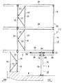
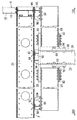
本発明の第1実施形態の建物の架構体を、図1〜図7に基づいて説明する。 The building frame of the first embodiment of the present invention will be described with reference to FIGS.
図1、図2には、本実施形態の建物の架構体を示している。図1は、架構体を側方から視た図であり、図2は、架構体を前方から視た図である。 1 and 2 show a building frame of the present embodiment. FIG. 1 is a side view of the frame body, and FIG. 2 is a view of the frame body from the front.
図中では、前方向を矢印100、後方向を矢印200、左方向を矢印300、右方向を矢印400で示している。
In the drawing, the forward direction is indicated by an
架構体は、コンクリートを打設した基礎4上に組み立てられる一階部分6と、一階部分6の上に組み立てられる二階部分8及び三階部分10を有する。以下の本文中では、二階部分8と三階部分10をまとめて上階部分12と称する。
The frame has a
なお、本実施形態の建物は三階建てであるが、二階建ての建物であれば、その二階部分だけが上階部分12となる。四階以上の建物であれば、二階からその最上階の部分が上階部分12となる。
In addition, although the building of this embodiment is a three-story building, if it is a two-story building, only the 2nd floor part will become the
本実施形態の架構体においては、一階部分6のうち後側の領域と、上階部分12の全部とが、軽量鉄骨を用いた軸組構造14で形成される。一階部分6のうち前側の領域は、重量鉄骨を用いたラーメン構造16で形成される。
In the frame body of the present embodiment, the rear region of the
軸組構造14では、軽量鉄骨の柱である軽量鉄骨柱18と、軽量鉄骨の梁である軽量鉄骨梁20とを、ピン接合により接合させる。また、一階から三階の各階において、隣接する軽量鉄骨柱18間に耐力ブレース22を介在させて、耐力壁24を形成している。
In the
軸組構造14の上階部分12は、軸組構造14の一階部分6から水平方向(ここでは前方向100)に大きく迫り出して形成されている(図1参照)。ここでは、上階部分12の前方に迫り出した領域を、上階部分12が有する迫出し領域2とする。
The
ラーメン構造16は、軸組構造14の上階部分12が有する迫出し領域2を、下方から強固に支持する構造である。ラーメン構造16では、重量鉄骨の柱である重量鉄骨柱26と、重量鉄骨の梁である重量鉄骨梁28とを、多数のボルト等を用いた剛接合により接合させることで、門型ラーメン30を形成する。
The
門型ラーメン30は、水平方向(左右方向)に所定の距離をあけて基礎4上に立設される一対の重量鉄骨柱26と、一対の重量鉄骨柱26の互いの頭部間に架設される重量鉄骨梁28とで、正面視において門型となるように形成される。
The
角型鋼管柱である重量鉄骨柱26の頭部と、H型綱梁である重量鉄骨梁28の左右方向の端部とは、T字鋼から成る継手金具32と、後述の接合金具34とを用いて、剛接合される(図2、図5参照)。
The head of the
継手金具32は、重量鉄骨柱26の側面にボルト及びナットを用いて接合される縦片部36と、縦片部36の中間位置から直交方向に延設される横片部38とを、一体に有する。横片部38は、H型綱梁である重量鉄骨梁28が有する下側フランジの下面に対して、複数のボルト及びナットを用いて接合される。重量鉄骨梁28が有する上側フランジの上面には、接合金具34が、複数のボルト及びナットを用いて接合される。
The joint fitting 32 integrally includes a
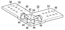
図3に斜視で示すように、接合金具34は、平面視L字型である下プレート40と、下プレート40の中間部分46の上方に位置する平面視矩形状の上プレート42と、上下方向に対向位置する両プレート40,42同士を結合させる複数の縦リブ44とを、一体に有する。
As shown in a perspective view in FIG. 3, the joining
下プレート40と上プレート42とは、平面視での寸法形状が互いに相違し、上下方向の厚みも互いに相違する。下プレート40は、上プレート42よりも大きな平面積を有し、且つ、上プレート42よりも大きな厚みを有する。
The
平面視L字型である下プレート40は、L字型の角をなす中間部分46と、この中間部分46から一方向に延びる第一延設部分48と、第一延設部分48とは直交方向に延びる第二延設部分50とから成る。
The
下プレート40の中間部分46は、溶接によって重量鉄骨柱26の頭部に接合される。
The
第一延設部分48には複数のボルト孔52を穿設している。このボルト孔52に挿入するボルト及びナットによって、第一延設部分48は、重量鉄骨梁28が有する上側フランジの上面に接合される(図5参照)。
A plurality of bolt holes 52 are formed in the first extending
本実施形態のラーメン構造16は、前記のように形成される門型ラーメン30に加えて、一対の重量鉄骨柱26の頭部からそれぞれ屋内方向(ここでは後方向200)に延設される屋内側重量鉄骨梁54を有する(図1、図6、図7参照)。
In addition to the
H型鋼梁である屋内側重量鉄骨梁54の屋外方向(ここでは前方向100)の端部は、角型鋼管柱である重量鉄骨柱26の頭部に対して、前記した継手金具32と同様の構造を有する継手金具78と、接合金具34の第二延設部分50とを用いて、剛接合される(図6参照)。
The end portion in the outdoor direction (here, the front direction 100) of the indoor
つまり、T字状である継手金具78の縦片部80が、重量鉄骨柱26の側面にボルト及びナットを用いて接合される。継手金具78の横片部82は、H型鋼梁である屋内側重量鉄骨梁54が有する下側フランジの下面に、複数のボルト及びナットを用いて接合される。
That is, the
屋内側重量鉄骨梁54が有する上側フランジの上面には、接合金具34の第二延設部分50が接合される。第二延設部分50には複数のボルト孔56を穿設しており、このボルト孔56に挿入するボルト及びナットによって、屋内側重量鉄骨梁54と第二延設部分50が接合される。
The second extending
前記のように構成されるラーメン構造16は、重量鉄骨柱26の頭部に溶接した接合金具34と、これとは別の梁接合金具58,70を用いて、軸組構造14の二階部分8の床構造に接合される。
The
図3に示すように、接合金具34が有する平面視矩形状の上プレート42には、複数のボルト孔59を穿設している。このボルト孔59に挿入するボルト及びナットによって、上プレート42は、二階部分8の床構造をなす軽量鉄骨梁20に接合される。
As shown in FIG. 3, a plurality of bolt holes 59 are formed in the
門型ラーメン30から片持ち梁のように延設される屋内側重量鉄骨梁54の先端部は、梁接合金具58を介して、軸組構造14の二階部分8の軽量鉄骨梁20に接合される(図6参照)。
The distal end portion of the indoor
図4に斜視で示すように、梁接合金具58は、平面視矩形状である下プレート60と、下プレート60の上方に位置する平面視矩形状の上プレート62と、上下方向に対向位置する両プレート60,62同士を結合させる複数の縦リブ64とを、一体に有する。
As shown in a perspective view in FIG. 4, the
平面視において、下プレート60の中心点と上プレート62の中心点とは、互いにずれて位置する。下プレート60は、上プレート62よりも大きな平面積を有し、且つ、上プレート62よりも大きな厚みを有する。
In plan view, the center point of the
下プレート60には複数のボルト孔66を穿設しており、このボルト孔66に挿入するボルト及びナットによって、下プレート60は、屋内側重量鉄骨梁54が有する上側フランジの上面に接合される。
A plurality of bolt holes 66 are formed in the
上プレート62には複数のボルト孔68を穿設しており、このボルト孔68に挿入するボルト及びナットによって、上プレート62は、二階部分8の床構造をなす軽量鉄骨梁20に接合される。
A plurality of bolt holes 68 are formed in the
更に、門型ラーメン30をなす重量鉄骨梁28の左右方向の中央部分には、梁接合金具70を接合させている(図5参照)。重量鉄骨梁28の中央部分は、梁接合金具70を介して、軸組構造14の二階部分8の軽量鉄骨梁20に接合される。
Further, a beam joining metal fitting 70 is joined to the central portion in the left-right direction of the
梁接合金具70は、前記した梁接合金具58と同様の構造を有する。つまり、梁接合金具70は、平面視矩形状である下プレート72と、これの上方に対向位置する平面視矩形状の上プレート74と、両プレート72,74同士を結合させる複数の縦リブ76とを、一体に有する。下プレート72は、重量鉄骨梁28が有する上側フランジの上面に対して複数のボルト及びナットで接合される。上プレート74は、二階部分8の床構造をなす軽量鉄骨梁20に対して複数のボルト及びナットで接合される。
The beam
また、本実施形態では、図1に示すように、基礎4のうち軸組構造14の一階部分6を組み立てる部分よりも、ラーメン構造16を組み立てる部分を、一段下げて形成している。つまり、重量鉄骨柱26を立設する部分が一段下がるように基礎4を形成しているが、このような段差を設けなくてもよい。
Moreover, in this embodiment, as shown in FIG. 1, the part which assembles the
以上のように、本実施形態の建物の架構体は、軽量鉄骨柱18と軽量鉄骨梁20をピン接合させ、各階に耐力壁24を構成するように二階以上で形成した軸組構造14と、重量鉄骨柱26と重量鉄骨梁28を剛接合させて形成したラーメン構造16と、軸組構造14とラーメン構造16を接合させる接合金具34とを備える。
As described above, the frame structure of the building of the present embodiment includes the
軸組構造14は、基礎4上に組み立てられる一階部分6と、この一階部分6から迫り出して形成される上階部分12とを有する。
The
ラーメン構造16は、基礎4上に所定距離を隔てて一対の重量鉄骨柱26を立設し、且つ、一対の重量鉄骨柱26の互いの頭部間に重量鉄骨梁28を架設することで形成した門型ラーメン30を有する。
The
そして、門型ラーメン30を形成する一対の重量鉄骨柱26の頭部と、軸組構造14の上階部分12が有する迫出し領域2の床構造とを、接合金具34を介して接合させている。
Then, the heads of the pair of
これにより、本実施形態の建物の架構体では、建物の一階部分6のうち必要な領域だけを、大きな開口幅(例えば6m程度)を設けるのに有利な門型ラーメン30を有するラーメン構造16で形成し、一階部分6の他の領域と上階部分12を、低コストで提供可能な軸組構造14によって形成することができる。つまり、建物の架構体のうち一階部分6の一部領域はラーメン構造16を用いて高い自由度で設計し、架構体の他の部分については、規格化された軸組構造14を用いて低コストで形成することが可能である。
Thereby, in the building frame of the present embodiment, the
また、本実施形態の建物の架構体は、軸組構造14の上階部分12の床構造(即ち二階部分8の床構造)に対して、接合金具34を介して、重量鉄骨柱26を接合させる構成であるから、二階部分8の床構造における床材の配置や設計、積算、施工などを、軸組構造14の他の部分と共通に設けることができ、低コスト化が図られる。これに対して、例えばラーメン構造16の重量鉄骨梁28を、二階部分8の床梁として利用した場合には、床材に専用の切り欠きが必要になる等、他の軸組構造14の部分とは異なる設計、積算、施工が必要になる。
In the building frame of this embodiment, the
更に、本実施形態の建物の架構体において、接合金具34は、重量鉄骨柱26の頭部に接合される下プレート40と、上階部分12の床構造に接合される上プレート42と、下プレート40と上プレート42を結合させる縦リブ44とを有する。
Further, in the building frame of the present embodiment, the joining
このように、ラーメン構造16との接合に適した寸法形状を有する下プレート40と、軸組構造14との接合に適した寸法形状を有する上プレート42とを、別々に有する接合金具34を用いることで、梁幅等が異なる軸組構造14の床構造と門型ラーメン30とを、簡易に且つ強固に接合させることが可能となる。
As described above, the joining
更に、本実施形態の建物の架構体において、ラーメン構造16は、門型ラーメン30に加えて、一対の重量鉄骨柱26の頭部からそれぞれ屋内方向に延設される屋内側重量鉄骨梁54を有する。屋外側重量鉄骨梁54は、上階部分12の床構造に接合させている。
Further, in the building frame of the present embodiment, the
これにより、屋内側重量鉄骨梁54と、上階部分12の床構造をなす床梁とが一体化されて、高い強度が得られる。特に、重量鉄骨から成る屋内側重量鉄骨梁54を設けたことで、屋内外方向に働く水平力に対して、高い耐力を発揮する。また、屋内側重量鉄骨梁54が高い耐力を発揮するため、軸組構造14の上階部分12の床梁は、軽微な断面仕様で提供することが可能となる。
As a result, the indoor
更に、本実施形態の建物の架構体では、接合金具34とは別の梁接合金具58を更に備え、屋内側重量鉄骨梁54の先端部と、上階部分12の床構造とを、梁接合金具58を介して接合させている。
Furthermore, the building frame of the present embodiment further includes a
このように、専用の梁接合金具58を用いることで、軸組構造14の床構造と屋内側重量鉄骨梁54とを、互いに梁幅等が異なるにも関わらず、簡易に且つ強固に接合させることが可能となる。
In this way, by using the dedicated
次に、本発明の第2実施形態の建物の架構体について、図9〜図11に基づいて説明する。なお、上述した第1実施形態と同様の構成については、同一符号を付して詳細な説明を省略する。以下においては、第1実施形態とは相違する構成について詳述する。 Next, the building frame of the second embodiment of the present invention will be described with reference to FIGS. In addition, about the structure similar to 1st Embodiment mentioned above, the same code | symbol is attached | subjected and detailed description is abbreviate | omitted. In the following, the configuration different from the first embodiment will be described in detail.
本実施形態の建物の架構体において、一階部分6のラーメン構造16は、更に屋外側重量鉄骨梁88を有する。屋外側重量鉄骨梁88は、門型ラーメン30が有する一対の重量鉄骨柱26の頭部から、それぞれ屋外方向(前方向100)に延設される。
In the building frame of the present embodiment, the
H型鋼梁である屋外側重量鉄骨梁88の屋内方向(後方向200)の端部は、角型鋼管柱である重量鉄骨柱26の頭部に対して、継手金具84と接合金具34とを用いて、剛接合される(図10参照)。
The end portion in the indoor direction (rearward direction 200) of the outdoor-side
継手金具84は、屋内側重量鉄骨梁54の接合に用いる継手金具78と、同様の構造を有する。つまり、T字状である継手金具84の縦片部86が、重量鉄骨柱26の側面にボルト及びナットで接合され、継手金具84の横片部87が、屋外側重量鉄骨梁88が有する下側フランジの下面にボルト及びナットで接合される。
The
本実施形態では、接合金具34が、第二延設部分50とは反対側に延設される第三延設部分90を更に有する。第三延設部分90は、第二延設部分50と同様の構造を有し、複数のボルト及びナットによって、屋外側重量鉄骨梁88が有する上側フランジの上面に接合される。第一乃至第三延設部分48,50,90を有する接合金具34は、全体が平面視T字状に形成される。
In the present embodiment, the
門型ラーメン30から片持ち梁のように延設される屋外側重量鉄骨梁88の先端部は、梁接合金具92を介して、軸組構造14の二階部分8の床構造に接合される。
The distal end portion of the outdoor-side
梁接合金具92は、屋内側重量鉄骨梁54を接合させる梁接合金具58と同様の構造を有する。つまり、梁接合金具92は、平面視矩形状である下プレート94と、下プレート94の上方に位置する平面視矩形状の上プレート96と、上下方向に対向位置する両プレート94,96同士を結合させる複数の縦リブ98とを、一体に有する。
The beam
下プレート94は、複数のボルト及びナットによって、屋外側重量鉄骨梁88が有する上側フランジの上面に接合される。上プレート96は、複数のボルト及びナットによって、二階部分8の床構造をなす軽量鉄骨梁20に接合される。
The
本実施形態では、重量鉄骨柱26の頭部から、屋内側重量鉄骨梁54と屋外側重量鉄骨梁88とが互いに離れる方向に延設された、側面視T字状のラーメン構造16を備えているので、屋内外方向に働く水平力に対して、更に高い耐力を発揮する。
In the present embodiment, there is provided a T-shaped
また、屋外側重量鉄骨梁88が、軸組構造14の上階部分12の床梁を更に補強するように機能するので、上階部分12を、一階部分6の重量鉄骨柱26の位置から更に前方向100に大きくオーバーハングさせて設けることも可能となっている。
Moreover, since the outdoor side
以上のように、本実施形態の建物の架構体において、ラーメン構造16は、門型ラーメン30に加えて、一対の重量鉄骨柱26の頭部からそれぞれ屋外方向に延設される屋外側重量鉄骨梁88を有する。この屋外側重量鉄骨梁88を、上階部分12の床構造に接合させている。
As described above, in the building frame of the present embodiment, the
これにより、門型ラーメン30から屋外側に延設される屋外側重量鉄骨梁88が、軸組構造14である上階部分12の床構造を、更に補強する。そのため、この上階部分12を、門型ラーメン30の位置から更に屋外方向に大きくオーバーハングさせて設けることが可能になる等、設計対応範囲の大きな構造となる。
Thereby, the outdoor-side
更に、本実施形態の建物の架構体では、接合金具34とは別の梁接合金具92を更に備え、屋外側重量鉄骨梁88の先端部と、上階部分12の床構造とを、梁接合金具92を介して接合させている。
Furthermore, the building frame of the present embodiment further includes a beam joint 92 that is different from the joint 34, and connects the tip of the outdoor
このように、専用の梁接合金具92を用いることで、軸組構造14の床構造と屋外側重量鉄骨梁88とを、互いに梁幅等が異なるにも関わらず、簡易に且つ強固に接合させることが可能となる。
As described above, by using the dedicated
以上、本発明を、添付図面に示す第1及び第2実施形態に基づいて説明したが、本発明はこれらの実施形態に限定されるものではない。 As mentioned above, although this invention was demonstrated based on 1st and 2nd embodiment shown to an accompanying drawing, this invention is not limited to these embodiment.
例えば、第1及び第2実施形態の建物の架構体において、一階部分6の前面にはラーメン構造16のみが位置するが、図8に示す第1実施形態の変形例のように、一階部分6の前面が、ラーメン構造16とこれに隣接する軸組構造14とで形成されてもよい。
For example, in the building frame of the first and second embodiments, only the
また、第1実施形態のラーメン構造16は、門型ラーメン30と屋内側重量鉄骨梁54から成り、第2実施形態のラーメン構造16は、門型ラーメン30と屋内側及び屋外側重量鉄骨梁54,88から成るが、門型ラーメン30と屋外側重量鉄骨梁88でラーメン構造16を形成してもよいし、門型ラーメン30だけでラーメン構造16を形成してもよい。
The
また、第1及び第2実施形態の建物の架構体では、門型ラーメン30をなす重量鉄骨梁28の中央部分に梁接合金具70を接合させているが、梁接合金具70を接合させる部分は重量鉄骨梁28の中央部分以外であってもよいし、複数個所に梁接合金具70を接合させてもよい。梁接合金具70を介在させない構造も可能である。
Further, in the building frame of the first and second embodiments, the beam joining metal fitting 70 is joined to the central portion of the
また、第1実施形態や第2実施形態の建物の架構体では、接合金具34、梁接合金具58,70,92等の金具を、二階部分8の床構造をなす軽量鉄骨梁20に接合させているが、これらの金具を、二階部分8の床構造をなすジョイントブロック等の他部材に接合させてもよい。
Further, in the building frame of the first embodiment or the second embodiment, the metal fittings such as the
その他の構成についても、本発明の意図する範囲内であれば、各例において適宜の設計変更を行うことや、各例の構成を適宜組み合わせて適用することが可能である。 With respect to other configurations, as long as they are within the range intended by the present invention, it is possible to make appropriate design changes in each example, and to apply the configurations of each example in combination as appropriate.
2 迫出し領域
4 基礎
6 一階部分
12 上階部分
14 軸組構造
16 ラーメン構造
18 軽量鉄骨柱
20 軽量鉄骨梁
26 重量鉄骨柱
28 重量鉄骨梁
30 門型ラーメン
34 接合金具
40 下プレート
42 上プレート
44 縦リブ
54 屋内側重量鉄骨梁
58 梁接合金具
70 梁接合金具
88 屋外側重量鉄骨梁
92 梁接合金具
2
Claims (5)
重量鉄骨柱と重量鉄骨梁とを剛接合させて形成したラーメン構造と、
前記軸組構造と前記ラーメン構造を接合させる接合金具とを備え、
前記軸組構造は、基礎上に組み立てられる一階部分と、この一階部分から迫り出して形成される上階部分とを有し、
前記ラーメン構造は、前記基礎上に所定距離を隔てて一対の前記重量鉄骨柱を立設し、且つ、一対の前記重量鉄骨柱の互いの頭部間に前記重量鉄骨梁を架設することで形成した門型ラーメンと、一対の前記重量鉄骨柱の頭部からそれぞれ屋内方向に延設される屋内側重量鉄骨梁とを有し、
前記門型ラーメンを形成する一対の前記重量鉄骨柱の頭部と、前記軸組構造の前記上階部分が有する迫出し領域の床構造とを、前記接合金具を介して接合させ、前記屋内側重量鉄骨梁を、前記上階部分の床構造に接合させたことを特徴とする建物の架構体。 A shaft structure formed on two or more floors so that a lightweight steel column and a lightweight steel beam are pin-bonded and a bearing wall is formed on each floor,
A rigid frame structure formed by rigidly joining heavy steel columns and heavy steel beams;
A joining bracket for joining the frame structure and the ramen structure;
The shaft structure has a first floor part assembled on a foundation, and an upper floor part formed protruding from the first floor part,
The ramen structure is formed by standing a pair of the heavy steel columns on the foundation at a predetermined distance and constructing the heavy steel beams between the heads of the pair of heavy steel columns. A portal ramen and an indoor heavy steel beam extending in the indoor direction from the heads of the pair of heavy steel columns ,
A pair of the heavy steel column heads forming the portal ramen and a floor structure of a protruding area of the upper floor portion of the frame structure are joined via the joint fitting, and the indoor side A building frame comprising a heavy steel beam joined to the floor structure of the upper floor portion .
重量鉄骨柱と重量鉄骨梁とを剛接合させて形成したラーメン構造と、 A rigid frame structure formed by rigidly joining heavy steel columns and heavy steel beams;
前記軸組構造と前記ラーメン構造を接合させる接合金具とを備え、 A joining bracket for joining the frame structure and the ramen structure;
前記軸組構造は、基礎上に組み立てられる一階部分と、この一階部分から迫り出して形成される上階部分とを有し、 The shaft structure has a first floor part assembled on a foundation, and an upper floor part formed protruding from the first floor part,
前記ラーメン構造は、前記基礎上に所定距離を隔てて一対の前記重量鉄骨柱を立設し、且つ、一対の前記重量鉄骨柱の互いの頭部間に前記重量鉄骨梁を架設することで形成した門型ラーメンと、一対の前記重量鉄骨柱の頭部からそれぞれ屋外方向に延設される屋外側重量鉄骨梁とを有し、 The ramen structure is formed by standing a pair of the heavy steel columns on the foundation at a predetermined distance and constructing the heavy steel beams between the heads of the pair of heavy steel columns. A portal ramen, and an outdoor-side heavy steel beam extending in the outdoor direction from the heads of the pair of heavy steel columns,
前記門型ラーメンを形成する一対の前記重量鉄骨柱の頭部と、前記軸組構造の前記上階部分が有する迫出し領域の床構造とを、前記接合金具を介して接合させ、前記屋外側重量鉄骨梁を、前記上階部分の床構造に接合させたことを特徴とする建物の架構体。 A pair of the heavy steel column heads forming the portal ramen and a floor structure of a protruding region of the upper floor portion of the frame structure are joined via the joint fitting, and the outdoor side A building frame comprising a heavy steel beam joined to the floor structure of the upper floor portion.
前記屋内側重量鉄骨梁の先端部と、前記上階部分の床構造とを、前記梁接合金具を介して接合させたことを特徴とする請求項1に記載の建物の架構体。 It further comprises a beam joining bracket different from the joining bracket,
And the tip portion of the house inner weight steel beam, the upper floor portion of the floor structure, the building of the rack structure according to claim 1, characterized in that is bonded via the beam connecting bracket.
前記屋外側重量鉄骨梁の先端部と、前記上階部分の床構造とを、前記梁接合金具を介して接合させたことを特徴とする請求項2に記載の建物の架構体。 The building frame according to claim 2, wherein a front end portion of the outdoor-side heavy steel beam and a floor structure of the upper floor portion are joined through the beam joint fitting.
Priority Applications (1)
| Application Number | Priority Date | Filing Date | Title |
|---|---|---|---|
| JP2013156399A JP5788931B2 (en) | 2013-07-29 | 2013-07-29 | Building frame |
Applications Claiming Priority (1)
| Application Number | Priority Date | Filing Date | Title |
|---|---|---|---|
| JP2013156399A JP5788931B2 (en) | 2013-07-29 | 2013-07-29 | Building frame |
Publications (2)
| Publication Number | Publication Date |
|---|---|
| JP2015025316A JP2015025316A (en) | 2015-02-05 |
| JP5788931B2 true JP5788931B2 (en) | 2015-10-07 |
Family
ID=52490179
Family Applications (1)
| Application Number | Title | Priority Date | Filing Date |
|---|---|---|---|
| JP2013156399A Active JP5788931B2 (en) | 2013-07-29 | 2013-07-29 | Building frame |
Country Status (1)
| Country | Link |
|---|---|
| JP (1) | JP5788931B2 (en) |
Family Cites Families (1)
| Publication number | Priority date | Publication date | Assignee | Title |
|---|---|---|---|---|
| JP3399582B2 (en) * | 1993-04-26 | 2003-04-21 | 積水ハウス株式会社 | Ramen frame structure |
-
2013
- 2013-07-29 JP JP2013156399A patent/JP5788931B2/en active Active
Also Published As
| Publication number | Publication date |
|---|---|
| JP2015025316A (en) | 2015-02-05 |
Similar Documents
| Publication | Publication Date | Title |
|---|---|---|
| JP4931490B2 (en) | Structure reinforcement structure and method of reinforcement | |
| JP4710067B2 (en) | Beam-column joint structure | |
| JP6408786B2 (en) | Floor beam and floor beam support structure | |
| JP2016211164A (en) | Joint structure | |
| JP6013028B2 (en) | Outer shell structure | |
| JP4853422B2 (en) | Gate frame with connection of composite beams and wooden columns | |
| JP5788931B2 (en) | Building frame | |
| JP5873369B2 (en) | Building overhang structure | |
| JP5123602B2 (en) | Unit type building and construction method of unit type building | |
| KR101409796B1 (en) | Unit modular house connection structure using bent column for unit modular house | |
| KR200477104Y1 (en) | Joint Structure of Steel Tube Column and Steel Beam | |
| JP5967438B2 (en) | Brace seismic reinforcement structure | |
| JP5967642B2 (en) | Building reinforcement structure | |
| JP7087262B2 (en) | Structure | |
| JP6565543B2 (en) | Column and beam joint structure, building with column and beam joint structure | |
| JP5641456B2 (en) | Building material connection structure | |
| JP5142575B2 (en) | Seismic reinforcement method for wooden buildings and wooden buildings | |
| JP4920767B2 (en) | Connection structure of building components | |
| JP5271738B2 (en) | Building unit and unit building | |
| JP5974314B1 (en) | Seismic reinforcement structure for H-shaped steel columns | |
| JP5301700B1 (en) | Attached units and unit buildings | |
| JP7263677B2 (en) | Structure | |
| JP2008297832A (en) | Reinforcement structure of base-isolated building | |
| KR101371198B1 (en) | Square pipe type assembling structural member | |
| JP5647713B2 (en) | Building structure |
Legal Events
| Date | Code | Title | Description |
|---|---|---|---|
| A131 | Notification of reasons for refusal |
Free format text: JAPANESE INTERMEDIATE CODE: A131 Effective date: 20141209 |
|
| A521 | Written amendment |
Free format text: JAPANESE INTERMEDIATE CODE: A523 Effective date: 20150126 |
|
| TRDD | Decision of grant or rejection written | ||
| A01 | Written decision to grant a patent or to grant a registration (utility model) |
Free format text: JAPANESE INTERMEDIATE CODE: A01 Effective date: 20150630 |
|
| A61 | First payment of annual fees (during grant procedure) |
Free format text: JAPANESE INTERMEDIATE CODE: A61 Effective date: 20150730 |
|
| R150 | Certificate of patent or registration of utility model |
Ref document number: 5788931 Country of ref document: JP Free format text: JAPANESE INTERMEDIATE CODE: R150 |
|
| R250 | Receipt of annual fees |
Free format text: JAPANESE INTERMEDIATE CODE: R250 |
|
| R250 | Receipt of annual fees |
Free format text: JAPANESE INTERMEDIATE CODE: R250 |
|
| S533 | Written request for registration of change of name |
Free format text: JAPANESE INTERMEDIATE CODE: R313533 |
|
| R350 | Written notification of registration of transfer |
Free format text: JAPANESE INTERMEDIATE CODE: R350 |