EP1510559A1 - Ink composition and ink jet recording method - Google Patents
Ink composition and ink jet recording method Download PDFInfo
- Publication number
- EP1510559A1 EP1510559A1 EP20040020199 EP04020199A EP1510559A1 EP 1510559 A1 EP1510559 A1 EP 1510559A1 EP 20040020199 EP20040020199 EP 20040020199 EP 04020199 A EP04020199 A EP 04020199A EP 1510559 A1 EP1510559 A1 EP 1510559A1
- Authority
- EP
- European Patent Office
- Prior art keywords
- polymer
- ink
- ink composition
- pigment
- weight
- Prior art date
- Legal status (The legal status is an assumption and is not a legal conclusion. Google has not performed a legal analysis and makes no representation as to the accuracy of the status listed.)
- Granted
Links
- 239000000203 mixture Substances 0.000 title claims abstract description 107
- 238000000034 method Methods 0.000 title claims abstract description 37
- 229920000642 polymer Polymers 0.000 claims abstract description 112
- 239000002245 particle Substances 0.000 claims abstract description 73
- 238000002844 melting Methods 0.000 claims abstract description 41
- 230000008018 melting Effects 0.000 claims abstract description 41
- 239000003086 colorant Substances 0.000 claims abstract description 35
- 239000002612 dispersion medium Substances 0.000 claims abstract description 22
- 230000005686 electrostatic field Effects 0.000 claims abstract description 10
- 239000000463 material Substances 0.000 claims description 53
- 239000011248 coating agent Substances 0.000 claims description 43
- 238000000576 coating method Methods 0.000 claims description 43
- -1 polyethylene Polymers 0.000 claims description 23
- 229920000728 polyester Polymers 0.000 claims description 18
- 150000001875 compounds Chemical class 0.000 claims description 8
- 239000004698 Polyethylene Substances 0.000 claims description 6
- 229920000573 polyethylene Polymers 0.000 claims description 6
- 239000002202 Polyethylene glycol Substances 0.000 claims description 4
- 229920001223 polyethylene glycol Polymers 0.000 claims description 4
- 239000000976 ink Substances 0.000 description 188
- 239000000049 pigment Substances 0.000 description 82
- 239000002609 medium Substances 0.000 description 55
- 239000000126 substance Substances 0.000 description 34
- NIXOWILDQLNWCW-UHFFFAOYSA-M Acrylate Chemical compound [O-]C(=O)C=C NIXOWILDQLNWCW-UHFFFAOYSA-M 0.000 description 27
- OKKJLVBELUTLKV-UHFFFAOYSA-N Methanol Chemical compound OC OKKJLVBELUTLKV-UHFFFAOYSA-N 0.000 description 24
- 230000015572 biosynthetic process Effects 0.000 description 18
- PPBRXRYQALVLMV-UHFFFAOYSA-N Styrene Chemical compound C=CC1=CC=CC=C1 PPBRXRYQALVLMV-UHFFFAOYSA-N 0.000 description 16
- KJIFKLIQANRMOU-UHFFFAOYSA-N oxidanium;4-methylbenzenesulfonate Chemical compound O.CC1=CC=C(S(O)(=O)=O)C=C1 KJIFKLIQANRMOU-UHFFFAOYSA-N 0.000 description 16
- 239000011541 reaction mixture Substances 0.000 description 16
- 239000003795 chemical substances by application Substances 0.000 description 14
- 239000002270 dispersing agent Substances 0.000 description 14
- 238000010438 heat treatment Methods 0.000 description 14
- 239000002904 solvent Substances 0.000 description 14
- 238000011156 evaluation Methods 0.000 description 13
- 150000002430 hydrocarbons Chemical class 0.000 description 12
- CXMXRPHRNRROMY-UHFFFAOYSA-N sebacic acid Chemical compound OC(=O)CCCCCCCCC(O)=O CXMXRPHRNRROMY-UHFFFAOYSA-N 0.000 description 12
- 229920001577 copolymer Polymers 0.000 description 11
- HRPVXLWXLXDGHG-UHFFFAOYSA-N Acrylamide Chemical compound NC(=O)C=C HRPVXLWXLXDGHG-UHFFFAOYSA-N 0.000 description 10
- 125000004432 carbon atom Chemical group C* 0.000 description 10
- 230000018044 dehydration Effects 0.000 description 10
- 238000006297 dehydration reaction Methods 0.000 description 10
- 239000000178 monomer Substances 0.000 description 9
- 150000003254 radicals Chemical class 0.000 description 9
- CTQNGGLPUBDAKN-UHFFFAOYSA-N O-Xylene Chemical compound CC1=CC=CC=C1C CTQNGGLPUBDAKN-UHFFFAOYSA-N 0.000 description 8
- 238000001035 drying Methods 0.000 description 8
- 125000004435 hydrogen atom Chemical group [H]* 0.000 description 8
- 238000004519 manufacturing process Methods 0.000 description 8
- 239000003921 oil Substances 0.000 description 8
- 238000001226 reprecipitation Methods 0.000 description 8
- 239000008096 xylene Substances 0.000 description 8
- CNPVJWYWYZMPDS-UHFFFAOYSA-N 2-methyldecane Chemical compound CCCCCCCCC(C)C CNPVJWYWYZMPDS-UHFFFAOYSA-N 0.000 description 6
- YXFVVABEGXRONW-UHFFFAOYSA-N Toluene Chemical compound CC1=CC=CC=C1 YXFVVABEGXRONW-UHFFFAOYSA-N 0.000 description 6
- WNLRTRBMVRJNCN-UHFFFAOYSA-N adipic acid Chemical compound OC(=O)CCCCC(O)=O WNLRTRBMVRJNCN-UHFFFAOYSA-N 0.000 description 6
- WERYXYBDKMZEQL-UHFFFAOYSA-N butane-1,4-diol Chemical compound OCCCCO WERYXYBDKMZEQL-UHFFFAOYSA-N 0.000 description 6
- 125000002887 hydroxy group Chemical group [H]O* 0.000 description 6
- 239000007788 liquid Substances 0.000 description 6
- 239000004814 polyurethane Substances 0.000 description 6
- 238000007639 printing Methods 0.000 description 6
- 239000011324 bead Substances 0.000 description 5
- 150000001732 carboxylic acid derivatives Chemical class 0.000 description 5
- 229920000578 graft copolymer Polymers 0.000 description 5
- 238000002347 injection Methods 0.000 description 5
- 239000007924 injection Substances 0.000 description 5
- 125000002496 methyl group Chemical group [H]C([H])([H])* 0.000 description 5
- 230000000704 physical effect Effects 0.000 description 5
- 229920000058 polyacrylate Polymers 0.000 description 5
- 229920002635 polyurethane Polymers 0.000 description 5
- 238000001179 sorption measurement Methods 0.000 description 5
- 238000003756 stirring Methods 0.000 description 5
- 239000000758 substrate Substances 0.000 description 5
- OKTJSMMVPCPJKN-UHFFFAOYSA-N Carbon Chemical compound [C] OKTJSMMVPCPJKN-UHFFFAOYSA-N 0.000 description 4
- 239000004952 Polyamide Substances 0.000 description 4
- MCMNRKCIXSYSNV-UHFFFAOYSA-N Zirconium dioxide Chemical compound O=[Zr]=O MCMNRKCIXSYSNV-UHFFFAOYSA-N 0.000 description 4
- 230000000052 comparative effect Effects 0.000 description 4
- SNRUBQQJIBEYMU-UHFFFAOYSA-N dodecane Chemical compound CCCCCCCCCCCC SNRUBQQJIBEYMU-UHFFFAOYSA-N 0.000 description 4
- 239000000975 dye Substances 0.000 description 4
- 230000003287 optical effect Effects 0.000 description 4
- 229920002647 polyamide Polymers 0.000 description 4
- 229920001721 polyimide Polymers 0.000 description 4
- 238000010526 radical polymerization reaction Methods 0.000 description 4
- SGVYKUFIHHTIFL-UHFFFAOYSA-N 2-methylnonane Chemical compound CCCCCCCC(C)C SGVYKUFIHHTIFL-UHFFFAOYSA-N 0.000 description 3
- JLBJTVDPSNHSKJ-UHFFFAOYSA-N 4-Methylstyrene Chemical compound CC1=CC=C(C=C)C=C1 JLBJTVDPSNHSKJ-UHFFFAOYSA-N 0.000 description 3
- RSWGJHLUYNHPMX-UHFFFAOYSA-N Abietic-Saeure Natural products C12CCC(C(C)C)=CC2=CCC2C1(C)CCCC2(C)C(O)=O RSWGJHLUYNHPMX-UHFFFAOYSA-N 0.000 description 3
- LYCAIKOWRPUZTN-UHFFFAOYSA-N Ethylene glycol Chemical compound OCCO LYCAIKOWRPUZTN-UHFFFAOYSA-N 0.000 description 3
- OFOBLEOULBTSOW-UHFFFAOYSA-N Malonic acid Chemical compound OC(=O)CC(O)=O OFOBLEOULBTSOW-UHFFFAOYSA-N 0.000 description 3
- 239000004642 Polyimide Substances 0.000 description 3
- 239000004793 Polystyrene Substances 0.000 description 3
- 229920002396 Polyurea Polymers 0.000 description 3
- KHPCPRHQVVSZAH-HUOMCSJISA-N Rosin Natural products O(C/C=C/c1ccccc1)[C@H]1[C@H](O)[C@@H](O)[C@@H](O)[C@@H](CO)O1 KHPCPRHQVVSZAH-HUOMCSJISA-N 0.000 description 3
- 230000002378 acidificating effect Effects 0.000 description 3
- 235000011037 adipic acid Nutrition 0.000 description 3
- 239000001361 adipic acid Substances 0.000 description 3
- PYKYMHQGRFAEBM-UHFFFAOYSA-N anthraquinone Natural products CCC(=O)c1c(O)c2C(=O)C3C(C=CC=C3O)C(=O)c2cc1CC(=O)OC PYKYMHQGRFAEBM-UHFFFAOYSA-N 0.000 description 3
- 150000004056 anthraquinones Chemical class 0.000 description 3
- 239000000981 basic dye Substances 0.000 description 3
- 125000000664 diazo group Chemical group [N-]=[N+]=[*] 0.000 description 3
- MTHSVFCYNBDYFN-UHFFFAOYSA-N diethylene glycol Chemical compound OCCOCCO MTHSVFCYNBDYFN-UHFFFAOYSA-N 0.000 description 3
- 239000006185 dispersion Substances 0.000 description 3
- 125000004051 hexyl group Chemical group [H]C([H])([H])C([H])([H])C([H])([H])C([H])([H])C([H])([H])C([H])([H])* 0.000 description 3
- 230000006698 induction Effects 0.000 description 3
- PXZQEOJJUGGUIB-UHFFFAOYSA-N isoindolin-1-one Chemical compound C1=CC=C2C(=O)NCC2=C1 PXZQEOJJUGGUIB-UHFFFAOYSA-N 0.000 description 3
- 230000005499 meniscus Effects 0.000 description 3
- 229910052751 metal Inorganic materials 0.000 description 3
- 239000002184 metal Substances 0.000 description 3
- VLKZOEOYAKHREP-UHFFFAOYSA-N n-Hexane Chemical compound CCCCCC VLKZOEOYAKHREP-UHFFFAOYSA-N 0.000 description 3
- HMZGPNHSPWNGEP-UHFFFAOYSA-N octadecyl 2-methylprop-2-enoate Chemical compound CCCCCCCCCCCCCCCCCCOC(=O)C(C)=C HMZGPNHSPWNGEP-UHFFFAOYSA-N 0.000 description 3
- 238000007645 offset printing Methods 0.000 description 3
- 125000004430 oxygen atom Chemical group O* 0.000 description 3
- IEQIEDJGQAUEQZ-UHFFFAOYSA-N phthalocyanine Chemical compound N1C(N=C2C3=CC=CC=C3C(N=C3C4=CC=CC=C4C(=N4)N3)=N2)=C(C=CC=C2)C2=C1N=C1C2=CC=CC=C2C4=N1 IEQIEDJGQAUEQZ-UHFFFAOYSA-N 0.000 description 3
- 229920002223 polystyrene Polymers 0.000 description 3
- 230000008569 process Effects 0.000 description 3
- KHPCPRHQVVSZAH-UHFFFAOYSA-N trans-cinnamyl beta-D-glucopyranoside Natural products OC1C(O)C(O)C(CO)OC1OCC=CC1=CC=CC=C1 KHPCPRHQVVSZAH-UHFFFAOYSA-N 0.000 description 3
- DNIAPMSPPWPWGF-VKHMYHEASA-N (+)-propylene glycol Chemical compound C[C@H](O)CO DNIAPMSPPWPWGF-VKHMYHEASA-N 0.000 description 2
- YPFDHNVEDLHUCE-UHFFFAOYSA-N 1,3-propanediol Substances OCCCO YPFDHNVEDLHUCE-UHFFFAOYSA-N 0.000 description 2
- FALRKNHUBBKYCC-UHFFFAOYSA-N 2-(chloromethyl)pyridine-3-carbonitrile Chemical compound ClCC1=NC=CC=C1C#N FALRKNHUBBKYCC-UHFFFAOYSA-N 0.000 description 2
- 125000000954 2-hydroxyethyl group Chemical group [H]C([*])([H])C([H])([H])O[H] 0.000 description 2
- 239000004925 Acrylic resin Substances 0.000 description 2
- 229920000178 Acrylic resin Polymers 0.000 description 2
- LSNNMFCWUKXFEE-UHFFFAOYSA-M Bisulfite Chemical compound OS([O-])=O LSNNMFCWUKXFEE-UHFFFAOYSA-M 0.000 description 2
- SOGAXMICEFXMKE-UHFFFAOYSA-N Butylmethacrylate Chemical compound CCCCOC(=O)C(C)=C SOGAXMICEFXMKE-UHFFFAOYSA-N 0.000 description 2
- VTYYLEPIZMXCLO-UHFFFAOYSA-L Calcium carbonate Chemical compound [Ca+2].[O-]C([O-])=O VTYYLEPIZMXCLO-UHFFFAOYSA-L 0.000 description 2
- IMNFDUFMRHMDMM-UHFFFAOYSA-N N-Heptane Chemical compound CCCCCCC IMNFDUFMRHMDMM-UHFFFAOYSA-N 0.000 description 2
- 239000004372 Polyvinyl alcohol Substances 0.000 description 2
- BQCADISMDOOEFD-UHFFFAOYSA-N Silver Chemical compound [Ag] BQCADISMDOOEFD-UHFFFAOYSA-N 0.000 description 2
- KKEYFWRCBNTPAC-UHFFFAOYSA-N Terephthalic acid Chemical compound OC(=O)C1=CC=C(C(O)=O)C=C1 KKEYFWRCBNTPAC-UHFFFAOYSA-N 0.000 description 2
- YIMQCDZDWXUDCA-UHFFFAOYSA-N [4-(hydroxymethyl)cyclohexyl]methanol Chemical compound OCC1CCC(CO)CC1 YIMQCDZDWXUDCA-UHFFFAOYSA-N 0.000 description 2
- BWVAOONFBYYRHY-UHFFFAOYSA-N [4-(hydroxymethyl)phenyl]methanol Chemical compound OCC1=CC=C(CO)C=C1 BWVAOONFBYYRHY-UHFFFAOYSA-N 0.000 description 2
- 239000003463 adsorbent Substances 0.000 description 2
- XAGFODPZIPBFFR-UHFFFAOYSA-N aluminium Chemical compound [Al] XAGFODPZIPBFFR-UHFFFAOYSA-N 0.000 description 2
- 125000003277 amino group Chemical group 0.000 description 2
- 150000003863 ammonium salts Chemical class 0.000 description 2
- 230000008901 benefit Effects 0.000 description 2
- 125000001797 benzyl group Chemical group [H]C1=C([H])C([H])=C(C([H])=C1[H])C([H])([H])* 0.000 description 2
- 125000000484 butyl group Chemical group [H]C([*])([H])C([H])([H])C([H])([H])C([H])([H])[H] 0.000 description 2
- 239000006229 carbon black Substances 0.000 description 2
- 125000002843 carboxylic acid group Chemical group 0.000 description 2
- 239000000919 ceramic Substances 0.000 description 2
- 230000008859 change Effects 0.000 description 2
- PMMYEEVYMWASQN-IMJSIDKUSA-N cis-4-Hydroxy-L-proline Chemical compound O[C@@H]1CN[C@H](C(O)=O)C1 PMMYEEVYMWASQN-IMJSIDKUSA-N 0.000 description 2
- 235000019646 color tone Nutrition 0.000 description 2
- 238000009833 condensation Methods 0.000 description 2
- 230000005494 condensation Effects 0.000 description 2
- 125000000113 cyclohexyl group Chemical group [H]C1([H])C([H])([H])C([H])([H])C([H])(*)C([H])([H])C1([H])[H] 0.000 description 2
- NNBZCPXTIHJBJL-UHFFFAOYSA-N decalin Chemical compound C1CCCC2CCCCC21 NNBZCPXTIHJBJL-UHFFFAOYSA-N 0.000 description 2
- DIOQZVSQGTUSAI-UHFFFAOYSA-N decane Chemical compound CCCCCCCCCC DIOQZVSQGTUSAI-UHFFFAOYSA-N 0.000 description 2
- FOTKYAAJKYLFFN-UHFFFAOYSA-N decane-1,10-diol Chemical compound OCCCCCCCCCCO FOTKYAAJKYLFFN-UHFFFAOYSA-N 0.000 description 2
- 230000003247 decreasing effect Effects 0.000 description 2
- 230000006866 deterioration Effects 0.000 description 2
- 235000014113 dietary fatty acids Nutrition 0.000 description 2
- 150000002009 diols Chemical class 0.000 description 2
- 125000003438 dodecyl group Chemical group [H]C([H])([H])C([H])([H])C([H])([H])C([H])([H])C([H])([H])C([H])([H])C([H])([H])C([H])([H])C([H])([H])C([H])([H])C([H])([H])C([H])([H])* 0.000 description 2
- 230000005684 electric field Effects 0.000 description 2
- 239000003822 epoxy resin Substances 0.000 description 2
- RTZKZFJDLAIYFH-UHFFFAOYSA-N ether Substances CCOCC RTZKZFJDLAIYFH-UHFFFAOYSA-N 0.000 description 2
- 125000001495 ethyl group Chemical group [H]C([H])([H])C([H])([H])* 0.000 description 2
- 239000000194 fatty acid Substances 0.000 description 2
- 229930195729 fatty acid Natural products 0.000 description 2
- 239000007789 gas Substances 0.000 description 2
- 239000011521 glass Substances 0.000 description 2
- 230000009477 glass transition Effects 0.000 description 2
- PCHJSUWPFVWCPO-UHFFFAOYSA-N gold Chemical compound [Au] PCHJSUWPFVWCPO-UHFFFAOYSA-N 0.000 description 2
- 229910052737 gold Inorganic materials 0.000 description 2
- 239000010931 gold Substances 0.000 description 2
- XXMIOPMDWAUFGU-UHFFFAOYSA-N hexane-1,6-diol Chemical compound OCCCCCCO XXMIOPMDWAUFGU-UHFFFAOYSA-N 0.000 description 2
- 229930195733 hydrocarbon Natural products 0.000 description 2
- GWVMLCQWXVFZCN-UHFFFAOYSA-N isoindoline Chemical compound C1=CC=C2CNCC2=C1 GWVMLCQWXVFZCN-UHFFFAOYSA-N 0.000 description 2
- QQVIHTHCMHWDBS-UHFFFAOYSA-N isophthalic acid Chemical compound OC(=O)C1=CC=CC(C(O)=O)=C1 QQVIHTHCMHWDBS-UHFFFAOYSA-N 0.000 description 2
- FPYJFEHAWHCUMM-UHFFFAOYSA-N maleic anhydride Chemical compound O=C1OC(=O)C=C1 FPYJFEHAWHCUMM-UHFFFAOYSA-N 0.000 description 2
- 239000003550 marker Substances 0.000 description 2
- 238000005259 measurement Methods 0.000 description 2
- NYGZLYXAPMMJTE-UHFFFAOYSA-M metanil yellow Chemical group [Na+].[O-]S(=O)(=O)C1=CC=CC(N=NC=2C=CC(NC=3C=CC=CC=3)=CC=2)=C1 NYGZLYXAPMMJTE-UHFFFAOYSA-M 0.000 description 2
- CCCMONHAUSKTEQ-UHFFFAOYSA-N octadec-1-ene Chemical compound CCCCCCCCCCCCCCCCC=C CCCMONHAUSKTEQ-UHFFFAOYSA-N 0.000 description 2
- 125000002347 octyl group Chemical group [H]C([*])([H])C([H])([H])C([H])([H])C([H])([H])C([H])([H])C([H])([H])C([H])([H])C([H])([H])[H] 0.000 description 2
- 125000001997 phenyl group Chemical group [H]C1=C([H])C([H])=C(*)C([H])=C1[H] 0.000 description 2
- 229920003023 plastic Polymers 0.000 description 2
- 239000004033 plastic Substances 0.000 description 2
- 239000002985 plastic film Substances 0.000 description 2
- 229920006255 plastic film Polymers 0.000 description 2
- 229920000233 poly(alkylene oxides) Polymers 0.000 description 2
- 229920001281 polyalkylene Polymers 0.000 description 2
- 229920000647 polyepoxide Polymers 0.000 description 2
- 229920000166 polytrimethylene carbonate Polymers 0.000 description 2
- 229920002451 polyvinyl alcohol Polymers 0.000 description 2
- 125000001436 propyl group Chemical group [H]C([*])([H])C([H])([H])C([H])([H])[H] 0.000 description 2
- 150000003839 salts Chemical class 0.000 description 2
- 229910052709 silver Inorganic materials 0.000 description 2
- 239000004332 silver Substances 0.000 description 2
- 239000007787 solid Substances 0.000 description 2
- 230000006641 stabilisation Effects 0.000 description 2
- 238000011105 stabilization Methods 0.000 description 2
- 125000004079 stearyl group Chemical group [H]C([*])([H])C([H])([H])C([H])([H])C([H])([H])C([H])([H])C([H])([H])C([H])([H])C([H])([H])C([H])([H])C([H])([H])C([H])([H])C([H])([H])C([H])([H])C([H])([H])C([H])([H])C([H])([H])C([H])([H])C([H])([H])[H] 0.000 description 2
- 229940014800 succinic anhydride Drugs 0.000 description 2
- 238000004381 surface treatment Methods 0.000 description 2
- 239000004094 surface-active agent Substances 0.000 description 2
- DGVVWUTYPXICAM-UHFFFAOYSA-N β‐Mercaptoethanol Chemical compound OCCS DGVVWUTYPXICAM-UHFFFAOYSA-N 0.000 description 2
- DNIAPMSPPWPWGF-GSVOUGTGSA-N (R)-(-)-Propylene glycol Chemical compound C[C@@H](O)CO DNIAPMSPPWPWGF-GSVOUGTGSA-N 0.000 description 1
- ORTVZLZNOYNASJ-UPHRSURJSA-N (z)-but-2-ene-1,4-diol Chemical compound OC\C=C/CO ORTVZLZNOYNASJ-UPHRSURJSA-N 0.000 description 1
- ZORQXIQZAOLNGE-UHFFFAOYSA-N 1,1-difluorocyclohexane Chemical compound FC1(F)CCCCC1 ZORQXIQZAOLNGE-UHFFFAOYSA-N 0.000 description 1
- ARXKVVRQIIOZGF-UHFFFAOYSA-N 1,2,4-butanetriol Chemical compound OCCC(O)CO ARXKVVRQIIOZGF-UHFFFAOYSA-N 0.000 description 1
- FJLUATLTXUNBOT-UHFFFAOYSA-N 1-Hexadecylamine Chemical compound CCCCCCCCCCCCCCCCN FJLUATLTXUNBOT-UHFFFAOYSA-N 0.000 description 1
- KNRCBASNXNXUQQ-UHFFFAOYSA-N 11-hydroxyundecanoic acid Chemical compound OCCCCCCCCCCC(O)=O KNRCBASNXNXUQQ-UHFFFAOYSA-N 0.000 description 1
- JKNCOURZONDCGV-UHFFFAOYSA-N 2-(dimethylamino)ethyl 2-methylprop-2-enoate Chemical compound CN(C)CCOC(=O)C(C)=C JKNCOURZONDCGV-UHFFFAOYSA-N 0.000 description 1
- FWLHAQYOFMQTHQ-UHFFFAOYSA-N 2-N-[8-[[8-(4-aminoanilino)-10-phenylphenazin-10-ium-2-yl]amino]-10-phenylphenazin-10-ium-2-yl]-8-N,10-diphenylphenazin-10-ium-2,8-diamine hydroxy-oxido-dioxochromium Chemical compound O[Cr]([O-])(=O)=O.O[Cr]([O-])(=O)=O.O[Cr]([O-])(=O)=O.Nc1ccc(Nc2ccc3nc4ccc(Nc5ccc6nc7ccc(Nc8ccc9nc%10ccc(Nc%11ccccc%11)cc%10[n+](-c%10ccccc%10)c9c8)cc7[n+](-c7ccccc7)c6c5)cc4[n+](-c4ccccc4)c3c2)cc1 FWLHAQYOFMQTHQ-UHFFFAOYSA-N 0.000 description 1
- SLWIPPZWFZGHEU-UHFFFAOYSA-N 2-[4-(carboxymethyl)phenyl]acetic acid Chemical compound OC(=O)CC1=CC=C(CC(O)=O)C=C1 SLWIPPZWFZGHEU-UHFFFAOYSA-N 0.000 description 1
- SBYMUDUGTIKLCR-UHFFFAOYSA-N 2-chloroethenylbenzene Chemical compound ClC=CC1=CC=CC=C1 SBYMUDUGTIKLCR-UHFFFAOYSA-N 0.000 description 1
- CTHJQRHPNQEPAB-UHFFFAOYSA-N 2-methoxyethenylbenzene Chemical compound COC=CC1=CC=CC=C1 CTHJQRHPNQEPAB-UHFFFAOYSA-N 0.000 description 1
- GTJOHISYCKPIMT-UHFFFAOYSA-N 2-methylundecane Chemical compound CCCCCCCCCC(C)C GTJOHISYCKPIMT-UHFFFAOYSA-N 0.000 description 1
- KGIGUEBEKRSTEW-UHFFFAOYSA-N 2-vinylpyridine Chemical compound C=CC1=CC=CC=N1 KGIGUEBEKRSTEW-UHFFFAOYSA-N 0.000 description 1
- ZEHOVWPIGREOPO-UHFFFAOYSA-N 4,5,6,7-tetrachloro-2-[2-(4,5,6,7-tetrachloro-1,3-dioxoinden-2-yl)quinolin-8-yl]isoindole-1,3-dione Chemical compound O=C1C(C(=C(Cl)C(Cl)=C2Cl)Cl)=C2C(=O)N1C(C1=N2)=CC=CC1=CC=C2C1C(=O)C2=C(Cl)C(Cl)=C(Cl)C(Cl)=C2C1=O ZEHOVWPIGREOPO-UHFFFAOYSA-N 0.000 description 1
- WZSFTHVIIGGDOI-UHFFFAOYSA-N 4,5,6,7-tetrachloro-3-[2-methyl-3-[(4,5,6,7-tetrachloro-3-oxoisoindol-1-yl)amino]anilino]isoindol-1-one Chemical compound ClC1=C(Cl)C(Cl)=C(Cl)C2=C1C(NC1=CC=CC(NC=3C4=C(C(=C(Cl)C(Cl)=C4Cl)Cl)C(=O)N=3)=C1C)=NC2=O WZSFTHVIIGGDOI-UHFFFAOYSA-N 0.000 description 1
- PFTIMORLWNOYIQ-UHFFFAOYSA-N 4-chloro-3-[[1-[5-chloro-4-[[2-[[2-chloro-5-[(3-chloro-2-methylphenyl)carbamoyl]phenyl]diazenyl]-3-oxobutanoyl]amino]-2-methylanilino]-1,3-dioxobutan-2-yl]diazenyl]-n-(3-chloro-2-methylphenyl)benzamide Chemical compound C=1C(Cl)=C(NC(=O)C(N=NC=2C(=CC=C(C=2)C(=O)NC=2C(=C(Cl)C=CC=2)C)Cl)C(C)=O)C=C(C)C=1NC(=O)C(C(=O)C)N=NC(C(=CC=1)Cl)=CC=1C(=O)NC1=CC=CC(Cl)=C1C PFTIMORLWNOYIQ-UHFFFAOYSA-N 0.000 description 1
- FJKROLUGYXJWQN-UHFFFAOYSA-N 4-hydroxybenzoic acid Chemical compound OC(=O)C1=CC=C(O)C=C1 FJKROLUGYXJWQN-UHFFFAOYSA-N 0.000 description 1
- KCWJQYMVIPERDS-UHFFFAOYSA-M 4-methylbenzenesulfonate;trimethyl-[2-(2-methylprop-2-enoyloxy)ethyl]azanium Chemical compound CC1=CC=C(S([O-])(=O)=O)C=C1.CC(=C)C(=O)OCC[N+](C)(C)C KCWJQYMVIPERDS-UHFFFAOYSA-M 0.000 description 1
- IWHLYPDWHHPVAA-UHFFFAOYSA-N 6-hydroxyhexanoic acid Chemical compound OCCCCCC(O)=O IWHLYPDWHHPVAA-UHFFFAOYSA-N 0.000 description 1
- RGCKGOZRHPZPFP-UHFFFAOYSA-N Alizarin Natural products C1=CC=C2C(=O)C3=C(O)C(O)=CC=C3C(=O)C2=C1 RGCKGOZRHPZPFP-UHFFFAOYSA-N 0.000 description 1
- WNVDZDLVUGYYKK-HBGYKRQNSA-K C.I. Pigment Yellow 100 Chemical compound OC(=O)C1=NN(C(=O)C1\N=N\c1ccc(cc1)S(=O)(=O)O[Al](OS(=O)(=O)c1ccc(cc1)\N=N\C1C(=O)N(N=C1C(O)=O)c1ccc(cc1)S(O)(=O)=O)OS(=O)(=O)c1ccc(cc1)\N=N\C1C(=O)N(N=C1C(O)=O)c1ccc(cc1)S(O)(=O)=O)c1ccc(cc1)S(O)(=O)=O WNVDZDLVUGYYKK-HBGYKRQNSA-K 0.000 description 1
- 239000004215 Carbon black (E152) Substances 0.000 description 1
- 229910000881 Cu alloy Inorganic materials 0.000 description 1
- XDTMQSROBMDMFD-UHFFFAOYSA-N Cyclohexane Chemical compound C1CCCCC1 XDTMQSROBMDMFD-UHFFFAOYSA-N 0.000 description 1
- QEVGZEDELICMKH-UHFFFAOYSA-N Diglycolic acid Chemical compound OC(=O)COCC(O)=O QEVGZEDELICMKH-UHFFFAOYSA-N 0.000 description 1
- VGGSQFUCUMXWEO-UHFFFAOYSA-N Ethene Chemical compound C=C VGGSQFUCUMXWEO-UHFFFAOYSA-N 0.000 description 1
- 239000005977 Ethylene Substances 0.000 description 1
- NHTMVDHEPJAVLT-UHFFFAOYSA-N Isooctane Chemical compound CC(C)CC(C)(C)C NHTMVDHEPJAVLT-UHFFFAOYSA-N 0.000 description 1
- CERQOIWHTDAKMF-UHFFFAOYSA-M Methacrylate Chemical compound CC(=C)C([O-])=O CERQOIWHTDAKMF-UHFFFAOYSA-M 0.000 description 1
- 229920003171 Poly (ethylene oxide) Polymers 0.000 description 1
- 239000005062 Polybutadiene Substances 0.000 description 1
- NRCMAYZCPIVABH-UHFFFAOYSA-N Quinacridone Chemical compound N1C2=CC=CC=C2C(=O)C2=C1C=C1C(=O)C3=CC=CC=C3NC1=C2 NRCMAYZCPIVABH-UHFFFAOYSA-N 0.000 description 1
- XUIMIQQOPSSXEZ-UHFFFAOYSA-N Silicon Chemical compound [Si] XUIMIQQOPSSXEZ-UHFFFAOYSA-N 0.000 description 1
- GWEVSGVZZGPLCZ-UHFFFAOYSA-N Titan oxide Chemical compound O=[Ti]=O GWEVSGVZZGPLCZ-UHFFFAOYSA-N 0.000 description 1
- QCWXUUIWCKQGHC-UHFFFAOYSA-N Zirconium Chemical compound [Zr] QCWXUUIWCKQGHC-UHFFFAOYSA-N 0.000 description 1
- XKXKHKMJDTUHMM-UHFFFAOYSA-J [Zr+4].CCCCCC=CC([O-])=O.CCCCCC=CC([O-])=O.CCCCCC=CC([O-])=O.CCCCCC=CC([O-])=O Chemical compound [Zr+4].CCCCCC=CC([O-])=O.CCCCCC=CC([O-])=O.CCCCCC=CC([O-])=O.CCCCCC=CC([O-])=O XKXKHKMJDTUHMM-UHFFFAOYSA-J 0.000 description 1
- 239000002250 absorbent Substances 0.000 description 1
- 230000002745 absorbent Effects 0.000 description 1
- 239000006230 acetylene black Substances 0.000 description 1
- 150000008065 acid anhydrides Chemical class 0.000 description 1
- 239000000654 additive Substances 0.000 description 1
- 238000004220 aggregation Methods 0.000 description 1
- 230000002776 aggregation Effects 0.000 description 1
- 150000001338 aliphatic hydrocarbons Chemical class 0.000 description 1
- HFVAFDPGUJEFBQ-UHFFFAOYSA-M alizarin red S Chemical compound [Na+].O=C1C2=CC=CC=C2C(=O)C2=C1C=C(S([O-])(=O)=O)C(O)=C2O HFVAFDPGUJEFBQ-UHFFFAOYSA-M 0.000 description 1
- AOADSHDCARXSGL-ZMIIQOOPSA-M alkali blue 4B Chemical compound CC1=CC(/C(\C(C=C2)=CC=C2NC2=CC=CC=C2S([O-])(=O)=O)=C(\C=C2)/C=C/C\2=N\C2=CC=CC=C2)=CC=C1N.[Na+] AOADSHDCARXSGL-ZMIIQOOPSA-M 0.000 description 1
- 125000003545 alkoxy group Chemical group 0.000 description 1
- 229920000180 alkyd Polymers 0.000 description 1
- 229910052782 aluminium Inorganic materials 0.000 description 1
- 150000001412 amines Chemical class 0.000 description 1
- QGZKDVFQNNGYKY-UHFFFAOYSA-O ammonium group Chemical group [NH4+] QGZKDVFQNNGYKY-UHFFFAOYSA-O 0.000 description 1
- 125000000129 anionic group Chemical group 0.000 description 1
- 230000002421 anti-septic effect Effects 0.000 description 1
- 150000004945 aromatic hydrocarbons Chemical class 0.000 description 1
- 230000000903 blocking effect Effects 0.000 description 1
- 239000001055 blue pigment Substances 0.000 description 1
- CQEYYJKEWSMYFG-UHFFFAOYSA-N butyl acrylate Chemical compound CCCCOC(=O)C=C CQEYYJKEWSMYFG-UHFFFAOYSA-N 0.000 description 1
- 229910000019 calcium carbonate Inorganic materials 0.000 description 1
- 229910052799 carbon Inorganic materials 0.000 description 1
- 239000012986 chain transfer agent Substances 0.000 description 1
- 239000006231 channel black Substances 0.000 description 1
- XCJYREBRNVKWGJ-UHFFFAOYSA-N copper(II) phthalocyanine Chemical compound [Cu+2].C12=CC=CC=C2C(N=C2[N-]C(C3=CC=CC=C32)=N2)=NC1=NC([C]1C=CC=CC1=1)=NC=1N=C1[C]3C=CC=CC3=C2[N-]1 XCJYREBRNVKWGJ-UHFFFAOYSA-N 0.000 description 1
- 230000007797 corrosion Effects 0.000 description 1
- 238000005260 corrosion Methods 0.000 description 1
- 230000005574 cross-species transmission Effects 0.000 description 1
- LMGZGXSXHCMSAA-UHFFFAOYSA-N cyclodecane Chemical compound C1CCCCCCCCC1 LMGZGXSXHCMSAA-UHFFFAOYSA-N 0.000 description 1
- WJTCGQSWYFHTAC-UHFFFAOYSA-N cyclooctane Chemical compound C1CCCCCCC1 WJTCGQSWYFHTAC-UHFFFAOYSA-N 0.000 description 1
- 239000004914 cyclooctane Substances 0.000 description 1
- 238000007865 diluting Methods 0.000 description 1
- JVSWJIKNEAIKJW-UHFFFAOYSA-N dimethyl-hexane Natural products CCCCCC(C)C JVSWJIKNEAIKJW-UHFFFAOYSA-N 0.000 description 1
- 238000009826 distribution Methods 0.000 description 1
- GMSCBRSQMRDRCD-UHFFFAOYSA-N dodecyl 2-methylprop-2-enoate Chemical compound CCCCCCCCCCCCOC(=O)C(C)=C GMSCBRSQMRDRCD-UHFFFAOYSA-N 0.000 description 1
- GVGUFUZHNYFZLC-UHFFFAOYSA-N dodecyl benzenesulfonate;sodium Chemical compound [Na].CCCCCCCCCCCCOS(=O)(=O)C1=CC=CC=C1 GVGUFUZHNYFZLC-UHFFFAOYSA-N 0.000 description 1
- 230000000694 effects Effects 0.000 description 1
- 239000012530 fluid Substances 0.000 description 1
- 125000000524 functional group Chemical group 0.000 description 1
- 239000006232 furnace black Substances 0.000 description 1
- 125000005843 halogen group Chemical group 0.000 description 1
- UQEAIHBTYFGYIE-UHFFFAOYSA-N hexamethyldisiloxane Chemical compound C[Si](C)(C)O[Si](C)(C)C UQEAIHBTYFGYIE-UHFFFAOYSA-N 0.000 description 1
- 229920001519 homopolymer Polymers 0.000 description 1
- 238000007654 immersion Methods 0.000 description 1
- 235000019239 indanthrene blue RS Nutrition 0.000 description 1
- 238000007641 inkjet printing Methods 0.000 description 1
- 229910052500 inorganic mineral Inorganic materials 0.000 description 1
- 239000001034 iron oxide pigment Substances 0.000 description 1
- VKPSKYDESGTTFR-UHFFFAOYSA-N isododecane Natural products CC(C)(C)CC(C)CC(C)(C)C VKPSKYDESGTTFR-UHFFFAOYSA-N 0.000 description 1
- 238000010030 laminating Methods 0.000 description 1
- 239000006233 lamp black Substances 0.000 description 1
- 239000004973 liquid crystal related substance Substances 0.000 description 1
- 235000010187 litholrubine BK Nutrition 0.000 description 1
- 230000007774 longterm Effects 0.000 description 1
- JNJHKNPHMXRAHO-UHFFFAOYSA-L magnesium;2,2-dioctyl-3-sulfobutanedioate Chemical compound [Mg+2].CCCCCCCCC(C([O-])=O)(C(C([O-])=O)S(O)(=O)=O)CCCCCCCC JNJHKNPHMXRAHO-UHFFFAOYSA-L 0.000 description 1
- VZCYOOQTPOCHFL-UPHRSURJSA-N maleic acid Chemical compound OC(=O)\C=C/C(O)=O VZCYOOQTPOCHFL-UPHRSURJSA-N 0.000 description 1
- 239000011976 maleic acid Substances 0.000 description 1
- AUHZEENZYGFFBQ-UHFFFAOYSA-N mesitylene Substances CC1=CC(C)=CC(C)=C1 AUHZEENZYGFFBQ-UHFFFAOYSA-N 0.000 description 1
- 125000001827 mesitylenyl group Chemical group [H]C1=C(C(*)=C(C([H])=C1C([H])([H])[H])C([H])([H])[H])C([H])([H])[H] 0.000 description 1
- VUQUOGPMUUJORT-UHFFFAOYSA-N methyl 4-methylbenzenesulfonate Chemical compound COS(=O)(=O)C1=CC=C(C)C=C1 VUQUOGPMUUJORT-UHFFFAOYSA-N 0.000 description 1
- 239000011707 mineral Substances 0.000 description 1
- 238000002156 mixing Methods 0.000 description 1
- DNIAPMSPPWPWGF-UHFFFAOYSA-N monopropylene glycol Natural products CC(O)CO DNIAPMSPPWPWGF-UHFFFAOYSA-N 0.000 description 1
- 229910052757 nitrogen Inorganic materials 0.000 description 1
- 125000004433 nitrogen atom Chemical group N* 0.000 description 1
- 125000000018 nitroso group Chemical group N(=O)* 0.000 description 1
- ZCYXXKJEDCHMGH-UHFFFAOYSA-N nonane Chemical compound CCCC[CH]CCCC ZCYXXKJEDCHMGH-UHFFFAOYSA-N 0.000 description 1
- BKIMMITUMNQMOS-UHFFFAOYSA-N normal nonane Natural products CCCCCCCCC BKIMMITUMNQMOS-UHFFFAOYSA-N 0.000 description 1
- QIQXTHQIDYTFRH-UHFFFAOYSA-N octadecanoic acid Chemical compound CCCCCCCCCCCCCCCCCC(O)=O QIQXTHQIDYTFRH-UHFFFAOYSA-N 0.000 description 1
- TVMXDCGIABBOFY-UHFFFAOYSA-N octane Chemical compound CCCCCCCC TVMXDCGIABBOFY-UHFFFAOYSA-N 0.000 description 1
- 239000012860 organic pigment Substances 0.000 description 1
- 239000003973 paint Substances 0.000 description 1
- 125000002080 perylenyl group Chemical group C1(=CC=C2C=CC=C3C4=CC=CC5=CC=CC(C1=C23)=C45)* 0.000 description 1
- CSHWQDPOILHKBI-UHFFFAOYSA-N peryrene Natural products C1=CC(C2=CC=CC=3C2=C2C=CC=3)=C3C2=CC=CC3=C1 CSHWQDPOILHKBI-UHFFFAOYSA-N 0.000 description 1
- 239000005011 phenolic resin Substances 0.000 description 1
- 150000002989 phenols Chemical class 0.000 description 1
- WFMGQHBNGMIKCM-UHFFFAOYSA-M phenylmethanesulfonate;tetrabutylazanium Chemical compound [O-]S(=O)(=O)CC1=CC=CC=C1.CCCC[N+](CCCC)(CCCC)CCCC WFMGQHBNGMIKCM-UHFFFAOYSA-M 0.000 description 1
- 229910052698 phosphorus Inorganic materials 0.000 description 1
- 108091008695 photoreceptors Proteins 0.000 description 1
- 229940110337 pigment blue 1 Drugs 0.000 description 1
- 229920003229 poly(methyl methacrylate) Polymers 0.000 description 1
- 229920000768 polyamine Polymers 0.000 description 1
- 229920000767 polyaniline Polymers 0.000 description 1
- 229920002857 polybutadiene Polymers 0.000 description 1
- 239000004417 polycarbonate Substances 0.000 description 1
- 229920000515 polycarbonate Polymers 0.000 description 1
- 229920001470 polyketone Polymers 0.000 description 1
- 239000003505 polymerization initiator Substances 0.000 description 1
- 239000004926 polymethyl methacrylate Substances 0.000 description 1
- 229920001296 polysiloxane Polymers 0.000 description 1
- 229920003226 polyurethane urea Polymers 0.000 description 1
- 229920002689 polyvinyl acetate Polymers 0.000 description 1
- 239000011118 polyvinyl acetate Substances 0.000 description 1
- 229920001289 polyvinyl ether Polymers 0.000 description 1
- 239000000843 powder Substances 0.000 description 1
- 238000001556 precipitation Methods 0.000 description 1
- 235000013772 propylene glycol Nutrition 0.000 description 1
- IZMJMCDDWKSTTK-UHFFFAOYSA-N quinoline yellow Chemical compound C1=CC=CC2=NC(C3C(C4=CC=CC=C4C3=O)=O)=CC=C21 IZMJMCDDWKSTTK-UHFFFAOYSA-N 0.000 description 1
- 238000007151 ring opening polymerisation reaction Methods 0.000 description 1
- 239000004576 sand Substances 0.000 description 1
- 238000001878 scanning electron micrograph Methods 0.000 description 1
- 239000004065 semiconductor Substances 0.000 description 1
- 229910052710 silicon Inorganic materials 0.000 description 1
- 239000010703 silicon Substances 0.000 description 1
- 229920002545 silicone oil Polymers 0.000 description 1
- 229920002379 silicone rubber Polymers 0.000 description 1
- 239000004945 silicone rubber Substances 0.000 description 1
- 229940080264 sodium dodecylbenzenesulfonate Drugs 0.000 description 1
- 229940035049 sorbitan monooleate Drugs 0.000 description 1
- 239000001593 sorbitan monooleate Substances 0.000 description 1
- 235000011069 sorbitan monooleate Nutrition 0.000 description 1
- 235000015096 spirit Nutrition 0.000 description 1
- 238000003860 storage Methods 0.000 description 1
- 238000000859 sublimation Methods 0.000 description 1
- 230000008022 sublimation Effects 0.000 description 1
- JOUDBUYBGJYFFP-FOCLMDBBSA-N thioindigo Chemical compound S\1C2=CC=CC=C2C(=O)C/1=C1/C(=O)C2=CC=CC=C2S1 JOUDBUYBGJYFFP-FOCLMDBBSA-N 0.000 description 1
- OGIDPMRJRNCKJF-UHFFFAOYSA-N titanium oxide Inorganic materials [Ti]=O OGIDPMRJRNCKJF-UHFFFAOYSA-N 0.000 description 1
- VZCYOOQTPOCHFL-UHFFFAOYSA-N trans-butenedioic acid Natural products OC(=O)C=CC(O)=O VZCYOOQTPOCHFL-UHFFFAOYSA-N 0.000 description 1
- 238000011144 upstream manufacturing Methods 0.000 description 1
- PXXNTAGJWPJAGM-UHFFFAOYSA-N vertaline Natural products C1C2C=3C=C(OC)C(OC)=CC=3OC(C=C3)=CC=C3CCC(=O)OC1CC1N2CCCC1 PXXNTAGJWPJAGM-UHFFFAOYSA-N 0.000 description 1
- 239000002699 waste material Substances 0.000 description 1
- 229910052727 yttrium Inorganic materials 0.000 description 1
- 229910052726 zirconium Inorganic materials 0.000 description 1
- PAPBSGBWRJIAAV-UHFFFAOYSA-N ε-Caprolactone Chemical compound O=C1CCCCCO1 PAPBSGBWRJIAAV-UHFFFAOYSA-N 0.000 description 1
Images

Classifications
-
- C—CHEMISTRY; METALLURGY
- C09—DYES; PAINTS; POLISHES; NATURAL RESINS; ADHESIVES; COMPOSITIONS NOT OTHERWISE PROVIDED FOR; APPLICATIONS OF MATERIALS NOT OTHERWISE PROVIDED FOR
- C09D—COATING COMPOSITIONS, e.g. PAINTS, VARNISHES OR LACQUERS; FILLING PASTES; CHEMICAL PAINT OR INK REMOVERS; INKS; CORRECTING FLUIDS; WOODSTAINS; PASTES OR SOLIDS FOR COLOURING OR PRINTING; USE OF MATERIALS THEREFOR
- C09D11/00—Inks
- C09D11/30—Inkjet printing inks
-
- C—CHEMISTRY; METALLURGY
- C09—DYES; PAINTS; POLISHES; NATURAL RESINS; ADHESIVES; COMPOSITIONS NOT OTHERWISE PROVIDED FOR; APPLICATIONS OF MATERIALS NOT OTHERWISE PROVIDED FOR
- C09D—COATING COMPOSITIONS, e.g. PAINTS, VARNISHES OR LACQUERS; FILLING PASTES; CHEMICAL PAINT OR INK REMOVERS; INKS; CORRECTING FLUIDS; WOODSTAINS; PASTES OR SOLIDS FOR COLOURING OR PRINTING; USE OF MATERIALS THEREFOR
- C09D11/00—Inks
- C09D11/30—Inkjet printing inks
- C09D11/32—Inkjet printing inks characterised by colouring agents
- C09D11/322—Pigment inks
Definitions
- the present invention relates to an ink composition and an inkjet recording method, and more particularly, it relates to an ink composition and an inkjet recording method capable of fixing an image with high quality to a recording medium at a low temperature and a high speed.
- the electrophotographic system As an image recording process of forming an image on a recording material, such as paper, based on image data signals, the electrophotographic system, the sublimation or melting thermal transfer system and the inkjet system have been conventionally known.
- the electrophotographic system requires such a process that an electrostatic latent image is formed on a photoreceptor drum through charging or exposure to necessitate a complex system, and an apparatus therefor is expensive.
- the thermal transfer system involves a high running cost and problems, such as formation of waste materials, due to the use of an ink ribbon, although an apparatus therefor itself is inexpensive in comparison to the electrophotographic system.
- inkjet system image formation is carried out with an inexpensive apparatus in such a manner that an ink is ejected directly to only a necessary image part on a recording material, and thereby the ink can be used efficiently to reduce the running cost. Furthermore, the inkjet system causes less noise, and is excellent as an image recording process.
- the inkjet recording system includes, for example, a system of flying ink droplets by pressure of vapor generated by heat from a heater, a system of flying ink droplets by mechanical pressure pulses generated by a piezoelectric element, and a system of flying ink droplets containing charged particles by utilizing an electrostatic field (as described in Japanese Patent No. 3,315,334 and U.S. Patent No. 6,158,844).
- the system of flying ink droplets with vapor or mechanical pressure cannot control the flying direction of ink droplets, and there are some cases where ink droplets are difficult to be attached accurately to desired positions on a printing media due to distortion of ink nozzles and air convection.
- the system utilizing an electrostatic field controls the flying direction of ink droplets with the electrostatic field to enable ink droplets to be attached desired positions, and thus has advantages that an imaged material (printed matter) with high image quality can be produced.
- an ink composition containing charged particles containing at least a colorant is generally employed (as described in JP-A-8-291267 and U.S. Patent No. 5,952,048).
- the ink composition containing a colorant can be formed as inks of four colors, i.e., yellow, magenta, cyan and black, by changing the colorant, and can also be formed as special color inks of gold and silver. Accordingly, the ink composition is useful for producing a color imaged material (printed matter) In order to maintain the high image quality and to produce color imaged materials (printed matters) stably, it is necessary to provide means for fixing the ink composition to paper.
- the fixation is attained without deterioration of image quality at a low temperature with high speed under such conditions that a solvent remains in the image part and the paper, and the fixation satisfying the all the aforementioned requirements has not yet been realized.
- the invention has been made under the aforementioned circumstances, and an object thereof is to provide such ink composition and inkjet recording method that are capable of fixing an image with high quality to a recording medium at a low temperature with high speed.
- the invention includes the following constitutions.
- the ink composition according to the invention comprises a dispersion medium and a charged particle comprising a colorant, wherein the charged particle contains at least one polymer, and said at least one polymer includes at least one polymer having a melting point (Tm)(first polymer).
- Tm melting point
- a crystalline polymer is preferably used as the polymer having a melting point (Tm) constituting the ink composition according to the invention.
- the crystalline polymer include polymers, such as polyester, polyalkylene, polyalkylene oxide, polyamide, polyimide, polyurethane, polyurea, polystyrene, an acrylic resin, an epoxy resin, polyamine, polyketone, polyvinyl alcohol and polyvinyl ether, and preferred examples thereof include polyester, polyalkylene, polyalkylene oxide, polyamide, polyimide, polyurethane, polyurea, polystyrene, an acrylic resin and an epoxy resin.
- polyester, polyethylene, polyethylene oxide (including a polyethylene glycol compound), polyamide, polyimide, polyurethane and polyurea are particularly preferably used.
- the polymer having a melting point (Tm) preferably has a melting point (Tm) of from 40 to 100°C, more preferably from 40 to 95°C, and further preferably from 50 to 90°C.
- Tm melting point
- the fixing property of an image is further improved in this range of the melting point (Tm).
- the melting point (Tm) referred herein means a peak temperature of an endothermic peak in a DSC measurement.
- DSC TA3000 (produced by METTLER TOLEDO International Inc.) is used as a measuring apparatus, and the measurement of melting point (Tm) is carried out at a temperature increasing rate of 10°C per minute in a temperature range of from -90 to 150°C.
- said at least one polymer includes said at least one polymer having a melting point (Tm) in amount of from 5 to 100% by weight, more preferably from 10 to 100% by weight, and further preferably from 10 to 80% by weight.
- Tm melting point
- the polymer having a melting point (Tm) preferably has a weight average molecular weight Mw of from 5,000 to 100,000.
- the dispersion medium used in the ink composition according to the invention is preferably a dielectric liquid having a high electric resistivity, specifically 10 10 ⁇ cm or more.
- a dispersion medium having a low electric resistivity is not suitable for this embodiment of the invention since such a dispersion medium causes electric conduction between recording electrodes adjacent to each other.
- the dielectric liquid preferably has a dielectric constant of 5 or less, more preferably 4 or less, and further preferably 3.5 or less. The use of a dielectric liquid having a dielectric constant in the range is preferred since an electric filed is efficiently applied to the charged particles in the dielectric liquid.
- Examples of the dispersion medium used in the invention include a linear or branched aliphatic hydrocarbon, an alicyclic hydrocarbon, an aromatic hydrocarbon, halogen-substituted products of these hydrocarbons, and a silicone oil. Specific examples thereof include hexane, heptane, octane, isooctane, decane, isodecane, decalin, nonane, dodecane, isododecane, cyclohexane, cyclooctane, cyclodecane, toluene, xylene, mesitylene, Isopar C, Isopar E, Isopar G, Isopar H, Isopar L and Isopar M (“Isopar” is a trade name of Exxon Chemical Corp.), Shellsol 70 and Shellsol 71 (“Shellsol” is a trade name of Shell Oil Co.), Amsco OMS and Amsco 460 solvents ("Am
- the content of the dispersion medium in the ink composition is preferably from 20 to 99% by weight.
- the particles containing a colorant can be dispersed in the dispersion medium in good conditions with the content of the dispersion medium of 20% by weight or more, and the content of a colorant is sufficient with the content of the dispersion medium of 99% by weight or less.
- Known dyes and pigments can be used as the colorant used in the ink composition according to the invention, and can be appropriately selected depending on purposes and targets.
- a pigment is preferably used from the standpoint of color tone of an imaged material (printed matter) thus recorded (as described, for example, in "Ganryo Bunsan Anteika to Hyomen Shori Gijutu Hyoka” (Pigment Dispersion Stabilization and Surface Treatment Technique and Evaluation), published by Gijutsu Joho Kyokai Co., Ltd. on December 25, 2001 (First Issue), which is hereinafter sometimes referred to as Non-patent Document 1).
- Inks of four colors, i.e., yellow, magenta, cyan and black can be produced by changing the colorant.
- pigments that are used in an offset printing ink and for proofing are preferably used since color tones equivalent to an offset printed matter can be obtained.
- Examples of a pigment for a yellow ink include a monoazo pigment, such as C.I. Pigment Yellow 1 and C.I. Pigment Yellow 74, a disazo pigment, such as C.I. Pigment Yellow 12 and C.I. Pigment Yellow 17, a non-benzidine azo pigment, such as C.I. Pigment Yellow 180, an azo lake pigment, such as C.I. Pigment Yellow 100, a condensed azo pigment, such as C.I. Pigment Yellow 95, an acidic dye lake pigment, such as C.I. Pigment Yellow 15, a basic dye lake pigment, such as C.I.
- a monoazo pigment such as C.I. Pigment Yellow 1 and C.I. Pigment Yellow 74
- a disazo pigment such as C.I. Pigment Yellow 12 and C.I. Pigment Yellow 17
- a non-benzidine azo pigment such as C.I. Pigment Yellow 180
- an azo lake pigment such as C.I. Pigment Yellow 100
- a condensed azo pigment such
- Pigment Yellow 18 an anthraquinone pigment, such as Flavanthrone Yellow, an isoindolinone pigment, such as Isoindolinone Yellow 3RLT, a quinophthalone pigment, such as Quinophthalone Yellow, an isoindoline pigment, such as Isoindoline Yellow, a nitroso pigment, such as C.I. Pigment Yellow 153, a metallic complex azomethine pigment, such as C.I. Pigment Yellow 117, and an isoindolinone pigment, such as C.I. Pigment Yellow 139.
- an anthraquinone pigment such as Flavanthrone Yellow
- an isoindolinone pigment such as Isoindolinone Yellow 3RLT
- a quinophthalone pigment such as Quinophthalone Yellow
- an isoindoline pigment such as Isoindoline Yellow
- a nitroso pigment such as C.I. Pigment Yellow 153
- Examples of a pigment for a magenta ink include a monoazo pigment, such as C.I. Pigment Red 3, a disazo pigment, such as C.I. Pigment Red 38, an azo lake pigment, such as C.I. Pigment Red 53:1 and C.I. Pigment Red 57:1, a condensed azo pigment, such as C.I. Pigment Red 144, an acidic dye lake pigment, such as C.I. Pigment Red 174, a basic dye lake pigment, such as C.I. Pigment Red 81, an anthraquinone pigment, such as C.I. Pigment Red 177, a thioindigo pigment, such as C.I.
- a monoazo pigment such as C.I. Pigment Red 3
- a disazo pigment such as C.I. Pigment Red 38
- an azo lake pigment such as C.I. Pigment Red 53:1 and C.I. Pigment Red 57:1
- a condensed azo pigment such as C.I.
- Pigment Red 88 a perynone pigment, such as C.I. Pigment Red 194, a perylene pigment, such as C.I. Pigment Red 149, a quinacridone pigment, such as C.I. Pigment Red 122, an isoindolinone pigment, such as C.I. Pigment Red 180, and an alizarin lake pigment, such as C.I. Pigment Red 83.
- a perynone pigment such as C.I. Pigment Red 194
- a perylene pigment such as C.I. Pigment Red 149
- a quinacridone pigment such as C.I. Pigment Red 122
- an isoindolinone pigment such as C.I. Pigment Red 180
- an alizarin lake pigment such as C.I. Pigment Red 83.
- Examples of a pigment for a cyan ink include a disazo pigment, such as C.I. Pigment Blue 25, a phthalocyanine pigment, such as C.I. Pigment Blue 15, an acidic dye lake pigment, such as C.I. Pigment Blue 24, a basic dye lake pigment, such as C.I. Pigment Blue 1, an anthraquinone pigment, such as C.I. Pigment Blue 60, and an alkali blue pigment, such as C.I. Pigment Blue 18.
- a disazo pigment such as C.I. Pigment Blue 25
- a phthalocyanine pigment such as C.I. Pigment Blue 15
- an acidic dye lake pigment such as C.I. Pigment Blue 24
- a basic dye lake pigment such as C.I. Pigment Blue 1
- an anthraquinone pigment such as C.I. Pigment Blue 60
- an alkali blue pigment such as C.I. Pigment Blue 18.
- Examples of a pigment for a black ink include an organic pigment, such as an aniline black pigment, an iron oxide pigment, and a carbon black pigment, such as furnace black, lamp black, acetylene black and channel black.
- an organic pigment such as an aniline black pigment, an iron oxide pigment, and a carbon black pigment, such as furnace black, lamp black, acetylene black and channel black.
- a processed pigment represented by a Microlith pigment such as Microlith-A, K and T, can also be preferably used. Specific examples thereof include Microlith Yellow 4G-A, Microlith Red BP-K, Microlith Blue 4G-T and Microlith Black C-T.
- pigments such as calcium carbonate and titanium oxide as a pigment for a white ink, aluminum powder for a silver ink, and a copper alloy for a gold ink.
- a pigment is used for one color from the standpoint of simpleness in production of ink, but in some cases, two or more kinds of inks are preferably used in combination, for example, phthalocyanine is mixed with carbon black for a black ink.
- the pigments may be used after subjecting to a surface treatment by a known method, such as a rosin treatment (as described in above mentioned Non-patent Document 1).
- the content of the colorant (pigment) in the total ink composition is preferably from 0.1 to 50% by weight.
- the pigment amount is sufficient to provide good coloration on printed matters with the content of 0.1% by weight or more, and the particles containing the colorant can be dispersed in the dispersion medium in good conditions with the content of 50% by weight or less.
- the content of the colorant is more preferably from 1 to 30% by weight.
- the colorant such as a pigment
- the colorant is dispersed in the dispersion medium (formed into particles) in a state coated with a coating material, rather than the case where the colorant is directly dispersed therein (formed into particles).
- at least one polymer having a melting point (Tm) first polymer
- at least one polymer having no melting point (Tm) second polymer
- the charge owned by the colorant can be shielded by coating with the coating material, whereby desired charging characteristics can be imparted.
- an image thus recorded is fixed with heating means, such as a heat roller, upon which the coating material is melted by heat to fix the image efficiently.
- the coating material examples include a rosin compound, a rosin-modified phenol resin, an alkyd resin, a (meth)acrylic polymer, polyurethane, polyester, polyamide, polyethylene, polybutadiene, polystyrene, polyvinyl acetate, an acetal-modified product of polyvinyl alcohol, and polycarbonate.
- a polymer having a weight average molecular weight of from 2,000 to 1,000,000 and a polydispersion degree (weight average molecular weight/number average molecular weight) of from 1.0 to 5.0 is preferred from easiness in particle formation.
- a polymer having one of a softening point and a glass transition point of from 40 to 120°C is preferred from the standpoint of easiness in fixation.
- Preferred examples of the coating material used in the invention include a polymer having a unit represented by the following general formulae (1) to (4).
- X 11 represents an oxygen atom or -N(R 13 )-;
- R 11 represents a hydrogen atom or a methyl group;
- R 12 represents a hydrocarbon group having from 1 to 30 carbon atoms;
- R 13 represents a hydrogen atom or a hydrocarbon group having from 1 to 30 carbon atoms;
- R 21 represents a hydrogen atom or a hydrocarbon group having from 1 to 20 carbon atoms;
- R 31 , R 32 and R 41 each independently represents a bivalent hydrocarbon group having from 1 to 20 carbon atoms.
- the hydrocarbon groups represented by R 12 , R 21 , R 31 , R 32 and R 41 may contain an ether bond, an amino group, a hydroxyl group or a halogen-substituted group.
- the polymer having a unit represented by the general formula (1) can be obtained by radical polymerization of a corresponding radical polymerizable monomer by a known method.
- the radical polymerizable monomer include a (meth)acrylate ester, such as methyl (meth)acrylate, ethyl (meth)acrylate, propyl (meth)acrylate, butyl (meth)acrylate, hexyl (meth)acrylate, octyl (meth)acrylate, 2-ethylhexyl (meth)acrylate, dodecyl (meth)acrylate, stearyl (meth)acrylate, cyclohexyl (meth)acrylate, phenyl (meth)acrylate, benzyl (meth) acrylate and 2-hydroxyethyl (meth) acrylate, and an acrylamide, such as N-methyl(meth)acrylamide, N-propyl(meth)acrylamide, N-phenyl
- the polymer having a unit represented by the general formula (2) can be obtained by radical polymerization of a corresponding radical polymerizable monomer by a known method.
- radical polymerizable monomer examples include ethylene, propylene, butadiene, styrene and 4-methylstyrene.
- the polymer having a unit represented by the general formula (3) can be obtained by dehydration condensation of a corresponding dicarboxylic acid or acid anhydride with a diol by a known method.
- the dicarboxylic acid include succinic anhydride, adipic acid, sebacic acid, isophthalic acid, terephthalic acid, 1,4-phenylenediacetic acid and diglycolic acid.
- diol examples include ethylene glycol, 1,2-propanediol, 1,3-propanediol, 1,4-butanediol, 1,6-hexanediol, 1,10-decanediol, 2-butene-1,4-diol, 1,4-cyclohexanediol, 1,4-cyclohexanedimethanol, 1,4-benzenedimethanol and diethylene glycol.
- the polymer having a unit represented by the general formula (4) can be obtained by dehydration condensation of a corresponding carboxylic acid having a hydroxyl group by a known method, or by ring-opening polymerization of a corresponding cyclic ester of a carboxylic acid having a hydroxyl group by a known method.
- the carboxylic acid having a hydroxyl group and a cyclic ester thereof include 6-hydroxyhexanoic acid, 11-hydroxyundecanoic acid, hydroxybenzoic acid and ⁇ -caprolactone.
- the polymer having a unit represented by at least one of general formulae (1) to (4) each may be a homopolymer of the units represented by the general formulae (1) to (4), or may be a copolymer with another constitutional component.
- the polymers may be used as the coating material solely or in combination of two or more kinds thereof.
- the coating material include polyester, polyacrylate, a styrene-acrylate copolymer, polyethylene and polyurethane, and most preferably, polyester, polyacrylate, a styrene-acrylate copolymer and polyethylene.
- the content of the coating material in the total ink composition is preferably from 0.1 to 40% by weight.
- the amount of the coating material is sufficient to provide sufficient fixing property with the content of 0.1% by weight or more, and particles containing the colorant and the coating material can be produced in good conditions with the content of 40% by weight or less.
- a mixture of the colorant, the polymer having a melting point (Tm) and the coating material, for example, is dispersed in the dispersing medium (formed into particles), upon which it is further preferred to use a dispersing agent for controlling the particle diameter and for preventing the particles from being precipitated.
- the dispersing agent include a surface active agent represented by a sorbitan fatty acid ester, such as sorbitan monooleate, and a polyethylene glycol fatty acid ester, such as polyoxyethylene distearate.
- examples thereof further include a copolymer of styrene and maleic acid and an amine-modified product thereof, a copolymer of styrene and (meth)acrylic compound, a (meth)acrylic polymer, a copolymer of ethylene and (meth)acrylic compound, rosin, BYK-160, 162, 164 and 182 (trade names of polyurethane polymers, produced by BYK Chemie GmbH), EFKA 401 and 402 (trade names of acrylic polymers, produced by EFKA Additives B.V.), and Solsperse 17000, 24000 (a trade name of a polyester polymer, by Zeneca PLC) .
- a surface active agent represented by a sorbitan
- such a polymer is preferably used that has a weight average molecular weight of from 1, 000 to 1, 000, 000 and a polydispersion degree (weight average molecular weight/number average molecular weight) of from 1.0 to 7.0, from the standpoint of long term storage stability of the ink composition.
- a graft polymer and a block polymer are most preferably used.
- polymer used as the dispersing agent in the invention include a graft polymer containing at least a polymer component having at least one of units represented by the following general formulae (5) and (6) with a graft chain having a unit represented by the following general formula (7) :
- X 51 represents an oxygen atom or -N(R 53 )-; R 51 represents a hydrogen atom or a methyl group; R 52 represents a hydrocarbon group having from 1 to 10 carbon atoms; R 53 represents a hydrogen atom or a hydrocarbon group having from 1 to 10 carbon atoms; R61 represents a hydrogen atom, a hydrocarbon group having from 1 to 20 carbon atoms, a halogen atom, a hydroxyl group or an alkoxy group having from 1 to 20 carbon atoms; X 71 represents an oxygen atom or -N(R 73 )-; R 71 represents a hydrogen atom or a methyl group; R 72 represents a hydrocarbon group having from 4 to 30 carbon atoms; and R 73 represents a hydrogen atom or a hydrocarbon group having from 1 to 30 carbon atoms .
- the hydrocarbon groups represented by R 52 and R 72 may contain an ether bond, an amino group, a hydroxyl group or a halogen-substit
- the graft polymer can be obtained in such a manner that a radical polymerizable monomer corresponding to the general formula (7) is polymerized, preferably in the presence of a chain transfer agent, and polymerizable functional groups are introduced to ends of the resulting polymer, which is then further copolymerized with a radical polymerizable monomer corresponding to the general formula (5) or (6).
- Examples of the radical polymerizable monomer corresponding to the general formula (5) include a (meth)acrylate ester, such as methyl (meth)acrylate, ethyl (meth)acrylate, propyl (meth)acrylate, butyl (meth)acrylate, hexyl (meth)acrylate, cyclohexyl (meth)acrylate, phenyl (meth)acrylate, benzyl (meth) acrylate and 2-hydroxyethyl (meth)acrylate, and a (meth)acrylamide, such as N-methyl (meth)acrylamide, N-propyl(meth)acrylamide, N-phenyl(meth)acrylamide and N,N-dimethyl(meth)acrylamide.
- a (meth)acrylate ester such as methyl (meth)acrylate, ethyl (meth)acrylate, propyl (meth)acrylate, butyl (meth)acrylate, hexy
- radical polymerizable monomer corresponding to the general formula (6) examples include styrene, 4-methylstyrene, chlorostyrene and methoxystyrene.
- radical polymerizable monomer corresponding to the general formula (7) examples include hexyl (meth)acrylate, octyl (meth)acrylate, 2-ethylhexyl (meth)acrylate, dodecyl (meth)acrylate and stearyl (meth)acrylate.
- graft polymer examples include polymers represented by the following structural formulae.
- the graft polymer containing at least a polymer component having at least one of units represented by the general formulae (5) and (6) with a graft chain having at least a unit represented by the general formula (7) may have only the units represented by the general formula(e) (5) and/or (6) and the general formula (7), and may also contain another constitutional component.
- the compositional ratio of the polymer component containing the graft chain and the other polymer component is preferably from 10:90 to 90:10. The range is preferred since formation of particles can be attained in good conditions, and a desired particle diameter can be easily obtained.
- the polymer may be used as the dispersing agent solely or in combination as a mixture.
- the content of the dispersing agent in the total amount of ink composition is preferably from 0.01 to 30% by weight. Formation of particles can be attained in good conditions, and a desired particle diameter can be obtained within the range.
- a mixture of the colorant, the polymer having a melting point (Tm) and the coating material is dispersed in the dispersion medium (formed into particles) by using the dispersing agent, and it is further preferred that a charge controlling agent for controlling the charge amount of the particles is used in combination.
- the charge controlling agent include a metallic salt of an organic carboxylic acid, such as zirconium naphthenoate and zirconium octenoate, an ammonium salt of an organic carboxylic acid, such as tetramethyammonium stearate, a metallic salt of an organic sulfonic acid, such as sodium dodecylbenzenesulfonate and magnesium dioctylsulfosuccinate, an ammonium salt of an organic sulfonic acid, such as tetrabutylammonium toluenesulfonate, a polymer having a carboxylic acid group on a side chain, such as a polymer having a carboxylic acid group formed by modifying a copolymer of styrene and maleic anhydride with an amine, a polymer having a carboxylic anionic group on a side chain, such as a copolymer of stearyl methacrylate
- the charge imparted to the particles may be positive charge or negative charge.
- the content of the charge controlling agent in the total ink composition is preferably from 0.0001 to 10% by weight.
- the ink composition according to the invention preferably has an electroconductivity of from 10 to 300 nS/m, and the charged particles preferably have an electroconductivity of 50% or more the electroconductivity of the ink composition. These conditions can be easily adjusted by changing the content of the charge controlling agent.
- an antiseptic for preventing decay a surface active agent for controlling the surface tension, and the like may be added depending on purposes.
- the ink composition containing the charged particles according to the invention can be produced by using the aforementioned components through dispersion (formation of particles) the colorant, the polymer having a melting point (Tm) and preferably the coating material.
- the method for dispersing (forming into particles) include the following methods.
- the polymer having a melting point (Tm) can also function as the coating material.
- Examples of an apparatus for using upon mixing and dispersing include a kneader, a dissolver, a mixer, a high-speed disperser, a sand mill, a roll mill, a ball mill, an attritor and a beads mill (as described in above mentioned Non-patent Document 1).
- the ink particles (charged particles) in the invention suitably has a diameter of from 0.5 to 4 mm, preferably from 0.7 to 3.5 mm, and more preferably from 0.8 to 3 mm.
- the size is larger than that of the toner for the ordinary electrophotographic liquid developer (from 0.1 to 0.4 mm) and is smaller than that of the toner for the ordinary electrophotographic dry developer (from 5 to 15 mm).
- the ink composition preferably has a viscosity (20°C) of from 0. 5 to 5 mPa ⁇ s. Such problems as leakage from an ink ejection outlet of a head and ejection failure of ink droplets can be prevented within the range.
- the viscosity is more preferably from 0.8 to 4 mPa ⁇ s.
- the ink composition preferably has a surface tension of from 10 to 70 mN/m. Such problems as leakage from an ink ejection outlet of a head and ejection failure of ink droplets can be prevented within the range.
- the surface tension is more preferably from 15 to 50 mN/m.
- the aforementioned ink composition is recorded on a recording medium by the inkjet recording system.
- the inkjet recording system utilizing an electrostatic field is preferably employed.
- a voltage is applied between a control electrode and a back electrode on the back surface of the recording medium, whereby the charged particles in the ink composition are concentrated at an ejection position through an electrostatic force to cause the ink composition to fly from the ejection position to the recording medium.
- the voltage is applied between the control electrode as an anode and the back electrode as a cathode. The same effect can be obtained by charging the recording medium instead of application of the voltage to the back electrode.
- Examples of the method for flying an ink include a method of flying an ink from a point of a member having a needle shape, such as an injection needle, which can be used for recordation with the ink composition according to the invention.
- a method of flying an ink from a point of a member having a needle shape, such as an injection needle which can be used for recordation with the ink composition according to the invention.
- replenishment of the charged particles after concentration and ejection is difficult, and recordation cannot be stably attained for a long period of time.
- the charged particles are forcedly supplied in this method, and therefore, upon circulating the ink, the ink is overspilled from the point of the injection needle. Accordingly, the meniscus shape at the point of the injection needle as the ejection position is not stabilized to make stable recordation difficult. Therefore, the method is suitable for recordation of short-duration.
- the ink composition can be circulated without spillover of the ink composition from an ejection opening.
- a method for example, an ink is circulated in an ink chamber having an ejection opening, and an ink guide is provided in the ejection opening. A voltage is applied to a control electrode formed around the ejection opening to cause concentrated ink droplets to fly from a point of the ink guide directed to a recording medium.
- both replenishment of the charged particles and stabilization of the meniscus at the ejection position can be simultaneously attained by circulating the ink composition, so as to enable stable recordation for a long period of time.
- the ink is in contact with the outside air only at a significantly small area, i.e., the ejection opening, and thus the solvent can be prevented from being evaporated to stabilize the physical property of the ink composition. Accordingly, the method is preferably used in the invention.
- the inkjet recording apparatus 1 shown in Fig. 1 has an ejection head 2 for forming full color image formation constituted by unit ejection heads 2C, 2M, 2Y and 2K for four colors, an ink circulation system 3 for supplying an ink to the ejection head 2 and recovering the ink from the ejection head 2, a head driver 4 for driving the ejection head 2 based on output from an external device, such as a computer and RIP, which is not shown in the figure, and a position controlling means 5.
- the inkjet recording apparatus 1 also has a conveying belt 7 stretched among three rollers 6A, 6B and 6C, a conveying belt position detecting means 8 constituted by an optical sensor or the like for detecting the position in the width direction of the conveying belt 7, an electrostatic adsorption means 9 for retaining a recording medium P on the conveying belt 7, and a charge eraser 10 and a mechanical means 11 for releasing the recording medium P from the conveying belt 7 after completing image formation.
- a feeding roller 12 and a guide 13 for feeding the recording medium P from a paper stock, which is not shown in the figure, to the conveying belt 7 are disposed on the upstream side of the conveying belt 7, and a fixing means 14 and a guide 15 for fixing the ink on the recording medium P after releasing and conveying the recording medium P to a delivery tray, which is not shown in the figure, are disposed on the downstream side of the conveying belt 7.
- the inkjet recording apparatus 1 has thereinside a recording medium position detecting means 16 at a position opposite to the ejection head with respect to the conveying belt 7, and a solvent recovering part containing an exhaust fan 17 and a solvent vapor adsorbent 18 for recovering a solvent vapor generated from the ink composition, by which the solvent vapor inside the apparatus is exhausted to the exterior of the apparatus through the recovering part.
- a known roller may be used as the feeding roller 12, which is disposed to obtain improved feeding capability of the recording medium.
- the recording medium P often has dusts and paper powder attached thereon, which are preferably removed.
- the recording medium P thus fed by the feeding roller 12 is conveyed to the conveying belt 7 through the guide 13.
- the back surface (preferably a metallic back surface) of the conveying belt 7 is disposed through the roller 6A.
- the recording medium thus conveyed is electrostatically adsorbed on the conveying belt with the electrostatic adsorption means 9.
- electrostatic adsorption is attained by a scorotron charging device connected to a negative high voltage electric source.
- the recording medium P is electrostatically adsorbed on the conveying belt 7 without floatage and is uniformly charged over the surface of the recording medium by the electrostatic adsorption means 9. While the electrostatic adsorption means is also used as a charging means of the recording medium in this embodiment, these means may be separately provided.
- the recording medium P thus charged is conveyed by the conveying belt 7 to the position of the ejection head 2, and recording signals are overlapped with the charged potential as bias to attain electrostatic inkjet image formation.
- the recording medium P thus having been subjected to image formation is destaticized by the charge eraser 10 and released from the conveying belt 7 by the mechanical means 11, followed by being conveyed to the fixing part.
- the recording medium P thus released is delivered to the image fixing means 14 for fixing.
- the recording medium P thus fixed is delivered to the delivery tray, which is not shown in the figure.
- the apparatus has a recovering means for recovering a solvent vapor generated from the ink composition.
- the recovering means has the solvent vapor adsorbent 18.
- the gas containing the solvent vapor inside the apparatus is introduced to the absorbent by the exhaust fan 17, and after adsorbing and recovering the solvent vapor, the gas is exhausted to the exterior of the apparatus.
- the apparatus is not limited to the aforementioned embodiment, but the constitutional components and the configurations, such as the numbers, shapes, relative positions and charging polarities of the constitutional devices including the roller and the charging device, can be arbitrarily selected.
- multi-color systems exceeding four colors may be constituted by combining a light-color ink and a special color ink.
- the inkjet recording apparatus used in the inkjet printing system has the ejection head 2 and the ink circulation system 3.
- the ink circulation system 3 has an ink tank, an ink circulation device, an ink concentration controlling device, an ink temperature controlling device and the like and the ink tank may contain thereinside a stirring device.
- a single channel head, a multi-channel head and a full-line head may be used, and main scanning is carried out by rotation of the conveying belt 7.
- An inkjet head that can be preferably used in the invention is of such an inkjet system that the charged particles is electrophoresed in an ink flow channel to increase the ink concentration in the vicinity of the opening, so as to eject the ink, and ejects ink droplets mainly through an electrostatic attraction force caused by the recording medium or a counter electrode disposed in the back side of the recording medium. Therefore, ink droplets are not ejected in the case where the recording medium or the counter electrode faces the head and the case where no voltage is applied to the recording medium or the counter electrode even though they face the head, whereby the interior of the apparatus is prevented from being contaminated.
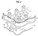
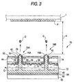
- FIGs. 2 and 3 show an ejection head that is preferably used in the aforementioned inkjet apparatus.
- an inkjet head 70 has an electroinsulative substrate 74 constituting an upper wall of an ink flow channel forming a unidirectional ink flow Q, and plural ejection parts 76 ejecting the ink to the recording medium P.
- the ejection part 76 is provided with an ink guide part 78 for guiding an ink droplet G flying from an ink flow channel 72 toward the recording medium P, and the substrate 74 has openings 75 through which the ink guide parts 78 penetrate, respectively.
- An ink meniscus 42 is formed between the ink guide part 78 and an inner wall of the opening 75.
- the gap d between the ink guide parts 78 and the recording medium P is preferably from 200 to 1, 000 mm.
- the ink guide parts 78 are fixed at the lower ends thereof to a supporting bar 40.
- the substrate 74 has an insulating layer 44 electrically insulating two ejection electrodes with a prescribed distance, a first ejection electrode 46 provided on the upper side of the insulating layer 44, an insulating layer 48 covering the first ejection electrode 46, a guard electrode 50 provided on the upper side of the insulating layer 48, and an insulating layer 52 covering the guard electrode 50.
- the substrate 74 also has a second ejection electrode 56 provided on the lower side of the insulating layer 44, and an insulating layer 58 covering the second ejection electrode 56.
- the guard electrode 50 is provided for preventing the adjacent ejection parts from being affected by a voltage applied to the first ejection electrode 46 and the second ejection electrode 56.
- the inkjet head 70 also has a floating electroconductive plate 62 constituting a bottom surface of the ink flowing channel 72, and the floating electroconductive plate 62 electrophoreses the positively charged ink particles (charged particles) in the ink flowing channel 72 upward (i.e., toward the recording medium) with an induced voltage steadily generated by a pulsewise injection voltage applied to the first ejection electrode 46 and the second ejection electrode 56.
- the floating electroconductive plate 62 has formed on the surface thereof an electroinsulative coating film 64 for preventing the physical property and the composition of the ink from being destabilized due to charge injection into the ink.
- the electroinsulative film preferably has an electric resistance of 10 12 ⁇ cm or more, and more preferably 10 13 ⁇ cm or more.
- the electroinsulative film is preferably corrosion resistant to the ink, whereby the floating electroconductive plate 62 being corroded by the ink.
- the floating electroconductive plate 62 is covered from underneath with an insulating member 66. According to the constitution, the floating electroconductive plate 62 is in a completely electroinsulative state.
- At least one of the floating electroconductive plate 62 is provided on each of the unit heads.
- the unit heads each has at least one of the floating electroconductive plate, and the unit heads C and M, for example, do not have one floating electroconductive plate in common.
- a prescribed voltage for example, +100 V
- a positive voltage is applied to the first ejection electrode 46, the second ejection electrode 56 and the recording medium P to form such a flying electric field, among the first ejection electrode 46, the second ejection electrode 56 and the recording medium P, that the positive charged particles R in the ink droplets G flying from the opening 75 as guided with the ink guide part 78 are attracted by the recording medium P.
- the voltage may be such an extent that forms a potential difference of about from 1 to 3.0 kV.
- a pulsewise voltage is applied to the first ejection electrode 46 and the second ejection electrode 56 according to the image signal, and thus the ink droplets G with an increased charge particle concentration are ejected from the opening 75.
- the initial charged particle concentration is from 3 to 15%
- the charged particle concentration of the ink droplets G is 30% or more.
- the voltage applied to the first ejection electrode 46 and the second ejection electrode 56 is adjusted in such a manner that the ink droplets G are ejection only upon applying the pulsewise voltage is applied to both the first ejection electrode 46 and the second ejection electrode 56.
- the ink droplets G fly from the opening 75 as guided by the ink guide part 78 to attach on the recording medium P, and at the same time, a positive induction voltage is generated in the floating electroconductive plate 62 by the positive voltage applied to the first ejection electrode 46 and the second ejection electrode 56.
- the induction voltage is a substantially steady voltage. Therefore, the positively charged particles R in the ink flowing channel 72 receive a force of transferring them upward by the electric field formed among the floating electroconductive plate 62, the guard electrode 50 and the recording medium P, whereby the concentration of the charged particles R is increased in the vicinity of the substrate 74.
- the number of the ejection parts i.e., channels for ejecting ink droplets
- the number of charged particles required for ejection is also increased.
- the numbers of the first ejection electrodes 46 and the second ejection electrodes 56 are also increased to generate a higher induction voltage in the floating electroconductive plate 62, whereby the number of the charged particles R moving toward the recording medium is thus increased.
- the colored particles may be negatively charged.
- the charging polarities are all inverted.
- the ink is fixed by an appropriate heating means.
- the heating means used include a contact heating device, such as a heating roller, a heating block and a heating belt, and a non-contact heating device, such as a dryer, an infrared ray lamp, a visible ray lamp, an ultraviolet ray lamp and a hot air oven.
- the heating device is preferably provided continuously to the inkjet recording apparatus and integrated thereto.
- the temperature of the recording medium upon fixing is preferably from 40 to 200°C from the standpoint of easiness of fixation.
- the period of time for fixing is preferably from 1 msec to 20 seconds.
- the charged particles in the ink composition is concentrated and ejected. Therefore, the amount of the charged particles in the ink composition is reduced after ejecting the ink composition for a long period of time to lower the electroconductivity of the ink composition.
- the ratio of the electroconductivity of the charged particles and the electroconductivity of the ink composition is also changed. Furthermore, there is such a tendency that the charged particles having larger diameters are ejected before the charged particles having smaller diameter, and thus the average particle diameter of the charged particles is decreased.
- the content of the solid matters in the ink composition is changed to vary the viscosity thereof.
- the changes in physical properties of the ink composition result in ejection failure, and decrease in optical density and blur in an image thus recorded. Accordingly, an ink composition having a higher concentration (a higher concentration of solid matters) than the ink composition initially charged in the ink tank is replenished to prevent the amount of the charged particles from being decreased, whereby the electroconductivity of the ink composition and the ratio of the electroconductivity of the charged particles and the electroconductivity of the ink composition can be maintained within certain ranges. The average particle diameter and the viscosity can also be maintained. Furthermore, the physical properties of the ink composition are maintained within certain ranges, whereby the ink composition can be ejected uniformly for a long period of time.
- the replenishment is preferably carried out by machines or by humans after the physical properties of the ink composition, such as the electroconductivity and the optical density, are detected to calculate the necessary replenishing amount.
- the replenishment may also be carried out by machines or by humans after the amount of the ink composition is calculated based on the image data.
- a printed matter can be directly obtained by inkjet recording on paper, a plastic film, a metal, paper having plastics or a metal laminated or deposited thereon, or a plastic film having a metal laminated or deposited thereon.
- An offset printing plate can be obtained by using a metallic support, such as aluminum, having a roughened surface.
- a flexographic printing plate and a color filter for a liquid crystal display can be obtained by using a plastic support.
- the recording medium may have a flat shape, such as a sheet form, or a stereoscopic shape, such as a cylindrical form.
- the invention can also be applied to production of a semiconductor and a printed circuit board by using a silicon wafer and a circuit board as the recording medium.
- an image recorded product having a high image density and high image quality without blur of ink can be stably obtained for a long period of time.
- the resulting polymer had a weight average molecular weight of 36, 000 and a melting point (Tm) of 80°C.
- the resulting polymer had a weight average molecular weight of 10, 000 and a melting point (Tm) of 63°C.
- the resulting polymer had a weight average molecular weight of 19, 000 and a melting point (Tm) of 75°C.
- the resulting polymer had a weight average molecular weight of 22, 000 and a melting point (Tm) of 70°C.
- the resulting polymer had a weight average molecular weight of 10,000 and a melting point (Tm) of 77°C.
- the resulting polymer had a weight average molecular weight of 44, 000 and a melting point (Tm) of 55°C.
- the resulting polymer had a weight average molecular weight of 28, 000 and a melting point (Tm) of 62°C.
- the resulting polymer had a weight average molecular weight of 14, 000 and a melting point (Tm) of 75°C.
- Example 1 The following materials were used in Example 1.
- the chemical structures of the coating material AP-1, the dispersing agent BZ-2 and the charge controlling agent CT-1 are shown below.
- the coating material AP-1 was obtained in the following manner. Styrene, 4-methylstyrene, butyl acrylate, dodecyl methacrylate and 2-(N,N-dimethylamino)ethyl methacrylate were subjected to radical polymerization with a known polymerization initiator, and the resulting polymer was then reacted with methyl tosylate.
- the coating material AP-1 had a weight average molecular weight of 15,000, a polydispersion degree (weight average molecular weight/number average molecular weight) of 2.7, a glass transition point (mid-point) of 51°C, and a softening point measured by a strain gauge of 46°C.
- the dispersing' agent BZ-2 was obtained in the following manner. Stearyl methacrylate was polymerized in the presence of 2-mercaptoethanol, and the resulting polymer was then reacted with methacryl anhydride to obtain a stearyl methacrylate polymer having methacryloyl groups at ends thereof (having a weight average molecular weight of 7,600). The polymer was subjected to radical polymerization with styrene to obtain the dispersing agent BZ-2, which had a weight average molecular weight of 110,000.
- the charge controlling agent CT-1 was obtained by reacting a copolymer of 1-octadecene and maleic anhydride with 1-hexadecylamine.
- the charge controlling agent CT-1 had a weight average molecular weight of 17,000.
- the ink composition EC-1 of Example 1 was charged in an ink tank of an inkjet recording apparatus having the structure shown in Figs. 1 to 3.
- the ejection head used was a 833 channel head of 150 dpi (three rows having a channel density of 50 dpi staggeredly arranged) having the structure shown in Fig. 2, and the fixing means was a heat roller formed with silicone rubber having a 1 kW heater contained therein.
- An immersion heater and stirring blades were provided as the ink temperature controlling means inside the ink tank, and the ink temperature was set at 30°C, which was controlled with a thermostat by rotating the stirring blades at 30 rpm.
- the stirring blades were also used as a stirring means for preventing precipitation and aggregation.
- a part of the ink flowing channel was made transparent, between which an LED light emission device and a photodetector device were provided, and the concentration of the ink composition was controlled based on the output signals therefrom by adding an ink diluting fluid (Isopar G) or a concentrated ink composition (which had twice the concentration of the ink composition initially charged). Fine coated paper for offset printing was used as the recording medium. After removing dusts on the surface of the recording medium by suction with an air pump, the ejection head was moved to the image forming position closely to the recording medium.
- Isopar G ink diluting fluid
- a concentrated ink composition which had twice the concentration of the ink composition initially charged
- Image data to be recorded was sent to the image data operating and controlling part, and the ink composition was successively ejected by driving the ejection head while the recording medium was conveyed through rotation of the conveying belt, so as to form an image with a drawing resolution of 2, 400 dpi.
- the conveying belt used was a belt obtained by laminating a metallic belt and a polyimide film, and a linear marker was provided in the conveying direction near one end of the belt.
- the marker was optically read by a conveying belt position detecting means, and the position controlling means was driven accordingly to attain image formation.
- the distance between the ejection head and the recording medium detected by an optical gap detecting device was maintained at 0.5 mm.
- the surface potential of the recording medium upon ejection was set at -1.5 kV, and a pulse voltage of +500 V (with a pulse width of 50 msec) was applied upon ejection to attain image formation with a driving frequency of 15 kHz.
- the resulting gray scale image recorded product (printed matter) had an extremely sharp image without stripe unevenness or ink blur. Image formation failure was completely not observed, and image deterioration due to change in dot diameter or the like was not observed even upon change in outer temperature and increase in recording duration, so as to enable image formation in good conditions.
- the image thus formed was immediately fixed by using a heating roller with the temperature of the coated paper upon fixing being varied from 60 to 100°C by 5°C, and the temperature where the coating material flowed (flow starting temperature) and the maximum temperature where offset to the heating roller did not occur (maximum offset resistant temperature) were used as standards for evaluation of fixation.
- the results obtained are shown in Table 1.
- the flow starting temperature was evaluated by observing an SEM micrograph of an image surface after fixing.
- the maximum offset resistant temperature was evaluated by offset occurring on the heating roller, which was evaluated by visually observing an image offset on the heating roller after transferring the offset image to paper.
- the blocking property of the printed image was evaluated in such a manner that an image was formed on printing paper at a fixing temperature satisfying fixing property, on which the same paper as the printing paper was superimposed and applied with a load of about 50 g/cm 2 at 50°C for 24 hours, and the extent of transfer of the image part to the superimposed paper was visually observed.
- the flow starting temperature and the maximum offset resistant temperature were also measured in the same manner as in the foregoing under such a state that the solvent remained on the recording medium (coated paper) to evaluate the fixing property.
- An ink composition EC-2 was produced by using the same materials in the same manner as in Example 1 except that the coating material AP-1 was changed to polyester, Vylon 220, produced by Toyobo, Co., Ltd.
- the ink composition EC-2 was subjected to the inkjet image formation, the evaluation of fixing property and the evaluation of antiblocking property in the same manner as in Example 1. The results obtained are shown in Table 1.
- An ink composition EC-3 was produced by using the same materials in the same manner as in Example 1 except that the coating material AP-1 was changed to a crystalline polymer 3.
- the ink composition EC-3 was subjected to the inkjet image formation, the evaluation of fixing property and the evaluation of antiblocking property in the same manner as in Example 1. The results obtained are shown in Table 1.
- An ink composition RC-1 was produced by using the same materials in the same manner as in the production for the ink composition EC-1 of Example 1 except that the crystalline polymer 1 was not added.
- the ink composition RC-1 was subjected to the inkjet image formation, the evaluation of fixing property and the evaluation of antiblocking property in the same manner as in Example 1. The results obtained are shown in Table 1.
- An ink composition RC-2 was produced by using the same materials in the same manner as in the production for the ink composition EC-1 of Example 1 except that the coating material AP-1 was changed to polymethyl methacrylate (Mw: 50,000, Tg: 10°C), and the crystalline polymer 1 was not added.
- the ink composition RC-2 was subjected to the inkjet image formation, the evaluation of fixing property and the evaluation of antiblocking property in the same manner as in Example 1. The results obtained are shown in Table 1.
- the melting point (Tm) of the crystalline polymer was a value calculated from an endothermic peak measured by a DSC.
- the evaluation standard of the fixing property was as follows.
- the evaluation standard of the antiblocking property was as follows.
- Comparative Example 1 on the other hand, the fixable temperature was difficult to be lowered only with the coating material ordinarily used, and'in the case where the recording paper contained the solvent remaining, i.e., the coating material was liable to flow, offset was liable to occur to fail to satisfy the fixing property.
- the fixable temperature could be lowered by lowering the Tg of the coating material ordinarily used, but simultaneously, the antiblocking property and the offset resistance were deteriorated to fail to satisfy the target fixing property.
- Ink compositions EC-4 to EC-22 were produced in the same manner as in the production for the ink composition EC-1 of Example 1 except that the kind and the addition amount of the crystalline polymer and the addition amount of the coating material AP-1 were changed to those shown in Tables 2 and 3 below.
- the resulting ink compositions EC-4 to EC-22 were evaluated in the same manner as in Example 1. It was understood, as a result, that the addition of the crystalline polymer having a melting point (Tm) lowered the fixable temperature and simultaneously satisfied the antiblocking property.
- Tm melting point
- such an ink composition and an inkjet recording method are provided that are capable of fixing an image with high quality to a recording medium at a low temperature with high speed.
- the polymer having a melting point (Tm) is melted sharply with respect to temperature (sharp melt property) to attain sharp melt property with anti-blocking property maintained, whereby an image can be fixed at a low temperature with high speed to provide an image with high quality.
Landscapes
- Chemical & Material Sciences (AREA)
- Life Sciences & Earth Sciences (AREA)
- Engineering & Computer Science (AREA)
- Materials Engineering (AREA)
- Wood Science & Technology (AREA)
- Organic Chemistry (AREA)
- Inks, Pencil-Leads, Or Crayons (AREA)
- Ink Jet (AREA)
- Ink Jet Recording Methods And Recording Media Thereof (AREA)
Abstract
Description
- The present invention relates to an ink composition and an inkjet recording method, and more particularly, it relates to an ink composition and an inkjet recording method capable of fixing an image with high quality to a recording medium at a low temperature and a high speed.
- As an image recording process of forming an image on a recording material, such as paper, based on image data signals, the electrophotographic system, the sublimation or melting thermal transfer system and the inkjet system have been conventionally known. Among these, the electrophotographic system requires such a process that an electrostatic latent image is formed on a photoreceptor drum through charging or exposure to necessitate a complex system, and an apparatus therefor is expensive. The thermal transfer system involves a high running cost and problems, such as formation of waste materials, due to the use of an ink ribbon, although an apparatus therefor itself is inexpensive in comparison to the electrophotographic system. In the inkjet system, on the other hand, image formation is carried out with an inexpensive apparatus in such a manner that an ink is ejected directly to only a necessary image part on a recording material, and thereby the ink can be used efficiently to reduce the running cost. Furthermore, the inkjet system causes less noise, and is excellent as an image recording process.
- The inkjet recording system includes, for example, a system of flying ink droplets by pressure of vapor generated by heat from a heater, a system of flying ink droplets by mechanical pressure pulses generated by a piezoelectric element, and a system of flying ink droplets containing charged particles by utilizing an electrostatic field (as described in Japanese Patent No. 3,315,334 and U.S. Patent No. 6,158,844). The system of flying ink droplets with vapor or mechanical pressure cannot control the flying direction of ink droplets, and there are some cases where ink droplets are difficult to be attached accurately to desired positions on a printing media due to distortion of ink nozzles and air convection.
- On the other hand, the system utilizing an electrostatic field controls the flying direction of ink droplets with the electrostatic field to enable ink droplets to be attached desired positions, and thus has advantages that an imaged material (printed matter) with high image quality can be produced.
- As an ink composition used for the inkjet recording system utilizing an electrostatic field, an ink composition containing charged particles containing at least a colorant is generally employed (as described in JP-A-8-291267 and U.S. Patent No. 5,952,048). The ink composition containing a colorant can be formed as inks of four colors, i.e., yellow, magenta, cyan and black, by changing the colorant, and can also be formed as special color inks of gold and silver. Accordingly, the ink composition is useful for producing a color imaged material (printed matter) In order to maintain the high image quality and to produce color imaged materials (printed matters) stably, it is necessary to provide means for fixing the ink composition to paper. In the inkjet recording system, furthermore, the fixation is attained without deterioration of image quality at a low temperature with high speed under such conditions that a solvent remains in the image part and the paper, and the fixation satisfying the all the aforementioned requirements has not yet been realized.
- The invention has been made under the aforementioned circumstances, and an object thereof is to provide such ink composition and inkjet recording method that are capable of fixing an image with high quality to a recording medium at a low temperature with high speed.
- The invention includes the following constitutions.
- (1) An ink composition for electrostatic inkjet
recording, comprising:
- a dispersion medium; and
- a charged particle comprising a colorant, wherein the charged particle contains at least one polymer, and said at least one polymer includes at least one first polymer having a melting point (Tm).
- (2) The ink composition for electrostatic
inkjet recording of as described in (1) above,
wherein the melting point of said at least one first polymer is from 40 to 100°C. - (3) The ink composition for electrostatic
inkjet recording as described in (1) or (2) above,
wherein said at least one polymer includes said at least one first polymer in amount of from 5 to 100% by weight. - (4) The ink composition for electrostatic
inkjet recording as described in any of (1) to (3)
above,
wherein said at least one first polymer comprises a crystalline polyester compound. - (5) The ink composition for electrostatic
inkjet recording as described in any of (1) to (3)
above,
wherein said at least one first polymer comprises a crystalline polyethylene compound. - (6) The ink composition for electrostatic
inkjet recording as described in any of (1) to (3)
above,
wherein said at least one first polymer comprises a crystalline polyethylene glycol compound. - (7) The ink composition for electrostatic
inkjet recording as described in any of (1) to (6)
above,
wherein the charged particle further contains a coating material that coats the colorant, the coating material comprising at least one of (i) said at least one first polymer and (ii) at least one second polymer not having a melting point. - (8) The ink composition for electrostatic
inkjet recording as described in (7) above,
which has the coating material in amount of from 0.1 to 40% by weight. - (9) An method of inkjet recording comprising:
- flying an ink droplet of an ink composition by utilizing an electrostatic field, wherein the ink composition comprises:
- a dispersion medium; and
- a charged particle comprising a colorant,
-
-
- Fig. 1 is a schematic illustration showing an overall structure of an example of an inkjet recording apparatus used in the invention;
- Fig. 2 is a perspective view showing a constitution of an inkjet head of the inkjet recording apparatus in the invention (The edge of the guard electrode surrounding each ejection part is not shown for an easy understanding.); and
- Fig. 3 is a side cross sectional view, showing a distribution state of charged particles where the number of ejection parts in the inkjet head shown in Fig. 2 is large. (Correspond to the section being taken in the direction of the arrows along the line X-X in Fig. 2)
-
- The ink composition according to the invention comprises a dispersion medium and a charged particle comprising a colorant, wherein the charged particle contains at least one polymer, and said at least one polymer includes at least one polymer having a melting point (Tm)(first polymer).
- The constitutional components of the ink composition according to the invention will be described below.
- As the polymer having a melting point (Tm) constituting the ink composition according to the invention, a crystalline polymer is preferably used. Examples of the crystalline polymer include polymers, such as polyester, polyalkylene, polyalkylene oxide, polyamide, polyimide, polyurethane, polyurea, polystyrene, an acrylic resin, an epoxy resin, polyamine, polyketone, polyvinyl alcohol and polyvinyl ether, and preferred examples thereof include polyester, polyalkylene, polyalkylene oxide, polyamide, polyimide, polyurethane, polyurea, polystyrene, an acrylic resin and an epoxy resin. Among these, polyester, polyethylene, polyethylene oxide (including a polyethylene glycol compound), polyamide, polyimide, polyurethane and polyurea are particularly preferably used.
- The polymer having a melting point (Tm) preferably has a melting point (Tm) of from 40 to 100°C, more preferably from 40 to 95°C, and further preferably from 50 to 90°C. The fixing property of an image is further improved in this range of the melting point (Tm).
- The melting point (Tm) referred herein means a peak temperature of an endothermic peak in a DSC measurement. In the invention, DSC TA3000 (produced by METTLER TOLEDO International Inc.) is used as a measuring apparatus, and the measurement of melting point (Tm) is carried out at a temperature increasing rate of 10°C per minute in a temperature range of from -90 to 150°C.
- In the invention, said at least one polymer includes said at least one polymer having a melting point (Tm) in amount of from 5 to 100% by weight, more preferably from 10 to 100% by weight, and further preferably from 10 to 80% by weight.
- The polymer having a melting point (Tm) preferably has a weight average molecular weight Mw of from 5,000 to 100,000.
- The dispersion medium used in the ink composition according to the invention is preferably a dielectric liquid having a high electric resistivity, specifically 1010 Ω·cm or more. A dispersion medium having a low electric resistivity is not suitable for this embodiment of the invention since such a dispersion medium causes electric conduction between recording electrodes adjacent to each other. The dielectric liquid preferably has a dielectric constant of 5 or less, more preferably 4 or less, and further preferably 3.5 or less. The use of a dielectric liquid having a dielectric constant in the range is preferred since an electric filed is efficiently applied to the charged particles in the dielectric liquid.
- Examples of the dispersion medium used in the invention include a linear or branched aliphatic hydrocarbon, an alicyclic hydrocarbon, an aromatic hydrocarbon, halogen-substituted products of these hydrocarbons, and a silicone oil. Specific examples thereof include hexane, heptane, octane, isooctane, decane, isodecane, decalin, nonane, dodecane, isododecane, cyclohexane, cyclooctane, cyclodecane, toluene, xylene, mesitylene, Isopar C, Isopar E, Isopar G, Isopar H, Isopar L and Isopar M ("Isopar" is a trade name of Exxon Chemical Corp.),
Shellsol 70 and Shellsol 71 ("Shellsol" is a trade name of Shell Oil Co.), Amsco OMS and Amsco 460 solvents ("Amsco" is a trade name of American Mineral Spirits Corp.), and KF-96L (a trade name of Shin-Etsu Silicone Co., Ltd.), which may be used solely or in combination as a mixture. The content of the dispersion medium in the ink composition is preferably from 20 to 99% by weight. The particles containing a colorant can be dispersed in the dispersion medium in good conditions with the content of the dispersion medium of 20% by weight or more, and the content of a colorant is sufficient with the content of the dispersion medium of 99% by weight or less. - Known dyes and pigments can be used as the colorant used in the ink composition according to the invention, and can be appropriately selected depending on purposes and targets. For example, a pigment is preferably used from the standpoint of color tone of an imaged material (printed matter) thus recorded (as described, for example, in "Ganryo Bunsan Anteika to Hyomen Shori Gijutu Hyoka" (Pigment Dispersion Stabilization and Surface Treatment Technique and Evaluation), published by Gijutsu Joho Kyokai Co., Ltd. on December 25, 2001 (First Issue), which is hereinafter sometimes referred to as Non-patent Document 1). Inks of four colors, i.e., yellow, magenta, cyan and black, can be produced by changing the colorant. In particular, pigments that are used in an offset printing ink and for proofing are preferably used since color tones equivalent to an offset printed matter can be obtained.
- Examples of a pigment for a yellow ink include a monoazo pigment, such as C.I. Pigment Yellow 1 and C.I. Pigment Yellow 74, a disazo pigment, such as C.I. Pigment Yellow 12 and C.I. Pigment Yellow 17, a non-benzidine azo pigment, such as C.I. Pigment Yellow 180, an azo lake pigment, such as C.I. Pigment Yellow 100, a condensed azo pigment, such as C.I. Pigment Yellow 95, an acidic dye lake pigment, such as C.I. Pigment Yellow 15, a basic dye lake pigment, such as C.I. Pigment Yellow 18, an anthraquinone pigment, such as Flavanthrone Yellow, an isoindolinone pigment, such as Isoindolinone Yellow 3RLT, a quinophthalone pigment, such as Quinophthalone Yellow, an isoindoline pigment, such as Isoindoline Yellow, a nitroso pigment, such as C.I. Pigment Yellow 153, a metallic complex azomethine pigment, such as C.I. Pigment Yellow 117, and an isoindolinone pigment, such as C.I. Pigment Yellow 139.
- Examples of a pigment for a magenta ink include a monoazo pigment, such as C.I.
Pigment Red 3, a disazo pigment, such as C.I.Pigment Red 38, an azo lake pigment, such as C.I. Pigment Red 53:1 and C.I. Pigment Red 57:1, a condensed azo pigment, such as C.I. Pigment Red 144, an acidic dye lake pigment, such as C.I. Pigment Red 174, a basic dye lake pigment, such as C.I. Pigment Red 81, an anthraquinone pigment, such as C.I. Pigment Red 177, a thioindigo pigment, such as C.I. Pigment Red 88, a perynone pigment, such as C.I. Pigment Red 194, a perylene pigment, such as C.I. Pigment Red 149, a quinacridone pigment, such as C.I. Pigment Red 122, an isoindolinone pigment, such as C.I. Pigment Red 180, and an alizarin lake pigment, such as C.I. Pigment Red 83. - Examples of a pigment for a cyan ink include a disazo pigment, such as C.I. Pigment Blue 25, a phthalocyanine pigment, such as C.I.
Pigment Blue 15, an acidic dye lake pigment, such as C.I. Pigment Blue 24, a basic dye lake pigment, such as C.I. Pigment Blue 1, an anthraquinone pigment, such as C.I. Pigment Blue 60, and an alkali blue pigment, such as C.I.Pigment Blue 18. - Examples of a pigment for a black ink include an organic pigment, such as an aniline black pigment, an iron oxide pigment, and a carbon black pigment, such as furnace black, lamp black, acetylene black and channel black.
- A processed pigment represented by a Microlith pigment, such as Microlith-A, K and T, can also be preferably used. Specific examples thereof include Microlith Yellow 4G-A, Microlith Red BP-K, Microlith Blue 4G-T and Microlith Black C-T.
- Various kinds of other pigments may be used depending on necessity, such as calcium carbonate and titanium oxide as a pigment for a white ink, aluminum powder for a silver ink, and a copper alloy for a gold ink.
- It is basically preferred that only one kind of a pigment is used for one color from the standpoint of simpleness in production of ink, but in some cases, two or more kinds of inks are preferably used in combination, for example, phthalocyanine is mixed with carbon black for a black ink. The pigments may be used after subjecting to a surface treatment by a known method, such as a rosin treatment (as described in above mentioned Non-patent Document 1).
- The content of the colorant (pigment) in the total ink composition is preferably from 0.1 to 50% by weight. The pigment amount is sufficient to provide good coloration on printed matters with the content of 0.1% by weight or more, and the particles containing the colorant can be dispersed in the dispersion medium in good conditions with the content of 50% by weight or less. The content of the colorant is more preferably from 1 to 30% by weight.
- In the ink composition in the invention, it is preferred that the colorant, such as a pigment, is dispersed in the dispersion medium (formed into particles) in a state coated with a coating material, rather than the case where the colorant is directly dispersed therein (formed into particles). According to the invention, at least one polymer having a melting point (Tm) (first polymer) may be used as the coating material, and at least one polymer having no melting point (Tm) (second polymer) may also be used as the coating material. The charge owned by the colorant can be shielded by coating with the coating material, whereby desired charging characteristics can be imparted. In the invention, after attaining inkjet recording to a recording medium, an image thus recorded is fixed with heating means, such as a heat roller, upon which the coating material is melted by heat to fix the image efficiently.
- Examples of the coating material include a rosin compound, a rosin-modified phenol resin, an alkyd resin, a (meth)acrylic polymer, polyurethane, polyester, polyamide, polyethylene, polybutadiene, polystyrene, polyvinyl acetate, an acetal-modified product of polyvinyl alcohol, and polycarbonate. Among these, a polymer having a weight average molecular weight of from 2,000 to 1,000,000 and a polydispersion degree (weight average molecular weight/number average molecular weight) of from 1.0 to 5.0 is preferred from easiness in particle formation. Furthermore, a polymer having one of a softening point and a glass transition point of from 40 to 120°C is preferred from the standpoint of easiness in fixation.
- Preferred examples of the coating material used in the invention include a polymer having a unit represented by the following general formulae (1) to (4).

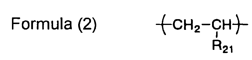


- In the formulae, X11 represents an oxygen atom or -N(R13)-; R11 represents a hydrogen atom or a methyl group; R12 represents a hydrocarbon group having from 1 to 30 carbon atoms; R13 represents a hydrogen atom or a hydrocarbon group having from 1 to 30 carbon atoms; R21 represents a hydrogen atom or a hydrocarbon group having from 1 to 20 carbon atoms; and R31, R32 and R41 each independently represents a bivalent hydrocarbon group having from 1 to 20 carbon atoms. The hydrocarbon groups represented by R12, R21, R31, R32 and R41 may contain an ether bond, an amino group, a hydroxyl group or a halogen-substituted group.
- The polymer having a unit represented by the general formula (1) can be obtained by radical polymerization of a corresponding radical polymerizable monomer by a known method. Examples of the radical polymerizable monomer include a (meth)acrylate ester, such as methyl (meth)acrylate, ethyl (meth)acrylate, propyl (meth)acrylate, butyl (meth)acrylate, hexyl (meth)acrylate, octyl (meth)acrylate, 2-ethylhexyl (meth)acrylate, dodecyl (meth)acrylate, stearyl (meth)acrylate, cyclohexyl (meth)acrylate, phenyl (meth)acrylate, benzyl (meth) acrylate and 2-hydroxyethyl (meth) acrylate, and an acrylamide, such as N-methyl(meth)acrylamide, N-propyl(meth)acrylamide, N-phenyl(meth)acrylamide and N,N-dimethyl(meth)acrylamide.
- The polymer having a unit represented by the general formula (2) can be obtained by radical polymerization of a corresponding radical polymerizable monomer by a known method. Examples of the radical polymerizable monomer include ethylene, propylene, butadiene, styrene and 4-methylstyrene.
- The polymer having a unit represented by the general formula (3) can be obtained by dehydration condensation of a corresponding dicarboxylic acid or acid anhydride with a diol by a known method. Examples of the dicarboxylic acid include succinic anhydride, adipic acid, sebacic acid, isophthalic acid, terephthalic acid, 1,4-phenylenediacetic acid and diglycolic acid. Examples of the diol include ethylene glycol, 1,2-propanediol, 1,3-propanediol, 1,4-butanediol, 1,6-hexanediol, 1,10-decanediol, 2-butene-1,4-diol, 1,4-cyclohexanediol, 1,4-cyclohexanedimethanol, 1,4-benzenedimethanol and diethylene glycol.
- The polymer having a unit represented by the general formula (4) can be obtained by dehydration condensation of a corresponding carboxylic acid having a hydroxyl group by a known method, or by ring-opening polymerization of a corresponding cyclic ester of a carboxylic acid having a hydroxyl group by a known method. Examples of the carboxylic acid having a hydroxyl group and a cyclic ester thereof include 6-hydroxyhexanoic acid, 11-hydroxyundecanoic acid, hydroxybenzoic acid and ε-caprolactone.
- The polymer having a unit represented by at least one of general formulae (1) to (4) each may be a homopolymer of the units represented by the general formulae (1) to (4), or may be a copolymer with another constitutional component. The polymers may be used as the coating material solely or in combination of two or more kinds thereof.
- Particularly preferred examples of the coating material include polyester, polyacrylate, a styrene-acrylate copolymer, polyethylene and polyurethane, and most preferably, polyester, polyacrylate, a styrene-acrylate copolymer and polyethylene.
- The content of the coating material in the total ink composition is preferably from 0.1 to 40% by weight. The amount of the coating material is sufficient to provide sufficient fixing property with the content of 0.1% by weight or more, and particles containing the colorant and the coating material can be produced in good conditions with the content of 40% by weight or less.
- In the invention, a mixture of the colorant, the polymer having a melting point (Tm) and the coating material, for example, is dispersed in the dispersing medium (formed into particles), upon which it is further preferred to use a dispersing agent for controlling the particle diameter and for preventing the particles from being precipitated.
- Preferred examples of the dispersing agent include a surface active agent represented by a sorbitan fatty acid ester, such as sorbitan monooleate, and a polyethylene glycol fatty acid ester, such as polyoxyethylene distearate. Examples thereof further include a copolymer of styrene and maleic acid and an amine-modified product thereof, a copolymer of styrene and (meth)acrylic compound, a (meth)acrylic polymer, a copolymer of ethylene and (meth)acrylic compound, rosin, BYK-160, 162, 164 and 182 (trade names of polyurethane polymers, produced by BYK Chemie GmbH), EFKA 401 and 402 (trade names of acrylic polymers, produced by EFKA Additives B.V.), and Solsperse 17000, 24000 (a trade name of a polyester polymer, by Zeneca PLC) . In the invention, such a polymer is preferably used that has a weight average molecular weight of from 1, 000 to 1, 000, 000 and a polydispersion degree (weight average molecular weight/number average molecular weight) of from 1.0 to 7.0, from the standpoint of long term storage stability of the ink composition. A graft polymer and a block polymer are most preferably used.
- Most preferred examples of the polymer used as the dispersing agent in the invention include a graft polymer containing at least a polymer component having at least one of units represented by the following general formulae (5) and (6) with a graft chain having a unit represented by the following general formula (7) :


- In the formulae, X51 represents an oxygen atom or -N(R53)-; R51 represents a hydrogen atom or a methyl group; R52 represents a hydrocarbon group having from 1 to 10 carbon atoms; R53 represents a hydrogen atom or a hydrocarbon group having from 1 to 10 carbon atoms; R61 represents a hydrogen atom, a hydrocarbon group having from 1 to 20 carbon atoms, a halogen atom, a hydroxyl group or an alkoxy group having from 1 to 20 carbon atoms; X71 represents an oxygen atom or -N(R73)-; R71 represents a hydrogen atom or a methyl group; R72 represents a hydrocarbon group having from 4 to 30 carbon atoms; and R73 represents a hydrogen atom or a hydrocarbon group having from 1 to 30 carbon atoms . The hydrocarbon groups represented by R52 and R72 may contain an ether bond, an amino group, a hydroxyl group or a halogen-substituted group.
- The graft polymer can be obtained in such a manner that a radical polymerizable monomer corresponding to the general formula (7) is polymerized, preferably in the presence of a chain transfer agent, and polymerizable functional groups are introduced to ends of the resulting polymer, which is then further copolymerized with a radical polymerizable monomer corresponding to the general formula (5) or (6).
- Examples of the radical polymerizable monomer corresponding to the general formula (5) include a (meth)acrylate ester, such as methyl (meth)acrylate, ethyl (meth)acrylate, propyl (meth)acrylate, butyl (meth)acrylate, hexyl (meth)acrylate, cyclohexyl (meth)acrylate, phenyl (meth)acrylate, benzyl (meth) acrylate and 2-hydroxyethyl (meth)acrylate, and a (meth)acrylamide, such as N-methyl (meth)acrylamide, N-propyl(meth)acrylamide, N-phenyl(meth)acrylamide and N,N-dimethyl(meth)acrylamide.
- Examples of the radical polymerizable monomer corresponding to the general formula (6) include styrene, 4-methylstyrene, chlorostyrene and methoxystyrene.
- Examples of the radical polymerizable monomer corresponding to the general formula (7) include hexyl (meth)acrylate, octyl (meth)acrylate, 2-ethylhexyl (meth)acrylate, dodecyl (meth)acrylate and stearyl (meth)acrylate.
- Specific examples of the graft polymer include polymers represented by the following structural formulae.


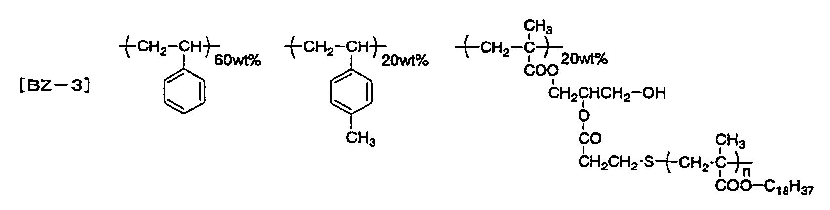

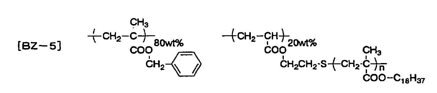

- The graft polymer containing at least a polymer component having at least one of units represented by the general formulae (5) and (6) with a graft chain having at least a unit represented by the general formula (7) may have only the units represented by the general formula(e) (5) and/or (6) and the general formula (7), and may also contain another constitutional component. The compositional ratio of the polymer component containing the graft chain and the other polymer component is preferably from 10:90 to 90:10. The range is preferred since formation of particles can be attained in good conditions, and a desired particle diameter can be easily obtained. The polymer may be used as the dispersing agent solely or in combination as a mixture.
- The content of the dispersing agent in the total amount of ink composition is preferably from 0.01 to 30% by weight. Formation of particles can be attained in good conditions, and a desired particle diameter can be obtained within the range.
- It is preferred in the invention that a mixture of the colorant, the polymer having a melting point (Tm) and the coating material is dispersed in the dispersion medium (formed into particles) by using the dispersing agent, and it is further preferred that a charge controlling agent for controlling the charge amount of the particles is used in combination.
- Preferred examples of the charge controlling agent include a metallic salt of an organic carboxylic acid, such as zirconium naphthenoate and zirconium octenoate, an ammonium salt of an organic carboxylic acid, such as tetramethyammonium stearate, a metallic salt of an organic sulfonic acid, such as sodium dodecylbenzenesulfonate and magnesium dioctylsulfosuccinate, an ammonium salt of an organic sulfonic acid, such as tetrabutylammonium toluenesulfonate, a polymer having a carboxylic acid group on a side chain, such as a polymer having a carboxylic acid group formed by modifying a copolymer of styrene and maleic anhydride with an amine, a polymer having a carboxylic anionic group on a side chain, such as a copolymer of stearyl methacrylate and tetramethyammonium methacrylate, a polymer having a nitrogen atom on a side chain, such as a copolymer of styrene and vinylpyridine, and a polymer having an ammonium group on a side chain, such as a copolymer of butyl methacrylate and N-(2-methacryloyloxyethyl)-N,N,N-trimethylammonium tosylate. The charge imparted to the particles may be positive charge or negative charge. The content of the charge controlling agent in the total ink composition is preferably from 0.0001 to 10% by weight. The ink composition according to the invention preferably has an electroconductivity of from 10 to 300 nS/m, and the charged particles preferably have an electroconductivity of 50% or more the electroconductivity of the ink composition. These conditions can be easily adjusted by changing the content of the charge controlling agent.
- In the invention, an antiseptic for preventing decay, a surface active agent for controlling the surface tension, and the like may be added depending on purposes.
- The ink composition containing the charged particles according to the invention can be produced by using the aforementioned components through dispersion (formation of particles) the colorant, the polymer having a melting point (Tm) and preferably the coating material. Examples of the method for dispersing (forming into particles) include the following methods.
- (1) The colorant, the polymer having a melting point (Tm) and preferably the coating material are mixed, and the mixture is dispersed (formed into particles) by using the dispersing agent and the dispersion medium, to which the charge controlling agent is then added.
- (2) The colorant, the polymer having a melting point (Tm), the coating material, the dispersing agent and the dispersion medium are simultaneously dispersed (formed into particles), and then the charge controlling agent is added.
- (3) The colorant, the polymer having a melting point (Tm), the coating material, the dispersing agent, the charge controlling agent and the dispersion medium are simultaneously dispersed (formed into particles).
-
- As having been described, the polymer having a melting point (Tm) can also function as the coating material.
- Examples of an apparatus for using upon mixing and dispersing include a kneader, a dissolver, a mixer, a high-speed disperser, a sand mill, a roll mill, a ball mill, an attritor and a beads mill (as described in above mentioned Non-patent Document 1).
- The ink particles (charged particles) in the invention suitably has a diameter of from 0.5 to 4 mm, preferably from 0.7 to 3.5 mm, and more preferably from 0.8 to 3 mm. The size is larger than that of the toner for the ordinary electrophotographic liquid developer (from 0.1 to 0.4 mm) and is smaller than that of the toner for the ordinary electrophotographic dry developer (from 5 to 15 mm).
- The ink composition preferably has a viscosity (20°C) of from 0. 5 to 5 mPa·s. Such problems as leakage from an ink ejection outlet of a head and ejection failure of ink droplets can be prevented within the range. The viscosity is more preferably from 0.8 to 4 mPa·s. The ink composition preferably has a surface tension of from 10 to 70 mN/m. Such problems as leakage from an ink ejection outlet of a head and ejection failure of ink droplets can be prevented within the range. The surface tension is more preferably from 15 to 50 mN/m.
- In the invention, the aforementioned ink composition is recorded on a recording medium by the inkjet recording system. It is preferred in the invention that the inkjet recording system utilizing an electrostatic field is preferably employed. In the inkjet recording system utilizing an electrostatic field, a voltage is applied between a control electrode and a back electrode on the back surface of the recording medium, whereby the charged particles in the ink composition are concentrated at an ejection position through an electrostatic force to cause the ink composition to fly from the ejection position to the recording medium. In the case where the charged particles are positively charged, for example, the voltage is applied between the control electrode as an anode and the back electrode as a cathode. The same effect can be obtained by charging the recording medium instead of application of the voltage to the back electrode.
- Examples of the method for flying an ink include a method of flying an ink from a point of a member having a needle shape, such as an injection needle, which can be used for recordation with the ink composition according to the invention. In the method, however, replenishment of the charged particles after concentration and ejection is difficult, and recordation cannot be stably attained for a long period of time. The charged particles are forcedly supplied in this method, and therefore, upon circulating the ink, the ink is overspilled from the point of the injection needle. Accordingly, the meniscus shape at the point of the injection needle as the ejection position is not stabilized to make stable recordation difficult. Therefore, the method is suitable for recordation of short-duration.
- On the other hand, such a method is preferably used that the ink composition can be circulated without spillover of the ink composition from an ejection opening. In such a method, for example, an ink is circulated in an ink chamber having an ejection opening, and an ink guide is provided in the ejection opening. A voltage is applied to a control electrode formed around the ejection opening to cause concentrated ink droplets to fly from a point of the ink guide directed to a recording medium. In this method, both replenishment of the charged particles and stabilization of the meniscus at the ejection position can be simultaneously attained by circulating the ink composition, so as to enable stable recordation for a long period of time. Furthermore, the ink is in contact with the outside air only at a significantly small area, i.e., the ejection opening, and thus the solvent can be prevented from being evaporated to stabilize the physical property of the ink composition. Accordingly, the method is preferably used in the invention.
- An example of a constitution of an inkjet recording apparatus suitable for application of the ink composition according to the invention will be described below.
- An apparatus for printing in four colors on one surface of a recording medium shown in Fig. 1 will be described.
- The inkjet recording apparatus 1 shown in Fig. 1 has an
ejection head 2 for forming full color image formation constituted by unit ejection heads 2C, 2M, 2Y and 2K for four colors, anink circulation system 3 for supplying an ink to theejection head 2 and recovering the ink from theejection head 2, ahead driver 4 for driving theejection head 2 based on output from an external device, such as a computer and RIP, which is not shown in the figure, and a position controlling means 5. The inkjet recording apparatus 1 also has a conveyingbelt 7 stretched among threerollers belt 7, an electrostatic adsorption means 9 for retaining a recording medium P on the conveyingbelt 7, and acharge eraser 10 and amechanical means 11 for releasing the recording medium P from the conveyingbelt 7 after completing image formation. A feedingroller 12 and aguide 13 for feeding the recording medium P from a paper stock, which is not shown in the figure, to the conveyingbelt 7 are disposed on the upstream side of the conveyingbelt 7, and a fixing means 14 and aguide 15 for fixing the ink on the recording medium P after releasing and conveying the recording medium P to a delivery tray, which is not shown in the figure, are disposed on the downstream side of the conveyingbelt 7. The inkjet recording apparatus 1 has thereinside a recording medium position detecting means 16 at a position opposite to the ejection head with respect to the conveyingbelt 7, and a solvent recovering part containing anexhaust fan 17 and asolvent vapor adsorbent 18 for recovering a solvent vapor generated from the ink composition, by which the solvent vapor inside the apparatus is exhausted to the exterior of the apparatus through the recovering part. - A known roller may be used as the feeding
roller 12, which is disposed to obtain improved feeding capability of the recording medium. The recording medium P often has dusts and paper powder attached thereon, which are preferably removed. The recording medium P thus fed by the feedingroller 12 is conveyed to the conveyingbelt 7 through theguide 13. The back surface (preferably a metallic back surface) of the conveyingbelt 7 is disposed through theroller 6A. The recording medium thus conveyed is electrostatically adsorbed on the conveying belt with the electrostatic adsorption means 9. In the embodiment shown in Fig. 1, electrostatic adsorption is attained by a scorotron charging device connected to a negative high voltage electric source. The recording medium P is electrostatically adsorbed on the conveyingbelt 7 without floatage and is uniformly charged over the surface of the recording medium by the electrostatic adsorption means 9. While the electrostatic adsorption means is also used as a charging means of the recording medium in this embodiment, these means may be separately provided. The recording medium P thus charged is conveyed by the conveyingbelt 7 to the position of theejection head 2, and recording signals are overlapped with the charged potential as bias to attain electrostatic inkjet image formation. The recording medium P thus having been subjected to image formation is destaticized by thecharge eraser 10 and released from the conveyingbelt 7 by themechanical means 11, followed by being conveyed to the fixing part. The recording medium P thus released is delivered to the image fixing means 14 for fixing. The recording medium P thus fixed is delivered to the delivery tray, which is not shown in the figure. The apparatus has a recovering means for recovering a solvent vapor generated from the ink composition. The recovering means has thesolvent vapor adsorbent 18. The gas containing the solvent vapor inside the apparatus is introduced to the absorbent by theexhaust fan 17, and after adsorbing and recovering the solvent vapor, the gas is exhausted to the exterior of the apparatus. The apparatus is not limited to the aforementioned embodiment, but the constitutional components and the configurations, such as the numbers, shapes, relative positions and charging polarities of the constitutional devices including the roller and the charging device, can be arbitrarily selected. Furthermore, while the four-color printing is attained in the aforementioned system, multi-color systems exceeding four colors may be constituted by combining a light-color ink and a special color ink. - The inkjet recording apparatus used in the inkjet printing system has the
ejection head 2 and theink circulation system 3. Theink circulation system 3 has an ink tank, an ink circulation device, an ink concentration controlling device, an ink temperature controlling device and the like and the ink tank may contain thereinside a stirring device. - As the
ejection head 2, a single channel head, a multi-channel head and a full-line head may be used, and main scanning is carried out by rotation of the conveyingbelt 7. - An inkjet head that can be preferably used in the invention is of such an inkjet system that the charged particles is electrophoresed in an ink flow channel to increase the ink concentration in the vicinity of the opening, so as to eject the ink, and ejects ink droplets mainly through an electrostatic attraction force caused by the recording medium or a counter electrode disposed in the back side of the recording medium. Therefore, ink droplets are not ejected in the case where the recording medium or the counter electrode faces the head and the case where no voltage is applied to the recording medium or the counter electrode even though they face the head, whereby the interior of the apparatus is prevented from being contaminated.
- Figs. 2 and 3 show an ejection head that is preferably used in the aforementioned inkjet apparatus. As shown in Figs. 2 and 3, an
inkjet head 70 has anelectroinsulative substrate 74 constituting an upper wall of an ink flow channel forming a unidirectional ink flow Q, andplural ejection parts 76 ejecting the ink to the recording medium P. Theejection part 76 is provided with anink guide part 78 for guiding an ink droplet G flying from anink flow channel 72 toward the recording medium P, and thesubstrate 74 hasopenings 75 through which theink guide parts 78 penetrate, respectively. Anink meniscus 42 is formed between theink guide part 78 and an inner wall of theopening 75. The gap d between theink guide parts 78 and the recording medium P is preferably from 200 to 1, 000 mm. Theink guide parts 78 are fixed at the lower ends thereof to a supportingbar 40. - The
substrate 74 has an insulatinglayer 44 electrically insulating two ejection electrodes with a prescribed distance, afirst ejection electrode 46 provided on the upper side of the insulatinglayer 44, an insulatinglayer 48 covering thefirst ejection electrode 46, aguard electrode 50 provided on the upper side of the insulatinglayer 48, and an insulatinglayer 52 covering theguard electrode 50. Thesubstrate 74 also has asecond ejection electrode 56 provided on the lower side of the insulatinglayer 44, and an insulatinglayer 58 covering thesecond ejection electrode 56. Theguard electrode 50 is provided for preventing the adjacent ejection parts from being affected by a voltage applied to thefirst ejection electrode 46 and thesecond ejection electrode 56. - The
inkjet head 70 also has a floatingelectroconductive plate 62 constituting a bottom surface of theink flowing channel 72, and the floatingelectroconductive plate 62 electrophoreses the positively charged ink particles (charged particles) in theink flowing channel 72 upward (i.e., toward the recording medium) with an induced voltage steadily generated by a pulsewise injection voltage applied to thefirst ejection electrode 46 and thesecond ejection electrode 56. The floatingelectroconductive plate 62 has formed on the surface thereof anelectroinsulative coating film 64 for preventing the physical property and the composition of the ink from being destabilized due to charge injection into the ink. The electroinsulative film preferably has an electric resistance of 1012 Ω·cm or more, and more preferably 1013 Ω·cm or more. The electroinsulative film is preferably corrosion resistant to the ink, whereby the floatingelectroconductive plate 62 being corroded by the ink. The floatingelectroconductive plate 62 is covered from underneath with an insulatingmember 66. According to the constitution, the floatingelectroconductive plate 62 is in a completely electroinsulative state. - At least one of the floating
electroconductive plate 62 is provided on each of the unit heads. (For example, in the case where four unit heads of C, M, Y and K are used, the unit heads each has at least one of the floating electroconductive plate, and the unit heads C and M, for example, do not have one floating electroconductive plate in common.) - In order to cause the ink to fly from the
inkjet head 70 to record on the recording medium P, as shown in Fig. 3, a prescribed voltage (for example, +100 V) is applied to theguard electrode 50 in such a state that the ink is circulated in theink flowing channel 72 to form an ink flow Q. Furthermore, a positive voltage is applied to thefirst ejection electrode 46, thesecond ejection electrode 56 and the recording medium P to form such a flying electric field, among thefirst ejection electrode 46, thesecond ejection electrode 56 and the recording medium P, that the positive charged particles R in the ink droplets G flying from theopening 75 as guided with theink guide part 78 are attracted by the recording medium P. For example, in the case where the gap d is 500 mm, the voltage may be such an extent that forms a potential difference of about from 1 to 3.0 kV. - Under the aforementioned state, a pulsewise voltage is applied to the
first ejection electrode 46 and thesecond ejection electrode 56 according to the image signal, and thus the ink droplets G with an increased charge particle concentration are ejected from theopening 75. For example, in the case where the initial charged particle concentration is from 3 to 15%, the charged particle concentration of the ink droplets G is 30% or more. - At this time, the voltage applied to the
first ejection electrode 46 and thesecond ejection electrode 56 is adjusted in such a manner that the ink droplets G are ejection only upon applying the pulsewise voltage is applied to both thefirst ejection electrode 46 and thesecond ejection electrode 56. - Upon applying the pulsewise positive voltage, the ink droplets G fly from the
opening 75 as guided by theink guide part 78 to attach on the recording medium P, and at the same time, a positive induction voltage is generated in the floatingelectroconductive plate 62 by the positive voltage applied to thefirst ejection electrode 46 and thesecond ejection electrode 56. Even in the case where the voltage applied to thefirst ejection electrode 46 and thesecond ejection electrode 56 has a pulsewise form, the induction voltage is a substantially steady voltage. Therefore, the positively charged particles R in theink flowing channel 72 receive a force of transferring them upward by the electric field formed among the floatingelectroconductive plate 62, theguard electrode 50 and the recording medium P, whereby the concentration of the charged particles R is increased in the vicinity of thesubstrate 74. In the case where the number of the ejection parts (i.e., channels for ejecting ink droplets) used is large as shown in Fig. 3, the number of charged particles required for ejection is also increased. In such a case, the numbers of thefirst ejection electrodes 46 and thesecond ejection electrodes 56 are also increased to generate a higher induction voltage in the floatingelectroconductive plate 62, whereby the number of the charged particles R moving toward the recording medium is thus increased. - While the case where the colored particles are positively charged has been described in this embodiment, the colored particles may be negatively charged. In the later case, the charging polarities are all inverted.
- It is preferred in the invention that after ejecting the ink on the recording medium, the ink is fixed by an appropriate heating means. Examples of the heating means used include a contact heating device, such as a heating roller, a heating block and a heating belt, and a non-contact heating device, such as a dryer, an infrared ray lamp, a visible ray lamp, an ultraviolet ray lamp and a hot air oven. The heating device is preferably provided continuously to the inkjet recording apparatus and integrated thereto. The temperature of the recording medium upon fixing is preferably from 40 to 200°C from the standpoint of easiness of fixation. The period of time for fixing is preferably from 1 msec to 20 seconds.
- In the inkjet recording system utilizing an electrostatic field, the charged particles in the ink composition is concentrated and ejected. Therefore, the amount of the charged particles in the ink composition is reduced after ejecting the ink composition for a long period of time to lower the electroconductivity of the ink composition. The ratio of the electroconductivity of the charged particles and the electroconductivity of the ink composition is also changed. Furthermore, there is such a tendency that the charged particles having larger diameters are ejected before the charged particles having smaller diameter, and thus the average particle diameter of the charged particles is decreased. Moreover, the content of the solid matters in the ink composition is changed to vary the viscosity thereof.
- The changes in physical properties of the ink composition result in ejection failure, and decrease in optical density and blur in an image thus recorded. Accordingly, an ink composition having a higher concentration (a higher concentration of solid matters) than the ink composition initially charged in the ink tank is replenished to prevent the amount of the charged particles from being decreased, whereby the electroconductivity of the ink composition and the ratio of the electroconductivity of the charged particles and the electroconductivity of the ink composition can be maintained within certain ranges. The average particle diameter and the viscosity can also be maintained. Furthermore, the physical properties of the ink composition are maintained within certain ranges, whereby the ink composition can be ejected uniformly for a long period of time. The replenishment is preferably carried out by machines or by humans after the physical properties of the ink composition, such as the electroconductivity and the optical density, are detected to calculate the necessary replenishing amount. The replenishment may also be carried out by machines or by humans after the amount of the ink composition is calculated based on the image data.
- In the invention, various kinds of recording media may be used depending on purposes. For example, a printed matter can be directly obtained by inkjet recording on paper, a plastic film, a metal, paper having plastics or a metal laminated or deposited thereon, or a plastic film having a metal laminated or deposited thereon. An offset printing plate can be obtained by using a metallic support, such as aluminum, having a roughened surface. A flexographic printing plate and a color filter for a liquid crystal display can be obtained by using a plastic support. The recording medium may have a flat shape, such as a sheet form, or a stereoscopic shape, such as a cylindrical form. The invention can also be applied to production of a semiconductor and a printed circuit board by using a silicon wafer and a circuit board as the recording medium.
- According to combinations of the ink composition, the inkjet recording apparatus and the replenishment of the ink composition, an image recorded product having a high image density and high image quality without blur of ink can be stably obtained for a long period of time.
- The invention will be described in more detail with reference to the following examples, but the invention is not construed as being limited thereto.
- 70.8 parts by weight of sebacic acid (produced by Wako Pure Chemical Industries, Ltd.), 61 parts by weight of 1,10-decanediol (produced by Wako Pure Chemical Industries, Ltd.), 161 parts by weight of xylene (produced by Wako Pure Chemical Industries, Ltd.) and 0.67 part by weight of p-toluenesulfonic acid monohydrate (produced by Wako Pure Chemical Industries, Ltd.) were placed in a three-neck flask and refluxed over an oil bath to react them by the azeotropic dehydration method for 8 hours. Thereafter, the reaction mixture was cooled to room temperature. The reaction mixture was then placed in 3 L of methanol to purify by reprecipitation, followed by drying in vacuum, to obtain about 110 g of crystalline polyester.
- The resulting polymer had a weight average molecular weight of 36, 000 and a melting point (Tm) of 80°C.
- 44.15 parts by weight of adipic acid (produced by Wako Pure Chemical Industries, Ltd.), 41.36 parts by weight of 1,6-hexanediol (produced by Wako Pure Chemical Industries, Ltd.), 105 parts by weight of xylene (produced by Wako Pure Chemical Industries, Ltd.) and 0.67 part by weight of p-toluenesulfonic acid monohydrate (produced by Wako Pure Chemical Industries, Ltd.) were placed in a three-neck flask and refluxed over an oil bath to react them by the azeotropic dehydration method for 8 hours. Thereafter, the reaction mixture was cooled to room temperature. The reaction mixture was then placed in 3 L of methanol to purify by reprecipitation, followed by drying in vacuum, to obtain about 75 g of crystalline polyester.
- The resulting polymer had a weight average molecular weight of 10, 000 and a melting point (Tm) of 63°C.
- 70.8 parts by weight of sebacic acid (produced by Wako Pure Chemical Industries, Ltd.), 40.66 parts by weight of 1, 4-cyclohexanediol (produced by Wako Pure Chemical Industries, Ltd.), 137 parts by weight of xylene (produced by Wako Pure Chemical Industries, Ltd.) and 0.67 part by weight of p-toluenesulfonic acid monohydrate (produced by Wako Pure Chemical Industries, Ltd.) were placed in a three-neck flask and refluxed over an oil bath to react them by the azeotropic dehydration method for 8 hours. Thereafter, the reaction mixture was cooled to room temperature. The reaction mixture was then placed in 3 L of methanol to purify by reprecipitation, followed by drying in vacuum, to obtain about 100 g of crystalline polyester.
- The resulting polymer had a weight average molecular weight of 19, 000 and a melting point (Tm) of 75°C.
- 70.8 parts by weight of sebacic acid (produced by Wako Pure Chemical Industries, Ltd.), 31.54 parts by weight of 1,4-butanediol (produced by Wako Pure Chemical Industries, Ltd.), 126 parts by weight of xylene (produced by Wako Pure Chemical Industries, Ltd.) and 0.67 part by weight of p-toluenesulfonic acid monohydrate (produced by Wako Pure Chemical Industries, Ltd.) were placed in a three-neck flask and refluxed over an oil bath to react them by the azeotropic dehydration method for 8 hours. Thereafter, the reaction mixture was cooled to room temperature. The reaction mixture was then placed in 3 L of methanol to purify by reprecipitation, followed by drying in vacuum, to obtain about 94 g of crystalline polyester.
- The resulting polymer had a weight average molecular weight of 22, 000 and a melting point (Tm) of 70°C.
- 40 parts by weight of succinic anhydride (produced by Wako Pure Chemical Industries, Ltd.), 30 parts by weight of 1,3-propanediol (produced by Wako Pure Chemical Industries, Ltd.), 90 parts by weight of toluene (produced by Wako Pure Chemical Industries, Ltd.) and 0.76 part by weight of p-toluenesulfonic acid monohydrate (produced by Wako Pure Chemical Industries, Ltd.) were placed in a three-neck flask and refluxed over an oil bath to react them by the azeotropic dehydration method for 8 hours. Thereafter, the reaction mixture was cooled to room temperature. The reaction mixture was then placed in 3 L of methanol to purify by reprecipitation, followed by drying in vacuum, to obtain about 60 g of crystalline polyester.
- The resulting polymer had a weight average molecular weight of 10,000 and a melting point (Tm) of 77°C.
- 70.8 parts by weight of sebacic acid (produced by Wako Pure Chemical Industries, Ltd.), 50.47 parts by weight of 1,4-cyclohexanedimethanol (produced by Wako Pure Chemical Industries, Ltd.), 149 parts by weight of xylene (produced by Wako Pure Chemical Industries, Ltd.) and 0. 67 part by weight of p-toluenesulfonic acid monohydrate (produced by Wako Pure Chemical Industries, Ltd.) were placed in a three-neck flask and refluxed over an oil bath to react them by the azeotropic dehydration method for 8 hours. Thereafter, the reaction mixture was cooled to room temperature. The reaction mixture was then placed in 3 L of methanol to purify by reprecipitation, followed by drying in vacuum, to obtain about 120 g of crystalline polyester.
- The resulting polymer had a weight average molecular weight of 44, 000 and a melting point (Tm) of 55°C.
- 60.7 parts by weight of sebacic acid (produced by Wako Pure Chemical Industries, Ltd.), 18.02 parts by weight of 1,4-butanediol (produced by Wako Pure Chemical Industries, Ltd.), 6.37 parts by weight of 2-hydroxy-1,4-butanediol, 126 parts by weight of xylene (produced by Wako Pure Chemical Industries, Ltd.) and 0.67 part by weight of p-toluenesulfonic acid monohydrate (produced by Wako Pure Chemical Industries, Ltd.) were placed in a three-neck flask and refluxed over an oil bath to react them by the azeotropic dehydration method for 8 hours. Thereafter, the reaction mixture was cooled to room temperature. The reaction mixture was then placed in 3 L of methanol to purify by reprecipitation, followed by drying in vacuum, to obtain about 78 g of crystalline polyester.
- The resulting polymer had a weight average molecular weight of 28, 000 and a melting point (Tm) of 62°C.
- 44.15 parts by weight of adipic acid (produced by Wako Pure Chemical Industries, Ltd.), 27.23 parts by weight of p-xylylene glycol (produced by Tokyo Kasei Kogyo Co., Ltd.), 105 parts by weight of xylene (produced by Wako Pure Chemical Industries, Ltd.) and 0.67 part by weight of p-toluenesulfonic acid monohydrate (produced by Wako Pure Chemical Industries, Ltd.) were placed in a three-neck flask and refluxed over an oil bath to react them by the azeotropic dehydration method for 8 hours. Thereafter, the reaction mixture was cooled to room temperature. The reaction mixture was then placed in 3 L of methanol to purify by reprecipitation, followed by drying in vacuum, to obtain about 62 g of crystalline polyester.
- The resulting polymer had a weight average molecular weight of 14, 000 and a melting point (Tm) of 75°C.
- The following materials were used in Example 1.
- Cyan pigment (colorant) : phthalocyanine pigment, C.I. Pigment Blue (15:3) (Lionol Blue FG-7350, produced by Toyo Ink Mfg. Co., Ltd.)
- Coating material: AP-1
- Crystalline polymer 1
- Dispersing agent: BZ-2
- Charge controlling agent: CT-1
- Dispersion medium: Isopar G (produced by Exxon Chemical Corp.)
-
- The chemical structures of the coating material AP-1, the dispersing agent BZ-2 and the charge controlling agent CT-1 are shown below.



- The coating material AP-1 was obtained in the following manner. Styrene, 4-methylstyrene, butyl acrylate, dodecyl methacrylate and 2-(N,N-dimethylamino)ethyl methacrylate were subjected to radical polymerization with a known polymerization initiator, and the resulting polymer was then reacted with methyl tosylate. The coating material AP-1 had a weight average molecular weight of 15,000, a polydispersion degree (weight average molecular weight/number average molecular weight) of 2.7, a glass transition point (mid-point) of 51°C, and a softening point measured by a strain gauge of 46°C.
- The dispersing' agent BZ-2 was obtained in the following manner. Stearyl methacrylate was polymerized in the presence of 2-mercaptoethanol, and the resulting polymer was then reacted with methacryl anhydride to obtain a stearyl methacrylate polymer having methacryloyl groups at ends thereof (having a weight average molecular weight of 7,600). The polymer was subjected to radical polymerization with styrene to obtain the dispersing agent BZ-2, which had a weight average molecular weight of 110,000.
- The charge controlling agent CT-1 was obtained by reacting a copolymer of 1-octadecene and maleic anhydride with 1-hexadecylamine. The charge controlling agent CT-1 had a weight average molecular weight of 17,000.
- 10 g of the cyan pigment, 16 g of the coating material AP-1 and 4 g of the crystalline polymer 1 were placed in a desktop kneader, PBV-0.1, produced by Irie Shokai Co., Ltd., and mixed under heating at a heater temperature set at 100°C for 2 hours. 30 g of the mixture thus obtained was coarsely pulverized in a trio blender, produced by Trio Science Co., Ltd., and then finely pulverized in a sample mill, Model SK-M10, produced by Kyoritu Riko Co., Ltd. 30 g of the finely pulverized product thus obtained was preliminary dispersed in a paint shaker, produced by Toyo Seiki Co., Ltd., along with 7.5 g of the dispersing agent BZ-2, 75 g of Isopar G and glass beads having a diameter of about 3.0 mm. After removing the glass beads, the mixture was further dispersed (formed into particles) along with zirconia ceramic beads having a diameter of about 0.6 mm in a Dinor mill, Type KDL, produced by Shinmaru Enterprises Co., Ltd., for 5 hours at an inner temperature maintained at 25°C and for further 5 hours at 45°C, at a rotation number of 2,000 rpm. The zirconia ceramic beads were removed from the resulting dispersion liquid, to which 316 g of Isopar G and 0.6 g of the charge controlling agent CT-1 were added, to obtain an ink composition EC-1.
- The ink composition EC-1 of Example 1 was charged in an ink tank of an inkjet recording apparatus having the structure shown in Figs. 1 to 3. The ejection head used was a 833 channel head of 150 dpi (three rows having a channel density of 50 dpi staggeredly arranged) having the structure shown in Fig. 2, and the fixing means was a heat roller formed with silicone rubber having a 1 kW heater contained therein. An immersion heater and stirring blades were provided as the ink temperature controlling means inside the ink tank, and the ink temperature was set at 30°C, which was controlled with a thermostat by rotating the stirring blades at 30 rpm. The stirring blades were also used as a stirring means for preventing precipitation and aggregation. A part of the ink flowing channel was made transparent, between which an LED light emission device and a photodetector device were provided, and the concentration of the ink composition was controlled based on the output signals therefrom by adding an ink diluting fluid (Isopar G) or a concentrated ink composition (which had twice the concentration of the ink composition initially charged). Fine coated paper for offset printing was used as the recording medium. After removing dusts on the surface of the recording medium by suction with an air pump, the ejection head was moved to the image forming position closely to the recording medium. Image data to be recorded was sent to the image data operating and controlling part, and the ink composition was successively ejected by driving the ejection head while the recording medium was conveyed through rotation of the conveying belt, so as to form an image with a drawing resolution of 2, 400 dpi. The conveying belt used was a belt obtained by laminating a metallic belt and a polyimide film, and a linear marker was provided in the conveying direction near one end of the belt. The marker was optically read by a conveying belt position detecting means, and the position controlling means was driven accordingly to attain image formation. The distance between the ejection head and the recording medium detected by an optical gap detecting device was maintained at 0.5 mm. The surface potential of the recording medium upon ejection was set at -1.5 kV, and a pulse voltage of +500 V (with a pulse width of 50 msec) was applied upon ejection to attain image formation with a driving frequency of 15 kHz.
- The resulting gray scale image recorded product (printed matter) had an extremely sharp image without stripe unevenness or ink blur. Image formation failure was completely not observed, and image deterioration due to change in dot diameter or the like was not observed even upon change in outer temperature and increase in recording duration, so as to enable image formation in good conditions.
- The image thus formed was immediately fixed by using a heating roller with the temperature of the coated paper upon fixing being varied from 60 to 100°C by 5°C, and the temperature where the coating material flowed (flow starting temperature) and the maximum temperature where offset to the heating roller did not occur (maximum offset resistant temperature) were used as standards for evaluation of fixation.
- That is, such an ink composition is desired that the flow starting temperature is attained at a lower temperature, and offset does not occur until a higher temperature. The term "flowing" referred herein means such a state that the coating material is melted and formed into a film after flowing.
- The results obtained are shown in Table 1. The flow starting temperature was evaluated by observing an SEM micrograph of an image surface after fixing.
- The maximum offset resistant temperature was evaluated by offset occurring on the heating roller, which was evaluated by visually observing an image offset on the heating roller after transferring the offset image to paper.
- The blocking property of the printed image was evaluated in such a manner that an image was formed on printing paper at a fixing temperature satisfying fixing property, on which the same paper as the printing paper was superimposed and applied with a load of about 50 g/cm2 at 50°C for 24 hours, and the extent of transfer of the image part to the superimposed paper was visually observed.
- The flow starting temperature and the maximum offset resistant temperature were also measured in the same manner as in the foregoing under such a state that the solvent remained on the recording medium (coated paper) to evaluate the fixing property.
- An ink composition EC-2 was produced by using the same materials in the same manner as in Example 1 except that the coating material AP-1 was changed to polyester, Vylon 220, produced by Toyobo, Co., Ltd. The ink composition EC-2 was subjected to the inkjet image formation, the evaluation of fixing property and the evaluation of antiblocking property in the same manner as in Example 1. The results obtained are shown in Table 1.
- An ink composition EC-3 was produced by using the same materials in the same manner as in Example 1 except that the coating material AP-1 was changed to a
crystalline polymer 3. The ink composition EC-3 was subjected to the inkjet image formation, the evaluation of fixing property and the evaluation of antiblocking property in the same manner as in Example 1. The results obtained are shown in Table 1. - An ink composition RC-1 was produced by using the same materials in the same manner as in the production for the ink composition EC-1 of Example 1 except that the crystalline polymer 1 was not added. The ink composition RC-1 was subjected to the inkjet image formation, the evaluation of fixing property and the evaluation of antiblocking property in the same manner as in Example 1. The results obtained are shown in Table 1.
- An ink composition RC-2 was produced by using the same materials in the same manner as in the production for the ink composition EC-1 of Example 1 except that the coating material AP-1 was changed to polymethyl methacrylate (Mw: 50,000, Tg: 10°C), and the crystalline polymer 1 was not added. The ink composition RC-2 was subjected to the inkjet image formation, the evaluation of fixing property and the evaluation of antiblocking property in the same manner as in Example 1. The results obtained are shown in Table 1.

- In Table 1, the melting point (Tm) of the crystalline polymer was a value calculated from an endothermic peak measured by a DSC.
- The evaluation standard of the fixing property was as follows.
-
- A: The flow starting temperature was 70°C or lower, and the maximum offset resistant temperature was 80°C or higher.
- B: The flow starting temperature was 75°C or higher and was less than 80°C, and the maximum offset resistant temperature was 80°C or higher.
- C: the flow starting temperature was 80°C or higher, or the maximum offset resistant temperature was less than 80°C.
-
- The evaluation standard of the antiblocking property was as follows.
-
- A: No transferred matter was observed.
- B: A certain amount of transferred matters was observed.
- C: A significant amount of transferred matters was observed.
-
- It was understood from Examples 1 to 3 that the addition of the crystalline polymer having a melting point (Tm) lowered the fixable temperature and simultaneously satisfied the antiblocking property. Furthermore, even in the case where the recording paper contained the solvent remaining, i.e., the coating material was liable to flow, the state where offset hardly occurred was maintained to satisfy the fixing property.
- In Comparative Example 1, on the other hand, the fixable temperature was difficult to be lowered only with the coating material ordinarily used, and'in the case where the recording paper contained the solvent remaining, i.e., the coating material was liable to flow, offset was liable to occur to fail to satisfy the fixing property. In Comparative Example 2, the fixable temperature could be lowered by lowering the Tg of the coating material ordinarily used, but simultaneously, the antiblocking property and the offset resistance were deteriorated to fail to satisfy the target fixing property.
- Ink compositions EC-4 to EC-22 were produced in the same manner as in the production for the ink composition EC-1 of Example 1 except that the kind and the addition amount of the crystalline polymer and the addition amount of the coating material AP-1 were changed to those shown in Tables 2 and 3 below.
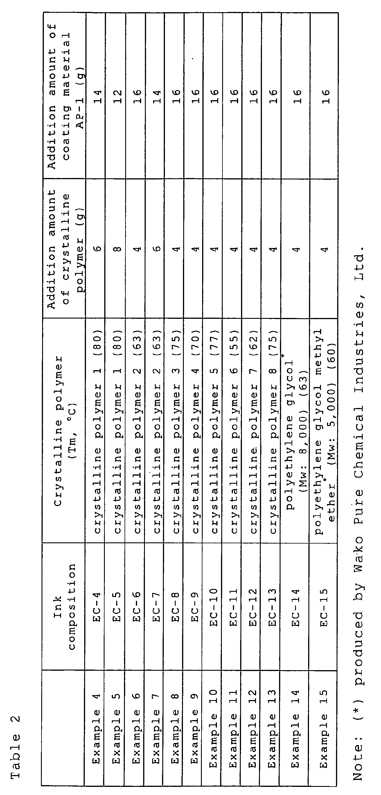

- The resulting ink compositions EC-4 to EC-22 were evaluated in the same manner as in Example 1. It was understood, as a result, that the addition of the crystalline polymer having a melting point (Tm) lowered the fixable temperature and simultaneously satisfied the antiblocking property.
- According to the invention, such an ink composition and an inkjet recording method are provided that are capable of fixing an image with high quality to a recording medium at a low temperature with high speed.
- In particular, the polymer having a melting point (Tm) is melted sharply with respect to temperature (sharp melt property) to attain sharp melt property with anti-blocking property maintained, whereby an image can be fixed at a low temperature with high speed to provide an image with high quality.
- The entire disclosure of each and every foreign patent application from which the benefit of foreign priority has been claimed in the present application is incorporated herein by reference, as if fully set forth.
Claims (9)
- An ink composition for electrostatic inkjet recording, comprising:wherein the charged particle contains at least one polymer, and said at least one polymer includes at least one first polymer having a melting point.a dispersion medium; anda charged particle comprising a colorant,
- The ink composition for electrostatic inkjet recording of claim 1,
wherein the melting point of said at least one first polymer is from 40 to 100°C. - The ink composition for electrostatic inkjet recording of claim 1,
wherein said at least one polymer includes said at least one first polymer in amount of from 5 to 100% by weight. - The ink composition for electrostatic inkjet recording of claim 1,
wherein said at least one first polymer comprises a crystalline polyester compound. - The ink composition for electrostatic inkjet recording of claim 1,
wherein said at least one first polymer comprises a crystalline polyethylene compound. - The ink composition for electrostatic inkjet recording of claim 1,
wherein said at least one first polymer comprises a crystalline polyethylene glycol compound. - The ink composition for electrostatic inkjet recording of claim 1,
wherein the charged particle further contains a coating material that coats the colorant, the coating material comprising at least one of (i) said at least one first polymer and (ii) at least one second polymer not having a melting point. - The ink composition for electrostatic inkjet recording of claim 7,
which has the coating material in amount of 0.1 to 40% by weight. - An method of inkjet recording comprising:wherein the ink composition comprises:flying an ink droplet of an ink composition by utilizing an electrostatic field,wherein the charged particle contains at least one polymer, and said at least one polymer includes at least one first polymer having a melting point.a dispersion medium; anda charged particle comprising a colorant,
Applications Claiming Priority (2)
| Application Number | Priority Date | Filing Date | Title |
|---|---|---|---|
| JP2003300013 | 2003-08-25 | ||
| JP2003300013A JP2005068293A (en) | 2003-08-25 | 2003-08-25 | Ink composition and inkjet recording method |
Publications (2)
| Publication Number | Publication Date |
|---|---|
| EP1510559A1 true EP1510559A1 (en) | 2005-03-02 |
| EP1510559B1 EP1510559B1 (en) | 2006-11-29 |
Family
ID=34101154
Family Applications (1)
| Application Number | Title | Priority Date | Filing Date |
|---|---|---|---|
| EP20040020199 Expired - Lifetime EP1510559B1 (en) | 2003-08-25 | 2004-08-25 | Ink composition and ink jet recording method |
Country Status (6)
| Country | Link |
|---|---|
| US (1) | US7201478B2 (en) |
| EP (1) | EP1510559B1 (en) |
| JP (1) | JP2005068293A (en) |
| CN (1) | CN100348677C (en) |
| AT (1) | ATE346893T1 (en) |
| DE (1) | DE602004003437T2 (en) |
Cited By (1)
| Publication number | Priority date | Publication date | Assignee | Title |
|---|---|---|---|---|
| WO2011009488A1 (en) * | 2009-07-23 | 2011-01-27 | Hewlett-Packard Indigo B.V. | Electrophotographic ink, liquid toner producing methods, and digital printing methods |
Families Citing this family (4)
| Publication number | Priority date | Publication date | Assignee | Title |
|---|---|---|---|---|
| US20050131101A1 (en) * | 2003-10-03 | 2005-06-16 | Fuji Photo Film Co., Ltd. | Ink composition and inkjet recording method |
| TWI312799B (en) * | 2005-12-30 | 2009-08-01 | Ind Tech Res Inst | Viscosity controllable highly conductive ink composition and method for fabricating a metal conductive pattern |
| CN102234455B (en) * | 2010-04-21 | 2013-12-11 | 株式会社东芝 | Aqueous inkjet ink and inkjet print method |
| US10201985B2 (en) * | 2015-08-18 | 2019-02-12 | Hp Printing Korea Co., Ltd. | Dryer for inkjet image forming apparatus and image forming system having the same |
Citations (5)
| Publication number | Priority date | Publication date | Assignee | Title |
|---|---|---|---|---|
| JP2000327971A (en) * | 1999-05-24 | 2000-11-28 | Fuji Photo Film Co Ltd | Oily ink for electrostatic ink jet |
| JP2001279139A (en) * | 2000-03-30 | 2001-10-10 | Matsushita Electric Ind Co Ltd | Black ink for electrostatic ink jet recording apparatus and method for producing the same |
| EP1205815A1 (en) * | 2000-11-10 | 2002-05-15 | Samsung Electronics Co., Ltd. | Liquid inks comprising surface-treated colorant particles and manufacturing method thereof |
| US6412937B1 (en) * | 1998-10-28 | 2002-07-02 | Fuji Photo Film Co. Ltd. | Oil ink composition for electrostatic attraction ink jet and recording process using same |
| US20020195584A1 (en) * | 2000-08-18 | 2002-12-26 | Bjarne Nielsen | Composition |
Family Cites Families (7)
| Publication number | Priority date | Publication date | Assignee | Title |
|---|---|---|---|---|
| ATE224936T1 (en) * | 1993-07-01 | 2002-10-15 | Tonejet Corp Pty Ltd | LIQUID INK FOR INKJET PRINTING |
| DE19521960B4 (en) * | 1994-06-17 | 2008-03-13 | Ricoh Co., Ltd. | Recording method using an ink composition |
| JP3531766B2 (en) | 1994-06-17 | 2004-05-31 | 株式会社リコー | Ink composition and novel recording method |
| JP3315334B2 (en) | 1997-02-19 | 2002-08-19 | 株式会社東芝 | Ink jet recording device |
| US6158844A (en) * | 1996-09-13 | 2000-12-12 | Kabushiki Kaisha Toshiba | Ink-jet recording system using electrostatic force to expel ink |
| JP4196559B2 (en) * | 2001-12-07 | 2008-12-17 | コニカミノルタホールディングス株式会社 | Colored fine particles, inkjet recording ink containing the colored fine particles, method for producing the ink, and inkjet recording method |
| JP2004217835A (en) * | 2003-01-16 | 2004-08-05 | Ricoh Co Ltd | Liquid toner jet ink and recording method using the same |
-
2003
- 2003-08-25 JP JP2003300013A patent/JP2005068293A/en active Pending
-
2004
- 2004-08-24 CN CNB2004100644132A patent/CN100348677C/en not_active Expired - Fee Related
- 2004-08-25 EP EP20040020199 patent/EP1510559B1/en not_active Expired - Lifetime
- 2004-08-25 AT AT04020199T patent/ATE346893T1/en not_active IP Right Cessation
- 2004-08-25 DE DE200460003437 patent/DE602004003437T2/en not_active Expired - Lifetime
- 2004-08-25 US US10/925,029 patent/US7201478B2/en not_active Expired - Fee Related
Patent Citations (5)
| Publication number | Priority date | Publication date | Assignee | Title |
|---|---|---|---|---|
| US6412937B1 (en) * | 1998-10-28 | 2002-07-02 | Fuji Photo Film Co. Ltd. | Oil ink composition for electrostatic attraction ink jet and recording process using same |
| JP2000327971A (en) * | 1999-05-24 | 2000-11-28 | Fuji Photo Film Co Ltd | Oily ink for electrostatic ink jet |
| JP2001279139A (en) * | 2000-03-30 | 2001-10-10 | Matsushita Electric Ind Co Ltd | Black ink for electrostatic ink jet recording apparatus and method for producing the same |
| US20020195584A1 (en) * | 2000-08-18 | 2002-12-26 | Bjarne Nielsen | Composition |
| EP1205815A1 (en) * | 2000-11-10 | 2002-05-15 | Samsung Electronics Co., Ltd. | Liquid inks comprising surface-treated colorant particles and manufacturing method thereof |
Non-Patent Citations (2)
| Title |
|---|
| PATENT ABSTRACTS OF JAPAN vol. 2000, no. 14 5 March 2001 (2001-03-05) * |
| PATENT ABSTRACTS OF JAPAN vol. 2002, no. 02 2 April 2002 (2002-04-02) * |
Cited By (2)
| Publication number | Priority date | Publication date | Assignee | Title |
|---|---|---|---|---|
| WO2011009488A1 (en) * | 2009-07-23 | 2011-01-27 | Hewlett-Packard Indigo B.V. | Electrophotographic ink, liquid toner producing methods, and digital printing methods |
| US8617783B2 (en) | 2009-07-23 | 2013-12-31 | Hewlett-Packard Indigo B.V. | Electrophotographic ink, liquid toner producing methods, and digital printing methods |
Also Published As
| Publication number | Publication date |
|---|---|
| US7201478B2 (en) | 2007-04-10 |
| ATE346893T1 (en) | 2006-12-15 |
| JP2005068293A (en) | 2005-03-17 |
| DE602004003437T2 (en) | 2007-10-04 |
| CN1597803A (en) | 2005-03-23 |
| US20050046683A1 (en) | 2005-03-03 |
| CN100348677C (en) | 2007-11-14 |
| EP1510559B1 (en) | 2006-11-29 |
| DE602004003437D1 (en) | 2007-01-11 |
Similar Documents
| Publication | Publication Date | Title |
|---|---|---|
| EP1541644B1 (en) | Ink composition and inkjet recording method | |
| EP1471121B1 (en) | Inkjet recording ink composition and inkjet recording method | |
| US7201478B2 (en) | Ink composition and inkjet recording method | |
| US20050143491A1 (en) | Ink composition for ink jet recording, manufacturing method of the same, and ink jet recording method | |
| EP1661958A1 (en) | Process for producing ink composistion | |
| EP1547776B1 (en) | Inkjet recording method | |
| JP4388782B2 (en) | Inkjet recording method | |
| EP1520884B1 (en) | Ink composition and inkjet recording method | |
| JP2005103958A (en) | Inkjet recording method | |
| JP4625666B2 (en) | Ink composition and inkjet recording method | |
| EP1637569B1 (en) | Method of manufacturing ink composition | |
| US20050143492A1 (en) | Ink composition for inkjet recording and inkjet recording method | |
| EP1605024A1 (en) | Particles, method for manufacturing the particles and ink composition | |
| US20060116440A1 (en) | Ink composition and ink jet recording method | |
| JP2005082680A (en) | Ink composition and inkjet recording method | |
| JP4654023B2 (en) | Inkjet recording method | |
| JP2006152107A (en) | Ink composition and method for producing the same | |
| JP2006249246A (en) | Electrostatic ink-jet ink composition and ink-jet printing method | |
| JP2006316226A (en) | Ink composition for electrostatic ink jet and method for ink jet recording | |
| JP2005028843A (en) | Ink jet recording method | |
| JP2006316227A (en) | Ink composition for electrostatic ink jet and method for ink jet recording | |
| JP2006249247A (en) | Electrostatic ink-jet ink composition and ink-jet printing method | |
| JP2006239872A (en) | Imaging method | |
| JP2006199820A (en) | Ink composition for electrostatic ink jet recording, and ink jet recording method | |
| JP2006169387A (en) | Method for producing ink composition and inkjet recording method |
Legal Events
| Date | Code | Title | Description |
|---|---|---|---|
| PUAI | Public reference made under article 153(3) epc to a published international application that has entered the european phase |
Free format text: ORIGINAL CODE: 0009012 |
|
| AK | Designated contracting states |
Kind code of ref document: A1 Designated state(s): AT BE BG CH CY CZ DE DK EE ES FI FR GB GR HU IE IT LI LU MC NL PL PT RO SE SI SK TR |
|
| AX | Request for extension of the european patent |
Extension state: AL HR LT LV MK |
|
| RIN1 | Information on inventor provided before grant (corrected) |
Inventor name: KASAI, SEISHIC/O FUJI PHOTO FILM CO.LTD. |
|
| 17P | Request for examination filed |
Effective date: 20050427 |
|
| AKX | Designation fees paid |
Designated state(s): AT BE BG CH CY CZ DE DK EE ES FI FR GB GR HU IE IT LI LU MC NL PL PT RO SE SI SK TR |
|
| GRAP | Despatch of communication of intention to grant a patent |
Free format text: ORIGINAL CODE: EPIDOSNIGR1 |
|
| GRAS | Grant fee paid |
Free format text: ORIGINAL CODE: EPIDOSNIGR3 |
|
| GRAA | (expected) grant |
Free format text: ORIGINAL CODE: 0009210 |
|
| AK | Designated contracting states |
Kind code of ref document: B1 Designated state(s): AT BE BG CH CY CZ DE DK EE ES FI FR GB GR HU IE IT LI LU MC NL PL PT RO SE SI SK TR |
|
| PG25 | Lapsed in a contracting state [announced via postgrant information from national office to epo] |
Ref country code: IT Free format text: LAPSE BECAUSE OF FAILURE TO SUBMIT A TRANSLATION OF THE DESCRIPTION OR TO PAY THE FEE WITHIN THE PRESCRIBED TIME-LIMIT;WARNING: LAPSES OF ITALIAN PATENTS WITH EFFECTIVE DATE BEFORE 2007 MAY HAVE OCCURRED AT ANY TIME BEFORE 2007. THE CORRECT EFFECTIVE DATE MAY BE DIFFERENT FROM THE ONE RECORDED. Effective date: 20061129 Ref country code: SI Free format text: LAPSE BECAUSE OF FAILURE TO SUBMIT A TRANSLATION OF THE DESCRIPTION OR TO PAY THE FEE WITHIN THE PRESCRIBED TIME-LIMIT Effective date: 20061129 Ref country code: SK Free format text: LAPSE BECAUSE OF FAILURE TO SUBMIT A TRANSLATION OF THE DESCRIPTION OR TO PAY THE FEE WITHIN THE PRESCRIBED TIME-LIMIT Effective date: 20061129 Ref country code: LI Free format text: LAPSE BECAUSE OF FAILURE TO SUBMIT A TRANSLATION OF THE DESCRIPTION OR TO PAY THE FEE WITHIN THE PRESCRIBED TIME-LIMIT Effective date: 20061129 Ref country code: AT Free format text: LAPSE BECAUSE OF FAILURE TO SUBMIT A TRANSLATION OF THE DESCRIPTION OR TO PAY THE FEE WITHIN THE PRESCRIBED TIME-LIMIT Effective date: 20061129 Ref country code: BE Free format text: LAPSE BECAUSE OF FAILURE TO SUBMIT A TRANSLATION OF THE DESCRIPTION OR TO PAY THE FEE WITHIN THE PRESCRIBED TIME-LIMIT Effective date: 20061129 Ref country code: CZ Free format text: LAPSE BECAUSE OF FAILURE TO SUBMIT A TRANSLATION OF THE DESCRIPTION OR TO PAY THE FEE WITHIN THE PRESCRIBED TIME-LIMIT Effective date: 20061129 Ref country code: RO Free format text: LAPSE BECAUSE OF FAILURE TO SUBMIT A TRANSLATION OF THE DESCRIPTION OR TO PAY THE FEE WITHIN THE PRESCRIBED TIME-LIMIT Effective date: 20061129 Ref country code: CH Free format text: LAPSE BECAUSE OF FAILURE TO SUBMIT A TRANSLATION OF THE DESCRIPTION OR TO PAY THE FEE WITHIN THE PRESCRIBED TIME-LIMIT Effective date: 20061129 Ref country code: FI Free format text: LAPSE BECAUSE OF FAILURE TO SUBMIT A TRANSLATION OF THE DESCRIPTION OR TO PAY THE FEE WITHIN THE PRESCRIBED TIME-LIMIT Effective date: 20061129 Ref country code: PL Free format text: LAPSE BECAUSE OF FAILURE TO SUBMIT A TRANSLATION OF THE DESCRIPTION OR TO PAY THE FEE WITHIN THE PRESCRIBED TIME-LIMIT Effective date: 20061129 Ref country code: NL Free format text: LAPSE BECAUSE OF FAILURE TO SUBMIT A TRANSLATION OF THE DESCRIPTION OR TO PAY THE FEE WITHIN THE PRESCRIBED TIME-LIMIT Effective date: 20061129 |
|
| REG | Reference to a national code |
Ref country code: GB Ref legal event code: FG4D |
|
| REG | Reference to a national code |
Ref country code: CH Ref legal event code: EP |
|
| REG | Reference to a national code |
Ref country code: IE Ref legal event code: FG4D |
|
| REF | Corresponds to: |
Ref document number: 602004003437 Country of ref document: DE Date of ref document: 20070111 Kind code of ref document: P |
|
| PG25 | Lapsed in a contracting state [announced via postgrant information from national office to epo] |
Ref country code: BG Free format text: LAPSE BECAUSE OF FAILURE TO SUBMIT A TRANSLATION OF THE DESCRIPTION OR TO PAY THE FEE WITHIN THE PRESCRIBED TIME-LIMIT Effective date: 20070228 Ref country code: DK Free format text: LAPSE BECAUSE OF FAILURE TO SUBMIT A TRANSLATION OF THE DESCRIPTION OR TO PAY THE FEE WITHIN THE PRESCRIBED TIME-LIMIT Effective date: 20070228 Ref country code: SE Free format text: LAPSE BECAUSE OF FAILURE TO SUBMIT A TRANSLATION OF THE DESCRIPTION OR TO PAY THE FEE WITHIN THE PRESCRIBED TIME-LIMIT Effective date: 20070228 |
|
| PG25 | Lapsed in a contracting state [announced via postgrant information from national office to epo] |
Ref country code: ES Free format text: LAPSE BECAUSE OF FAILURE TO SUBMIT A TRANSLATION OF THE DESCRIPTION OR TO PAY THE FEE WITHIN THE PRESCRIBED TIME-LIMIT Effective date: 20070312 |
|
| RAP2 | Party data changed (patent owner data changed or rights of a patent transferred) |
Owner name: FUJIFILM CORPORATION |
|
| REG | Reference to a national code |
Ref country code: GB Ref legal event code: 732E |
|
| PG25 | Lapsed in a contracting state [announced via postgrant information from national office to epo] |
Ref country code: PT Free format text: LAPSE BECAUSE OF FAILURE TO SUBMIT A TRANSLATION OF THE DESCRIPTION OR TO PAY THE FEE WITHIN THE PRESCRIBED TIME-LIMIT Effective date: 20070430 |
|
| NLT2 | Nl: modifications (of names), taken from the european patent patent bulletin |
Owner name: FUJIFILM CORPORATION Effective date: 20070314 |
|
| NLV1 | Nl: lapsed or annulled due to failure to fulfill the requirements of art. 29p and 29m of the patents act | ||
| REG | Reference to a national code |
Ref country code: CH Ref legal event code: PL |
|
| EN | Fr: translation not filed | ||
| PLBE | No opposition filed within time limit |
Free format text: ORIGINAL CODE: 0009261 |
|
| STAA | Information on the status of an ep patent application or granted ep patent |
Free format text: STATUS: NO OPPOSITION FILED WITHIN TIME LIMIT |
|
| 26N | No opposition filed |
Effective date: 20070830 |
|
| PG25 | Lapsed in a contracting state [announced via postgrant information from national office to epo] |
Ref country code: FR Free format text: LAPSE BECAUSE OF FAILURE TO SUBMIT A TRANSLATION OF THE DESCRIPTION OR TO PAY THE FEE WITHIN THE PRESCRIBED TIME-LIMIT Effective date: 20070720 Ref country code: MC Free format text: LAPSE BECAUSE OF NON-PAYMENT OF DUE FEES Effective date: 20070831 Ref country code: GR Free format text: LAPSE BECAUSE OF FAILURE TO SUBMIT A TRANSLATION OF THE DESCRIPTION OR TO PAY THE FEE WITHIN THE PRESCRIBED TIME-LIMIT Effective date: 20070301 |
|
| PG25 | Lapsed in a contracting state [announced via postgrant information from national office to epo] |
Ref country code: IE Free format text: LAPSE BECAUSE OF NON-PAYMENT OF DUE FEES Effective date: 20070827 |
|
| PG25 | Lapsed in a contracting state [announced via postgrant information from national office to epo] |
Ref country code: FR Free format text: LAPSE BECAUSE OF FAILURE TO SUBMIT A TRANSLATION OF THE DESCRIPTION OR TO PAY THE FEE WITHIN THE PRESCRIBED TIME-LIMIT Effective date: 20061129 |
|
| PG25 | Lapsed in a contracting state [announced via postgrant information from national office to epo] |
Ref country code: EE Free format text: LAPSE BECAUSE OF FAILURE TO SUBMIT A TRANSLATION OF THE DESCRIPTION OR TO PAY THE FEE WITHIN THE PRESCRIBED TIME-LIMIT Effective date: 20061129 |
|
| PG25 | Lapsed in a contracting state [announced via postgrant information from national office to epo] |
Ref country code: CY Free format text: LAPSE BECAUSE OF FAILURE TO SUBMIT A TRANSLATION OF THE DESCRIPTION OR TO PAY THE FEE WITHIN THE PRESCRIBED TIME-LIMIT Effective date: 20061129 Ref country code: LU Free format text: LAPSE BECAUSE OF NON-PAYMENT OF DUE FEES Effective date: 20070825 |
|
| PG25 | Lapsed in a contracting state [announced via postgrant information from national office to epo] |
Ref country code: TR Free format text: LAPSE BECAUSE OF FAILURE TO SUBMIT A TRANSLATION OF THE DESCRIPTION OR TO PAY THE FEE WITHIN THE PRESCRIBED TIME-LIMIT Effective date: 20061129 Ref country code: HU Free format text: LAPSE BECAUSE OF FAILURE TO SUBMIT A TRANSLATION OF THE DESCRIPTION OR TO PAY THE FEE WITHIN THE PRESCRIBED TIME-LIMIT Effective date: 20070530 |
|
| PGFP | Annual fee paid to national office [announced via postgrant information from national office to epo] |
Ref country code: DE Payment date: 20110727 Year of fee payment: 8 Ref country code: GB Payment date: 20110824 Year of fee payment: 8 |
|
| GBPC | Gb: european patent ceased through non-payment of renewal fee |
Effective date: 20120825 |
|
| PG25 | Lapsed in a contracting state [announced via postgrant information from national office to epo] |
Ref country code: DE Free format text: LAPSE BECAUSE OF NON-PAYMENT OF DUE FEES Effective date: 20130301 Ref country code: GB Free format text: LAPSE BECAUSE OF NON-PAYMENT OF DUE FEES Effective date: 20120825 |
|
| REG | Reference to a national code |
Ref country code: DE Ref legal event code: R119 Ref document number: 602004003437 Country of ref document: DE Effective date: 20130301 |