EP1510374A2 - Method for estimating the transverse acceleration of a vehicle - Google Patents
Method for estimating the transverse acceleration of a vehicle Download PDFInfo
- Publication number
- EP1510374A2 EP1510374A2 EP04014280A EP04014280A EP1510374A2 EP 1510374 A2 EP1510374 A2 EP 1510374A2 EP 04014280 A EP04014280 A EP 04014280A EP 04014280 A EP04014280 A EP 04014280A EP 1510374 A2 EP1510374 A2 EP 1510374A2
- Authority
- EP
- European Patent Office
- Prior art keywords
- vehicle
- lateral acceleration
- expected
- steering angle
- esc
- Prior art date
- Legal status (The legal status is an assumption and is not a legal conclusion. Google has not performed a legal analysis and makes no representation as to the accuracy of the status listed.)
- Withdrawn
Links
Images

Classifications
-
- B—PERFORMING OPERATIONS; TRANSPORTING
- B60—VEHICLES IN GENERAL
- B60G—VEHICLE SUSPENSION ARRANGEMENTS
- B60G17/00—Resilient suspensions having means for adjusting the spring or vibration-damper characteristics, for regulating the distance between a supporting surface and a sprung part of vehicle or for locking suspension during use to meet varying vehicular or surface conditions, e.g. due to speed or load
- B60G17/015—Resilient suspensions having means for adjusting the spring or vibration-damper characteristics, for regulating the distance between a supporting surface and a sprung part of vehicle or for locking suspension during use to meet varying vehicular or surface conditions, e.g. due to speed or load the regulating means comprising electric or electronic elements
- B60G17/016—Resilient suspensions having means for adjusting the spring or vibration-damper characteristics, for regulating the distance between a supporting surface and a sprung part of vehicle or for locking suspension during use to meet varying vehicular or surface conditions, e.g. due to speed or load the regulating means comprising electric or electronic elements characterised by their responsiveness, when the vehicle is travelling, to specific motion, a specific condition, or driver input
- B60G17/0162—Resilient suspensions having means for adjusting the spring or vibration-damper characteristics, for regulating the distance between a supporting surface and a sprung part of vehicle or for locking suspension during use to meet varying vehicular or surface conditions, e.g. due to speed or load the regulating means comprising electric or electronic elements characterised by their responsiveness, when the vehicle is travelling, to specific motion, a specific condition, or driver input mainly during a motion involving steering operation, e.g. cornering, overtaking
-
- B—PERFORMING OPERATIONS; TRANSPORTING
- B60—VEHICLES IN GENERAL
- B60T—VEHICLE BRAKE CONTROL SYSTEMS OR PARTS THEREOF; BRAKE CONTROL SYSTEMS OR PARTS THEREOF, IN GENERAL; ARRANGEMENT OF BRAKING ELEMENTS ON VEHICLES IN GENERAL; PORTABLE DEVICES FOR PREVENTING UNWANTED MOVEMENT OF VEHICLES; VEHICLE MODIFICATIONS TO FACILITATE COOLING OF BRAKES
- B60T8/00—Arrangements for adjusting wheel-braking force to meet varying vehicular or ground-surface conditions, e.g. limiting or varying distribution of braking force
- B60T8/17—Using electrical or electronic regulation means to control braking
- B60T8/172—Determining control parameters used in the regulation, e.g. by calculations involving measured or detected parameters
-
- B—PERFORMING OPERATIONS; TRANSPORTING
- B60—VEHICLES IN GENERAL
- B60T—VEHICLE BRAKE CONTROL SYSTEMS OR PARTS THEREOF; BRAKE CONTROL SYSTEMS OR PARTS THEREOF, IN GENERAL; ARRANGEMENT OF BRAKING ELEMENTS ON VEHICLES IN GENERAL; PORTABLE DEVICES FOR PREVENTING UNWANTED MOVEMENT OF VEHICLES; VEHICLE MODIFICATIONS TO FACILITATE COOLING OF BRAKES
- B60T8/00—Arrangements for adjusting wheel-braking force to meet varying vehicular or ground-surface conditions, e.g. limiting or varying distribution of braking force
- B60T8/17—Using electrical or electronic regulation means to control braking
- B60T8/1755—Brake regulation specially adapted to control the stability of the vehicle, e.g. taking into account yaw rate or transverse acceleration in a curve
- B60T8/17554—Brake regulation specially adapted to control the stability of the vehicle, e.g. taking into account yaw rate or transverse acceleration in a curve specially adapted for enhancing stability around the vehicles longitudinal axle, i.e. roll-over prevention
-
- B—PERFORMING OPERATIONS; TRANSPORTING
- B60—VEHICLES IN GENERAL
- B60G—VEHICLE SUSPENSION ARRANGEMENTS
- B60G2300/00—Indexing codes relating to the type of vehicle
- B60G2300/04—Trailers
- B60G2300/042—Semi-trailers
-
- B—PERFORMING OPERATIONS; TRANSPORTING
- B60—VEHICLES IN GENERAL
- B60G—VEHICLE SUSPENSION ARRANGEMENTS
- B60G2400/00—Indexing codes relating to detected, measured or calculated conditions or factors
- B60G2400/10—Acceleration; Deceleration
- B60G2400/104—Acceleration; Deceleration lateral or transversal with regard to vehicle
-
- B—PERFORMING OPERATIONS; TRANSPORTING
- B60—VEHICLES IN GENERAL
- B60G—VEHICLE SUSPENSION ARRANGEMENTS
- B60G2800/00—Indexing codes relating to the type of movement or to the condition of the vehicle and to the end result to be achieved by the control action
- B60G2800/70—Estimating or calculating vehicle parameters or state variables
- B60G2800/702—Improving accuracy of a sensor signal
-
- B—PERFORMING OPERATIONS; TRANSPORTING
- B60—VEHICLES IN GENERAL
- B60G—VEHICLE SUSPENSION ARRANGEMENTS
- B60G2800/00—Indexing codes relating to the type of movement or to the condition of the vehicle and to the end result to be achieved by the control action
- B60G2800/90—System Controller type
- B60G2800/91—Suspension Control
- B60G2800/912—Attitude Control; levelling control
- B60G2800/9124—Roll-over protection systems, e.g. for warning or control
-
- B—PERFORMING OPERATIONS; TRANSPORTING
- B60—VEHICLES IN GENERAL
- B60T—VEHICLE BRAKE CONTROL SYSTEMS OR PARTS THEREOF; BRAKE CONTROL SYSTEMS OR PARTS THEREOF, IN GENERAL; ARRANGEMENT OF BRAKING ELEMENTS ON VEHICLES IN GENERAL; PORTABLE DEVICES FOR PREVENTING UNWANTED MOVEMENT OF VEHICLES; VEHICLE MODIFICATIONS TO FACILITATE COOLING OF BRAKES
- B60T2230/00—Monitoring, detecting special vehicle behaviour; Counteracting thereof
- B60T2230/03—Overturn, rollover
-
- B—PERFORMING OPERATIONS; TRANSPORTING
- B60—VEHICLES IN GENERAL
- B60T—VEHICLE BRAKE CONTROL SYSTEMS OR PARTS THEREOF; BRAKE CONTROL SYSTEMS OR PARTS THEREOF, IN GENERAL; ARRANGEMENT OF BRAKING ELEMENTS ON VEHICLES IN GENERAL; PORTABLE DEVICES FOR PREVENTING UNWANTED MOVEMENT OF VEHICLES; VEHICLE MODIFICATIONS TO FACILITATE COOLING OF BRAKES
- B60T2230/00—Monitoring, detecting special vehicle behaviour; Counteracting thereof
- B60T2230/06—Tractor-trailer swaying
Definitions
- the invention relates to a method for Estimation of a lateral acceleration of a vehicle according to the preamble of claim 1.
- EBS electronic brake systems
- the last mentioned overturn prevention which in the Stability control can be integrated, has the Task, the vehicle in difficult driving situations to prevent it from falling over. Such situations can, for example, the fast passage through a Curve or a quick lane change in one Be overtaking maneuver.
- tip-over prevention is the driver early by means of a signaling device warned and the vehicle in addition, if necessary Actuation of all or individual wheel brakes slows down and thus stabilizes.
- the measured used for the known method Transverse acceleration is checked by a at the same time calculated lateral acceleration, which results from the Values of the speed detector and the Steering angle detector is recovered. Only after one successful verification is based on a table determined whether a transition to the danger area is done. If this has been detected, a Driver warning or braking intervention.
- the invention is based on the object, a Method for obtaining a lateral acceleration quantity of a vehicle, in particular a commercial vehicle, which as early as possible critical Transverse acceleration value of the vehicle detects.
- the RSC function Rollover Stability Control
- the RSC function is thus more time available, the Reduce vehicle speed.
- the values of the steering angle and the Vehicle speed is to be expected Determine the lateral acceleration of the vehicle, which of the actual, with one installed in the vehicle Transverse acceleration sensor measured lateral acceleration is ahead.
- the Lateral acceleration sensor as in commercial vehicles, especially saddles usual, relatively far back, namely in the area of the charge center of gravity, is arranged.
- the Transverse acceleration sensor in the method of DE 199 58 221 A1 arranged directly in front of the rear axle.
- Fig. 1 shows a schematic representation of a Tractor in top view, which is currently in one Left turn is located. It is with (1) the train carriage and denoted by (2) the semi-trailer.
- the focus of the Pulling cart (1) moves at a speed vz in the direction of the arrow 3.
- the focus of the Trailer (2) moves at a speed va in the direction of the arrow 4.
- the mentioned arrows 3, 4 each go from the center of gravity of the towing vehicle or trailer, and are not with identical to the longitudinal axes of the two vehicle parts. It follows that the drawn vehicle is straight in a cornering.
- the float angle of the towing vehicle (1) d. H. the Deviation of its actual direction of movement from its longitudinal axis is - ⁇ z.
- the corresponding Swing angle of the trailer is - ⁇ a. there the minus sign means that the vehicle is in a left turn is located.
- the steering angle of the tractor is indicated by ⁇ . This is the angle to which the front wheels of the towing vehicle deviate from the straight-ahead exhibition.
- the bending angle between the towing vehicle and semi-trailer is .phi.k.
- a first Transverse acceleration sensor (5) for measuring the Transverse acceleration aqSzm for the train carriage and one second lateral acceleration sensor (6) for measuring the Transverse acceleration aqGermanl intended for the semi-trailer. Both lateral acceleration sensors are located approximately at Location of the center of gravity of the respective vehicle parts.
- FIG. 1 Vehicle movement quantities are completely or partially in a built-in train car electronic Stability control (ESC) used (not ) Shown.
- ESC electronic Stability control
- Transverse acceleration sensor (5) uses a Commonly used ESC still sensors for the Speeds of the wheels as well as measured values of a Steering angle sensor and a yaw rate sensor for the Coaches.
- the sensors mentioned are not in the Fig. 1 shown, but known in the art.
- the acceleration values of the two Vehicle parts are calculated so that separate Sensors for vehicle longitudinal acceleration are not needed.
- the mentioned movement quantities are within the ESC by software for the description of an internal Vehicle model used.
- the ESC is always in which driving condition a e.g. flinging vehicle is currently located. Over a appropriate logic of the ESC can then through Einzelradbremsung be tried in a known manner, to stabilize the vehicle again.
- an anticipated lateral acceleration aq_expected of the vehicle is predetermined from parts of the above-mentioned movement variables.
- the steering angle of the tractor is with a usual steering angle sensor measured.
- the center of gravity speed of the tractor is calculated from the wheel speeds, where In addition, the steering angle is taken into account.
- the self-steering behavior of the vehicle is learned by the electronics of the ESC.
- ⁇ yaw rate, measured with the yaw rate sensor of the ESC
- ⁇ steering angle
- EG self-steering behavior
- the wheelbase of the tractor is well known and will parameterized in the ESC electronics.
- the inventive prediction of the lateral acceleration only applies exactly if the coefficient of friction of the Road also allows for this lateral acceleration. Therefore, the course of passing through the sensor is expedient (5) measured actual lateral acceleration of the Tractor rated during a steering movement and to correct the precalculated ones Transverse acceleration also used. If a due to the predicted lateral acceleration initiated RSC braking action due to the measured Transverse acceleration as superfluous or too strong it will be withdrawn or mitigated.
- the current states can also be advantageous of the vehicle model within the ESC regulation for Control to be used.
- Is z. Legs Instability of the vehicle i. a condition at which the vehicle understeer or oversteer, then can the calculated or expected lateral acceleration due to low coefficient of friction of the road is expected do not build up. In this case, then done in advance a software correction of the expected Lateral acceleration in the direction of lower values.
- the plausibility check described above by the Measurements of the lateral acceleration sensor and the State of the vehicle model within the ESC is running constantly in the background.
- For plausibility check are also the measured values of the steering angle sensor and a standard in a ESC yaw rate sensor used.
- the steering angle ⁇ is on again Zero declined. This means that the Vehicle is now in the left lane. Of the Driver then steers the vehicle immediately back in the right lane back. After about 5 seconds, the Steering angle ⁇ its maximum in the right direction reached. In this case, the calculated or expected lateral acceleration by about 100 milliseconds delayed relative to the steering angle. The measured, actual lateral acceleration is about another 100 Delayed in milliseconds. So it turns out Time savings of 100 milliseconds for the intervention of the RSC.
- Fig. 2 can be, as above described, with the help of the calculated or expected Transverse acceleration of the vehicle a considerable Time saving for a possible braking reaction of an ESC achieve. This will be a significant Safety gain for driver and vehicle achieved.
- This table is used in driving tests determined, and contains for all value pairs of Steering angle and vehicle speed one corresponding measured value of the expected Lateral acceleration. This value then rushes also the actual lateral acceleration before, and can as above described, advantageously in an ESC or RSC be used.
Abstract
Description
Die Erfindung bezieht sich auf ein Verfahren zur
Abschätzung einer Querbeschleunigung eines Fahrzeugs
gemäß dem Oberbegriff des Patentanspruchs 1.The invention relates to a method for
Estimation of a lateral acceleration of a vehicle
according to the preamble of
Heutige Straßenfahrzeuge, insbesondere auch Nutzfahrzeuge, werden im zunehmenden Maße mit elektonischen Bremssystemen (EBS) ausgestattet. Bei diesen erfolgt die Signalübertragung vom Bremspedal zur EBS-Elektronik über eine elektrische Verbindungsleitung. Die Beaufschlagung der Bremszylinder mittels Druckmittel erfolgt über vorgeschaltete Magnetventile. Mit diesen kann der Bremsdruck gesteigert, gehalten oder gesenkt werden. Die Magnetventile werden elektrisch von der oben genannten EBS-Elektronik angesteuert.Today's road vehicles, especially Commercial vehicles are becoming increasingly popular equipped with electronic brake systems (EBS). at This is the signal transmission from the brake pedal to EBS electronics via an electrical connection line. The application of the brake cylinder by means Pressure medium via upstream solenoid valves. With these, the brake pressure can be increased, held or lowered. The solenoid valves are electrically from the above EBS electronics driven.
Im Vergleich zu einer konventionellen, mechanischen
Bremsanlage ist es bei einem EBS möglich, unabhängig
vom Fahrer die Bremsen des Fahrzeugs mit Bremsmittel zu
beaufschlagen und somit das Fahrzeug abzubremsen. Diese
Möglichkeit wird von verschiedenen Systemen, die in das
EBS integriert sein können, genutzt. Solche Systeme
können zum Beispiel sein:
Die zuletzt erwähnte Umkipp-Verhinderung, die in die Stabilitätsregelung integriert sein kann, hat die Aufgabe, das Fahrzeug in schwierigen Fahr-Situationen vor einem Umkippen zu bewahren. Solche Situationen können beispielsweise das schnelle Durchfahren einer Kurve oder ein schneller Spurwechsel bei einem Überholmanöver sein. Durch die Umkipp-Verhinderung wird der Fahrer frühzeitig mittels einer Signaleinrichtung gewarnt und das Fahrzeug nötigenfalls zusätzlich durch Beaufschlagung aller oder einzelner Radbremsen verlangsamt und somit stabilisiert.The last mentioned overturn prevention, which in the Stability control can be integrated, has the Task, the vehicle in difficult driving situations to prevent it from falling over. Such situations can, for example, the fast passage through a Curve or a quick lane change in one Be overtaking maneuver. By the tip-over prevention is the driver early by means of a signaling device warned and the vehicle in addition, if necessary Actuation of all or individual wheel brakes slows down and thus stabilizes.
Bei einem bekannten Verfahren zur Verhinderung des Umkippens eines Fahrzeugs (DE 199 58 221 A1) wird eine kritische Querbeschleunigung bzw. Grenzbeschleunigung für das jeweilige Fahrzeug bestimmt. Während der Fahrt wird dann ständig die aktuelle Querbeschleunigung mittels eines Querbeschleunigungssensors oder aus den Werten von Radgeschwindigkeitssensoren bestimmt und mit der oben genannten Grenzbeschleunigung verglichen. Sobald etwa 75% der Grenzbeschleunigung erreicht sind, wird der Fahrer gewarnt und gegebenenfalls zusätzlich die Fahrgeschwindigkeit durch eine automatische Motordrosselung oder eine automatische Einbremsung veringert. In a known method for preventing the Tipping over of a vehicle (DE 199 58 221 A1) becomes a critical lateral acceleration or limit acceleration determined for the respective vehicle. While driving will then constantly the current lateral acceleration by means of a lateral acceleration sensor or from the Values determined by wheel speed sensors and with compared to the above limit acceleration. Once about 75% of the limit acceleration has been reached, the driver is warned and possibly in addition the driving speed through an automatic Motor throttling or automatic braking veringert.
Aus der DE 42 40 557 C2 ist weiter ein Sicherheitssystem für Fahrzeuge mit einem Lenkwinkeldetektor, einem Geschwindigkeitsdetektor und einem Querbeschleunigungsdetektor bekannt. Mit Hilfe der Meßwerte für Fahrzeuggeschwindigkeit und der Querbeschleunigung werden aus einer Tabelle ein Sicherheitsbereich und ein Gefahrenbereich definiert. Falls das Fahrzeug aus dem Sicherheitsbereich in den Gefahrenbereich gelangt, wird eine Geschwindigkeits-Reduziereinrichtung des Fahrzeugs angesteuert.From DE 42 40 557 C2 is a further Safety system for vehicles with one Steering angle detector, a speed detector and a lateral acceleration detector known. With help the measured values for vehicle speed and the Transverse acceleration will be taken from a table Security area and a danger area defined. If the vehicle leaves the security area in the Becomes danger zone, becomes a speed reducer controlled by the vehicle.
Die für das bekannte Verfahren benutzte gemessene Querbeschleunigung wird dabei überprüft durch eine gleichzeitig berechnete Querbeschleunigung, die aus den Werten des Geschwindigkeitsdetektors und des Lenkwinkeldetektors gewonnen wird. Erst nach einer erfolgreichen Überprüfung wird anhand einer Tabelle festgestellt, ob ein Übergang in den Gefahrenbereich erfolgt ist. Falls dies erkannt wurde, erfolgt eine Fahrer-Warnung oder ein Bremseingriff.The measured used for the known method Transverse acceleration is checked by a at the same time calculated lateral acceleration, which results from the Values of the speed detector and the Steering angle detector is recovered. Only after one successful verification is based on a table determined whether a transition to the danger area is done. If this has been detected, a Driver warning or braking intervention.
Für die oben erläuterten Systeme zur Umkipp-Verhinderung ist es wesentlich, so frühzeitig wie möglich einzugreifen, also das Fahrzeug zu verlangsamen. Dies ist eine Voraussetzung, ein beginnendes Umkippen des Fahrzeugs noch verhindern zu können. Das heißt mit anderen Worten, ein etwaiger kritischer Wert der Querbeschleunigung muss möglichst früh in der ESC-Elektronik vorliegen und verarbeitet werden. For the tipping prevention systems discussed above It is essential as early as possible to intervene, so the vehicle too slow it down. This is a requirement Beginning tipping the vehicle still prevent too can. In other words, a possible one critical value of the lateral acceleration must be as possible present and processed early in the ESC electronics become.
Der Erfindung liegt die Aufgabe zu Grunde, ein Verfahren zur Gewinnung einer Querbeschleunigungsgröße eines Fahrzeugs, insbesondere Nutzfahrzeugs anzugeben, welches möglichst früh einen kritischen Querbeschleunigungswert des Fahrzeugs erkennt.The invention is based on the object, a Method for obtaining a lateral acceleration quantity of a vehicle, in particular a commercial vehicle, which as early as possible critical Transverse acceleration value of the vehicle detects.
Diese Aufgabe wird durch die im Patentanspruch 1
angegebene Erfindung gelöst. Die Unteransprüche
enthalten zweckmäßige Weiterbildungen.This object is achieved by the in
Bei hoher Fahrzeuggeschwindigkeit und dynamischer Lenkbewegung durch den Fahrer kann sich sehr schnell eine kippgefährdende Querbeschleunigung aufbauen. Die RSC-Funktion (Rollover Stability Control) hat dann nur wenig Zeit, die Fahrzeuggeschwindigkeit durch Bremsung so zu verringern, daß keine Kippgefahr mehr besteht. Wird daher, wie durch die Erfindung vorgeschlagen, nicht auf die momentane tatsächliche Querbeschleunigung, sondern auf die sich wahrscheinlich einstellende Querbeschleunigung abgestellt, so bedeutet dies einen vorteilhaften zeitlichen Gewinn. Der RSC-Funktion steht somit mehr Zeit zur Verfügung, die Fahrzeuggeschwindigkeit zu verringern.At high vehicle speed and more dynamic Steering movement by the driver can be very fast build a kippgefährdende lateral acceleration. The RSC function (Rollover Stability Control) then has only little time, the vehicle speed through braking reduce so that there is no risk of tipping over. Therefore, as suggested by the invention, not on the current actual Lateral acceleration, but probably on that adjusting lateral acceleration turned off, so means this is an advantageous time gain. The RSC function is thus more time available, the Reduce vehicle speed.
Wie sich in Fahrversuchen gezeigt hat, lässt sich gemäß der Erfindung aus den Werten des Lenkwinkels und der Fahrzeuggeschwindigkeit eine zu erwartende Querbeschleunigung des Fahrzeugs bestimmen, welche der tatsächlichen, mit einem im Fahrzeug installierten Querbeschleunigungssensor gemessenen Querbeschleunigung vorauseilt. Dies gilt insbesondere dann, wenn der Querbeschleunigungssensor, wie bei Nutzfahrzeugen, insbesondere Sattelzügen üblich, relativ weit hinten, nämlich im Bereich des Ladungs-Schwerpunktes, angeordnet ist. So ist beispielsweise der Querbeschleunigungssensor bei dem Verfahren der DE 199 58 221 A1 unmittelbar vor der Hinterachse angeordnet.As has been shown in driving tests, can be according to The invention of the values of the steering angle and the Vehicle speed is to be expected Determine the lateral acceleration of the vehicle, which of the actual, with one installed in the vehicle Transverse acceleration sensor measured lateral acceleration is ahead. This is especially true when the Lateral acceleration sensor, as in commercial vehicles, especially saddles usual, relatively far back, namely in the area of the charge center of gravity, is arranged. For example, the Transverse acceleration sensor in the method of DE 199 58 221 A1 arranged directly in front of the rear axle.
Durch das erfindungsgemäße Verfahren lässt sich ein entscheidender zeitlicher Vorsprung von bis zu einigen 100 Millisekunden für die Reaktion eines Fahrzeug-Stabilitätssystems auf ein drohendes Umkippen des Fahrzeugs erzielen. Eine mit dem erfindungsgemäßen Verfahren arbeitende Stabilitätsregelung (ESC) wartet also nicht darauf, bis eine kritische Querbeschleunigung des Fahrzeugs tatsächlich vorliegt (Meßwert des Querbeschleunigungs-Sensors), sondern reagiert direkt auf die Lenkbewegungen des Fahrers und sagt hiermit (unter Verwendung weiterer Größen) eine drohende zu hohe Querbeschleunigung voraus. Durch den so vorliegenden zeitlichen Gewinn für den Bremseingriff des ESC kann in vielen Fällen das Fahrzeug noch vor dem Umkippen bewahrt werden. Die Anzahl kritischer Fahrsituationen lässt sich somit verringern.By the method according to the invention can be decisive time advantage of up to a few 100 milliseconds for the reaction of a vehicle stability system on a threatening overturning of the Vehicle. One with the invention Process Stability Control (ESC) waits so do not care until a critical one Transverse acceleration of the vehicle is actually present (Measured value of the lateral acceleration sensor), but responds directly to the driver's steering movements and hereby states (using other sizes) one impending too high lateral acceleration ahead. By the so available temporal profit for the braking intervention In many cases, the ESC can save the vehicle before the Tip over are preserved. The number of critical Driving situations can thus be reduced.
Die Erfindung wird im folgenden anhand einer Zeichnung
näher dargestellt. Diese zeigt in
Die Fig. 1 zeigt in schematischer Darstellung einen
Sattelzug in der Draufsicht, der sich gerade in einer
Linkskurve befindet. Dabei ist mit (1) der Zugwagen und
mit (2) der Auflieger bezeichnet. Der Schwerpunkt des
Zugwagens (1) bewegt sich mit einer Geschwindigkeit vz
in Richtung des Pfeiles 3. Der Schwerpunkt des
Aufliegers (2) bewegt sich mit einer Geschwindigkeit va
in Richtung des Pfeiles 4.Fig. 1 shows a schematic representation of a
Tractor in top view, which is currently in one
Left turn is located. It is with (1) the train carriage and
denoted by (2) the semi-trailer. The focus of the
Pulling cart (1) moves at a speed vz
in the direction of the arrow 3. The focus of the
Trailer (2) moves at a speed va
in the direction of the
Die genannten Pfeile 3, 4 gehen jeweils vom Schwerpunkt
des Zugwagens bzw. Aufliegers aus, und sind nicht mit
den Längsachsen der beiden Fahrzeugteile identisch.
Daraus folgt, daß sich das gezeichnete Fahrzeug gerade
in einer Kurvenfahrt befindet.The mentioned
Der Schwimmwinkel des Zugwagens (1), d. h. die Abweichung seiner tatsächlichen Bewegungsrichtung von seiner Längsachse, beträgt -βz. Der entsprechende Schwimmwinkel des Aufliegers beträgt -βa. Dabei bedeutet das Minuszeichen, daß sich das Fahrzeug in einer Linkskurve befindet.The float angle of the towing vehicle (1), d. H. the Deviation of its actual direction of movement from its longitudinal axis is -βz. The corresponding Swing angle of the trailer is -βa. there the minus sign means that the vehicle is in a left turn is located.
Der Lenkwinkel des Zugwagens ist mit δ bezeichnet. Dies ist der Winkel, um den die Vorderräder des Zugwagens von der Geradeausstellung abweichen.The steering angle of the tractor is indicated by δ. This is the angle to which the front wheels of the towing vehicle deviate from the straight-ahead exhibition.
Der Knickwinkel zwischen Zugwagen und Auflieger beträgt ϕk. The bending angle between the towing vehicle and semi-trailer is .phi.k.
Der gefahrene Radius im Schwerpunkt des Zugwagens (1) beträgt RSzm (Szm = Sattelzugmaschine), und entsprechend beträgt der gefahrene Radius im Schwerpunkt des Aufliegers (2) RAufl. Letzterer ist naturgemäß kleiner als der gefahrene Radius des Zugwagens.The driven radius in the center of gravity of the towing vehicle (1) is RSzm (Szm = semitrailer tractor), and accordingly, the driven radius is in Focus of the trailer (2) RAufl. The latter is naturally smaller than the driven radius of the Towing vehicle.
Zur Messung der tatsächlichen Querbeschleunigungen von Zugwagen (1) und Auflieger (2) ist ein erster Querbeschleunigungssensor (5) zur Messung der Querbeschleunigung aqSzm für den Zugwagen und ein zweiter Querbeschleunigungssensor (6) zur Messung der Querbeschleunigung aqAufl für den Auflieger vorgesehen. Beide Querbeschleunigungssensoren befinden sich etwa am Ort des Schwerpunktes der jeweiligen Fahrzeugteile.To measure the actual lateral accelerations of Pull car (1) and semi-trailer (2) is a first Transverse acceleration sensor (5) for measuring the Transverse acceleration aqSzm for the train carriage and one second lateral acceleration sensor (6) for measuring the Transverse acceleration aqAufl intended for the semi-trailer. Both lateral acceleration sensors are located approximately at Location of the center of gravity of the respective vehicle parts.
Bei realen Fahrzeugen wird meist aus Kostengründen auf den Beschleunigungssensor im Auflieger verzichtet.In real vehicles is mostly due to cost reasons omitted the acceleration sensor in the trailer.
Mit vx und vy sind die Fahrzeuggeschwindigkeiten im Schwerpunkt der Zugmaschine bezeichnet. Dabei gilt der Wert vx für die Längsrichtung und der Wert vy für die Querrichtung der Zugmaschine.With vx and vy the vehicle speeds are in Center of gravity of the tractor called. It applies the Value vx for the longitudinal direction and the value vy for the Transverse direction of the tractor.
Die oben erläuterten, in der Fig. 1 dargestellten Fahrzeug-Bewegungsgrößen werden ganz oder zum Teil in einer im Zugwagen eingebauten elektronischen Stabilitätsregelung (ESC) verwendet (nicht dargestellt). Zusätzlich zu den Meßwerten des Querbeschleunigungssensors (5) verwendet eine gebräuchliche ESC im allgemeinen noch Sensoren für die Drehzahlen der Räder sowie Meßwerte eines Lenkwinkelsensors und eines Gierratensensors für den Zugwagen. Die genannten Sensoren sind nicht in der Fig. 1 dargestellt, aber dem Fachmann bekannt.The above-explained, shown in FIG. 1 Vehicle movement quantities are completely or partially in a built-in train car electronic Stability control (ESC) used (not ) Shown. In addition to the measured values of the Transverse acceleration sensor (5) uses a Commonly used ESC still sensors for the Speeds of the wheels as well as measured values of a Steering angle sensor and a yaw rate sensor for the Coaches. The sensors mentioned are not in the Fig. 1 shown, but known in the art.
Aus den Werten der Radsensoren können in dem Fachmann bekannter Weise die Beschleunigungswerte der beiden Fahrzeugteile berechnet werden, so daß separate Sensoren für die Fahrzeug-Längsbeschleunigung nicht benötigt werden.From the values of the wheel sensors can in the expert known manner, the acceleration values of the two Vehicle parts are calculated so that separate Sensors for vehicle longitudinal acceleration are not needed.
Die genannten Bewegungsgrößen werden innerhalb der ESC softwaremäßig zur Beschreibung eines internen Fahrzeugmodells verwendet. Hierdurch ist der ESC stets bekannt, in welchem Fahrzustand sich ein z.B. schleuderndes Fahrzeug gerade befindet. Über eine entsprechende Logik der ESC kann dann durch Einzelradbremsung in bekannter Weise versucht werden, das Fahrzeug wieder zu stabilisieren.The mentioned movement quantities are within the ESC by software for the description of an internal Vehicle model used. As a result, the ESC is always in which driving condition a e.g. flinging vehicle is currently located. Over a appropriate logic of the ESC can then through Einzelradbremsung be tried in a known manner, to stabilize the vehicle again.
Gemäß der Erfindung wird aus Teilen der obengenannten
Bewegungsgrößen eine zu erwartende Querbeschleunigung
aq_erwartet des Fahrzeugs vorherbestimmt. Hierzu werden
wenigstens die Größen für Lenkwinkel und für die
Fahrzeuggeschwindigkeit benutzt. Die Vorausberechnung
kann erfindungsgemäß vorteilhaft mit Hilfe einer
Formel, nämlich
δ = Lenkwinkel des Fahrzeugs,
Vz = Schwerpunktsgeschwindigkeit der Sattelzugmaschine,
EG = Eigenlenkverhalten des Fahrzeugs,
RadstSzm = Radstand der SattelzugmaschineAccording to the invention, an anticipated lateral acceleration aq_expected of the vehicle is predetermined from parts of the above-mentioned movement variables. For this purpose, at least the sizes for steering angle and for the vehicle speed are used. According to the invention, the prediction can be advantageously carried out with the aid of a formula, namely
δ = steering angle of the vehicle,
Vz = center of gravity speed of the tractor,
EG = self-steering behavior of the vehicle,
RadstSzm = wheelbase of the tractor
Wie in Versuchsfahrten erkannt wurde, stellt sich aufgrund der Trägheit des Fahrzeugs, insbesondere des Zugwagens, die durch den eingestellten Lenkwinkel in Verbindung mit der Fahrzeuggeschwindigkeit eigentlich zu erwartende Querbeschleunigung nicht unmittelbar ein. Je dynamischer gelenkt wird, umso größer ist vielmehr die zeitliche Differenz zwischen dem Auftreten der erwarteten Querbeschleunigung und der gemessenen Querbeschleunigung.As was recognized in test drives, it turns out due to the inertia of the vehicle, in particular the Zugwagens, by the adjusted steering angle in Connection with the vehicle speed actually anticipated lateral acceleration is not immediate. The more dynamically directed, the greater the greater the difference in time between the occurrence of expected lateral acceleration and the measured Lateral acceleration.
Wie bereits erwähnt, kann die zeitliche Differenz einige hundert Millisekunden betragen. Dieser zeitliche Gewinn schafft bei vielen dynamischen Fahrmanövern die einzige Möglichkeit, das Fahrzeug vor dem Umkippen zu bewahren.As mentioned earlier, the time difference a few hundred milliseconds. This temporal Profit creates in many dynamic driving maneuvers the only way to prevent the vehicle from tipping over preserve.
Dies trifft besonders auf Sattelzüge zu, da es mit der normalerweise vorhandenen Sensorik nicht möglich ist, eine exakte Aussage über die Höhe der Schwerpunkte von Zugwagen und Auflieger zu treffen. Diese kann je nach Beladung variieren. Bei hohem Schwerpunkt kann erfahrungsgemäß der zeitliche Abstand zwischen dem Erreichen der Anregelschwelle der ESC und der zum Umkippen führenden Querbeschleunigung des Fahrzeugs sehr gering ausfallen. This is particularly true for articulated lorries, as it is with the normally available sensors are not possible an exact statement about the height of the focal points of Train cars and semitrailers to meet. This can vary depending on Load vary. At high center of gravity can According to experience, the time interval between the Reaching the threshold of the ESC and the Tipping leading lateral acceleration of the vehicle very low.
Die in der obenstehenden Formel enthaltenen Größen werden wie folgt bestimmt.The sizes contained in the above formula are determined as follows.
Der Lenkwinkel der Sattelzugmaschine wird mit einem üblichen Lenkwinkelsensor gemessen.The steering angle of the tractor is with a usual steering angle sensor measured.
Die Schwerpunktsgeschwindigkeit der Sattelzugmaschine wird aus deren Radgeschwindigkeiten errechnet, wobei zusätzlich der Lenkwinkel berücksichtigt wird.The center of gravity speed of the tractor is calculated from the wheel speeds, where In addition, the steering angle is taken into account.
Das Eigenlenkverhalten des Fahrzeugs wird von der
Elektronik der ESC eingelernt. Grundlage hierfür ist
die bekannte Formel für die Giergeschwindigkeit des
Fahrzeugs
Ψ = Giergeschwindigkeit, gemessen mit dem
Gierratensensor des ESC
δ= Lenkwinkel
EG = Eigenlenkverhalten
Vz = Fahrzeuggeschwindigkeit
RadstSzm = Radstand der SattelzugmaschineThe self-steering behavior of the vehicle is learned by the electronics of the ESC. The basis for this is the well-known formula for the yaw rate of the vehicle
Ψ = yaw rate, measured with the yaw rate sensor of the ESC
δ = steering angle
EG = self-steering behavior
Vz = vehicle speed
RadstSzm = wheelbase of the tractor
Der Radstand der Sattelzugmaschine ist bekannt und wird in die ESC-Elektronik parametriert.The wheelbase of the tractor is well known and will parameterized in the ESC electronics.
Stellt man die obige Gleichung nach EG um, erhält man das gesuchte Eigenlenkverhalten. Das Einlernen dieses für das Fahrzeug typischen Wertes erfolgt innerhalb festgelegter Randbedingungen, und zwar bei einer bestimmten Geschwindigkeit, einer bestimmten Querbeschleunigung und bei stabiler Fahrt.If one converts the above equation to EG, one obtains the sought-after self-steering behavior. Teaching this for the vehicle typical value takes place within fixed boundary conditions, namely at one certain speed, a specific one Lateral acceleration and stable travel.
Die erfindungsgemäße Vorhersage der Querbeschleunigung trifft nur dann genau zu, wenn der Reibwert der befahrenen Straße diese Querbeschleunigung auch zuläßt. Daher wird zweckmäßig der Verlauf der durch den Sensor (5) gemessenen tatsächlichen Querbeschleunigung der Sattelzugmaschine während einer Lenkbewegung bewertet und zur Korrektur der vorausberechneten Querbeschleunigung mitverwendet. Falls sich eine aufgrund der vorausberechneten Querbeschleunigung eingeleitete RSC-Bremsaktion aufgrund der gemessenen Querbeschleunigung als überflüssig oder zu stark herausstellt, wird diese zurückgenommen oder abgemindert.The inventive prediction of the lateral acceleration only applies exactly if the coefficient of friction of the Road also allows for this lateral acceleration. Therefore, the course of passing through the sensor is expedient (5) measured actual lateral acceleration of the Tractor rated during a steering movement and to correct the precalculated ones Transverse acceleration also used. If a due to the predicted lateral acceleration initiated RSC braking action due to the measured Transverse acceleration as superfluous or too strong it will be withdrawn or mitigated.
Weiter können vorteilhaft auch die aktuellen Zustände des Fahrzeugmodells innerhalb der ESC-Regelung zur Kontrolle mit herangezogen werden. Liegt z. B. eine Instabilität des Fahrzeugs vor, d.h. ein Zustand, bei dem das Fahrzeug unter- oder übersteuert, dann kann sich die errechnete bzw. erwartete Querbeschleunigung wegen zu geringem Reibwert der Straße voraussichtlich nicht aufbauen. In diesem Fall erfolgt dann im Voraus eine softwaremäßige Korrektur der erwarteten Querbeschleunigung in Richtung geringerer Werte.Furthermore, the current states can also be advantageous of the vehicle model within the ESC regulation for Control to be used. Is z. Legs Instability of the vehicle, i. a condition at which the vehicle understeer or oversteer, then can the calculated or expected lateral acceleration due to low coefficient of friction of the road is expected do not build up. In this case, then done in advance a software correction of the expected Lateral acceleration in the direction of lower values.
Die oben beschriebene Plausibilitätsprüfung durch die Meßwerte des Querbeschleunigungssensors sowie den Zustand des Fahrzeugmodells innerhalb der ESC läuft ständig im Hintergrund ab. Zur Plausibilitätsprüfung werden auch die Meßwerte des Lenkwinkelsensors und eines in einer ESC üblichen Gierratensensors herangezogen.The plausibility check described above by the Measurements of the lateral acceleration sensor and the State of the vehicle model within the ESC is running constantly in the background. For plausibility check are also the measured values of the steering angle sensor and a standard in a ESC yaw rate sensor used.
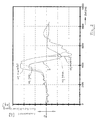
In der Fig. 2 ist der Verlauf von Lenkwinkel δ und Querschleunigung aq (gemessen sowie erwartet) bei einem Spurwechselmanöver eines Sattelzuges bei konstanter Geschwindigkeit über der Zeit aufgetragen.In Fig. 2 the course of steering angle δ and Lateral acceleration aq (measured and expected) at one Lane change maneuver of a semitrailer at constant Speed applied over time.
Zu Beginn des Fahrmanövers betragen alle Werte etwa Null, d. h. das Fahrzeug befindet sich in einer Geradeausfahrt auf der rechten Spur einer Straße. Nach etwa 2 Sekunden beginnt der Fahrer den Spurwechsel nach links, wobei die Vorderräder nach etwa 4 Sekunden maximal eingeschlagen sind (maximaler Lenkwinkel δ).At the beginning of the driving maneuver, all values are approximately Zero, d. H. the vehicle is in one Straight ahead on the right lane of a road. To about 2 seconds the driver starts the lane change left, with the front wheels after about 4 seconds maximum are taken (maximum steering angle δ).
Zu diesem Zeitpunkt hat auch die berechnete erwartete Querbeschleunigung aq erwartet ihr Maximum. Dagegen ist das Maximum der tatsächlich gemessenen Querbeschleunigung aq gem. des Fahrzeugs um etwa 200 Millisekunden verschoben, d. h. verzögert. Da sich die erwartete Querbeschleunigung auch tatsächlich eingestellt hat, liegt hier keine Instabilität des Fahrzeugs infolge glatter Straße vor.At this time also has the calculated expected Transverse acceleration aq expects its maximum. On the other hand is the maximum of the actually measured Lateral acceleration aq acc. of the vehicle by about 200 milliseconds delayed, d. H. delayed. That I the expected lateral acceleration actually has set, there is no instability of the Vehicle due to slippery road.
In die erwartete Querbeschleunigung aq_erwartet fließt das Eigenlenkverhalten EG des Fahrzeugs mit ein. Diese Größe wird von der ECU der ESC nur annähernd genau gelernt. Dadurch schlagen sich Ungenauigkeiten direkt auf die erwartete Querbeschleunigung durch. Dies ist der Grund, warum in der Fig. 2 der Wert für aq_erwartet höher ausfällt als die gemessene aq. In the expected lateral acceleration aq_expected flows the self-steering behavior EG of the vehicle with a. These Size is only approximately accurate from the ECU of the ESC learned. This will cause inaccuracies directly on the expected lateral acceleration through. This is the reason why in Fig. 2 the value for aq_expected higher than the measured aq.
Nach etwa 4,5 Sekunden ist der Lenkwinkel δ wieder auf Null zurückgegangen. Dies bedeutet, daß sich das Fahrzeug nunmehr in der linken Spur befindet. Der Fahrer lenkt das Fahrzeug anschließend sofort wieder in die rechte Spur zurück. Nach etwa 5 Sekunden hat der Lenkwinkel δ sein Maximum in die rechte Richtung erreicht. In diesem Fall ist die berechnete bzw. erwartete Querbeschleunigung um etwa 100 Millisekunden gegenüber dem Lenkwinkel verzögert. Die gemessene, tatsächliche Querbeschleunigung ist um etwa weitere 100 Millisekunden verzögert. Es ergibt sich also ein Zeitgewinn von 100 Millisekunden für das Eingreifen der RSC.After about 4.5 seconds, the steering angle δ is on again Zero declined. This means that the Vehicle is now in the left lane. Of the Driver then steers the vehicle immediately back in the right lane back. After about 5 seconds, the Steering angle δ its maximum in the right direction reached. In this case, the calculated or expected lateral acceleration by about 100 milliseconds delayed relative to the steering angle. The measured, actual lateral acceleration is about another 100 Delayed in milliseconds. So it turns out Time savings of 100 milliseconds for the intervention of the RSC.
Nach etwa 7 Sekunden befinden sich alle drei Werte wieder auf Null, d. h. das Fahrzeug fährt wiederum auf der rechten Straßenseite geradeaus.After about 7 seconds, all three values are located back to zero, d. H. the vehicle turns on again go straight on the right side of the street.
Wie aus der Fig. 2 erkennbar ist, läßt sich, wie oben beschrieben, mit Hilfe der berechneten bzw. erwarteten Querbeschleunigung des Fahrzeugs ein beträchtlicher Zeitgewinn für eine eventuelle Bremsreaktion eines ESC erzielen. Hierdurch wird ein erheblicher Sicherheitsgewinn für Fahrer und Fahrzeug erzielt.As can be seen from Fig. 2 can be, as above described, with the help of the calculated or expected Transverse acceleration of the vehicle a considerable Time saving for a possible braking reaction of an ESC achieve. This will be a significant Safety gain for driver and vehicle achieved.
Alternativ kann man vorteilhaft eine erwartete Querbeschleunigung auch mit Hilfe einer Tabelle vorausbestimmen. Diese Tabelle wird in Fahrversuchen ermittelt, und enthält für alle Wertepaare von Lenkwinkel und Fahrzeuggeschwindigkeit einen entsprechend gemessenen Wert der erwarteten Querbeschleunigung. Dieser Wert eilt dann ebenfalls der tatsächlichen Querbeschleunigung vor, und kann wie oben beschrieben, vorteilhaft in einer ESC oder RSC verwendet werden.Alternatively, one can advantageously have an expected one Lateral acceleration also with the help of a table forecast. This table is used in driving tests determined, and contains for all value pairs of Steering angle and vehicle speed one corresponding measured value of the expected Lateral acceleration. This value then rushes also the actual lateral acceleration before, and can as above described, advantageously in an ESC or RSC be used.
Claims (7)
dadurch gekennzeichnet, dass zur Bestimmung der erwarteten Querbeschleunigung zusätzlich der Radstand und/oder das Eigenlenkverhalten des Fahrzeugs berücksichtigt werden.Method according to one or both of Claims 1 and 2,
characterized in that for determining the expected lateral acceleration additionally the wheelbase and / or the self-steering behavior of the vehicle are taken into account.
EG = Eigenlenkverhalten des Fahrzeugs
Vz = Schwerpunktsgeschwindigkeit der Sattelzugmaschine
RadstSzm = Radstand der SattelzugmaschineMethod according to one or more of claims 1 to 5, characterized in that the expected lateral acceleration using the formula
EG = self-steering behavior of the vehicle
Vz = center of gravity of the tractor
RadstSzm = wheelbase of the tractor
dadurch gekennzeichnet, dass eine erwartete Querbeschleunigung des Fahrzeugs einer in Fahrversuchen ermittelten Tabelle entnommen wird, welche zu Wertepaaren von Lenkwinkel und Fahrzeuggeschwindigkeit die jeweilige zugehörige Querbeschleunigung enthält.A method for estimating a lateral acceleration of a vehicle, in particular for use in articulated vehicles within an electronic stability control (ESC) or overturning prevention (RSC) to prevent the vehicle from tipping over in critical driving situations, wherein upon reaching a critical lateral acceleration, a warning of the driver and / or a automatic speed reduction of the vehicle takes place, and wherein at least one size corresponding to the steering angle and a size corresponding to the vehicle speed are determined,
characterized in that an anticipated lateral acceleration of the vehicle is taken from a table determined in driving tests, which contains value pairs of steering angle and vehicle speed, the respective associated lateral acceleration.
Applications Claiming Priority (2)
| Application Number | Priority Date | Filing Date | Title |
|---|---|---|---|
| DE10338879 | 2003-08-23 | ||
| DE10338879A DE10338879A1 (en) | 2003-08-23 | 2003-08-23 | Method for estimating a lateral acceleration of a vehicle |
Publications (2)
| Publication Number | Publication Date |
|---|---|
| EP1510374A2 true EP1510374A2 (en) | 2005-03-02 |
| EP1510374A3 EP1510374A3 (en) | 2006-02-15 |
Family
ID=34089181
Family Applications (1)
| Application Number | Title | Priority Date | Filing Date |
|---|---|---|---|
| EP04014280A Withdrawn EP1510374A3 (en) | 2003-08-23 | 2004-06-18 | Method for estimating the transverse acceleration of a vehicle |
Country Status (4)
| Country | Link |
|---|---|
| US (1) | US20050060082A1 (en) |
| EP (1) | EP1510374A3 (en) |
| JP (1) | JP2005289347A (en) |
| DE (1) | DE10338879A1 (en) |
Cited By (4)
| Publication number | Priority date | Publication date | Assignee | Title |
|---|---|---|---|---|
| JP2010167815A (en) * | 2009-01-20 | 2010-08-05 | Hino Motors Ltd | Combination vehicle, combination pressure control method in the combination vehicle and program |
| CN102331252A (en) * | 2010-07-13 | 2012-01-25 | 曼卡车和巴士股份公司 | Method and device for recognising and compensating for a vehicle being angled across a roadway |
| WO2014012609A1 (en) * | 2012-07-19 | 2014-01-23 | Wabco Gmbh | Method for braking a combination of a plurality of vehicles coupled to one another |
| CN105636859A (en) * | 2015-10-23 | 2016-06-01 | 株式会社小松制作所 | Combination vehicle overturn-indication determination device and combination vehicle |
Families Citing this family (21)
| Publication number | Priority date | Publication date | Assignee | Title |
|---|---|---|---|---|
| US7412314B2 (en) * | 2004-09-14 | 2008-08-12 | Delphi Technologies, Inc. | Soil trip vehicle rollover detection method |
| DE102005054127A1 (en) * | 2005-11-14 | 2007-05-16 | Bosch Gmbh Robert | Method and device for controlling personal protective equipment in a rollover process |
| DE102005060820B4 (en) * | 2005-12-20 | 2022-05-19 | Zf Cv Systems Hannover Gmbh | Method for assisting in driving a vehicle |
| DE102006026692A1 (en) * | 2006-06-08 | 2007-12-13 | Edag Engineering + Design Ag | Vehicle train for controlling vehicle stability in articulated vehicles uses a pulling vehicle, a trailer and a trailer coupling linking the trailer to the pulling vehicle to move on a coupling axle |
| US7573375B2 (en) * | 2007-05-02 | 2009-08-11 | Paccar Inc | Rollover prediction and warning method |
| DE102008009522B4 (en) | 2008-02-16 | 2021-12-16 | Zf Cv Systems Hannover Gmbh | Procedure for calibrating wheel speeds |
| DE102008020410B4 (en) * | 2008-04-24 | 2016-02-11 | Ford Global Technologies, Llc (N.D.Ges.D. Staates Delaware) | Method for targeted braking of a driven wheel of a drive axle of a motor vehicle |
| DE102009013895B4 (en) * | 2009-03-19 | 2011-06-30 | Knorr-Bremse Systeme für Nutzfahrzeuge GmbH, 80809 | Vehicle with a device for controlling the driving dynamics with steering angle sensor integrated in a common unit, yaw rate sensor and acceleration sensor |
| AU2014100943B4 (en) * | 2011-03-08 | 2014-12-11 | Al-Ko International Pty Ltd | An electric stability control system and device for controlling sway stability of a caravan or trailer and the like |
| GB2489910B (en) * | 2011-03-29 | 2013-11-27 | Jaguar Cars | Control of active devices during cornering |
| CN103987603B (en) * | 2011-10-31 | 2016-11-09 | 沃尔沃拉斯特瓦格纳公司 | Method and apparatus for vehicle stabilization |
| EP2773545A4 (en) | 2011-10-31 | 2015-06-24 | Volvo Lastvagnar Ab | Method and arrangement for vehichle stabilization |
| DE102012000784A1 (en) * | 2012-01-17 | 2013-07-18 | GM Global Technology Operations LLC (n. d. Gesetzen des Staates Delaware) | Stabilization of a vehicle combination |
| EP2684753B1 (en) | 2012-07-11 | 2015-04-08 | KNORR-BREMSE Systeme für Nutzfahrzeuge GmbH | Method for estimating a vehicle's sideslip angle |
| TW201412585A (en) * | 2012-09-18 | 2014-04-01 | Automotive Res & Testing Ct | Vehicle curved road rollover prevention system and method thereof |
| DE102014000492A1 (en) * | 2014-01-14 | 2015-07-16 | Wabco Gmbh | Method for level control of a vehicle |
| JP6418373B2 (en) * | 2014-04-04 | 2018-11-07 | 日立オートモティブシステムズ株式会社 | Vehicle control apparatus and vehicle control method |
| DE102015013761A1 (en) * | 2015-10-23 | 2017-04-27 | Wabco Gmbh | Method for controlling brakes |
| US11498564B2 (en) | 2020-08-19 | 2022-11-15 | Toyota Research Institute, Inc. | Controlling a vehicle that is skidding |
| CN113830088B (en) * | 2021-10-08 | 2023-03-24 | 中南大学 | Intelligent semi-trailer tractor trajectory tracking prediction control method and vehicle |
| CN113867365A (en) * | 2021-10-28 | 2021-12-31 | 广州文远知行科技有限公司 | Method and device for determining variable acceleration of unmanned vehicle and related equipment |
Citations (2)
| Publication number | Priority date | Publication date | Assignee | Title |
|---|---|---|---|---|
| DE4240557C2 (en) | 1991-12-02 | 2001-01-04 | Koyo Seiko Co | Security system for vehicles |
| DE19958221A1 (en) | 1999-12-02 | 2001-06-07 | Wabco Gmbh & Co Ohg | Method for preventing a vehicle from tipping over |
Family Cites Families (26)
| Publication number | Priority date | Publication date | Assignee | Title |
|---|---|---|---|---|
| JP2618250B2 (en) * | 1987-12-22 | 1997-06-11 | 富士重工業株式会社 | Traction control device |
| US5216608A (en) * | 1990-01-25 | 1993-06-01 | Mitsubishi Jidosha Kogyo Kabushiki Kaisha | Apparatus and a method for estimating the friction coefficient of a road surface and controlling a driving condition of a vehicle in accordance with the estimated friction coefficient |
| DE4222958B4 (en) * | 1992-07-13 | 2004-05-27 | Robert Bosch Gmbh | Method for recognizing a vehicle situation |
| JP3039187B2 (en) * | 1993-02-25 | 2000-05-08 | トヨタ自動車株式会社 | Vehicle control device |
| JP3571370B2 (en) * | 1994-06-27 | 2004-09-29 | 富士重工業株式会社 | Vehicle driving force control device |
| US5742919A (en) * | 1996-04-26 | 1998-04-21 | Ford Global Technologies, Inc. | Method and apparatus for dynamically determining a lateral velocity of a motor vehicle |
| US5948027A (en) * | 1996-09-06 | 1999-09-07 | Ford Global Technologies, Inc. | Method for enhancing vehicle stability |
| US5825284A (en) * | 1996-12-10 | 1998-10-20 | Rollover Operations, Llc | System and method for the detection of vehicle rollover conditions |
| JP3269421B2 (en) * | 1997-04-04 | 2002-03-25 | 三菱自動車工業株式会社 | Automatic vehicle deceleration control device |
| FR2776786B1 (en) * | 1998-03-24 | 2004-07-16 | Renault | METHOD FOR MONITORING THE DYNAMIC BEHAVIOR OF A ROAD VEHICLE |
| KR100572500B1 (en) * | 1998-04-07 | 2006-04-24 | 로베르트 보쉬 게엠베하 | Method and device for stabilizing a vehicle |
| DE19827882A1 (en) * | 1998-06-23 | 1999-12-30 | Bosch Gmbh Robert | Procedure for stabilising vehicle, especially for avoiding its tipping over about longitudinal axis and/or its skidding in transverse direction |
| JP2002520604A (en) * | 1998-07-16 | 2002-07-09 | コンティネンタル・テーベス・アクチエンゲゼルシヤフト・ウント・コンパニー・オッフェネ・ハンデルスゲゼルシヤフト | Method and apparatus for detecting danger of vehicle rollover |
| DE19836674C1 (en) * | 1998-08-13 | 2000-05-25 | Daimler Chrysler Ag | Method for influencing the roll behavior of motor vehicles |
| JP4119020B2 (en) * | 1998-10-28 | 2008-07-16 | 本田技研工業株式会社 | Vehicle control device |
| DE19859966A1 (en) * | 1998-12-29 | 2000-07-13 | Bosch Gmbh Robert | Device and method for stabilizing a vehicle |
| US6304805B1 (en) * | 1999-07-21 | 2001-10-16 | Denso Corporation | Vehicle behavior estimating and controlling method and system as well as body slip angle estimating method and system |
| JP3463622B2 (en) * | 1999-09-14 | 2003-11-05 | トヨタ自動車株式会社 | Vehicle behavior control device |
| DE19958492A1 (en) * | 1999-12-04 | 2001-06-07 | Bosch Gmbh Robert | Method to determine unstable vehicle state; involves determine difference between measured transverse acceleration and transverse acceleration calculated from steering wheel angle and vehicle speed |
| US6498976B1 (en) * | 2000-10-30 | 2002-12-24 | Freightliner Llc | Vehicle operator advisor system and method |
| EP1236620B1 (en) * | 2001-03-01 | 2007-01-24 | Automotive Systems Laboratory Inc. | Vehicle rollover detection system |
| DE10122654A1 (en) * | 2001-05-10 | 2002-12-05 | Bosch Gmbh Robert | Method and system for regulating the driving behavior of a vehicle |
| DE10135020B4 (en) * | 2001-07-18 | 2005-03-03 | Robert Bosch Gmbh | Method and device for detecting and eliminating a risk of tipping over |
| DE10143355B4 (en) * | 2001-09-04 | 2019-03-21 | Continental Teves Ag & Co. Ohg | Control circuit for controlling the driving stability of a vehicle |
| DE10144880A1 (en) * | 2001-09-12 | 2003-03-27 | Bosch Gmbh Robert | Sensor circuit for determining camber of road used in motor vehicle stabilization, involves initiating automatic steering movement of vehicle and measuring yaw using sensors for storage |
| JP2003184599A (en) * | 2001-12-12 | 2003-07-03 | Aisin Seiki Co Ltd | Behavior control unit for vehicle |
-
2003
- 2003-08-23 DE DE10338879A patent/DE10338879A1/en not_active Withdrawn
-
2004
- 2004-06-18 EP EP04014280A patent/EP1510374A3/en not_active Withdrawn
- 2004-08-12 US US10/916,769 patent/US20050060082A1/en not_active Abandoned
- 2004-08-13 JP JP2004261631A patent/JP2005289347A/en active Pending
Patent Citations (2)
| Publication number | Priority date | Publication date | Assignee | Title |
|---|---|---|---|---|
| DE4240557C2 (en) | 1991-12-02 | 2001-01-04 | Koyo Seiko Co | Security system for vehicles |
| DE19958221A1 (en) | 1999-12-02 | 2001-06-07 | Wabco Gmbh & Co Ohg | Method for preventing a vehicle from tipping over |
Cited By (6)
| Publication number | Priority date | Publication date | Assignee | Title |
|---|---|---|---|---|
| JP2010167815A (en) * | 2009-01-20 | 2010-08-05 | Hino Motors Ltd | Combination vehicle, combination pressure control method in the combination vehicle and program |
| CN102331252A (en) * | 2010-07-13 | 2012-01-25 | 曼卡车和巴士股份公司 | Method and device for recognising and compensating for a vehicle being angled across a roadway |
| CN102331252B (en) * | 2010-07-13 | 2014-12-17 | 曼卡车和巴士股份公司 | Method and device for recognising and compensating for a vehicle being angled across a roadway |
| WO2014012609A1 (en) * | 2012-07-19 | 2014-01-23 | Wabco Gmbh | Method for braking a combination of a plurality of vehicles coupled to one another |
| CN105636859A (en) * | 2015-10-23 | 2016-06-01 | 株式会社小松制作所 | Combination vehicle overturn-indication determination device and combination vehicle |
| EP3354543A4 (en) * | 2015-10-23 | 2019-01-09 | Komatsu Ltd. | Combination vehicle overturn-indication determination device and combination vehicle |
Also Published As
| Publication number | Publication date |
|---|---|
| JP2005289347A (en) | 2005-10-20 |
| EP1510374A3 (en) | 2006-02-15 |
| DE10338879A1 (en) | 2005-03-17 |
| US20050060082A1 (en) | 2005-03-17 |
Similar Documents
| Publication | Publication Date | Title |
|---|---|---|
| EP1510374A2 (en) | Method for estimating the transverse acceleration of a vehicle | |
| EP1046571B1 (en) | Method for avoiding roll-over of road vehicles | |
| DE19964164B4 (en) | Apparatus and method for stabilizing a trailer from a tractor and at least one semi-trailer or trailer | |
| EP1758774B1 (en) | Process and device for stabilising a vehicle | |
| DE10144299B4 (en) | Method for driving state stabilization of a commercial vehicle association | |
| EP1107893B1 (en) | Method and device for stabilizing a vehicle | |
| EP1047585B1 (en) | Method and device for stabilising a motor vehicle in order to prevent it from rolling over | |
| EP2013069B1 (en) | Method and system for determining an optimal steering angle in understeer situations in a vehicle | |
| EP1056630B1 (en) | Device and method for stabilizing a vehicle | |
| EP0975491B1 (en) | Method and device for detecting motor vehicle tilt | |
| EP1601561B1 (en) | Method and system for controlling the driving stability of a vehicle and use of said system | |
| EP1167141B2 (en) | Stabilization of articulated trains | |
| EP1347898B1 (en) | Method and device for stabilizing a vehicle | |
| DE102007038575B4 (en) | Method for adjusting a steering angle of an electronically steered axle of a commercial vehicle | |
| WO2002036401A1 (en) | Method for regulating the driving stability of a vehicle | |
| DE10149190A1 (en) | Rolling movement control apparatus for motor vehicle, has brake force controller to control braking force of each wheel based on calculated controlling variables for attaining target rolling angle of vehicle | |
| DE19827882A1 (en) | Procedure for stabilising vehicle, especially for avoiding its tipping over about longitudinal axis and/or its skidding in transverse direction | |
| EP0989049B1 (en) | Tractor-trailer combination and method for its stabilisation | |
| DE102008013988B4 (en) | Method and device for performing an evasive maneuver | |
| DE4127750C1 (en) | Automotive equipment improving stability of car and trailer linkage - uses sensors or measurement value pick=ups to register undesired swing of trailer and automatic auxiliary linkage to counteract it | |
| EP1131235B1 (en) | Method and device for stabilising a vehicle equipped with a slip-controlled brake system | |
| DE10357254B4 (en) | Method for compensating for the yawing moment caused by a change in the rolling behavior of an impeller of a vehicle | |
| DE102004042188B4 (en) | The vehicle motion control device | |
| DE102004048531A1 (en) | Device and method for stabilizing a vehicle | |
| DE10119907B4 (en) | Method for regulating the driving stability |
Legal Events
| Date | Code | Title | Description |
|---|---|---|---|
| PUAI | Public reference made under article 153(3) epc to a published international application that has entered the european phase |
Free format text: ORIGINAL CODE: 0009012 |
|
| AK | Designated contracting states |
Kind code of ref document: A2 Designated state(s): AT BE BG CH CY CZ DE DK EE ES FI FR GB GR HU IE IT LI LU MC NL PL PT RO SE SI SK TR |
|
| AX | Request for extension of the european patent |
Extension state: AL HR LT LV MK |
|
| PUAL | Search report despatched |
Free format text: ORIGINAL CODE: 0009013 |
|
| AK | Designated contracting states |
Kind code of ref document: A3 Designated state(s): AT BE BG CH CY CZ DE DK EE ES FI FR GB GR HU IE IT LI LU MC NL PL PT RO SE SI SK TR |
|
| AX | Request for extension of the european patent |
Extension state: AL HR LT LV MK |
|
| RIC1 | Information provided on ipc code assigned before grant |
Ipc: B60T 8/00 20060101ALI20051228BHEP Ipc: B60G 17/015 20060101AFI20041122BHEP |
|
| STAA | Information on the status of an ep patent application or granted ep patent |
Free format text: STATUS: THE APPLICATION HAS BEEN WITHDRAWN |
|
| 18W | Application withdrawn |
Effective date: 20060523 |