EP1510294B1 - Power tool used for fastening a screw or a bolt - Google Patents
Power tool used for fastening a screw or a bolt Download PDFInfo
- Publication number
- EP1510294B1 EP1510294B1 EP04255128A EP04255128A EP1510294B1 EP 1510294 B1 EP1510294 B1 EP 1510294B1 EP 04255128 A EP04255128 A EP 04255128A EP 04255128 A EP04255128 A EP 04255128A EP 1510294 B1 EP1510294 B1 EP 1510294B1
- Authority
- EP
- European Patent Office
- Prior art keywords
- torque
- motor
- fastening
- bolt
- value
- Prior art date
- Legal status (The legal status is an assumption and is not a legal conclusion. Google has not performed a legal analysis and makes no representation as to the accuracy of the status listed.)
- Active
Links
- 238000006073 displacement reaction Methods 0.000 claims description 8
- 230000010354 integration Effects 0.000 claims description 2
- 230000004048 modification Effects 0.000 description 20
- 238000012986 modification Methods 0.000 description 20
- 239000000463 material Substances 0.000 description 14
- 238000000034 method Methods 0.000 description 8
- 230000008569 process Effects 0.000 description 7
- 230000007257 malfunction Effects 0.000 description 6
- 239000003638 chemical reducing agent Substances 0.000 description 4
- 238000010586 diagram Methods 0.000 description 4
- 230000007246 mechanism Effects 0.000 description 4
- 230000009467 reduction Effects 0.000 description 4
- 238000007493 shaping process Methods 0.000 description 3
- 230000000694 effects Effects 0.000 description 2
- 238000005259 measurement Methods 0.000 description 2
- 230000001133 acceleration Effects 0.000 description 1
- 230000005540 biological transmission Effects 0.000 description 1
- 239000011248 coating agent Substances 0.000 description 1
- 238000000576 coating method Methods 0.000 description 1
- 239000000428 dust Substances 0.000 description 1
- 238000001914 filtration Methods 0.000 description 1
- 230000006870 function Effects 0.000 description 1
- 230000001788 irregular Effects 0.000 description 1
- 230000007704 transition Effects 0.000 description 1
- 230000000007 visual effect Effects 0.000 description 1
Images


Classifications
-
- B—PERFORMING OPERATIONS; TRANSPORTING
- B25—HAND TOOLS; PORTABLE POWER-DRIVEN TOOLS; MANIPULATORS
- B25B—TOOLS OR BENCH DEVICES NOT OTHERWISE PROVIDED FOR, FOR FASTENING, CONNECTING, DISENGAGING OR HOLDING
- B25B21/00—Portable power-driven screw or nut setting or loosening tools; Attachments for drilling apparatus serving the same purpose
- B25B21/02—Portable power-driven screw or nut setting or loosening tools; Attachments for drilling apparatus serving the same purpose with means for imparting impact to screwdriver blade or nut socket
-
- B—PERFORMING OPERATIONS; TRANSPORTING
- B23—MACHINE TOOLS; METAL-WORKING NOT OTHERWISE PROVIDED FOR
- B23P—METAL-WORKING NOT OTHERWISE PROVIDED FOR; COMBINED OPERATIONS; UNIVERSAL MACHINE TOOLS
- B23P19/00—Machines for simply fitting together or separating metal parts or objects, or metal and non-metal parts, whether or not involving some deformation; Tools or devices therefor so far as not provided for in other classes
- B23P19/04—Machines for simply fitting together or separating metal parts or objects, or metal and non-metal parts, whether or not involving some deformation; Tools or devices therefor so far as not provided for in other classes for assembling or disassembling parts
- B23P19/06—Screw or nut setting or loosening machines
- B23P19/065—Arrangements for torque limiters or torque indicators in screw or nut setting machines
- B23P19/066—Arrangements for torque limiters or torque indicators in screw or nut setting machines by electrical means
-
- B—PERFORMING OPERATIONS; TRANSPORTING
- B25—HAND TOOLS; PORTABLE POWER-DRIVEN TOOLS; MANIPULATORS
- B25B—TOOLS OR BENCH DEVICES NOT OTHERWISE PROVIDED FOR, FOR FASTENING, CONNECTING, DISENGAGING OR HOLDING
- B25B23/00—Details of, or accessories for, spanners, wrenches, screwdrivers
- B25B23/14—Arrangement of torque limiters or torque indicators in wrenches or screwdrivers
- B25B23/1405—Arrangement of torque limiters or torque indicators in wrenches or screwdrivers for impact wrenches or screwdrivers
-
- B—PERFORMING OPERATIONS; TRANSPORTING
- B25—HAND TOOLS; PORTABLE POWER-DRIVEN TOOLS; MANIPULATORS
- B25B—TOOLS OR BENCH DEVICES NOT OTHERWISE PROVIDED FOR, FOR FASTENING, CONNECTING, DISENGAGING OR HOLDING
- B25B23/00—Details of, or accessories for, spanners, wrenches, screwdrivers
- B25B23/14—Arrangement of torque limiters or torque indicators in wrenches or screwdrivers
- B25B23/145—Arrangement of torque limiters or torque indicators in wrenches or screwdrivers specially adapted for fluid operated wrenches or screwdrivers
-
- B—PERFORMING OPERATIONS; TRANSPORTING
- B25—HAND TOOLS; PORTABLE POWER-DRIVEN TOOLS; MANIPULATORS
- B25B—TOOLS OR BENCH DEVICES NOT OTHERWISE PROVIDED FOR, FOR FASTENING, CONNECTING, DISENGAGING OR HOLDING
- B25B23/00—Details of, or accessories for, spanners, wrenches, screwdrivers
- B25B23/14—Arrangement of torque limiters or torque indicators in wrenches or screwdrivers
- B25B23/147—Arrangement of torque limiters or torque indicators in wrenches or screwdrivers specially adapted for electrically operated wrenches or screwdrivers
Definitions
- the present invention relates to a power tool such as an impact driver or an impact wrench used for fastening a screw or a bolt.
- a power tool according to the preamble of claim 1 is known from EP 0264698.
- a power tool used for fastening a screw or a bolt utilizing driving force of a motor has a function automatically stopping driving of the motor when a torque necessary for fastening the screw or the bolt reaches to a predetermined value due to the screw or the bolt is completely fastened.
- a number of impact of a hammer is sensed and driving of a motor is automatically stopped when the number of impact reaches to a predetermined reference number.
- the first conventional power impact tool which stops the driving of the motor corresponding to the impact number and the second conventional power impact tool which stops the driving of the motor corresponding to the rotation angle respectively have a disadvantage that a large difference may occur between a desired torque and the actual torque for fastening the screw or the bolt.
- the difference causes loosening of the screw or the bolt due to insufficient torque when the actual torque is much smaller than the desired torque.
- the difference causes to damage the elements to be fastened by the screw or the bolt or to damage a head of the screw or the bolt due to superfluous torque when the actual torque is much larger than the desired torque.
- the third conventional power impact tool which stops the driving of the motor corresponding to the actual torque for fastening the screw or the bolt needs a sensor provided on an output shaft for sensing the actual torque, so that it causes the cost increase and the upsizing of the power impact tool, even though the automatic stopping of the driving of the motor can be controlled precisely corresponding to the actual torque.
- a torque for fastening the bolt is estimated according to rotation speed of a shaft of a motor when an impact is applied to the bolt. It is judged that the bolt is completely fastened when the estimated torque is suddenly increased. The driving of the motor is stopped when the estimated torque is suddenly increased.
- a reference torque for judging occurrence of trouble is defined, which is a little larger than the largest torque when the torque is temporarily increased due to the trouble. While the estimated torque has not been equal to or larger than the reference torque for judging occurrence of trouble, the driving of the motor is continued, so that the occurrence of malfunction that the driving of the motor is stopped before the bolt is fastened completely can be prevented.
- a purpose of the present invention is to provide a power tool used for fastening a screw or a bolt, by which driving of a motor can surely be stopped just when the screw or the bolt is fastened completely.
- a power tool used for fastening a screw or a bolt in accordance with an aspect of the present invention comprises: a motor; a motor controller for controlling start and stop of driving of the motor; a power transmitter for transmitting driving force of the motor to a bit for fastening or loosening the screw or the bolt; a torque estimator for estimating a value of a torque for fastening the screw or the volt; and a fastening judger for judging whether the screw or the bolt is fastened completely or not.
- the fastening judger calculates a torque variation quantity ⁇ T which is a ratio of variation of the torque T with respect to a rotation angle of a shaft of the motor or elapsed time, and a torque variation ratio ⁇ ⁇ T which is a ratio of the torque variation quantity ⁇ T with respect to the rotation angle of the shaft of the motor or elapsed time. Subsequently, the fastening judger further calculates a reference index with using the torque variation ratio ⁇ ⁇ T, which is used for judging whether an increase of the value of the torque T is a temporary increase caused by a trouble in fastening operation or not.
- the fastening judger judges that the fastening operation is completed at least when the torque variation ratio ⁇ ⁇ T becomes substantially zero and the reference index becomes equal to or larger than a threshold value of trouble judgment, and outputs a signal for stopping the driving of the motor to the motor controller.
- the fastening judger can judge that the fastening operation is completed when the torque variation ratio ⁇ ⁇ T becomes substantially zero after the reference index has become equal to or larger than the threshold value of trouble judgment.
- the fastening judger can judge that the fastening operation is completed when the reference index becomes equal to or larger than the threshold value of trouble judgment after the torque variation ratio has become substantially zero.
- the driving of the motor is stopped a little before the torque for fastening the screw or the bolt becomes maximum value, so that it is especially suitable for fastening the screw or the bolt made of softer material or the smaller screw or the smaller bolt without damaging a head of the screw or the bolt.
- the fastening judger can judge that the fastening operation is completed when the value of the torque variation quantity ⁇ ⁇ T becomes substantially zero after the value of the reference index has become equal to or larger than the threshold value of trouble judgment first and the torque variation ratio has become substantially zero.
- the fastening judger can judge that the fastening operation is completed when the value of the torque variation quantity becomes substantially zero after the torque variation ratio has become substantially zero first and the value of the reference index has become equal to or larger than the threshold value of trouble judgment.
- the driving of the motor is stopped when the torque for fastening the screw or the bolt becomes substantially maximum value, so that it is especially suitable for fastening the screw or the bolt made of harder material or the larger screw or the larger bolt which is rarely damaged.
- FIG. 1 shows a configuration of a power impact tool used for fastening a screw or a bolt as an example of the power tool in the embodiment.
- the power impact tool comprises a motor 1 for generating a driving force, and a power transmitter 10 for transmitting the driving force of the motor 1 to a bit 7 for fastening or loosening a screw or a bolt (hereinafter abbreviated as "bolt”).
- the power transmitter 10 further comprises a reducer 2 for reducing rotation speed of a shaft of the motor 1 (hereinafter abbreviated as rotation speed of the motor 1), a driving shaft 3 connected to the reducer 2 and rotated by the driving force of the motor 1, a hammer 4 engaged with the driving shaft 3 via a spline bearing, an anvil 5 engaged with the driving shaft 3 with a clutch mechanism, and a spring 6 for applying pressing force to the hammer 4 toward the anvil 5.
- the hammer 4 can be moved in an axial direction of the driving shaft 3 via the spline bearing, and rotated with the driving shaft 3.
- the clutch mechanism is provided between the hammer 4 and the anvil 5.
- the hammer 4 is pressed to the anvil 5 by the pressing force of the spring 6 in an initial state.
- the bit 7 is detachable fitted to the anvil 5.
- the bit 7 can be rotated with the driving shaft 3, the hammer 4 and the anvil 5 by the driving force of the motor 1.
- a pair of cam faces is formed on, for example, an upper face of the anvil 5 and a lower face of the hammer 4, which serve as the cam mechanism.
- the cam face on the hammer 4 slips on the cam face on the anvil 5 owing to the rotation with the driving shaft 3 and the hammer 4 moves in a direction depart from the anvil 5 along the driving shaft 3 following to the elevation of the cam faces against the pressing force of the spring 6.
- the restriction due to the cam faces is suddenly released, so that the hammer 4 impacts the anvil 5 owing to charged pressing force of the spring 6 while it is rotated with the driving shaft 3.
- the motor 1 is driven by a motor driver 8 so as to start and stop the rotation of the shaft.
- the motor driver 8 is further connected to a motor controller 30, to which a signal corresponding to a displacement (pressing depth) of a trigger switch 9 is inputted.
- the motor controller 30 judges user's intention to start or to stop the driving of the motor 1 corresponding to the signal outputted from the trigger switch 9, and outputs a control signal for starting or stopping the driving of the motor 1 to the motor driver 8.
- the motor driver 8 is constituted as an analogous power circuit using a power transistor, and so on for supplying large electric current to the motor 8 stably.
- a rechargeable battery 32 is connected to the motor driver 8 for supplying electric power to the motor 1.
- the motor controller 30 is constituted by, for example, a CPU (Central Processing Unit), a ROM (Read Only Memory) and a RAM (Random Access Memory) for generating the control signals corresponding to a control program.
- the power impact tool further comprises an impact sensor 11 for sensing that the impact of the hammer 4 against the anvil 5 is carried out, a rotation angle sensor 12 for sensing the rotation angle of the anvil 5, a rotation angle calculator 13 for calculating a rotation angle ⁇ r of the anvil 5 per one impact of the hammer 4 with using outputs of the impact sensor 11 and the rotation angle sensor 12, and a torque estimator 14 for estimating a torque for fastening the bolt with using the rotation angle ⁇ r.
- These elements constitute a means for estimating the torque for fastening the bolt.
- the impact sensor 11 is a microphone 16 for sensing impact boom generated when the hammer 4 impacts the anvil 5 as a variation of voltage.
- the rotation angle sensor 12 is a rotary encoder 19 constituted by a disc 17 rotated with the anvil 5 and having slits and a transmission photo-interrupter 18 for sensing the rotation angle of the disc 17.
- the rotation angle of the anvil 5 is sensed as pulse signals.
- the microphone 16 and the rotary encoder 19 are respectively connected to a waveform shaping circuit 20 so as to be executed the filtering process, and the processed signals by the waveform shaping circuit 20 are inputted to the rotation angle calculator 13.
- the rotation angle calculator 13 serially calculates the rotation angles ⁇ r of the anvil 5 per one impact of the hammer 4, and the torque estimator 14 serially estimates the torque T for fastening the bolt. Since the calculation of the torque T is described in the above-mentioned publication gazette of Japanese Patent Application 2002-283248 in detail, the description of the calculation of the torque T is made simple.
- the symbol T designates the torque for fastening the bolt
- the symbol J designates the moment of inertia of the anvil 5
- the symbol ⁇ designates the rotation speed of the anvil 5 when the impact of the hammer 4 is carried out.
- the rotation speed of the motor 1 can be known according to the voltage of the rechargeable battery 32 and the duty in PWM (Pulse Width Modulation) control while the electric current is supplied to the motor 1, and an approximate value of the rotation speed ⁇ of the anvil 5 can be calculated by executing division of the rotation speed of the motor 1 by the reduction ratio K of the reducer 2.
- PWM Pulse Width Modulation
- the power impact tool further comprises a fastening judger 21 which calculates a torque variation quantity ⁇ T and a torque variation ratio ⁇ ⁇ T from the estimated torque T calculated by the torque estimator 14 and judges whether the fastening operation of the bolt is completed or not.
- the torque variation quantity ⁇ T corresponds to a ratio of the variation of the torque T for fastening the bolt with respect to the rotation angle of the shaft of the motor 1 or elapsed time.
- the torque variation ratio ⁇ ⁇ T corresponds to a ratio of the variation of the torque variation quantity ⁇ T with respect to the rotation angle of the motor 1 or elapsed time.
- the torque variation quantity ⁇ T is a difference between a mean value among four values of the estimated torque T and another mean value among sixteen values of the estimated torque T.
- the torque variation ratio ⁇ ⁇ T is a difference between a mean value among two values of the torque variation quantity ⁇ T and another mean value among eight values of the torque variation quantity ⁇ T.
- the fastening judger 21 calculates the above-mentioned torque variation quantity ⁇ T and the torque variation ratio ⁇ ⁇ T. Furthermore, the fastening judger 21 judges that the fastening operation is completed at least when a number of the impact of the hammer 4 occurred in a term in which the torque variation ratios ⁇ ⁇ T continuously take positive values becomes larger than a predetermined threshold value of trouble judgment and the torque variation ratio ⁇ ⁇ T becomes substantially zero.
- the fastening judger 21 judges that the fastening operation is completed, the fastening judger outputs a signal showing that the bolt has been fastened completely to the motor controller 30.
- the motor controller 30 outputs a control signal for stopping the driving of the motor to the motor driver 8 when it receives the signal from the fastening judger 21.
- FIG. 2 shows an example of the variations of the torque T, the torque variation quantity ⁇ T and the torque variation ratio ⁇ ⁇ T in the fastening operation of the bolt.
- a peak P3 appears on a curve designated by a symbol T showing the variation of the torque T, after the bolt has been fastened completely.
- a peak curve S3 designated by a symbol ⁇ ⁇ T showing the variation of the torque variation ratio ⁇ ⁇ T appears a little before the appearance of the peak P3. It is possible to judge that the bolt has been fastened completely when the peak curve S3 appears.
- peaks P1, P2 and so on appear on the curve T due to the above-mentioned troubles in the fastening operation of the bolt, and peak curves S1, S2 and so on further appear correspondingly.
- the appearance of the peak curves S 1, S2, and so on causes malfunction that the driving of the motor 1 has been stopped before the bolt is fastened completely.
- the peak values of the peak curves S 1 and S2 due to the troubles are lower than that of the peak curve S3 due to the bolt is fastened completely, so that the number of the impact of the hammer 4 (N11-N10 and N21-N20) occurred due to the trouble in a terms in which the torque variation ratios ⁇ ⁇ T continuously take positive values is smaller than the number of the impact of the hammer 4 (N31-N30) due to the bolt is fastened completely.
- the above-mentioned predetermined threshold value of trouble judgment is defined to be larger than the value of the impact of the hammer 4 due to the trouble and smaller than that due to the bolt is fastened completely.
- the fastening judger 21 uses the number of the impact of the hammer 4 in the term in which the torque variation ratios ⁇ ⁇ T continuously take positive values as a reference index for judging whether the increase of the torque T for fastening the bolt is caused by the trouble or not. Since the value according to the torque variation ratio ⁇ ⁇ T is adopted as the reference index, the cause of the increase of the torque for fastening the bolt can precisely be judged with using the peak curves S1, S2, S3 ... of the torque variation ratio ⁇ ⁇ T.
- the reference index is not limited to the number of the impact of the hammer 4. It is possible to use the time period of the term in which the torque variation ratios ⁇ ⁇ T continuously take positive values as the reference index.
- the threshold value of trouble judgment is not necessarily defined as a predetermined value. It is possible to define a value calculated from a maximum value of the torque variation ratio ⁇ ⁇ T MAX as the threshold value of trouble judgment.
- FIG. 3 shows an example of specific values of the torque variation ratio ⁇ ⁇ T and the impact number of the hammer 4 with respect to the peak curve S1.
- the threshold value of trouble judgment can be calculated as a value in proportion to the maximum vale of the torque variation ratio ⁇ ⁇ T MAX ( ⁇ ⁇ T MAX ⁇ C1 (constant value)).
- the value ⁇ ⁇ T103 corresponds to the maximum vale of the torque variation ratio ⁇ ⁇ T MAX in the case shown in FIG.
- the calculated threshold value of trouble judgment ( ⁇ ⁇ T 103 ⁇ C1) is compared with the number of impact of the hammer 4 (N11-N10) as the reference index.
- N11-N10 > ( ⁇ ⁇ T 103 ⁇ C1)
- the fastening judger 21 judges that the fastening operation of the bolt has been completed.
- (N11-N10) ⁇ ( ⁇ ⁇ T 103 ⁇ C1) the fastening judger 21 judges that the torque has been increased due to a temporary trouble.
- the threshold value of trouble judgment is defined to be larger than the sum ⁇ ( A ⁇ T) of values of the torque variation ratios ⁇ ⁇ T due to the trouble and smaller than the sum ⁇ ( ⁇ ⁇ T) of values of the torque variation ratios ⁇ ⁇ T due to the bolt is fastened completely.
- the sum ⁇ ( ⁇ ⁇ T) ⁇ ⁇ T10+ ⁇ ⁇ T101+ ⁇ ⁇ T102+•••+ ⁇ ⁇ T11.
- the reference index is not limited to the sum ⁇ ( ⁇ ⁇ T) of values of the torque variation ratios ⁇ ⁇ T occurred at each impact of the hammer 4 in the term in which the torque variation ratios ⁇ ⁇ T take positive values. It is possible to use a value of integration of the torque variation ratio ⁇ ⁇ T in the term in which the torque variation ratios ⁇ ⁇ T continuously take positive values as the reference index.
- the threshold value of trouble judgment is not necessarily defined as a predetermined value. It is possible to define a value calculated from a maximum value of the torque variation ratio ⁇ ⁇ T MAX as the threshold value of trouble judgment. For example, when the threshold value of trouble judgment can be calculated as a value in proportion to the maximum value of the torque variation ratio ⁇ ⁇ T MAX ( ⁇ ⁇ T MAX ⁇ C2(constant value)), the threshold value of trouble judgment is calculated as ⁇ ⁇ T103 ⁇ C2. The calculated threshold value of trouble judgment ( ⁇ ⁇ T103 ⁇ C2) is compared with the sum ⁇ ( ⁇ ⁇ T) as the reference index.
- the threshold value of trouble judgment as a value calculated from an initial value of the torque T in the fastening operation of the bolt.
- FIG. 4 shows differences between characteristics corresponding to the materials or the sizes of the bolts, under the assumption that the energy of impact of the hammer 4 is the same. As can be seen from FIG. 4, when the material of the bolt is harder, the torque T for fastening the bolt per one impact of the hammer 4 becomes larger. Alternatively, when the material of the bolt is softer or the size of the bolt is smaller, the torque T for fastening the bolt per one impact of the hammer 4 becomes smaller.
- the torque T for fastening the bolt becomes entirely smaller, and the torque variation quantity ⁇ T and the torque variation ratio ⁇ ⁇ T further become entirely smaller when the torque T at the initial state of the impact operation of the hammer 4.
- the threshold value of trouble judgment is defined to be a value in proportion to a mean value of the estimated values of the torque T in several times of the impact from the start of the fastening operation of the bolt.
- the value of the torque variation ratio ⁇ ⁇ T itself as the reference index, and to define the threshold value of trouble judgment as a value calculated from the value of the torque T at the initial state of the fastening operation of the bolt. It is noticed that the torque T, the torque variation quantity ⁇ T and the torque variation ratio ⁇ ⁇ T further become entirely smaller when the torque T at the initial state of the fastening operation of the bolt.
- the threshold value of trouble judgment is defined to be a value in proportion to a mean value of the estimated values of the torque T in several times of the impact from the start of the fastening operation of the bolt.
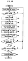
- FIG. 5 shows a basic flow of the fastening operation of the bolt in this embodiment, in which the fastening operation of the bolt is completed when the value of the reference index becomes larger than the threshold value of trouble judgment after the value of the torque variation ratio ⁇ ⁇ T becomes substantially zero.
- the motor controller 30 When the user operates the trigger switch 9, the motor controller 30 outputs a control signal for starting the driving of the motor 1 so as to fasten the bolt.
- the impact sensor 11 starts to sense the occurrence of the impact of the hammer 4 (S1).
- the rotation angle calculator 13 calculates the rotation angle ⁇ r of the anvil 5 while the hammer 4 impacts the anvil 5 (S3).
- the rotation angle calculator 13 further calculates the rotation speed ⁇ of the anvil 5 at the occurrence of the impact (S4).
- the torque estimator 14 calculates the torque T according to the above-mentioned equation (S5).
- the fastening judger 21 calculates the torque variation quantity ⁇ t and the torque variation ratio ⁇ ⁇ T (S6 and S7). Subsequently, the fastening judger 21 judges whether the value of the torque variation ratio ⁇ ⁇ T has changed from positive to negative or not (S8). When the value of the torque variation ratio ⁇ ⁇ T from positive to negative, that is, the value of the torque variation ratio ⁇ ⁇ T has become substantially zero, the fastening judger 21 further judges whether the value of the reference index becomes equal to or larger than the threshold value of trouble judgment or not (S9).
- the fastening judger 21 judges that the increase of the torque T is due to the trouble, and returns to the step S 1.
- the fastening judger 21 judges that the increase of the torque T is due to the bolt has been fastened completely, and executes the stopping process for stopping the driving of the motor 1 (S10).
- the driving of the motor 1 is stopped when the torque variation ratio ⁇ ⁇ T becomes substantially zero, which is designated by a symbol N31.
- the peak P3 of the torque T appears after the torque variation ratio ⁇ ⁇ T becomes substantially zero, which is designated by, for example, a symbol N32.
- the fastening operation of the bolt has been completed a little before the torque T for fastening the bolt takes the maximum value.
- this example is suitable for the bolt made of softer material or the smaller bolt, which can easily be damaged by superfluous torque in the fastening operation.
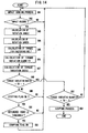
- FIG. 6 shows a modified flow of the impact sensing operation in this embodiment, in which the fastening operation of the bolt is completed when the value of the torque variation quantity ⁇ T becomes substantially zero after the torque variation ratio ⁇ ⁇ T has become substantially zero first and the value of the reference index has become equal to or larger than the threshold value of trouble judgment.
- the steps from S11 to S17 are substantially the same as the steps from S 1 to S7 in the flow shown in FIG. 5, so that the description of them are omitted.
- the fastening judger 21 judges whether a stopping flag for executing stopping process has been turned on or not (S 18). Generally, the stopping flag has not been turned on, so that the fastening judger 21 judges whether the value of the torque variation ratio ⁇ ⁇ T has changed from positive to negative or not (S 19). When the value of the torque variation ratio ⁇ ⁇ T has changed from positive to negative, the fastening judger 21 further judges whether the value of the reference index becomes equal to or larger than the threshold value of trouble judgment or not (S20).
- the fastening judger 21 judges that the increase of the torque T is due to the trouble, and returns to the step S 11.
- the fastening judger 21 judges that the increase of the torque T is due to the bolt has been fastened substantially completely, turns on the stopping flag for executing the stopping process (S21), and returns to the step S 11.
- the fastening judger 21 judges whether the value of the torque variation quantity ⁇ T has changed from positive to negative or not (S22). When the value of the torque variation quantity ⁇ T has changed from positive to negative, the fastening judger 21 judges that the increase of the torque T is due to the bolt has been fastened completely, and executes the stop operation for stopping the driving of the motor 1 (S23). Alternatively, when the value of the torque variation quantity ⁇ T has not changed from positive to negative, the fastening judger 21 judges that the bolt has not been fastened completely, and returns to the step S 11 so as to repeat the above-mentioned processes.
- the motor 1 is further driven after the torque variation ratio ⁇ ⁇ T becomes substantially zero, so that the bolt can be fastened by substantially the maximum value of the torque.
- this modification is suitable for the bolt made of harder material or the larger bolt, which is rarely damaged by the superfluous torque in the fastening operation.
- the above-mentioned two-types of the fastening control can be switched by operation of the user (operation switch is not illustrated), so that it is possible to carry out the fastening operation corresponding to the characteristics of the object to be fastened.
- the fastening judger 21 judges whether the value of the torque T is larger than a predetermined reference value or not when the torque variation ratio ⁇ ⁇ T becomes substantially zero.
- the fastening judger 21 judges that the fastening operation of a bolt made of softer material or a smaller bolt has been completed, and the motor controller 30 outputs a control signal for stopping the driving of the motor 1 to the motor driver 8.
- the fastening judger 21 further judges whether the torque variation quantity ⁇ T becomes zero, or not. When the torque variation quantity ⁇ T becomes zero, the fastening judger 21 judges that the fastening operation of a bolt made of harder material or a larger bolt has been completed, and the motor controller 30 outputs a control signal for stopping the driving of the motor 1 to the motor driver 8.
- the motor controller 30 and the motor driver 8 serve as an automatic speed controller for adjusting the rotation speed of the motor 1 corresponding to the torque T for fastening the bolt in the initial state of the fastening operation.
- the motor controller 30 compares a mean value of the estimated values of the torque T at several times of the impact of the hammer 4 from the start of the fastening operation with a predetermined reference value.
- the motor controller 30 judges that the bolt made of softer or the smaller bolt is fastened, and outputs a signal for reducing the rotation speed of the motor 1 to the motor driver 8.
- it is possible to reduce the energy of the impact by reducing the rotation speed of the motor 1 when the bolt made of the softer material or the smaller bolt, which can be damaged easily, is fastened.
- the control signal outputted from the motor controller 30 makes the rotation speed of the motor 1 slower corresponding to the degree of the value of the torque T in the initial state.
- a desired value V D of the rotation speed of the motor 1 is to be in proportion to the mean value V M of the estimated values of the torque T in several numbers of the impacts from the start of the impact operation.
- the value V D is, for example, calculated by the following equation.
- the symbol V N designates the rotation speed of the motor 1 at the present
- the symbol C3 designates a constant.
- the motor controller 30 and the motor driver 8 serving as the automatic speed controller controls the motor 1 in a manner so that the smaller the torque in the initial state of the fastening operation is, the slower the rotation speed of the motor 1 becomes.
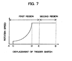
- FIG. 7 Another modification of the power impact tool in this embodiment is described with reference to FIGS. 7 and 8A to 8C.
- a stroke of the trigger switch 9 is divided into a first region and a second region so as to assure the fastening operation of the bolt.
- the output of the control signal for stooping the driving of the motor 1 is restricted, and in the second region of the stroke of the trigger switch 9, the output of the control signal for stooping the driving of the motor 1 is permitted, even when the fastening judger 21 judges that the bolt has been fastened completely.
- the trigger switch 9 is connected to a variable resistor 22 so that the displacement of the trigger switch 9 is converted to the variation of the voltage.
- a section from point A to point C in FIG. 7 is a mechanical allowance, in which the electric power is not supplied to the motor 1.
- a section from point C to point D in FIG. 7 is a speed control region, in which the rotation speed of the motor 1 is increased corresponding to increase of the displacement of the trigger switch 9.
- a section from point D to point B in FIG. 7 is a constant speed region, in which the rotation speed of the motor 1 is maintained as the maximum speed. The boundary between the first region and the second region is selected at point E in the section from the point D to the point B.
- the first region is defined as the left side from the point E, in which the displacement of the trigger switch 9 is smaller than a predetermined value at the point E.
- the second region is defined as the right side from the point E, in which the displacement of the trigger switch 9 is equal to or larger than a predetermined value at the point E.
- the user can carry out the fastening operation of the bolt with adjusting the rotation speed of the motor 1 in the first region including the speed control region until the user confirms the bolt is fastened by visual observation. Subsequently, the user can continue the fastening operation with pushing the trigger switch 9 into the second region after observing the bolt is in a state just before it is completely fastened.
- the fastening operation of the bolt can surely be completed without stopping the driving of the motor before the bolt is completely fastened, even when the fastening judger 21 has erroneously judged the bolt has been fastened completely due to the trouble.
- a click mechanism 23 is provided for applying a feel to the user when the trigger switch 9 reaches to the point E, so that the user can easily recognize the transition from the first region to the second region.
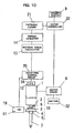
- the distance sensor 24 for sensing a distance to a face of an object 27 to be fastened by the bolt.
- the distance sensor 24 comprises a light emitting device 25 and a photo-sensing device 26.
- a light beam emitted from the light emitting device 25 is focused on the object 27 by a lens (not shown), and a reflected beam from the object 27 is received by the photo-sensing device 26, so that the distance to the object 27 from the distance sensor 24 can be sensed.
- the distance sensor 24 compares a measurement result of a distance to the object 27 with a predetermined reference distance, and outputs a sensing signal when the measurement result is shorter than the reference distance.
- the distance sensor 24 is provided at a stationary portion of the power impact tool in the vicinity of the bit 7. For example, a distance, which is a little longer than a distance from the distance sensor 24 to a surface of the object 27 when the bolt is completely fastened, is defined as the reference distance.
- the sensing signal can be outputted from the distance sensor 24 just before the bolt is actually fastened completely. While the sensing signal has not been outputted, no control signal for stopping the driving of the motor 1 is outputted from the motor controller 30 to the motor driver 8, even when the fastening judger 21 has erroneously judged the bolt has been fastened completely.
- a control signal for stopping the driving of the motor 1 can be outputted from the motor controller 30 to the motor driver 8, when the fastening judger 21 has judged the bolt has been fastened completely.
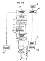
- a frequency generator (FG) 28 is used as the rotation angle sensor 12 for sensing rotation angle and rotation quantity of the shaft of the motor 1, instead of the rotary encoder 19.
- the frequency generator 28 is coupled with the shaft of the motor 1 so that the frequency generator 28 generates frequency signals in proportion to the rotation angle of the shaft of the motor 1.
- the frequency signals are inputted to the rotation angle calculator 13 via the waveform shaping circuit 20.
- the rotation angle calculator 13 calculates the rotation angle ⁇ r of the anvil 5 with using the following equation at each time when the microphone 16 serving as the impact sensor 11 senses the impact of the hammer 4.
- ⁇ r ⁇ RM / K - RI
- the symbol ⁇ RM designates a rotation angle of the shaft of the motor 1 while the hammer 4 impacts the anvil 5 each time
- the symbol K designates a reduction ratio of the reducer 2
- the symbol RI designates an idle angle of the hammer 4.
- the idle angle RI 2 ⁇ /3.
- the frequency generator 28 is used not only as the rotation angle sensor 12, but also as the impact sensor 11 instead of the microphone 16. Specifically, the rotation speed of the motor 1 is reduced a little due to load fluctuation when the hammer 4 impacts the anvil 5, and the pulse width of the frequency signal outputted from the frequency generator 28 becomes a little wider.
- An impact sensing processor 29 senses the variation of the pulse width of the frequency signal as the occurrence of the impact.
- the distance sensor 24 is further provided on the power impact tool as illustrated in FIG. 12. Since the modification of the power impact tool in this embodiment is not limited by the description and the illustration, it is possible to combine the features of the modifications, for example, the rotary encoder 19 serving as the rotation angle sensor 12 and the frequency generator 28 serving as the impact sensor 11. Furthermore, it is possible to use an acceleration sensor as the impact sensor 11.
- the reference rotation angle ⁇ R is defined as a value corresponding to the mean value T M of the torque T in several times of the impact from the start of the fastening operation, so that the reference rotation angle ⁇ R becomes suitable corresponding to a kind of the bolt.
- the fastening judger 21 judges that the bolt is made of harder material or the bolt is larger, and the reference rotation angle ⁇ R is set to be smaller.
- the fastening judger 21 judges that the bolt is made of softer material or the bolt is smaller, and the reference rotation angle ⁇ R is set to be larger. Consequently, the fastening operation corresponding to the kind of the bolt can be carried out.
- the judgment process of the completion of the fastening operation executed by the CPU can be made simple without using the torque variation quantity ⁇ t and the torque variation ratio ⁇ ⁇ T, so that the cost of the power impact tool can be reduced owing to the capacity of the RAM can be made smaller.
- FIG. 13 shows a modification of the fastening operation shown in FIG. 5.
- the fastening operation of the bolt is completed when the value of the reference index becomes equal to or larger than the threshold value of trouble judgment after the value of the torque variation ratio ⁇ ⁇ T has become substantially zero.
- the fastening operation of the bolt is completed when the value of the torque variation ratio ⁇ ⁇ T becomes substantially zero after the value of the reference index has become equal to or larger than the threshold value of trouble judgment.
- the steps S31 to S37 and S40 in FIG. 13 are the same as the steps S 1 to S7 and S10 in FIG. 5.
- the step S38 in FIG. 13 is substantially the same as the step S9 in FIG. 5.
- the step S39 in FIG. 13 is substantially the same as the step S8 in FIG. 5. Thus, detailed description of each step is omitted. By such the configuration, substantially the same effect as that of the above-mentioned embodiment shown in FIG. 5 can be obtained.
- FIG. 14 shows a modification of the fastening operation shown in FIG. 6.
- the steps S41 to S48, S52 and S53 in FIG. 14 are the same as the steps S11 to S18, S22 and S23 in FIG. 6.
- the step S49 in FIG. 14 is substantially the same as the step S20 in FIG. 6.
- the step S50 in FIG. 14 is substantially the same as the step S19 in FIG. 6.
- the power impact tool such as the impact wrench is described as an example of the fastening tool in accordance with the present invention.
- the present invention is not limited the embodiment. It is possible to apply the present invention to a non-impact fastening tool.
- a time period of the driving of the motor 1 can be sensed as the reference index instead of the number of the impacts.
- the present invention can be applied in the art of the power tool for fastening screw or bolt, by which the screw or the bolt can be fastened suitably corresponding to the material or the size of the screw or the bolt without loosening due to smaller fastening torque and without the damage due to larger fastening torque.
Description
- The present invention relates to a power tool such as an impact driver or an impact wrench used for fastening a screw or a bolt.
- A power tool according to the preamble of
claim 1 is known from EP 0264698. - Conventionally, a power tool used for fastening a screw or a bolt utilizing driving force of a motor has a function automatically stopping driving of the motor when a torque necessary for fastening the screw or the bolt reaches to a predetermined value due to the screw or the bolt is completely fastened.
- In a first conventional power tool such as an impact wrench used for fastening a bolt, for example, shown in publication gazette of Japanese Patent Application 4-322974, a number of impact of a hammer is sensed and driving of a motor is automatically stopped when the number of impact reaches to a predetermined reference number.
- In a second conventional power impact tool shown in publication gazette of Japanese Patent Application 9-285974, a rotation angle of a bolt is sensed and driving of a motor is stopped when the rotation angle reaches to a predetermined reference angle.
- In a third conventional power impact tool shown in publication gazette of Japanese Patent Application 6-91551, an actual torque which is necessary for fastening a bolt is sensed and driving of a motor is stopped when the actual torque reaches to a predetermined reference value.
- The first conventional power impact tool which stops the driving of the motor corresponding to the impact number and the second conventional power impact tool which stops the driving of the motor corresponding to the rotation angle respectively have a disadvantage that a large difference may occur between a desired torque and the actual torque for fastening the screw or the bolt. The difference causes loosening of the screw or the bolt due to insufficient torque when the actual torque is much smaller than the desired torque. Alternatively, the difference causes to damage the elements to be fastened by the screw or the bolt or to damage a head of the screw or the bolt due to superfluous torque when the actual torque is much larger than the desired torque.
- On the other hand, the third conventional power impact tool which stops the driving of the motor corresponding to the actual torque for fastening the screw or the bolt needs a sensor provided on an output shaft for sensing the actual torque, so that it causes the cost increase and the upsizing of the power impact tool, even though the automatic stopping of the driving of the motor can be controlled precisely corresponding to the actual torque.
- For solving the above-mentioned problems, in a fourth conventional power impact tool shown in publication gazette of Japanese Patent Application 2002-283248, a torque for fastening the bolt is estimated according to rotation speed of a shaft of a motor when an impact is applied to the bolt. It is judged that the bolt is completely fastened when the estimated torque is suddenly increased. The driving of the motor is stopped when the estimated torque is suddenly increased.
- In the fourth conventional power impact tool, there is a possibility that the driving of the motor is stopped before the bolt is fastened completely, when the torque is temporarily increased due to trouble in fastening operation. In order to prevent the stop of the driving of the motor before the bolt is fastened completely, a reference torque for judging occurrence of trouble is defined, which is a little larger than the largest torque when the torque is temporarily increased due to the trouble. While the estimated torque has not been equal to or larger than the reference torque for judging occurrence of trouble, the driving of the motor is continued, so that the occurrence of malfunction that the driving of the motor is stopped before the bolt is fastened completely can be prevented.
- As examples of cause of the trouble in the fastening operation, an irregularity of thread grooves of the bolt, a slight warp of a member interleaved between the bolt and the nut, decentering of the bolt or the nut, clipping of dust between the bolt and the nut, picking off of a surface coating of baking finish on the bolt, lifting of a member inter leaved between the bolt and the nut, are recited.
- In the fourth conventional power impact tool, it, however, is difficult to distinguish an instantaneous increase of the torque appeared in a variation of the torque due to the trouble in the fastening operation from the increase of the torque due to the bolt is fastened completely, since the variation of the torque while the bolt is fastened is irregular corresponding to combination of the bolt and the object to be fastened. Thus, there is a possibility that the driving of the motor is stopped before the bolt is fastened completely.
- A purpose of the present invention is to provide a power tool used for fastening a screw or a bolt, by which driving of a motor can surely be stopped just when the screw or the bolt is fastened completely.
- A power tool used for fastening a screw or a bolt in accordance with an aspect of the present invention comprises: a motor; a motor controller for controlling start and stop of driving of the motor; a power transmitter for transmitting driving force of the motor to a bit for fastening or loosening the screw or the bolt; a torque estimator for estimating a value of a torque for fastening the screw or the volt; and a fastening judger for judging whether the screw or the bolt is fastened completely or not.
- The fastening judger calculates a torque variation quantity Δ T which is a ratio of variation of the torque T with respect to a rotation angle of a shaft of the motor or elapsed time, and a torque variation ratio Δ Δ T which is a ratio of the torque variation quantity Δ T with respect to the rotation angle of the shaft of the motor or elapsed time. Subsequently, the fastening judger further calculates a reference index with using the torque variation ratio Δ Δ T, which is used for judging whether an increase of the value of the torque T is a temporary increase caused by a trouble in fastening operation or not. The fastening judger judges that the fastening operation is completed at least when the torque variation ratio Δ Δ T becomes substantially zero and the reference index becomes equal to or larger than a threshold value of trouble judgment, and outputs a signal for stopping the driving of the motor to the motor controller.
- Specifically, the fastening judger can judge that the fastening operation is completed when the torque variation ratio Δ Δ T becomes substantially zero after the reference index has become equal to or larger than the threshold value of trouble judgment.
- Alternatively, the fastening judger can judge that the fastening operation is completed when the reference index becomes equal to or larger than the threshold value of trouble judgment after the torque variation ratio has become substantially zero.
- According to such the configurations, it is possible surely to judge whether the increase of the torque is caused by the trouble or not with using peak curves of the torque variation ratio Δ Δ T.
- Furthermore, the driving of the motor is stopped a little before the torque for fastening the screw or the bolt becomes maximum value, so that it is especially suitable for fastening the screw or the bolt made of softer material or the smaller screw or the smaller bolt without damaging a head of the screw or the bolt.
- Furthermore, the fastening judger can judge that the fastening operation is completed when the value of the torque variation quantity Δ Δ T becomes substantially zero after the value of the reference index has become equal to or larger than the threshold value of trouble judgment first and the torque variation ratio has become substantially zero.
- Alternatively, the fastening judger can judge that the fastening operation is completed when the value of the torque variation quantity becomes substantially zero after the torque variation ratio has become substantially zero first and the value of the reference index has become equal to or larger than the threshold value of trouble judgment.
- According to such the configurations, the driving of the motor is stopped when the torque for fastening the screw or the bolt becomes substantially maximum value, so that it is especially suitable for fastening the screw or the bolt made of harder material or the larger screw or the larger bolt which is rarely damaged.
-
- FIG. 1 is a block diagram showing a configuration of a power impact tool, which is an embodiment of a power tool used for fastening a screw or a bolt in accordance with the present invention;
- FIG. 2 is a graph showing an example of variations of torque T, torque variation quantity Δ T and torque variation ratio Δ Δ T in the fastening operation;
- FIG. 3 is a graph showing an enlarged
peak curve S 1 in FIG. 2; - FIG. 4 is a graph showing differences between characteristics corresponding to materials or sizes of bolts, under the assumption that energy of impact of a hammer is the same;
- FIG. 5 is a flowchart showing a fastening operation of the power impact tool in the embodiment;
- FIG. 6 is a flowchart showing a modification of the fastening operation of the power impact tool in the embodiment;
- FIG. 7 is a graph showing a relation between a displacement of a trigger switch and a variation of voltage outputted from the trigger switch, and a relation between a first region and a second region in the power impact tool in the embodiment;
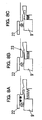
- FIGS. 8A to 8C are schematic sectional side views showing the displacement of the trigger switch;
- FIG. 9 is a schematic view of a displace sensor used in a modification of the power impact tool in the embodiment;
- FIG. 10 is a block diagram showing another modification of the power impact tool in the embodiment;
- FIG. 11 is a block diagram showing still another modification of the power impact tool in the embodiment;
- FIG. 12 is a block diagram showing still another modification of the power impact tool in the embodiment;
- FIG. 13 is a flowchart showing another modification of the fastening operation of the power impact tool in the embodiment; and
- FIG. 14 is a flowchart showing still another modification of the fastening operation of the power impact tool in the embodiment.
- A power tool used for fastening a screw or a bolt in accordance with an embodiment of the present invention is described. FIG. 1 shows a configuration of a power impact tool used for fastening a screw or a bolt as an example of the power tool in the embodiment.
- The power impact tool comprises a
motor 1 for generating a driving force, and apower transmitter 10 for transmitting the driving force of themotor 1 to abit 7 for fastening or loosening a screw or a bolt (hereinafter abbreviated as "bolt"). Thepower transmitter 10 further comprises areducer 2 for reducing rotation speed of a shaft of the motor 1 (hereinafter abbreviated as rotation speed of the motor 1), adriving shaft 3 connected to thereducer 2 and rotated by the driving force of themotor 1, ahammer 4 engaged with thedriving shaft 3 via a spline bearing, ananvil 5 engaged with thedriving shaft 3 with a clutch mechanism, and aspring 6 for applying pressing force to thehammer 4 toward theanvil 5. - The
hammer 4 can be moved in an axial direction of the drivingshaft 3 via the spline bearing, and rotated with thedriving shaft 3. The clutch mechanism is provided between thehammer 4 and theanvil 5. Thehammer 4 is pressed to theanvil 5 by the pressing force of thespring 6 in an initial state. Thebit 7 is detachable fitted to theanvil 5. Thus, thebit 7 can be rotated with thedriving shaft 3, thehammer 4 and theanvil 5 by the driving force of themotor 1. - A pair of cam faces is formed on, for example, an upper face of the
anvil 5 and a lower face of thehammer 4, which serve as the cam mechanism. For example, when the bolt has been fastened and the rotation of thebit 7 is stopped, the cam face on thehammer 4 slips on the cam face on theanvil 5 owing to the rotation with thedriving shaft 3 and thehammer 4 moves in a direction depart from theanvil 5 along the drivingshaft 3 following to the elevation of the cam faces against the pressing force of thespring 6. When thehammer 4 goes around, for example, substantially one revolution, the restriction due to the cam faces is suddenly released, so that thehammer 4 impacts theanvil 5 owing to charged pressing force of thespring 6 while it is rotated with thedriving shaft 3. Thus, a powerful fastening force can be applied to thebit 7 via theanvil 5, since the mass of thehammer 4 is much larger than that of theanvil 5. By repeating the impact of thehammer 4 against theanvil 5 in the rotation direction, the bolt can be fastened completely with a necessary fastening torque. - The
motor 1 is driven by amotor driver 8 so as to start and stop the rotation of the shaft. Themotor driver 8 is further connected to amotor controller 30, to which a signal corresponding to a displacement (pressing depth) of atrigger switch 9 is inputted. Themotor controller 30 judges user's intention to start or to stop the driving of themotor 1 corresponding to the signal outputted from thetrigger switch 9, and outputs a control signal for starting or stopping the driving of themotor 1 to themotor driver 8. - The
motor driver 8 is constituted as an analogous power circuit using a power transistor, and so on for supplying large electric current to themotor 8 stably. Arechargeable battery 32 is connected to themotor driver 8 for supplying electric power to themotor 1. On the other hand, themotor controller 30 is constituted by, for example, a CPU (Central Processing Unit), a ROM (Read Only Memory) and a RAM (Random Access Memory) for generating the control signals corresponding to a control program. - The power impact tool further comprises an
impact sensor 11 for sensing that the impact of thehammer 4 against theanvil 5 is carried out, arotation angle sensor 12 for sensing the rotation angle of theanvil 5, arotation angle calculator 13 for calculating a rotation angle Δ r of theanvil 5 per one impact of thehammer 4 with using outputs of theimpact sensor 11 and therotation angle sensor 12, and atorque estimator 14 for estimating a torque for fastening the bolt with using the rotation angle Δ r. These elements constitute a means for estimating the torque for fastening the bolt. - Specifically, the
impact sensor 11 is amicrophone 16 for sensing impact boom generated when thehammer 4 impacts theanvil 5 as a variation of voltage. Therotation angle sensor 12 is arotary encoder 19 constituted by adisc 17 rotated with theanvil 5 and having slits and a transmission photo-interrupter 18 for sensing the rotation angle of thedisc 17. Thus, the rotation angle of theanvil 5 is sensed as pulse signals. Themicrophone 16 and therotary encoder 19 are respectively connected to awaveform shaping circuit 20 so as to be executed the filtering process, and the processed signals by thewaveform shaping circuit 20 are inputted to therotation angle calculator 13. - The
rotation angle calculator 13 serially calculates the rotation angles Δ r of theanvil 5 per one impact of thehammer 4, and thetorque estimator 14 serially estimates the torque T for fastening the bolt. Since the calculation of the torque T is described in the above-mentioned publication gazette of Japanese Patent Application 2002-283248 in detail, the description of the calculation of the torque T is made simple. The torque T is calculated by the following equation showing the relation that the energy applied by the impact is substantially equal to the energy exhausted in the fastening of the bolt.
- Hereupon, the symbol T designates the torque for fastening the bolt, the symbol J designates the moment of inertia of the
anvil 5, and the symbol ω designates the rotation speed of theanvil 5 when the impact of thehammer 4 is carried out. - With respect to the rotation speed ω of the
anvil 5, the rotation speed of themotor 1 can be known according to the voltage of therechargeable battery 32 and the duty in PWM (Pulse Width Modulation) control while the electric current is supplied to themotor 1, and an approximate value of the rotation speed ω of theanvil 5 can be calculated by executing division of the rotation speed of themotor 1 by the reduction ratio K of thereducer 2. By substituting the rotation angle Δ r of theanvil 5 per one impact into the above-mentioned equation, the estimated torque can be calculated. - The power impact tool further comprises a
fastening judger 21 which calculates a torque variation quantity Δ T and a torque variation ratio Δ Δ T from the estimated torque T calculated by thetorque estimator 14 and judges whether the fastening operation of the bolt is completed or not. The torque variation quantity Δ T corresponds to a ratio of the variation of the torque T for fastening the bolt with respect to the rotation angle of the shaft of themotor 1 or elapsed time. The torque variation ratio Δ Δ T corresponds to a ratio of the variation of the torque variation quantity Δ T with respect to the rotation angle of themotor 1 or elapsed time. - For obtaining the torque variation quantity Δ T and the torque variation ratio Δ Δ T, it is possible to calculate a difference between a value calculated in this time and a value previously calculated, simply. It, however, is preferable to calculate a difference between a mean value among a first predetermined number of values of the estimated torque T and the torque variation quantity Δ T and another mean value among a second predetermined number of the values of them, in order to comprehend the variations of the torque T or the torque variation quantity Δ T in their entirety. Specifically, the torque variation quantity Δ T is a difference between a mean value among four values of the estimated torque T and another mean value among sixteen values of the estimated torque T. Similarly, the torque variation ratio Δ Δ T is a difference between a mean value among two values of the torque variation quantity Δ T and another mean value among eight values of the torque variation quantity Δ T.
- The
fastening judger 21 calculates the above-mentioned torque variation quantity Δ T and the torque variation ratio Δ Δ T. Furthermore, thefastening judger 21 judges that the fastening operation is completed at least when a number of the impact of thehammer 4 occurred in a term in which the torque variation ratios Δ Δ T continuously take positive values becomes larger than a predetermined threshold value of trouble judgment and the torque variation ratio Δ Δ T becomes substantially zero. When thefastening judger 21 judges that the fastening operation is completed, the fastening judger outputs a signal showing that the bolt has been fastened completely to themotor controller 30. Themotor controller 30 outputs a control signal for stopping the driving of the motor to themotor driver 8 when it receives the signal from thefastening judger 21. - FIG. 2 shows an example of the variations of the torque T, the torque variation quantity Δ T and the torque variation ratio Δ Δ T in the fastening operation of the bolt. As can be seen from FIG. 2, a peak P3 appears on a curve designated by a symbol T showing the variation of the torque T, after the bolt has been fastened completely. A peak curve S3 designated by a symbol Δ Δ T showing the variation of the torque variation ratio Δ Δ T appears a little before the appearance of the peak P3. It is possible to judge that the bolt has been fastened completely when the peak curve S3 appears. Generally, peaks P1, P2 and so on appear on the curve T due to the above-mentioned troubles in the fastening operation of the bolt, and peak curves S1, S2 and so on further appear correspondingly. The appearance of the peak curves
S 1, S2, and so on causes malfunction that the driving of themotor 1 has been stopped before the bolt is fastened completely. - In this embodiment, it is noticed that the peak values of the peak curves
S 1 and S2 due to the troubles are lower than that of the peak curve S3 due to the bolt is fastened completely, so that the number of the impact of the hammer 4 (N11-N10 and N21-N20) occurred due to the trouble in a terms in which the torque variation ratios Δ Δ T continuously take positive values is smaller than the number of the impact of the hammer 4 (N31-N30) due to the bolt is fastened completely. The above-mentioned predetermined threshold value of trouble judgment is defined to be larger than the value of the impact of thehammer 4 due to the trouble and smaller than that due to the bolt is fastened completely. Thus, it is possible surly to stop the driving of the motor when the torque for fastening the bolt is increased due to the bolt has been fastened completely without malfunction caused by the increase of the torque due to the trouble. - The
fastening judger 21 uses the number of the impact of thehammer 4 in the term in which the torque variation ratios Δ Δ T continuously take positive values as a reference index for judging whether the increase of the torque T for fastening the bolt is caused by the trouble or not. Since the value according to the torque variation ratio Δ Δ T is adopted as the reference index, the cause of the increase of the torque for fastening the bolt can precisely be judged with using the peak curves S1, S2, S3 ... of the torque variation ratio Δ Δ T. The reference index is not limited to the number of the impact of thehammer 4. It is possible to use the time period of the term in which the torque variation ratios Δ Δ T continuously take positive values as the reference index. - Furthermore, the threshold value of trouble judgment is not necessarily defined as a predetermined value. It is possible to define a value calculated from a maximum value of the torque variation ratio Δ Δ TMAX as the threshold value of trouble judgment. FIG. 3 shows an example of specific values of the torque variation ratio Δ Δ T and the impact number of the
hammer 4 with respect to the peak curve S1. For example, the threshold value of trouble judgment can be calculated as a value in proportion to the maximum vale of the torque variation ratio Δ Δ TMAX (Δ Δ TMAX × C1 (constant value)). In such the case, the value Δ Δ T103 corresponds to the maximum vale of the torque variation ratio Δ Δ TMAX in the case shown in FIG. 3, so that the threshold value of trouble judgment is calculated as Δ Δ T103 × C1. The calculated threshold value of trouble judgment (Δ Δ T 103 × C1) is compared with the number of impact of the hammer 4 (N11-N10) as the reference index. When (N11-N10) > (Δ Δ T 103 × C1), thefastening judger 21 judges that the fastening operation of the bolt has been completed. Alternatively, when (N11-N10) ≦ (Δ Δ T 103 × C1), thefastening judger 21 judges that the torque has been increased due to a temporary trouble. By such a configuration, even when a large torque variation ratio Δ Δ T instantaneously appears due to trouble, the number of impact of thehammer 4 is smaller (or the time period of the peak curve is shorter) in proportion to the intensity of the torque variation ratio Δ Δ T. Thus, it is possible to judge the increase of the torque variation ratio Δ Δ T is caused by the trouble, so that malfunction that the driving of themotor 1 has been stopped before the bolt is completely fastened can be prevented. - Alternatively, it is possible to adopt a sum ∑ (Δ Δ T) of values of the torque variation ratios Δ Δ T occurred at each impact of the
hammer 4 in a term in which the torque variation ratios Δ Δ T take positive values as the reference index. It is noticed that the sum ∑ ( A Δ T) of values of the torque variation ratios Δ Δ T occurred at each impact of thehammer 4 in the term in which the torque variation ratios Δ Δ T take positive values due to the trouble becomes smaller than that due to the bolt is fastened completely, since the peak values of the peak curvesS 1 and S2 due to the trouble are lower than that of the peak curve S3 due to the bolt is fastened completely. In this case, the threshold value of trouble judgment is defined to be larger than the sum ∑ ( A ΔT) of values of the torque variation ratios Δ Δ T due to the trouble and smaller than the sum ∑ (Δ Δ T) of values of the torque variation ratios Δ Δ T due to the bolt is fastened completely. Thus, it is possible to stop the driving of themotor 1 just when the bolt is fastened completely without malfunction when the torque variation ratio Δ Δ T is increased due to the trouble. In the case shown in FIG. 3 which illustrates thepeak curve S 1 largely, the sum ∑(Δ ΔT)=Δ ΔT10+Δ Δ T101+Δ Δ T102+•••+Δ Δ T11. The reference index is not limited to the sum ∑ ( Δ Δ T) of values of the torque variation ratios Δ Δ T occurred at each impact of thehammer 4 in the term in which the torque variation ratios Δ Δ T take positive values. It is possible to use a value of integration of the torque variation ratio Δ Δ T in the term in which the torque variation ratios Δ Δ T continuously take positive values as the reference index. - In this case, the threshold value of trouble judgment is not necessarily defined as a predetermined value. It is possible to define a value calculated from a maximum value of the torque variation ratio Δ Δ TMAX as the threshold value of trouble judgment. For example, when the threshold value of trouble judgment can be calculated as a value in proportion to the maximum value of the torque variation ratio Δ Δ TMAX (Δ Δ TMAX × C2(constant value)), the threshold value of trouble judgment is calculated as Δ Δ T103 × C2. The calculated threshold value of trouble judgment (Δ Δ T103 × C2) is compared with the sum ∑ ( Δ Δ T) as the reference index. When ∑ (Δ Δ T) > ( Δ Δ T103 × C2), the
fastening judger 21 judges that the fastening operation of the bolt has been completed. Alternatively, when ∑ (Δ Δ T) ≦ ( Δ Δ T103 × C2), thefastening judger 21 judges that the torque has been increased due to a temporary trouble. By such a configuration, even when a large torque variation ratio Δ Δ T instantaneously appears due to the trouble, the sum ∑ ( Δ Δ T) of the torque variation ratio Δ Δ T occurred at each impact of thehammer 4 is smaller in proportion to the intensity of the torque variation ratio Δ Δ T. Thus, it is possible to judge the increase of the torque variation ratio Δ Δ T is caused by the trouble, so that malfunction that the driving of themotor 1 is stopped before the bolt is fastened completely can be prevented. - Still furthermore, it is possible to define the threshold value of trouble judgment as a value calculated from an initial value of the torque T in the fastening operation of the bolt. FIG. 4 shows differences between characteristics corresponding to the materials or the sizes of the bolts, under the assumption that the energy of impact of the
hammer 4 is the same. As can be seen from FIG. 4, when the material of the bolt is harder, the torque T for fastening the bolt per one impact of thehammer 4 becomes larger. Alternatively, when the material of the bolt is softer or the size of the bolt is smaller, the torque T for fastening the bolt per one impact of thehammer 4 becomes smaller. Since such a tendency carries from the start to the completion of the impact operation of the hammer, it is noticed that the torque T for fastening the bolt becomes entirely smaller, and the torque variation quantity Δ T and the torque variation ratio Δ Δ T further become entirely smaller when the torque T at the initial state of the impact operation of thehammer 4. Thus, it is possible to judge that the bolt has been fastened completely without misjudging caused by the increase of the torque due to the trouble with no relation to the kinds of the bolts, when the threshold value of trouble judgment is defined to be a value in proportion to a mean value of the estimated values of the torque T in several times of the impact from the start of the fastening operation of the bolt. - Still furthermore, it is possible to use the value of the torque variation ratio Δ Δ T itself as the reference index, and to define the threshold value of trouble judgment as a value calculated from the value of the torque T at the initial state of the fastening operation of the bolt. It is noticed that the torque T, the torque variation quantity Δ T and the torque variation ratio Δ Δ T further become entirely smaller when the torque T at the initial state of the fastening operation of the bolt. Thus, it is possible to judge that the bolt has been fastened completely without misjudging caused by the increase of the torque due to the trouble with no relation to the kinds of the bolts, when the threshold value of trouble judgment is defined to be a value in proportion to a mean value of the estimated values of the torque T in several times of the impact from the start of the fastening operation of the bolt.
- Subsequently, the fastening operation of the power impact tool is described. FIG. 5 shows a basic flow of the fastening operation of the bolt in this embodiment, in which the fastening operation of the bolt is completed when the value of the reference index becomes larger than the threshold value of trouble judgment after the value of the torque variation ratio Δ Δ T becomes substantially zero.
- When the user operates the
trigger switch 9, themotor controller 30 outputs a control signal for starting the driving of themotor 1 so as to fasten the bolt. Theimpact sensor 11 starts to sense the occurrence of the impact of the hammer 4 (S1). When theimpact sensor 11 senses the occurrence of the impact (Yes in S2), therotation angle calculator 13 calculates the rotation angle Δ r of theanvil 5 while thehammer 4 impacts the anvil 5 (S3). Therotation angle calculator 13 further calculates the rotation speed ω of theanvil 5 at the occurrence of the impact (S4). When the rotation angle Δ r and the rotation speed ω are calculated, thetorque estimator 14 calculates the torque T according to the above-mentioned equation (S5). Thefastening judger 21 calculates the torque variation quantity Δ t and the torque variation ratio Δ Δ T (S6 and S7). Subsequently, thefastening judger 21 judges whether the value of the torque variation ratio Δ Δ T has changed from positive to negative or not (S8). When the value of the torque variation ratio Δ Δ T from positive to negative, that is, the value of the torque variation ratio Δ Δ T has become substantially zero, thefastening judger 21 further judges whether the value of the reference index becomes equal to or larger than the threshold value of trouble judgment or not (S9). When the value of the reference index is not equal to or larger than the threshold value of trouble judgment, thefastening judger 21 judges that the increase of the torque T is due to the trouble, and returns to thestep S 1. Alternatively, when the value of the reference index becomes equal to or larger than the threshold value of trouble judgment, thefastening judger 21 judges that the increase of the torque T is due to the bolt has been fastened completely, and executes the stopping process for stopping the driving of the motor 1 (S10). - In reference to FIG. 2, the driving of the
motor 1 is stopped when the torque variation ratio Δ Δ T becomes substantially zero, which is designated by a symbol N31. The peak P3 of the torque T, however, appears after the torque variation ratio Δ Δ T becomes substantially zero, which is designated by, for example, a symbol N32. In other words, the fastening operation of the bolt has been completed a little before the torque T for fastening the bolt takes the maximum value. Thus, this example is suitable for the bolt made of softer material or the smaller bolt, which can easily be damaged by superfluous torque in the fastening operation. - Thus, a modified operation of the power impact tool is described. FIG. 6 shows a modified flow of the impact sensing operation in this embodiment, in which the fastening operation of the bolt is completed when the value of the torque variation quantity Δ T becomes substantially zero after the torque variation ratio Δ Δ T has become substantially zero first and the value of the reference index has become equal to or larger than the threshold value of trouble judgment. In the flow shown in FIG. 6, the steps from S11 to S17 are substantially the same as the steps from
S 1 to S7 in the flow shown in FIG. 5, so that the description of them are omitted. - After the
fastening judger 21 has calculated the torque variation quantity Δ t and the torque variation ratio Δ Δ T (S16 and S 17), thefastening judger 21 judges whether a stopping flag for executing stopping process has been turned on or not (S 18). Generally, the stopping flag has not been turned on, so that thefastening judger 21 judges whether the value of the torque variation ratio Δ Δ T has changed from positive to negative or not (S 19). When the value of the torque variation ratio Δ Δ T has changed from positive to negative, thefastening judger 21 further judges whether the value of the reference index becomes equal to or larger than the threshold value of trouble judgment or not (S20). When the value of the reference index is not equal to or larger than the threshold value of trouble judgment, thefastening judger 21 judges that the increase of the torque T is due to the trouble, and returns to thestep S 11. Alternatively, when the value of the reference index is equal to or larger than the threshold value of trouble judgment, thefastening judger 21 judges that the increase of the torque T is due to the bolt has been fastened substantially completely, turns on the stopping flag for executing the stopping process (S21), and returns to thestep S 11. - When the flow returns to the
step S 11, the steps S12 toS 18 are executed again. In the step S 18 second accession, since the flag has been turned on, thefastening judger 21 judges whether the value of the torque variation quantity Δ T has changed from positive to negative or not (S22). When the value of the torque variation quantity Δ T has changed from positive to negative, thefastening judger 21 judges that the increase of the torque T is due to the bolt has been fastened completely, and executes the stop operation for stopping the driving of the motor 1 (S23). Alternatively, when the value of the torque variation quantity Δ T has not changed from positive to negative, thefastening judger 21 judges that the bolt has not been fastened completely, and returns to the step S 11 so as to repeat the above-mentioned processes. - In the latter case, the
motor 1 is further driven after the torque variation ratio Δ Δ T becomes substantially zero, so that the bolt can be fastened by substantially the maximum value of the torque. Thus, this modification is suitable for the bolt made of harder material or the larger bolt, which is rarely damaged by the superfluous torque in the fastening operation. - The above-mentioned two-types of the fastening control can be switched by operation of the user (operation switch is not illustrated), so that it is possible to carry out the fastening operation corresponding to the characteristics of the object to be fastened. Alternatively, it is possible to switch the above-mentioned two-types of the fastening control automatically corresponding to the value of the torque T when the torque variation ratio Δ Δ T becomes substantially zero. Specifically, the
fastening judger 21 judges whether the value of the torque T is larger than a predetermined reference value or not when the torque variation ratio Δ Δ T becomes substantially zero. When the value of the torque T is not larger than the predetermined reference value, thefastening judger 21 judges that the fastening operation of a bolt made of softer material or a smaller bolt has been completed, and themotor controller 30 outputs a control signal for stopping the driving of themotor 1 to themotor driver 8. Alternatively, when the value of the torque T is larger than the predetermined reference value, thefastening judger 21 further judges whether the torque variation quantity Δ T becomes zero, or not. When the torque variation quantity Δ T becomes zero, thefastening judger 21 judges that the fastening operation of a bolt made of harder material or a larger bolt has been completed, and themotor controller 30 outputs a control signal for stopping the driving of themotor 1 to themotor driver 8. - Subsequently, a modification of the power impact tool in this embodiment is described. It is possible that the
motor controller 30 and themotor driver 8 serve as an automatic speed controller for adjusting the rotation speed of themotor 1 corresponding to the torque T for fastening the bolt in the initial state of the fastening operation. For example, themotor controller 30 compares a mean value of the estimated values of the torque T at several times of the impact of thehammer 4 from the start of the fastening operation with a predetermined reference value. When the mean value of the torque T is smaller than the reference value, themotor controller 30 judges that the bolt made of softer or the smaller bolt is fastened, and outputs a signal for reducing the rotation speed of themotor 1 to themotor driver 8. Thus, it is possible to reduce the energy of the impact by reducing the rotation speed of themotor 1 when the bolt made of the softer material or the smaller bolt, which can be damaged easily, is fastened. - Since the energy of the impact is reduced, the number of the impacts necessary for completing the fastening of the bolt increases, so that the quantity of the data used for judging that the bolt is completely fastened in the
fastening judger 21. Thus, it becomes easy to judge the completion of the fastening of the bolt, precisely. Furthermore, it is preferable that the control signal outputted from themotor controller 30 makes the rotation speed of themotor 1 slower corresponding to the degree of the value of the torque T in the initial state. Specifically, a desired value VD of the rotation speed of themotor 1 is to be in proportion to the mean value VM of the estimated values of the torque T in several numbers of the impacts from the start of the impact operation. The value VD is, for example, calculated by the following equation.
- Hereupon, the symbol VN designates the rotation speed of the
motor 1 at the present, and the symbol C3 designates a constant. When the desired value VD becomes larger than the rotation speed VN at the present, that is, when the rotation speed of themotor 1 is necessary to be increased, the rotation speed of themotor 1 should be maintained as it is (VD=VN). By such the configuration, the degree of the reduction of the rotation speed of themotor 1 can be made minimum, so as to prevent the large extension of the working time of the fastening operation due to the reduction of the rotation speed of themotor 1. - In other words, the
motor controller 30 and themotor driver 8 serving as the automatic speed controller controls themotor 1 in a manner so that the smaller the torque in the initial state of the fastening operation is, the slower the rotation speed of themotor 1 becomes. - Another modification of the power impact tool in this embodiment is described with reference to FIGS. 7 and 8A to 8C. As shown in FIG. 7, a stroke of the
trigger switch 9 is divided into a first region and a second region so as to assure the fastening operation of the bolt. In the first region of the stroke of thetrigger switch 9, the output of the control signal for stooping the driving of themotor 1 is restricted, and in the second region of the stroke of thetrigger switch 9, the output of the control signal for stooping the driving of themotor 1 is permitted, even when thefastening judger 21 judges that the bolt has been fastened completely. - As shown in FIGS. 8A to 8C, the
trigger switch 9 is connected to avariable resistor 22 so that the displacement of thetrigger switch 9 is converted to the variation of the voltage. A section from point A to point C in FIG. 7 is a mechanical allowance, in which the electric power is not supplied to themotor 1. A section from point C to point D in FIG. 7 is a speed control region, in which the rotation speed of themotor 1 is increased corresponding to increase of the displacement of thetrigger switch 9. A section from point D to point B in FIG. 7 is a constant speed region, in which the rotation speed of themotor 1 is maintained as the maximum speed. The boundary between the first region and the second region is selected at point E in the section from the point D to the point B. The first region is defined as the left side from the point E, in which the displacement of thetrigger switch 9 is smaller than a predetermined value at the point E. The second region is defined as the right side from the point E, in which the displacement of thetrigger switch 9 is equal to or larger than a predetermined value at the point E. - Accordingly, the user can carry out the fastening operation of the bolt with adjusting the rotation speed of the
motor 1 in the first region including the speed control region until the user confirms the bolt is fastened by visual observation. Subsequently, the user can continue the fastening operation with pushing thetrigger switch 9 into the second region after observing the bolt is in a state just before it is completely fastened. By such a configuration, the fastening operation of the bolt can surely be completed without stopping the driving of the motor before the bolt is completely fastened, even when thefastening judger 21 has erroneously judged the bolt has been fastened completely due to the trouble. Aclick mechanism 23 is provided for applying a feel to the user when thetrigger switch 9 reaches to the point E, so that the user can easily recognize the transition from the first region to the second region. - Still another modification of the power impact tool in this embodiment is described with reference to FIG. 9. It is possible to use a
distance sensor 24 for sensing a distance to a face of anobject 27 to be fastened by the bolt. Thedistance sensor 24 comprises alight emitting device 25 and a photo-sensingdevice 26. A light beam emitted from thelight emitting device 25 is focused on theobject 27 by a lens (not shown), and a reflected beam from theobject 27 is received by the photo-sensingdevice 26, so that the distance to theobject 27 from thedistance sensor 24 can be sensed. Thedistance sensor 24 compares a measurement result of a distance to theobject 27 with a predetermined reference distance, and outputs a sensing signal when the measurement result is shorter than the reference distance. - The
distance sensor 24 is provided at a stationary portion of the power impact tool in the vicinity of thebit 7. For example, a distance, which is a little longer than a distance from thedistance sensor 24 to a surface of theobject 27 when the bolt is completely fastened, is defined as the reference distance. Thus, the sensing signal can be outputted from thedistance sensor 24 just before the bolt is actually fastened completely. While the sensing signal has not been outputted, no control signal for stopping the driving of themotor 1 is outputted from themotor controller 30 to themotor driver 8, even when thefastening judger 21 has erroneously judged the bolt has been fastened completely. Alternatively, while the sensing signal has been outputted, a control signal for stopping the driving of themotor 1 can be outputted from themotor controller 30 to themotor driver 8, when thefastening judger 21 has judged the bolt has been fastened completely. By such a configuration, it is possible to carry out the fastening operation of the bolt easily without stopping the driving of themotor 1 before the bolt is actually fastened completely. Furthermore, the user can be gut off from the visible observation to confirm the bolt has been fastened substantially completely. - Still other modifications not forming part of the invention of the power impact tool are described with reference to FIGS. 10, 11 and 12. In the modification shown in FIG. 10, a frequency generator (FG) 28 is used as the
rotation angle sensor 12 for sensing rotation angle and rotation quantity of the shaft of themotor 1, instead of therotary encoder 19. Thefrequency generator 28 is coupled with the shaft of themotor 1 so that thefrequency generator 28 generates frequency signals in proportion to the rotation angle of the shaft of themotor 1. The frequency signals are inputted to therotation angle calculator 13 via thewaveform shaping circuit 20. Therotation angle calculator 13 calculates the rotation angle Δ r of theanvil 5 with using the following equation at each time when themicrophone 16 serving as theimpact sensor 11 senses the impact of thehammer 4.
- Hereupon, the symbol Δ RM designates a rotation angle of the shaft of the
motor 1 while thehammer 4 impacts theanvil 5 each time, the symbol K designates a reduction ratio of thereducer 2, and the symbol RI designates an idle angle of thehammer 4. For example, when thehammer 4 impacts theanvil 5 twice in one revolution of thehammer 4, the idle angle RI=2 π /2= π. When thehammer 4 impacts theanvil 5 thrice in one revolution of thehammer 4, the idle angle RI=2 π /3. - In the modification shown in FIG. 11, the
frequency generator 28 is used not only as therotation angle sensor 12, but also as theimpact sensor 11 instead of themicrophone 16. Specifically, the rotation speed of themotor 1 is reduced a little due to load fluctuation when thehammer 4 impacts theanvil 5, and the pulse width of the frequency signal outputted from thefrequency generator 28 becomes a little wider. Animpact sensing processor 29 senses the variation of the pulse width of the frequency signal as the occurrence of the impact. - It is possible that the
distance sensor 24 is further provided on the power impact tool as illustrated in FIG. 12. Since the modification of the power impact tool in this embodiment is not limited by the description and the illustration, it is possible to combine the features of the modifications, for example, therotary encoder 19 serving as therotation angle sensor 12 and thefrequency generator 28 serving as theimpact sensor 11. Furthermore, it is possible to use an acceleration sensor as theimpact sensor 11. - Still furthermore, a modification of a method not forming part of the invention for judging that the bolt has been fastened completely in the power impact tool is described. It is possible to judge that the fastening operation of the bolt has been completed when the rotation angle of the bolt attains to a predetermined reference rotation angle θR. The control signal for stopping the driving of the
motor 1 is outputted from themotor controller 30 to themotor driver 8 when it is judged that the fastening operation has been completed. The reference rotation angle θ R is defined as a value corresponding to the mean value TM of the torque T in several times of the impact from the start of the fastening operation, so that the reference rotation angle θ R becomes suitable corresponding to a kind of the bolt. Specifically, the reference rotation angle θ R is obtained as a division of the mean value TM of the torque T and a constant C4 ( θ R=TM/C4). - According to the above-mentioned judging process, when the mean value TM of the torque T in the initial state of the fastening operation of the bolt is larger, the
fastening judger 21 judges that the bolt is made of harder material or the bolt is larger, and the reference rotation angle θ R is set to be smaller. Alternatively, when the mean value TM of the torque T in the initial state of the fastening operation is smaller, thefastening judger 21 judges that the bolt is made of softer material or the bolt is smaller, and the reference rotation angle θ R is set to be larger. Consequently, the fastening operation corresponding to the kind of the bolt can be carried out. Furthermore, the judgment process of the completion of the fastening operation executed by the CPU can be made simple without using the torque variation quantity Δ t and the torque variation ratio Δ Δ T, so that the cost of the power impact tool can be reduced owing to the capacity of the RAM can be made smaller. - Subsequently, modifications of the fastening operation of the power impact tool are described with reference to FIGS. 13 and 14. FIG. 13 shows a modification of the fastening operation shown in FIG. 5. In the above-mentioned flow shown in FIG. 5, the fastening operation of the bolt is completed when the value of the reference index becomes equal to or larger than the threshold value of trouble judgment after the value of the torque variation ratio Δ Δ T has become substantially zero. On the other hand, in the flow shown in FIG. 13, the fastening operation of the bolt is completed when the value of the torque variation ratio Δ Δ T becomes substantially zero after the value of the reference index has become equal to or larger than the threshold value of trouble judgment.
- In comparison with FIG. 13 and FIG. 5, the steps S31 to S37 and S40 in FIG. 13 are the same as the steps S 1 to S7 and S10 in FIG. 5. The step S38 in FIG. 13 is substantially the same as the step S9 in FIG. 5. The step S39 in FIG. 13 is substantially the same as the step S8 in FIG. 5. Thus, detailed description of each step is omitted. By such the configuration, substantially the same effect as that of the above-mentioned embodiment shown in FIG. 5 can be obtained.
- Similarly, FIG. 14 shows a modification of the fastening operation shown in FIG. 6. In comparison with FIG. 14 and FIG. 6, the steps S41 to S48, S52 and S53 in FIG. 14 are the same as the steps S11 to S18, S22 and S23 in FIG. 6. The step S49 in FIG. 14 is substantially the same as the step S20 in FIG. 6. The step S50 in FIG. 14 is substantially the same as the step S19 in FIG. 6. By such the configuration, substantially the same effect as that of the above-mentioned embodiment shown in FIG. 6 can be obtained.
- In the above-mentioned embodiment, the power impact tool such as the impact wrench is described as an example of the fastening tool in accordance with the present invention. The present invention, however, is not limited the embodiment. It is possible to apply the present invention to a non-impact fastening tool. In case of non-impact fastening tool, a time period of the driving of the
motor 1 can be sensed as the reference index instead of the number of the impacts. - As mentioned above, the present invention can be applied in the art of the power tool for fastening screw or bolt, by which the screw or the bolt can be fastened suitably corresponding to the material or the size of the screw or the bolt without loosening due to smaller fastening torque and without the damage due to larger fastening torque.
Claims (16)
- A power tool used for fastening a screw or a bolt comprising: a motor (1); a motor controller (8, 30) for controlling start and stop of driving of the motor; a power transmitter (10) for transmitting driving force of the motor to a bit (7) for fastening or loosening a screw or a bolt; a torque estimator (14) for estimating a value of a torque for fastening the screw or the bolt; and a fastening judger (21) for judging whether the screw or the bolt is fastened completely or not; characterised in that
the fastening judger (21)
calculates a torque variation quantity which is a ratio of variation of the torque with respect to a rotation angle of a shaft of the motor (1) or to a elapsed time, and a torque variation ratio which is a ratio of the variation of the torque variation quantity with respect to the rotation angle of the shaft of the motor or elapsed time;
calculates a reference index with using the torque variation ratio, which is used for judging whether an increase of the value of the torque is temporary increase caused by a trouble in fastening operation or not;
judges that the fastening operation is completed at least when the torque variation ratio becomes substantially zero and the reference index becomes equal to or larger than a threshold value of trouble judgment; and
outputs a signal for stopping the driving of the motor to the motor controller. - The power tool in accordance with claim 1, wherein
the fastening judger (21) judges that the fastening operation is completed when the torque variation ratio becomes substantially zero after the reference index has become equal to or larger than the threshold value of trouble judgment. - The power tool in accordance with claim 1, wherein
the fastening judger (21) judges that the fastening operation is completed when the value of the torque variation quantity becomes substantially zero after the torque variation ratio has become substantially zero first and the value of the reference index has become equal to or larger than the threshold value of trouble judgment. - The power tool in accordance with claim 1, wherein
the fastening judger (21) judges that the fastening operation is completed when the reference index becomes equal to or larger than the threshold value of trouble judgment after the torque variation ratio has become substantially zero. - The power tool in accordance with claim 1, wherein
the fastening judger (21) judges that the fastening operation is completed when the value of the torque variation quantity becomes substantially zero after the value of the reference index has become equal to or larger than the threshold value of trouble judgment first and the torque variation ratio has become substantially zero. - The power tool in accordance with one of claims 1 to 5, wherein
the reference index is a time period in a term in which the torque variation ratios take positive values. - The power tool in accordance with one of claims 1 to 5, wherein
the reference index is a number of impact of a hammer (4) in a term in which the torque variation ratios take positive values when the power tool is a power impact tool. - The power tool in accordance with one of claims 1 to 5, wherein
the reference index is an integration value of the torque variation ratio in a term in which the torque variation ratios take positive values. - The power tool in accordance with one of claims 1 to 5, wherein
the reference index is a sum of values of the torque variation ratios occurred at each impact of a hammer (4) in a term in which the torque variation ratios take positive values when the power tool is a power impact tool. - The power tool in accordance with one of claims 1 to 5, wherein
the threshold value of trouble judgment is calculated with using a maximum value of the torque variation ratio in a term in which the torque variation ratios take positive values. - The power tool in accordance with one of claims 1 to 5, wherein
the threshold value of trouble judgment is calculated with using a value of the torque in an initial state of the fastening operation. - The power tool in accordance with one of claims 1 to 5, wherein
the reference index is a value relating to the torque variation ratio, and the threshold value of trouble judgment is calculated with using a value of the torque in an initial state of the fastening operation. - The power tool in accordance with one of claims 1 to 5 further comprising:an automatic speed controller for reducing rotation speed of the shaft of the motor when the torque in an initial state of the fastening operation is smaller than a predetermined reference value of the torque.
- The power tool in accordance with claim 13, wherein
the automatic speed controller (21, 30, 8) controls the motor (1) in a manner so that the smaller the torque in the initial state of the fastening operation is, the slower the rotation speed of the shaft of the motor (1) becomes. - The power tool in accordance with one of claims 1 to 5 further comprising:a trigger switch (9, 22) operated by a user and outputting signals for controlling at least start and stop of the driving of the motor (1) corresponding to a displacement thereof; and whereina stroke of the trigger switch is divided into a first region in which the motor controller is restricted to stop the driving of the motor, and a second region in which the motor controller is admitted to stop the driving of the motor (FIG. 7).
- The power tool in accordance with one of claims 1 to 5 further comprising:a distance sensor (24) for sensing a distance to a face (27) to which a head of the screw or the bolt is tightly fastened; and whereinthe motor controller (8, 30) stops the driving of the motor (1) after the distance sensed by the distance sensor (24) reaches to a reference distance for judging the screw or the bolt has been fastened completely.
Applications Claiming Priority (2)
| Application Number | Priority Date | Filing Date | Title |
|---|---|---|---|
| JP2003301899 | 2003-08-26 | ||
| JP2003301899A JP4093145B2 (en) | 2003-08-26 | 2003-08-26 | Tightening tool |
Publications (2)
| Publication Number | Publication Date |
|---|---|
| EP1510294A1 EP1510294A1 (en) | 2005-03-02 |
| EP1510294B1 true EP1510294B1 (en) | 2007-01-10 |
Family
ID=34101180
Family Applications (1)
| Application Number | Title | Priority Date | Filing Date |
|---|---|---|---|
| EP04255128A Active EP1510294B1 (en) | 2003-08-26 | 2004-08-26 | Power tool used for fastening a screw or a bolt |
Country Status (7)
| Country | Link |
|---|---|
| US (1) | US6978846B2 (en) |
| EP (1) | EP1510294B1 (en) |
| JP (1) | JP4093145B2 (en) |
| CN (1) | CN1291816C (en) |
| DE (1) | DE602004004213T2 (en) |
| DK (1) | DK1510294T3 (en) |
| ES (1) | ES2280010T3 (en) |
Families Citing this family (77)
| Publication number | Priority date | Publication date | Assignee | Title |
|---|---|---|---|---|
| JP4329369B2 (en) | 2003-03-20 | 2009-09-09 | パナソニック電工株式会社 | Power tool usage support method and apparatus |
| DE10316844A1 (en) * | 2003-04-11 | 2004-11-04 | Hilti Ag | Control of an electric hand machine tool |
| JP3903976B2 (en) * | 2003-10-14 | 2007-04-11 | 松下電工株式会社 | Tightening tool |
| JP4400303B2 (en) * | 2004-05-12 | 2010-01-20 | パナソニック電工株式会社 | Impact rotary tool |
| JP4211675B2 (en) * | 2004-05-12 | 2009-01-21 | パナソニック電工株式会社 | Impact rotary tool |
| JP4203459B2 (en) * | 2004-08-30 | 2009-01-07 | 日東工器株式会社 | Electric driver device |
| JP4339275B2 (en) * | 2005-05-12 | 2009-10-07 | 株式会社エスティック | Method and apparatus for controlling impact type screw fastening device |
| FR2893270B1 (en) * | 2005-11-15 | 2010-01-15 | Renault Georges Ets | DISCONTINUOUS TIGHTENING KEY COMPRISING MEANS FOR MEASURING DYNAMIC PHENOMENA INDUCED BY SAID CLAMPING ON THE CARTER OF THE KEY |
| CN201263135Y (en) * | 2006-03-03 | 2009-06-24 | 布莱克和戴克公司 | Non-cable electric tool with multi-speed transmission and constant speed in light torquemoment range |
| DE102007000281A1 (en) * | 2007-05-21 | 2008-11-27 | Hilti Aktiengesellschaft | Method for controlling a screwdriver |
| EP2030710B1 (en) * | 2007-08-29 | 2014-04-23 | Positec Power Tools (Suzhou) Co., Ltd. | Power tool and control system for a power tool |
| EP2110921B1 (en) * | 2008-04-14 | 2013-06-19 | Stanley Black & Decker, Inc. | Battery management system for a cordless tool |
| US20110132630A1 (en) * | 2008-08-08 | 2011-06-09 | Honda Motor Co., Ltd. | Screw fastening device and torque sensor |
| DE102009001132B4 (en) * | 2009-02-25 | 2022-04-28 | Robert Bosch Gmbh | power tool |
| DE102009012181A1 (en) * | 2009-02-27 | 2010-09-02 | Andreas Stihl Ag & Co. Kg | Battery-powered, hand-held implement with a throttle |
| FR2944464B1 (en) * | 2009-04-17 | 2011-04-08 | Renault Georges Ets | METHOD FOR AUTOMATICALLY ADAPTING THE SPINDLE OF A TOOL OF SUCCESSIVE PALLETS TOOL AND CORRESPONDING TOOLS. |
| SE534091C2 (en) * | 2009-05-20 | 2011-04-26 | Ind Service Applic Isa Ab | Method and system for evaluating the game between two threaded components. |
| US20110023280A1 (en) * | 2009-08-03 | 2011-02-03 | Gm Global Technology Operations, Inc. | Torque monitoring assembly gun with integral vision system |
| JP5537122B2 (en) * | 2009-11-02 | 2014-07-02 | 株式会社マキタ | Electric tool |
| JP5374331B2 (en) * | 2009-11-25 | 2013-12-25 | パナソニック株式会社 | Rotating tool |
| JP2011156629A (en) * | 2010-02-02 | 2011-08-18 | Makita Corp | Motor control device, electric power tool, and program |
| JP2014501627A (en) * | 2010-11-15 | 2014-01-23 | ハイトーク ディビジョン ユネックス コーポレイション | Power tool drive unit |
| DE102010053583A1 (en) * | 2010-12-06 | 2012-06-06 | Andreas Stihl Ag & Co. Kg | Hand-held implement with switchable power |
| DE102011086919A1 (en) | 2010-12-15 | 2012-06-21 | Robert Bosch Gmbh | Electric hand tool |
| CN102736543A (en) * | 2011-04-12 | 2012-10-17 | 奇力速工业股份有限公司 | Monitoring device capable of detecting whether electric screw driver locks screw correctly |
| JP5780896B2 (en) * | 2011-09-20 | 2015-09-16 | 株式会社マキタ | Electric tool |
| CN103068217A (en) * | 2011-10-24 | 2013-04-24 | 鸿富锦精密工业(深圳)有限公司 | Stapling machine provided with exception handling function |
| JP5784473B2 (en) * | 2011-11-30 | 2015-09-24 | 株式会社マキタ | Rotating hammer tool |
| JP2013146846A (en) * | 2012-01-23 | 2013-08-01 | Max Co Ltd | Rotary tool |
| US9908182B2 (en) | 2012-01-30 | 2018-03-06 | Black & Decker Inc. | Remote programming of a power tool |
| CN103286727B (en) * | 2012-03-02 | 2015-06-10 | 南京德朔实业有限公司 | Impact wrench capable of adjusting twisting force |
| US9193055B2 (en) | 2012-04-13 | 2015-11-24 | Black & Decker Inc. | Electronic clutch for power tool |
| DE102012206761A1 (en) * | 2012-04-25 | 2013-10-31 | Hilti Aktiengesellschaft | Hand-held implement and method of operating a hand-held implement |
| DE102012208855A1 (en) * | 2012-05-25 | 2013-11-28 | Robert Bosch Gmbh | Hand tool |
| DE102012208913A1 (en) * | 2012-05-25 | 2013-11-28 | Robert Bosch Gmbh | Percussion unit |
| US8919456B2 (en) | 2012-06-08 | 2014-12-30 | Black & Decker Inc. | Fastener setting algorithm for drill driver |
| US9108307B2 (en) | 2012-08-31 | 2015-08-18 | Honda Motor Co., Ltd. | Apparatus including powered tool configured to fasten fastener to assembly |
| US20150352699A1 (en) * | 2013-01-24 | 2015-12-10 | Hitachi Koki Co., Ltd. | Power Tool |
| JP2014172163A (en) * | 2013-03-13 | 2014-09-22 | Panasonic Corp | Electric tool |
| US20150316919A1 (en) * | 2013-05-16 | 2015-11-05 | HYTORC Division Unex Corporation | Multifunctional Hydraulic Drive Unit |
| CN105491965B (en) * | 2013-07-19 | 2018-01-12 | 普罗德克斯有限公司 | Limit the screwdriver of moment of torsion |
| WO2015061370A1 (en) | 2013-10-21 | 2015-04-30 | Milwaukee Electric Tool Corporation | Adapter for power tool devices |
| JP6297854B2 (en) * | 2014-02-18 | 2018-03-20 | 株式会社マキタ | Rotating hammer tool |
| CN113471505B (en) | 2014-05-18 | 2024-03-01 | 百得有限公司 | Combination of battery pack and electric tool |
| US9893384B2 (en) | 2014-05-18 | 2018-02-13 | Black & Decker Inc. | Transport system for convertible battery pack |
| US9802299B2 (en) * | 2015-03-24 | 2017-10-31 | Soartec Industrial Corp. | Torsion-detecting pneumatic impact tool |
| US10603770B2 (en) | 2015-05-04 | 2020-03-31 | Milwaukee Electric Tool Corporation | Adaptive impact blow detection |
| US10295990B2 (en) | 2015-05-18 | 2019-05-21 | Milwaukee Electric Tool Corporation | User interface for tool configuration and data capture |
| CN105033628A (en) * | 2015-07-30 | 2015-11-11 | 苏州玄禾物联网科技有限公司 | Intelligent driving type self-rotation electric-control screw |
| CN106896763B (en) * | 2015-12-17 | 2020-09-08 | 米沃奇电动工具公司 | System and method for configuring a power tool having an impact mechanism |
| WO2017120165A1 (en) | 2016-01-05 | 2017-07-13 | Milwaukee Electric Tool Corporation | Vibration reduction system and method for power tools |
| EP3919244A1 (en) | 2016-02-03 | 2021-12-08 | Milwaukee Electric Tool Corporation | System and methods for configuring a reciprocating saw |
| CN105643260A (en) * | 2016-03-11 | 2016-06-08 | 赵静 | Mechanized intelligent bolt screwing device |
| EP3228423A1 (en) * | 2016-04-06 | 2017-10-11 | HILTI Aktiengesellschaft | Use-optimized deactivation an electronic friction clutch |
| WO2017214194A1 (en) | 2016-06-07 | 2017-12-14 | Pro-Dex, Inc. | Torque-limiting screwdriver devices, systems, and methods |
| CN107520816B (en) * | 2016-06-21 | 2020-01-14 | 苏州宝时得电动工具有限公司 | Protection method and system for power tool |
| US11348475B2 (en) * | 2016-12-09 | 2022-05-31 | The Boeing Company | System and method for interactive cognitive task assistance |
| WO2018119256A1 (en) | 2016-12-23 | 2018-06-28 | Black & Decker Inc. | Cordless power tool system |
| US20180193993A1 (en) * | 2017-01-09 | 2018-07-12 | Tricord Solutions, Inc. | Compact Impacting Apparatus |
| JP6811130B2 (en) * | 2017-03-23 | 2021-01-13 | 株式会社マキタ | Impact fastening tool |
| CN109213008B (en) * | 2017-07-04 | 2024-04-09 | 苏州宝时得电动工具有限公司 | Method and device for controlling rotation of electric tool |
| CN109425384A (en) * | 2017-08-25 | 2019-03-05 | 南京雄豹精密机械有限公司 | A kind of multi-functional detection of bolt and control method |
| CN107470896B (en) * | 2017-09-05 | 2019-04-12 | 天合汽车零部件(上海)有限公司 | Fastener external screw thread just matches internal screw thread monitoring device and monitoring method |
| EP3501742A1 (en) * | 2017-12-20 | 2019-06-26 | HILTI Aktiengesellschaft | Setting method for expansion dowell using impact wrench |
| EP3501743A1 (en) | 2017-12-20 | 2019-06-26 | HILTI Aktiengesellschaft | Setting method for expansion dowell using impact wrench |
| EP3501740A1 (en) * | 2017-12-20 | 2019-06-26 | HILTI Aktiengesellschaft | Setting method for threaded connection by means of impact wrench |
| EP3765226B1 (en) | 2018-03-16 | 2023-11-01 | Milwaukee Electric Tool Corporation | Blade clamp for power tool, reciprocating power tool, and method of operating such a blade clamp |
| USD887806S1 (en) | 2018-04-03 | 2020-06-23 | Milwaukee Electric Tool Corporation | Jigsaw |
| US11014176B2 (en) | 2018-04-03 | 2021-05-25 | Milwaukee Electric Tool Corporation | Jigsaw |
| DE102018111652A1 (en) * | 2018-05-15 | 2019-11-21 | STAHLWILLE Eduard Wille GmbH & Co. KG | Tool and method for operating a tool |
| JP7387654B2 (en) | 2018-08-20 | 2023-11-28 | プロ-デツクス・インコーポレイテツド | Torque limiting devices, systems, and methods |
| WO2020057953A1 (en) * | 2018-09-21 | 2020-03-26 | Atlas Copco Industrial Technique Ab | Electric pulse tool |
| CN110281183B (en) * | 2019-02-21 | 2024-01-19 | 上海新页石油科技有限公司 | Blowout preventer bolt dismounting tool with high-low torque switching function |
| CN110238787A (en) * | 2019-07-19 | 2019-09-17 | 刘波 | Impact wrench screws angle, the detection of torque, reading and control method |
| KR102573466B1 (en) * | 2020-01-29 | 2023-09-01 | 아틀라스 콥코 인더스트리얼 테크니크 에이비 | An electric tool configured to perform a tightening process in which torque is transmitted in pulses. |
| CN111331544A (en) * | 2020-04-03 | 2020-06-26 | 中核核电运行管理有限公司 | Bolt pretension pneumatic device |
| US11806095B2 (en) * | 2020-06-17 | 2023-11-07 | Mazor Robotics Ltd. | Torque sensor with decision support and related systems and methods |
Family Cites Families (18)
| Publication number | Priority date | Publication date | Assignee | Title |
|---|---|---|---|---|
| FR2522144A1 (en) | 1982-02-24 | 1983-08-26 | Vallourec | METHOD AND DEVICE FOR ENSURING THE CORRECT VISE OF A TUBULAR JOINT HAVING A SCREW LIMITATION BIT |
| DE3634896A1 (en) | 1986-10-14 | 1988-04-21 | Egm Entwicklung Montage | METHOD AND DEVICE FOR TIGHTENING A SCREW CONNECTION |
| US5212862A (en) * | 1990-10-09 | 1993-05-25 | Allen-Bradley Company, Inc. | Torque-angle window control for threaded fasteners |
| JPH04322974A (en) | 1991-04-22 | 1992-11-12 | Nhk Spring Co Ltd | Impact wrench |
| JP3188507B2 (en) * | 1992-01-23 | 2001-07-16 | 株式会社マキタ | Tightening tool |
| JPH0691551A (en) | 1992-09-07 | 1994-04-05 | Nissan Motor Co Ltd | Impact type screw fastening device |
| JP3452373B2 (en) * | 1992-12-18 | 2003-09-29 | 松下電器産業株式会社 | Screw fastening device and screw fastening method |
| DE4243069C2 (en) | 1992-12-18 | 2001-09-27 | Gardner Denver Gmbh | Pulse tool, especially pulse screwdriver |
| US5402688A (en) * | 1993-03-17 | 1995-04-04 | Sumitomo Metal Industries, Ltd. | Method and apparatus for determining the tightened condition of a pipe joint |
| JP4009760B2 (en) * | 1995-11-24 | 2007-11-21 | 忠弘 大見 | Screw member tightening method |
| JPH09285974A (en) | 1996-04-18 | 1997-11-04 | Yamazaki Haguruma Seisakusho:Kk | Impact wrench fastening controlling method and device thereof |
| US5898598A (en) * | 1996-10-25 | 1999-04-27 | Cooper Technologies Company | System and apparatus for a torque transducer with data processing capabilities |
| US6385837B1 (en) * | 1999-04-05 | 2002-05-14 | Central Motor Wheel Co., Ltd. | Method and apparatus for fixedly connecting threaded tubes, and recording medium storing control program for practicing or controlling those method and apparatus |
| EP1250580B1 (en) * | 1999-12-16 | 2009-10-21 | Magna-Lastic Devices, Inc. | Impact tool control method and apparatus and impact tool using the same |
| EP1207016B1 (en) | 2000-11-17 | 2009-01-07 | Makita Corporation | Impact power tools |
| JP4292725B2 (en) | 2001-03-22 | 2009-07-08 | パナソニック電工株式会社 | Tightening tool |
| SE519658C2 (en) * | 2001-07-06 | 2003-03-25 | Atlas Copco Tools Ab | Method and nut puller with target torque detection through sound |
| JP3886818B2 (en) * | 2002-02-07 | 2007-02-28 | 株式会社マキタ | Tightening tool |
-
2003
- 2003-08-26 JP JP2003301899A patent/JP4093145B2/en not_active Expired - Lifetime
-
2004
- 2004-08-25 US US10/924,979 patent/US6978846B2/en active Active
- 2004-08-26 DK DK04255128T patent/DK1510294T3/en active
- 2004-08-26 DE DE602004004213T patent/DE602004004213T2/en active Active
- 2004-08-26 CN CNB2004100578910A patent/CN1291816C/en active Active
- 2004-08-26 EP EP04255128A patent/EP1510294B1/en active Active
- 2004-08-26 ES ES04255128T patent/ES2280010T3/en active Active
Also Published As
| Publication number | Publication date |
|---|---|
| CN1590029A (en) | 2005-03-09 |
| US6978846B2 (en) | 2005-12-27 |
| CN1291816C (en) | 2006-12-27 |
| JP4093145B2 (en) | 2008-06-04 |
| DE602004004213D1 (en) | 2007-02-22 |
| DK1510294T3 (en) | 2007-05-14 |
| US20050045353A1 (en) | 2005-03-03 |
| DE602004004213T2 (en) | 2007-10-25 |
| ES2280010T3 (en) | 2007-09-01 |
| JP2005066787A (en) | 2005-03-17 |
| EP1510294A1 (en) | 2005-03-02 |
Similar Documents
| Publication | Publication Date | Title |
|---|---|---|
| EP1510294B1 (en) | Power tool used for fastening a screw or a bolt | |
| EP1524085B1 (en) | Power fastening tool | |
| US6945337B2 (en) | Power impact tool | |
| EP1595651B1 (en) | Rotary impact tool | |
| EP0633095B1 (en) | Electrical power tool | |
| EP1738877B1 (en) | Rotary impact power tool | |
| EP1447177B1 (en) | Power tool with a torque limiter using only rotational angle detecting means | |
| US6598684B2 (en) | Impact power tools | |
| US8074731B2 (en) | Impact tool | |
| EP1059145B1 (en) | Impact-driven rotating device | |
| EP3578301B1 (en) | Impact rotary tool | |
| EP2042271A2 (en) | Impact power tool | |
| EP1120200A2 (en) | Torque control type impact wrench | |
| US20050045354A1 (en) | Electric tool | |
| GB2436958A (en) | Electric machine tool and method for operating the latter | |
| EP0808018A1 (en) | Electrical power tool having a motor control circuit for providing improved control over the torque output of the power tool | |
| JP4292725B2 (en) | Tightening tool | |
| CN105388922A (en) | Control method and control system for electric tool, and electric tool | |
| EP3302882B1 (en) | Power tools with user-selectable operational modes | |
| CN112571360B (en) | Rotary Impact Tool | |
| JP3945129B2 (en) | Power-driven rotary tool | |
| JP2001277146A (en) | Power-driven rotating tool | |
| KR102437079B1 (en) | Electronic clutch tool control system and control method thereof | |
| CN117718925A (en) | Electric tool and method for controlling motor in electric tool |
Legal Events
| Date | Code | Title | Description |
|---|---|---|---|
| PUAI | Public reference made under article 153(3) epc to a published international application that has entered the european phase |
Free format text: ORIGINAL CODE: 0009012 |
|
| AK | Designated contracting states |
Kind code of ref document: A1 Designated state(s): AT BE BG CH CY CZ DE DK EE ES FI FR GB GR HU IE IT LI LU MC NL PL PT RO SE SI SK TR |
|
| AX | Request for extension of the european patent |
Extension state: AL HR LT LV MK |
|
| 17P | Request for examination filed |
Effective date: 20050427 |
|
| AKX | Designation fees paid |
Designated state(s): AT BE BG CH CY CZ DE DK EE ES FI FR GB GR HU IE IT LI LU MC NL PL PT RO SE SI SK TR |
|
| GRAP | Despatch of communication of intention to grant a patent |
Free format text: ORIGINAL CODE: EPIDOSNIGR1 |
|
| GRAS | Grant fee paid |
Free format text: ORIGINAL CODE: EPIDOSNIGR3 |
|
| GRAA | (expected) grant |
Free format text: ORIGINAL CODE: 0009210 |
|
| AK | Designated contracting states |
Kind code of ref document: B1 Designated state(s): AT BE BG CH CY CZ DE DK EE ES FI FR GB GR HU IE IT LI LU MC NL PL PT RO SE SI SK TR |
|
| PG25 | Lapsed in a contracting state [announced via postgrant information from national office to epo] |
Ref country code: SI Free format text: LAPSE BECAUSE OF FAILURE TO SUBMIT A TRANSLATION OF THE DESCRIPTION OR TO PAY THE FEE WITHIN THE PRESCRIBED TIME-LIMIT Effective date: 20070110 Ref country code: AT Free format text: LAPSE BECAUSE OF FAILURE TO SUBMIT A TRANSLATION OF THE DESCRIPTION OR TO PAY THE FEE WITHIN THE PRESCRIBED TIME-LIMIT Effective date: 20070110 Ref country code: FI Free format text: LAPSE BECAUSE OF FAILURE TO SUBMIT A TRANSLATION OF THE DESCRIPTION OR TO PAY THE FEE WITHIN THE PRESCRIBED TIME-LIMIT Effective date: 20070110 Ref country code: PL Free format text: LAPSE BECAUSE OF FAILURE TO SUBMIT A TRANSLATION OF THE DESCRIPTION OR TO PAY THE FEE WITHIN THE PRESCRIBED TIME-LIMIT Effective date: 20070110 |
|
| REG | Reference to a national code |
Ref country code: GB Ref legal event code: FG4D |
|
| REG | Reference to a national code |
Ref country code: IE Ref legal event code: FG4D |
|
| REF | Corresponds to: |
Ref document number: 602004004213 Country of ref document: DE Date of ref document: 20070222 Kind code of ref document: P |
|
| PG25 | Lapsed in a contracting state [announced via postgrant information from national office to epo] |
Ref country code: BG Free format text: LAPSE BECAUSE OF FAILURE TO SUBMIT A TRANSLATION OF THE DESCRIPTION OR TO PAY THE FEE WITHIN THE PRESCRIBED TIME-LIMIT Effective date: 20070411 |
|
| REG | Reference to a national code |
Ref country code: SE Ref legal event code: TRGR |
|
| REG | Reference to a national code |
Ref country code: CH Ref legal event code: NV Representative=s name: RITSCHER & PARTNER AG |
|
| REG | Reference to a national code |
Ref country code: DK Ref legal event code: T3 |
|
| PG25 | Lapsed in a contracting state [announced via postgrant information from national office to epo] |
Ref country code: PT Free format text: LAPSE BECAUSE OF FAILURE TO SUBMIT A TRANSLATION OF THE DESCRIPTION OR TO PAY THE FEE WITHIN THE PRESCRIBED TIME-LIMIT Effective date: 20070611 |
|
| ET | Fr: translation filed | ||
| REG | Reference to a national code |
Ref country code: ES Ref legal event code: FG2A Ref document number: 2280010 Country of ref document: ES Kind code of ref document: T3 |
|
| PLBE | No opposition filed within time limit |
Free format text: ORIGINAL CODE: 0009261 |
|
| STAA | Information on the status of an ep patent application or granted ep patent |
Free format text: STATUS: NO OPPOSITION FILED WITHIN TIME LIMIT |
|
| PG25 | Lapsed in a contracting state [announced via postgrant information from national office to epo] |
Ref country code: SK Free format text: LAPSE BECAUSE OF FAILURE TO SUBMIT A TRANSLATION OF THE DESCRIPTION OR TO PAY THE FEE WITHIN THE PRESCRIBED TIME-LIMIT Effective date: 20070110 |
|
| 26N | No opposition filed |
Effective date: 20071011 |
|
| PG25 | Lapsed in a contracting state [announced via postgrant information from national office to epo] |
Ref country code: RO Free format text: LAPSE BECAUSE OF FAILURE TO SUBMIT A TRANSLATION OF THE DESCRIPTION OR TO PAY THE FEE WITHIN THE PRESCRIBED TIME-LIMIT Effective date: 20070110 Ref country code: CZ Free format text: LAPSE BECAUSE OF FAILURE TO SUBMIT A TRANSLATION OF THE DESCRIPTION OR TO PAY THE FEE WITHIN THE PRESCRIBED TIME-LIMIT Effective date: 20070110 Ref country code: BE Free format text: LAPSE BECAUSE OF FAILURE TO SUBMIT A TRANSLATION OF THE DESCRIPTION OR TO PAY THE FEE WITHIN THE PRESCRIBED TIME-LIMIT Effective date: 20070110 |
|
| REG | Reference to a national code |
Ref country code: CH Ref legal event code: PCAR Free format text: RITSCHER & PARTNER AG;RESIRAIN 1;8125 ZOLLIKERBERG (CH) |
|
| PG25 | Lapsed in a contracting state [announced via postgrant information from national office to epo] |
Ref country code: MC Free format text: LAPSE BECAUSE OF NON-PAYMENT OF DUE FEES Effective date: 20070831 Ref country code: GR Free format text: LAPSE BECAUSE OF FAILURE TO SUBMIT A TRANSLATION OF THE DESCRIPTION OR TO PAY THE FEE WITHIN THE PRESCRIBED TIME-LIMIT Effective date: 20070411 |
|
| PG25 | Lapsed in a contracting state [announced via postgrant information from national office to epo] |
Ref country code: IE Free format text: LAPSE BECAUSE OF NON-PAYMENT OF DUE FEES Effective date: 20070827 |
|
| PG25 | Lapsed in a contracting state [announced via postgrant information from national office to epo] |
Ref country code: EE Free format text: LAPSE BECAUSE OF FAILURE TO SUBMIT A TRANSLATION OF THE DESCRIPTION OR TO PAY THE FEE WITHIN THE PRESCRIBED TIME-LIMIT Effective date: 20070110 |
|
| PG25 | Lapsed in a contracting state [announced via postgrant information from national office to epo] |
Ref country code: CY Free format text: LAPSE BECAUSE OF FAILURE TO SUBMIT A TRANSLATION OF THE DESCRIPTION OR TO PAY THE FEE WITHIN THE PRESCRIBED TIME-LIMIT Effective date: 20070110 |
|
| PG25 | Lapsed in a contracting state [announced via postgrant information from national office to epo] |
Ref country code: LU Free format text: LAPSE BECAUSE OF NON-PAYMENT OF DUE FEES Effective date: 20070826 |
|
| PG25 | Lapsed in a contracting state [announced via postgrant information from national office to epo] |
Ref country code: TR Free format text: LAPSE BECAUSE OF FAILURE TO SUBMIT A TRANSLATION OF THE DESCRIPTION OR TO PAY THE FEE WITHIN THE PRESCRIBED TIME-LIMIT Effective date: 20070110 Ref country code: HU Free format text: LAPSE BECAUSE OF FAILURE TO SUBMIT A TRANSLATION OF THE DESCRIPTION OR TO PAY THE FEE WITHIN THE PRESCRIBED TIME-LIMIT Effective date: 20070711 |
|
| REG | Reference to a national code |
Ref country code: CH Ref legal event code: PFA Owner name: MATSUSHITA ELECTRIC WORKS, LTD., JP Free format text: FORMER OWNER: MATSUSHITA ELECTRIC WORKS, LTD., JP |
|
| PGFP | Annual fee paid to national office [announced via postgrant information from national office to epo] |
Ref country code: SE Payment date: 20150811 Year of fee payment: 12 |
|
| REG | Reference to a national code |
Ref country code: FR Ref legal event code: PLFP Year of fee payment: 13 |
|
| PGFP | Annual fee paid to national office [announced via postgrant information from national office to epo] |
Ref country code: NL Payment date: 20160711 Year of fee payment: 13 |
|
| PGFP | Annual fee paid to national office [announced via postgrant information from national office to epo] |
Ref country code: IT Payment date: 20160822 Year of fee payment: 13 Ref country code: CH Payment date: 20160812 Year of fee payment: 13 Ref country code: DK Payment date: 20160810 Year of fee payment: 13 Ref country code: FI Payment date: 20160809 Year of fee payment: 13 |
|
| PGFP | Annual fee paid to national office [announced via postgrant information from national office to epo] |
Ref country code: ES Payment date: 20160712 Year of fee payment: 13 |
|
| REG | Reference to a national code |
Ref country code: SE Ref legal event code: EUG |
|
| PG25 | Lapsed in a contracting state [announced via postgrant information from national office to epo] |
Ref country code: SE Free format text: LAPSE BECAUSE OF NON-PAYMENT OF DUE FEES Effective date: 20160827 |
|
| REG | Reference to a national code |
Ref country code: FR Ref legal event code: PLFP Year of fee payment: 14 |
|
| REG | Reference to a national code |
Ref country code: DK Ref legal event code: EBP Effective date: 20170831 |
|
| REG | Reference to a national code |
Ref country code: CH Ref legal event code: PL |
|
| REG | Reference to a national code |
Ref country code: NL Ref legal event code: MM Effective date: 20170901 |
|
| PG25 | Lapsed in a contracting state [announced via postgrant information from national office to epo] |
Ref country code: CH Free format text: LAPSE BECAUSE OF NON-PAYMENT OF DUE FEES Effective date: 20170831 Ref country code: LI Free format text: LAPSE BECAUSE OF NON-PAYMENT OF DUE FEES Effective date: 20170831 Ref country code: FI Free format text: LAPSE BECAUSE OF NON-PAYMENT OF DUE FEES Effective date: 20170826 |
|
| PG25 | Lapsed in a contracting state [announced via postgrant information from national office to epo] |
Ref country code: NL Free format text: LAPSE BECAUSE OF NON-PAYMENT OF DUE FEES Effective date: 20170901 |
|
| REG | Reference to a national code |
Ref country code: FR Ref legal event code: PLFP Year of fee payment: 15 |
|
| PG25 | Lapsed in a contracting state [announced via postgrant information from national office to epo] |
Ref country code: DK Free format text: LAPSE BECAUSE OF NON-PAYMENT OF DUE FEES Effective date: 20170831 |
|
| PG25 | Lapsed in a contracting state [announced via postgrant information from national office to epo] |
Ref country code: IT Free format text: LAPSE BECAUSE OF NON-PAYMENT OF DUE FEES Effective date: 20170826 |
|
| REG | Reference to a national code |
Ref country code: ES Ref legal event code: FD2A Effective date: 20181025 |
|
| PG25 | Lapsed in a contracting state [announced via postgrant information from national office to epo] |
Ref country code: ES Free format text: LAPSE BECAUSE OF NON-PAYMENT OF DUE FEES Effective date: 20170827 |
|
| PGFP | Annual fee paid to national office [announced via postgrant information from national office to epo] |
Ref country code: GB Payment date: 20220707 Year of fee payment: 19 |
|
| PGFP | Annual fee paid to national office [announced via postgrant information from national office to epo] |
Ref country code: FR Payment date: 20220709 Year of fee payment: 19 |
|
| PGFP | Annual fee paid to national office [announced via postgrant information from national office to epo] |
Ref country code: DE Payment date: 20230703 Year of fee payment: 20 |