EP1510242B1 - Exhaust gas treating tower - Google Patents
Exhaust gas treating tower Download PDFInfo
- Publication number
- EP1510242B1 EP1510242B1 EP04103283A EP04103283A EP1510242B1 EP 1510242 B1 EP1510242 B1 EP 1510242B1 EP 04103283 A EP04103283 A EP 04103283A EP 04103283 A EP04103283 A EP 04103283A EP 1510242 B1 EP1510242 B1 EP 1510242B1
- Authority
- EP
- European Patent Office
- Prior art keywords
- exhaust gas
- liquid
- gas treating
- treating tower
- nozzles
- Prior art date
- Legal status (The legal status is an assumption and is not a legal conclusion. Google has not performed a legal analysis and makes no representation as to the accuracy of the status listed.)
- Expired - Lifetime
Links
- 239000007788 liquid Substances 0.000 claims description 394
- 239000000126 substance Substances 0.000 claims description 29
- 230000000717 retained effect Effects 0.000 claims description 6
- 230000015572 biosynthetic process Effects 0.000 claims 1
- 239000007921 spray Substances 0.000 description 64
- 239000003595 mist Substances 0.000 description 57
- 229910052815 sulfur oxide Inorganic materials 0.000 description 26
- 238000010276 construction Methods 0.000 description 25
- 238000012360 testing method Methods 0.000 description 25
- XTQHKBHJIVJGKJ-UHFFFAOYSA-N sulfur monoxide Chemical class S=O XTQHKBHJIVJGKJ-UHFFFAOYSA-N 0.000 description 20
- NINIDFKCEFEMDL-UHFFFAOYSA-N Sulfur Chemical compound [S] NINIDFKCEFEMDL-UHFFFAOYSA-N 0.000 description 19
- 239000011593 sulfur Substances 0.000 description 19
- 229910052717 sulfur Inorganic materials 0.000 description 19
- 230000001965 increasing effect Effects 0.000 description 18
- 230000003028 elevating effect Effects 0.000 description 10
- 230000000694 effects Effects 0.000 description 9
- 238000011144 upstream manufacturing Methods 0.000 description 9
- AXCZMVOFGPJBDE-UHFFFAOYSA-L calcium dihydroxide Chemical compound [OH-].[OH-].[Ca+2] AXCZMVOFGPJBDE-UHFFFAOYSA-L 0.000 description 8
- 238000009434 installation Methods 0.000 description 7
- 239000002245 particle Substances 0.000 description 7
- XLYOFNOQVPJJNP-UHFFFAOYSA-N water Substances O XLYOFNOQVPJJNP-UHFFFAOYSA-N 0.000 description 7
- 238000012986 modification Methods 0.000 description 5
- 230000004048 modification Effects 0.000 description 5
- VTYYLEPIZMXCLO-UHFFFAOYSA-L Calcium carbonate Chemical compound [Ca+2].[O-]C([O-])=O VTYYLEPIZMXCLO-UHFFFAOYSA-L 0.000 description 4
- 230000002708 enhancing effect Effects 0.000 description 3
- 238000013459 approach Methods 0.000 description 2
- 229910000019 calcium carbonate Inorganic materials 0.000 description 2
- 239000012530 fluid Substances 0.000 description 2
- 230000005484 gravity Effects 0.000 description 2
- 230000001133 acceleration Effects 0.000 description 1
- 238000013461 design Methods 0.000 description 1
- 239000006185 dispersion Substances 0.000 description 1
- 238000011156 evaluation Methods 0.000 description 1
- 238000004519 manufacturing process Methods 0.000 description 1
- 238000005259 measurement Methods 0.000 description 1
- 230000003647 oxidation Effects 0.000 description 1
- 238000007254 oxidation reaction Methods 0.000 description 1
- 238000011056 performance test Methods 0.000 description 1
- 238000003466 welding Methods 0.000 description 1
Images












Classifications
-
- B—PERFORMING OPERATIONS; TRANSPORTING
- B01—PHYSICAL OR CHEMICAL PROCESSES OR APPARATUS IN GENERAL
- B01D—SEPARATION
- B01D53/00—Separation of gases or vapours; Recovering vapours of volatile solvents from gases; Chemical or biological purification of waste gases, e.g. engine exhaust gases, smoke, fumes, flue gases, aerosols
- B01D53/34—Chemical or biological purification of waste gases
- B01D53/74—General processes for purification of waste gases; Apparatus or devices specially adapted therefor
- B01D53/77—Liquid phase processes
- B01D53/78—Liquid phase processes with gas-liquid contact
-
- B—PERFORMING OPERATIONS; TRANSPORTING
- B01—PHYSICAL OR CHEMICAL PROCESSES OR APPARATUS IN GENERAL
- B01D—SEPARATION
- B01D53/00—Separation of gases or vapours; Recovering vapours of volatile solvents from gases; Chemical or biological purification of waste gases, e.g. engine exhaust gases, smoke, fumes, flue gases, aerosols
- B01D53/34—Chemical or biological purification of waste gases
- B01D53/46—Removing components of defined structure
- B01D53/48—Sulfur compounds
- B01D53/50—Sulfur oxides
- B01D53/501—Sulfur oxides by treating the gases with a solution or a suspension of an alkali or earth-alkali or ammonium compound
- B01D53/504—Sulfur oxides by treating the gases with a solution or a suspension of an alkali or earth-alkali or ammonium compound characterised by a specific device
Definitions
- the exhaust gas introduced from below of the tower body makes contact with the liquid columns in the first substance removing portion so that the substance contained in the exhaust gas is removed and further makes contact with the liquid in the second substance removing portion, that is provided in the area different from the liquid columns generated in the first substance removing portion, so that the substance contained in the exhaust gas is further removed.
- Fig. 1 is an explanatory cross sectional view of a construction of an exhaust gas treating tower 10A of a first embodiment.
- the exhaust gas treating tower 10A comprises a tower body 11 formed, for example, in a duct shape having a rectangular cross sectional shape and has its bottom portion closed by a bottom plate 12 and its upper portion formed with an opening portion 13. Also, in a lower side wall of the tower body 11, an inlet port 14 opens through which exhaust gas is introduced into the tower body 11.
- a liquid drop generating member 20 at a position below the nozzles 15 and above the inlet port 14 in the tower body 11.
- the liquid drop generating member 20 is formed in a grid shape as a whole in which longitudinal plate portions (collision members) 21 and lateral plate portions (collision members) 22 are assembled together so as to orthogonally cross each other with predetermined intervals between them.
- the longitudinal plate portions 21 and the lateral plate portions 22 have their respective upper surfaces 21a, 22a formed in a flat shape having a predetermined width.
- the longitudinal plate portions 21 and the lateral plate portions 22, respectively have a predetermined height, so that, in the portions surrounded by the mutually adjacent longitudinal plate portions 21, 21 and lateral plate portions 22, 22, spaces S are formed.
- the liquid spouted upward from the nozzles 15 forms the liquid columns C and falls down.
- the liquid so falling down collides with the upper surfaces 21a, 22a of the liquid drop generating member 20 to become fine liquid drops M.
- the exhaust gas receives resisting force by making contact with the liquid columns C and the liquid drops M, as compared with the case of only the liquid columns C in the prior art, the resisting force can be increased as a whole by the existence of the liquid drops M and thereby the gas-liquid contact efficiency can be enhanced.
- the boundary flow velocity by which the exhaust gas is blown off as it is can be enhanced and the sulfur removing performance of the exhaust gas treating tower 10A can be remarkably enhanced.
- the exhaust gas treating tower 10A can be made smaller than the conventional case to the extent that the flow rate of the exhaust gas is increased.
- the exhaust gas treating tower 10B comprises a piping 31 provided with the plurality of spray nozzles 30 at a position below the nozzles 15 and above the inlet port 14 in the tower body 11.
- a pressure elevating pump 33 is connected to the piping 31 so that pressure of the liquid pumped up by the pump 17 from the bottom portion of the tower body 11 is further elevated. It is to be noted that, without providing the pump 17 and the pressure elevating pump 33 in two stages, such a construction can be employed as to pump the liquid up from the bottom portion of the tower body 11 only by the pressure elevating pump 33. In this case, the pressure elevating pump 33 preferably elevates the pressure of the liquid higher than the pressure of the pump 17. Also, such a construction as to have no pressure elevating pump 33 but to have only the pump 17 is possible.
- the exhaust gas introduced substantially horizontally from the inlet port 14 turns in the exhaust gas treating tower 10B to flow upward.
- the exhaust gas makes contact with the liquid columns C spouted upward from the nozzles 15, as the first substance removing portion, so that the sulfur oxides in the exhaust gas is absorbed into the liquid and the exhaust gas is discharged from the opening portion 13 of the upper position.
- the exhaust gas makes contact with the liquid films F spouted in the umbrella shape from the spray nozzles 30, as the second substance removing portion, and thereby also the sulfur oxides in the exhaust gas can be absorbed.
- the performance of the exhaust gas treating towers 10A, 10B, 10C and 10D can be enhanced.
- Such interval P1 of the collecting plates 121 of the liquid drop eliminator 120 can be obtained as follows, as published by a reference document: "Bubbles ⁇ Liquid Drops ⁇ Dispersion Engineering” by Hioki-Toshimi, Maki Shoten Publishing Co., October 30, 1982.
- S is a flow path width at the refracting portion of the collecting plate 121.
- the viscosity ⁇ of the exhaust gas and the density ⁇ L of the liquid drop are decided by the kinds of the exhaust gas to be treated and the liquid to be used in the exhaust gas treating tower 100. Hence, by deciding one or more of the stream line directional velocity u of the exhaust gas, the operation condition of the exhaust gas treating tower 100, the collecting boundary liquid drop diameter d min of the liquid drop to be collected by the liquid drop eliminator 120, the angle ⁇ by which the flow direction of the exhaust gas is to be changed and the flow path width of the refracting portion of the collecting plate 121, the remaining parameters can be decided.
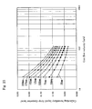
- Fig. 23 shows the relation between the flow velocity of the exhaust gas and the collecting boundary liquid drop diameter d min that has been obtained by the theory as mentioned above.
- Fig. 24(a) is a cross sectional view of the liquid drop eliminator 120 of Fig. 22 that is schematized for investigating the relation shown in Fig. 23 .
- the temperature of the exhaust gas is 30°C
- the viscosity ⁇ of the exhaust gas is 1.83 x 10 -5 kg/m/s
- lime water is used as the liquid
- the density ⁇ L of the liquid (liquid drop) is 1150 kg/m 3 .
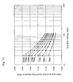
- Fig. 25 shows the relation between the flow velocity of the exhaust gas and the collecting boundary liquid drop diameter d min in the case where the same conditions as mentioned above are applied and water is used as the liquid.
- the density ⁇ L of the liquid (liquid drop) is 998 kg/m 3 .
- the flow velocity u of the exhaust gas is 5 m/s
- the temperature of the exhaust gas is 30°C
- the viscosity ⁇ of the exhaust gas is 1.83 x 10 -5 kg/m/s.
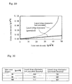
- Fig. 28 shows the relation between the liquid drop diameter and the collecting efficiency, obtained as the result of the above tests.
- the collecting efficiency ⁇ 1.0 is attained at the liquid drop diameter of approximately 3.00 x 10 -5 m (30 ⁇ m). If no liquid drop eliminator 120 is provided but only the mist eliminator 118 is provided, the mist eliminator 118 will collect all the liquid drops having the liquid drop diameter larger than this.
- the liquid drops having the liquid drop diameter of approximately 1.40 x 10 -4 to 1.50 x 10 -4 (140 to 150 ⁇ m) or more can be collected by the liquid drop eliminator 120 and the fine liquid drops having the liquid drop diameter of less than approximately 1.40 x 10 -4 to 1.50 x 10 -4 (140 to 150 ⁇ m) can be collected by the downstream mist eliminator 118.
- liquid drops can be collected by the liquid drop eliminator 120 and in this case also, the liquid can be prevented from passing through the mist eliminator as it is.
- Test object Two stages of eliminators, that is, the liquid drop eliminator 120 on the upstream side and the mist eliminator 118 on the downstream side, are provided.
- the liquid drop eliminator 120 is of the shape shown in Fig. 22 in which the interval P1 of the collecting plates 121 is 100 mm and the inclination angle ⁇ of the collecting plates 121 is 28°.
- the mist eliminator 118 is of the shape shown in Fig. 21 in which the interval P2 of the collecting plates 119 is 40 mm and the inclination angle ⁇ of the collecting plates 119 having three bent portions 119a is 45°.
- Fig. 29 shows the relation between the inlet side mist density and the outlet side mist density as the result of the tests.
- Fig. 30 shows comparison of the pressure loss between the Test Object and the Comparison Object and it is understood that, regardless of the inlet side mist density, the pressure loss can be suppressed by providing the liquid drop eliminator 120 having the larger pitch (the interval P1).
- the flow velocity of the exhaust gas to be used therefor may be the flow velocity of the exhaust gas of the usual operation time in the tower body 111 or may be set based on the maximum flow velocity of the exhaust gas in the tower body 111.
Landscapes
- Engineering & Computer Science (AREA)
- Chemical & Material Sciences (AREA)
- Environmental & Geological Engineering (AREA)
- Health & Medical Sciences (AREA)
- Biomedical Technology (AREA)
- Analytical Chemistry (AREA)
- General Chemical & Material Sciences (AREA)
- Oil, Petroleum & Natural Gas (AREA)
- Chemical Kinetics & Catalysis (AREA)
- Treating Waste Gases (AREA)
- Gas Separation By Absorption (AREA)
Description
- The present invention relates to an exhaust gas treating tower that is provided in various kinds of plants, boilers or the like.
- In order to remove sulfur oxides (SO2) contained in the exhaust gas of various kinds of plants, boilers or the like, an exhaust gas treating tower of gas-liquid contact type is often used.
- In the exhaust gas treating tower of this type, what is called a liquid column type is known in which absorbing liquid of the sulfur oxides is upwardly spouted in a column shape, as is known by the
Japanese laid-open utility model laid-open application 1984-53828 Fig. 1 ), for example. As shown inFigs. 31 and32 here, in such an exhaustgas treating tower 1 of liquid column type, the exhaust gas is introduced from aninlet port 2 formed in a lower side portion of the exhaustgas treating tower 1. While this exhaust gas is flowing up toward anoutlet port 3 formed in an upper portion of the tower, it makes contact with liquid columns C spouted in the column shape and thereby the sulfur oxides contained in the exhaust gas is removed. - In the exhaust gas treating tower of liquid column type so constructed, fine liquid drops (generally called a mist) are contained in the exhaust gas that has made contact with the liquid columns C to be discharged from the
outlet port 3 and in order to recover the mist, there is provided an eliminator 5 (Fig. 31 ) or a mist eliminator 6 (Fig. 32 ) at theoutlet port 3. - In the above-mentioned exhaust
gas treating tower 1 of liquid column type, in order to enhance the exhaust gas treating efficiency (treating quantity per unit time), it is necessary to make a large size plant or to increase the exhaust gas flow velocity. However, needless to mention, to make a large size plant is usually not preferable. Thus, to make the exhaust gas flow velocity higher than the present situation is considered. But in the conventional exhaustgas treating tower 1, as shown inFig. 9 , if the gas flow velocity is increased beyond a certain level, while the sulfur oxides cannot be sufficiently removed by the liquid columns C, the exhaust gas passes through the tower to be blown off outside as it is. Thus, there is a problem that the exhaust gas treating efficiency is hardly enhanced. - Also, in the example shown in
Fig. 32 , there will be caused a problem that while the liquid drops in the exhaust gas cannot be sufficiently recovered by themist eliminator 6, the liquid drops together with the exhaust gas pass through themist eliminator 6 to be discharged outside. - Here, as the exhaust gas flowing upward from below makes gas-liquid contact with the liquid columns C, the liquid drops generated in the vicinity of the liquid columns C receive an upward resisting force by the exhaust gas flow. According to the balance between the gravity force corresponding to the weight (diameter) of the liquid drops and the resisting force of the upwardly flowing exhaust gas (air resisting force), the liquid drops having a weight (diameter) beyond a certain level are entrained with the exhaust gas flow to move up toward the
mist eliminator 6 in the exhaustgas treating tower 1. - At this time, if the flow velocity of the exhaust gas becomes higher, the upper limit of the diameter of the liquid drops moving up in the exhaust
gas treating tower 1 becomes correspondingly larger and the quantity of the upwardly moving liquid drops also increases as a whole. Thus, the quantity of the liquid drops that must be collected in themist eliminator 6 increases and the quantity of the liquid sticking to surfaces of collectingplates 6a of themist eliminator 6 also increases. - On the other hand, while the flow velocity of the exhaust gas is high, the liquid sticking to the surfaces of the
collecting plates 6a is again scattered by the exhaust gas, resulting in that the liquid passes through themist eliminator 6. - When the exhaust
gas treating tower 1 is to be designed, a flow velocity of the exhaust gas at a steady operation time is set and, based on the so set exhaust gas flow velocity, the diameter of the liquid drops that move up in the exhaustgas treating tower 1 together with the exhaust gas is obtained and themist eliminator 6 is designed so that the liquid drops of the so obtained diameter can be securely collected. - Nevertheless, in the exhaust
gas treating tower 1, the exhaust gas flow is not always uniform but due to various causes, the flow often becomes unsteady and the flow velocity becomes also different according to the place. For this reason, actually, there often exists such an area where the exhaust gas flows at a velocity higher than the designed flow velocity of the steady operation time. In this area, the liquid drops of a diameter larger than a presumed diameter at the time of design move up toward themist eliminator 6 together with the exhaust gas and this likewise results in that the liquid is not sufficiently collected by themist eliminator 6 but passes therethough. -
US 4 157 250 discloses an exhaust gas treating tower according to the preamble ofclaim 1. - In view of the above-mentioned technical problems in the prior art, it is an object of the present invention to provide an exhaust gas treating tower by which the exhaust gas treating efficiency is enhanced by increasing the exhaust gas flow velocity more than the prior art case.
- Also, it is an object of the present invention to provide an exhaust gas treating tower by which liquid can be securely recovered.
- With the above objects in mind, the inventors here have carried out extensive studies and obtained the following observations.
- That is, in the exhaust
gas treating tower 1, there are provided a plurality ofnozzles 4 that spout the liquid to form the liquid columns C and the liquid spouted in the column shape from therespective nozzles 4 spreads sideward at the top position of the column shape and then flows down. Thus, between the liquid columns C spouted from the plurality ofnozzles 4, there are generated a rich area and a lean area of the liquid in the same one plane. As the exhaust gas flowing upward from below makes contact with the liquid columns C and the liquid drops in the surroundings of the liquid columns C so that the sulfur oxides are removed, the exhaust gas receives a resisting force by making contact with the liquid columns C and the liquid drops. If the flow velocity of the exhaust gas is increased, the resisting force given by the liquid columns C and the liquid drops becomes insufficient at the lean area of the liquid generated between the mutuallyadjacent nozzles - Thus, in the present invention, an exhaust gas treating tower is provided having the features recited in
claim 1. - In the exhaust gas treating tower constructed as mentioned above, the exhaust gas introduced from below of the tower body makes contact with the liquid columns in the first substance removing portion so that the substance contained in the exhaust gas is removed and further makes contact with the liquid in the second substance removing portion, that is provided in the area different from the liquid columns generated in the first substance removing portion, so that the substance contained in the exhaust gas is further removed.
- It will be most preferable if the exhaust gas treating tower is constructed such that an inlet port of the exhaust gas is provided in a side wall of the tower body below both of the first and second substance removing portions.
- Also, a nozzle that forms a liquid film by spouting the liquid in an umbrella shape may be provided as between the first and the second substance removing portions. This nozzle is preferably provided in a plural number and is preferably arranged such that the liquid films generated by the nozzles lap on the liquid films generated by adjacent ones of the nozzles so that no gap is formed therebetween.
- Also, the liquid to be spouted from the nozzles may be pressurized by a pump.
- These nozzles are preferably provided in a piping that supplies the liquid for generating the liquid columns in the first substance removing portion. Thereby, the piping can be commonly used both for the first and second substance removing portions and reduction of the opening rate in the tower body can be suppressed to the minimum.
- A collision member with which the liquid falling down from the liquid columns generated in the first substance removing portion or the liquid films generated by the nozzles collides so that liquid drops are generated is provided as the second substance removing portion. The collision member can generate the liquid drops, when the liquid falling down from the liquid films generated by the nozzles collides with the collision member. Also, the liquid drops can be generated, when the liquid falling down from the liquid columns generated in the first substance removing portion collides with the collision member.
- The tower may comprise a first liquid drop collecting portion provided on a downstream side of the liquid supply portion in a flow direction of the exhaust gas so as to collect the liquid drops contained in the exhaust gas that has made contact with the liquid, and a second liquid drop collecting portion provided on the downstream side of the liquid supply portion in the flow direction of the exhaust gas and on an upstream side of the first liquid drop collecting portion so as to collect the liquid drops larger than the liquid drops to be collected by the first liquid drop collecting portion out of the liquid drops contained in the exhaust gas.
- By providing the second liquid drop collecting portion on the upstream side of the first liquid drop collecting portion, in the upstream second liquid drop collecting portion, the liquid drops larger than the liquid drops to be collected by the first liquid drop collecting portion are collected. Thereby, in the downstream first liquid drop collecting portion, only the liquid drops smaller than the liquid drops collected by the second liquid drop collecting portion are collected.
- A concrete construction may be made such that the first liquid drop collecting portion comprises a plurality of first collecting plates arranged inclinedly relative to the flow direction of the exhaust gas with a predetermined pitch being maintained between each of the first collecting plates and the second liquid drop collecting portion comprises a plurality of second collecting plates arranged inclinedly relative to the flow direction of the exhaust gas with a predetermined pitch, larger than the pitch of the first collecting plates, being maintained between each of the second collecting plates.
- Here, the pitch of the second collecting plates may be set based on a flow velocity of the exhaust gas at a usual operation time in the tower body. For example, at the usual operation time in the tower body, supposing that the flow velocity of the exhaust gas is 5 m/ s, it is preferable that the inclination angle α of the second collecting plates is 28° and the pitch thereof is 100 to 150 mm. In this case, in the second collecting plates, the liquid drops having the particle diameter of approximately 3 mm or more can be collected. Also, in this case, it is preferable that the pitch of the first collecting plates is set to 40 to 60 mm.
- The pitch of the second collecting plates may also be set based on a maximum flow velocity of the exhaust gas in the tower body. Thereby, even if the flow of the exhaust gas in the tower body is in an unsteady state, the liquid drops can be sufficiently collected.
- According to the present invention, the gas-liquid contact efficiency is enhanced and the exhaust gas treating efficiency can be enhanced. Thus, by increasing the flow velocity of the exhaust gas more than in the prior art case, the performance of the exhaust gas treating tower can be enhanced. Or if the equivalent performance is to be maintained, the exhaust gas treating tower can be made compact to that extent.
- Also, according to the present invention, by providing the liquid drop eliminator, the flow velocity of the exhaust gas can be increased or even if there is caused an area where the exhaust gas flow velocity becomes higher than presumed, the liquid can be securely recovered.
-
-
Fig. 1 is a cross sectional view showing a construction of an exhaust gas treating tower of a first embodiment according to the present invention. -
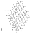
Fig. 2 is a perspective view of a liquid drop generating member. -
Fig. 3 is a cross sectional view showing a liquid drop generating state in the liquid drop generating member ofFig. 2 . -
Fig. 4 is a cross sectional view showing a modification example of the exhaust gas treating tower of the first embodiment ofFig. 1 . -
Fig. 5 is a cross sectional view showing a construction of an exhaust gas treating tower of a second embodiment which is not according to the invention. -
Fig. 6 is a cross sectional view showing a modification example of the exhaust gas treating tower of the second embodiment ofFig. 5 . -
Fig. 7 is a cross sectional view showing a construction of an exhaust gas treating tower of a third embodiment. -
Fig. 8 is a cross sectional view showing a modification example of the exhaust gas treating tower of the third embodiment ofFig. 7 . -
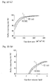
Fig. 9 is an explanatory view showing the relation between a gas flow velocity and a density of sulfur oxides at a tower outlet as the result of performance evaluation tests of the exhaust gas treating towers of the first to the third embodiments as well as of a prior art exhaust gas treating tower for comparison purpose. -
Fig. 10 is an explanatory view showing the relation between a liquid unit flow rate and the gas flow velocity as the result of the same tests ofFig. 9 . -
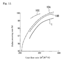
Fig. 11 is an explanatory view showing the relation between the liquid unit flow rate and a sulfur removing rate as the result of the same tests ofFig. 9 . -
Fig. 12 is a cross sectional view showing a construction of an exhaust gas treating tower of a fourth embodiment which is not according to the invention. -
Fig. 13 is an explanatory view showing an installation example of the spray nozzles and comprisesFigs. 13(a) and 13(b) , whereinFig. 13(a) is a front view andFig. 13(b) is a cross sectional view seen in the direction of arrows ofFig. 13(a) . -
Fig. 14 is an explanatory view showing another installation example of the spray nozzles ofFig. 13 and comprisesFigs. 14(a) and 14(b) , whereinFig. 14(a) is a front view andFig. 14(b) is a cross sectional view seen in the direction of arrows ofFig. 14(a) . -
Fig. 15 is an explanatory view showing still another installation example of the spray nozzles ofFig. 13 and comprisesFigs. 15(a) and 15(b) , whereinFig. 15(a) is a front view andFig. 15(b) is a cross sectional view seen in the direction of arrows ofFig. 15(a) . -
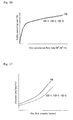
Fig. 16 is an explanatory view showing the relation between a unit circulation flow rate and the sulfur removing rate as the result of tests for a performance comparison between the exhaust gas treating towers of the second embodiment ofFig. 5 and the fourth embodiment ofFig. 12 . -
Fig. 17 is an explanatory view showing the relation between the gas flow velocity and a pressure loss as the result of the same tests ofFig. 16 . -
Fig. 18 is a cross sectional view showing a modification example of an exhaust gas treating tower not according to the invention in which an inclined surface portion is provided in the vicinity of an inlet port of the exhaust gas treating tower. -
Fig. 19 is a cross sectional view showing another modification example of an exhaust gas treating tower not according to the invention in which rectifying plates are provided in the exhaust gas treating tower. -
Fig. 20 is an explanatory view showing the result of a performance test of the case where the inclined surface portion ofFig. 18 and the rectifying plates ofFig. 19 are provided and comprisesFigs. 20(a) and 20(b) , whereinFig. 20(a) shows the relation between the liquid unit flow rate and the sulfur removing rate andFig. 20(b) shows the relation between the gas flow velocity and the sulfur removing rate. -
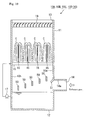
Fig. 21 is a cross sectional view showing a construction of an exhaust gas treating tower of a fifth embodiment not according to the invention. -
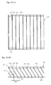
Fig. 22 is an explanatory view showing a construction of a liquid drop eliminator used in the fifth embodiment ofFig. 21 and comprisesFigs. 22(a) and 22(b) , whereinFig. 22(a) is a plan view andFig. 22(b) is a cross sectional elevation view. -
Fig. 23 is an explanatory view showing the relation between the exhaust gas flow velocity and a collecting boundary liquid drop diameter as the result of tests in which lime water is used as the liquid and intervals between each of collecting plates having the shape ofFig. 24(a) are variously changed. -
Fig. 24 shows a cross sectional shape of collecting plates used for obtaining the relation between the exhaust gas flow velocity and the collecting boundary liquid drop diameter and comprisesFigs. 24(a) and 24(b) , whereinFig. 24(a) shows an inclined flat plate shape andFig. 24(b) shows an inequality mark shape having one bent portion. -
Fig. 25 is an explanatory view showing the relation between the exhaust gas flow velocity and the collecting boundary liquid drop diameter as the result of the same tests ofFig. 23 in which water is used as the liquid and intervals between each of the collecting plates having the shape ofFig. 24(a) are variously changed. -
Fig. 26 is an explanatory view showing the relation between the exhaust gas flow velocity and the collecting boundary liquid drop diameter as the result of tests in which lime water is used as the liquid and intervals between each of collecting plates having the shape ofFig. 24(b) are variously changed. -
Fig. 27 is an explanatory view showing the relation between the exhaust gas flow velocity and the collecting boundary liquid drop diameter as the result of the same tests ofFig. 26 in which water is used as the liquid and intervals between each of collecting plates having the shape ofFig. 24(b) are variously changed. -
Fig. 28 is an explanatory view showing the relation between a liquid drop diameter and a collecting efficiency with respect to both of a mist eliminator and the liquid drop eliminator used in the fifth embodiment ofFig. 22 . -
Fig. 29 is an explanatory view showing the relation between an inlet mist density and an outlet mist density as the result of tests using the fifth embodiment ofFig. 22 . -
Fig. 30 is an explanatory view showing a pressure loss as the result of the tests ofFig. 29 . -
Fig. 31 is a cross sectional view showing a construction of a prior art exhaust gas treating tower. -
Fig. 32 is a cross sectional view showing a construction of another prior art exhaust gas treating tower. - Herebelow, the present invention will be described more concretely based on embodiments according to the present invention with reference to the appended drawings.
-
Fig. 1 is an explanatory cross sectional view of a construction of an exhaustgas treating tower 10A of a first embodiment. As shown inFig. 1 , the exhaustgas treating tower 10A comprises atower body 11 formed, for example, in a duct shape having a rectangular cross sectional shape and has its bottom portion closed by abottom plate 12 and its upper portion formed with an openingportion 13. Also, in a lower side wall of thetower body 11, aninlet port 14 opens through which exhaust gas is introduced into thetower body 11. - There is provided in the tower body 11 a
piping 16 comprising a plurality ofnozzles 15. The piping 16 is supplied with liquid, stored in the bottom portion of thetower body 11, pumped up by apump 17. This liquid is spouted upward from thenozzles 15 to form liquid columns C of a column shape. The plurality ofnozzles 15 are arranged with an appropriately set interval between them so that no gap is generated between the liquid columns C spouted from the mutuallyadjacent nozzles 15. - In the present embodiment, there is provided a liquid
drop generating member 20 at a position below thenozzles 15 and above theinlet port 14 in thetower body 11. - As shown in
Figs. 2 and3 , the liquiddrop generating member 20, often called a grid etc., is formed in a grid shape as a whole in which longitudinal plate portions (collision members) 21 and lateral plate portions (collision members) 22 are assembled together so as to orthogonally cross each other with predetermined intervals between them. Thelongitudinal plate portions 21 and thelateral plate portions 22 have their respectiveupper surfaces longitudinal plate portions 21 and thelateral plate portions 22, respectively, have a predetermined height, so that, in the portions surrounded by the mutually adjacentlongitudinal plate portions lateral plate portions - In the exhaust
gas treating tower 10A constructed as mentioned above, the liquid spouted upward from thenozzles 15 forms the liquid columns C and falls down. The liquid so falling down collides with theupper surfaces drop generating member 20 to become fine liquid drops M. - While the liquid drops M so generated usually fall down as they are in a floating state, in the present embodiment, there are formed the spaces S in the liquid
drop generating member 20. Hence, by friction force with the wall surfaces of thelongitudinal plate portions 21 and thelateral plate portions 22, the liquid drops M are retained in the floating state longer than usual in the spaces S. It is to be noted, as easily understood, that this phenomenon is the same as that a fluid flow velocity becomes smaller by friction with a wall surface as the fluid approaches nearer to the vicinity of the wall surface along the flow. - Then, the liquid drops M further fall down in the exhaust
gas treating tower 10A to be stored in the bottom portion. - On the other hand, the exhaust gas introduced substantially horizontally from the
inlet port 14 turns in the exhaustgas treating tower 10A to flow upward. Then, the exhaust gas makes contact with the liquid columns C spouted upward from thenozzles 15, as a first substance removing portion, so that sulfur oxides in the exhaust gas are absorbed into the liquid and the exhaust gas is discharged outside from the opening portion of the upper position. Also, in the liquiddrop generating member 20 as a second substance removing portion, the fine liquid drops M are generated by the liquid colliding with theupper surfaces - It is to be noted that, as shown in
Fig. 1 , there is provided aneliminator 18 at an upper position of the exhaustgas treating tower 10A and the fine liquid drops M remaining in the exhaust gas are removed to be recovered by theeliminator 18. - As mentioned above, by the exhaust
gas treating tower 10A being provided with the liquiddrop generating member 20, not only the liquid columns C are formed but also the liquid drops M of the floating state can be generated in the vicinity of the liquiddrop generating member 20. Thereby, the liquid drops M are caused to exist in the area of the exhaustgas treating tower 10A where there has been no gas absorbing liquid in the prior art case and this results in enhancing the removing performance of the sulfur oxides. - Also, as the exhaust gas receives resisting force by making contact with the liquid columns C and the liquid drops M, as compared with the case of only the liquid columns C in the prior art, the resisting force can be increased as a whole by the existence of the liquid drops M and thereby the gas-liquid contact efficiency can be enhanced. Thus, even if the flow velocity of the exhaust gas is increased more than the conventional case, the boundary flow velocity by which the exhaust gas is blown off as it is can be enhanced and the sulfur removing performance of the exhaust
gas treating tower 10A can be remarkably enhanced. Also, if the same or equivalent performance is to be obtained, the exhaustgas treating tower 10A can be made smaller than the conventional case to the extent that the flow rate of the exhaust gas is increased. - In the present embodiment, while the liquid
drop generating member 20 is arranged below thenozzles 15, as shown inFig. 4 , such a construction can be employed as to arrange the liquiddrop generating member 20 above the liquid columns C generated by thenozzles 15. Also, it is a matter of course that the liquiddrop generating members 20 can be arranged both above and below thenozzles 15. - In case the liquid
drop generating member 20 is arranged above the liquid columns C, the liquid drops M generated at the liquid columns C and entrained with the exhaust gas flowing upward are retained in the spaces S of the liquiddrop generating member 20. Hence, the sulfur oxides removing effect of the exhaust gas and the resisting force giving effect against the flow of the exhaust gas can be obtained. - Next, an example in which an exhaust
gas treating tower 10B is additionally provided withspray nozzles 30 will be described. It is to be noted that, as the basic construction of the exhaustgas treating tower 10B is the same as the above-mentioned first embodiment, designation by the same reference numerals is employed and description thereof will be omitted. - As shown in
Fig. 5 , the exhaustgas treating tower 10B comprises a piping 31 provided with the plurality ofspray nozzles 30 at a position below thenozzles 15 and above theinlet port 14 in thetower body 11. - A
pressure elevating pump 33 is connected to the piping 31 so that pressure of the liquid pumped up by thepump 17 from the bottom portion of thetower body 11 is further elevated. It is to be noted that, without providing thepump 17 and thepressure elevating pump 33 in two stages, such a construction can be employed as to pump the liquid up from the bottom portion of thetower body 11 only by thepressure elevating pump 33. In this case, thepressure elevating pump 33 preferably elevates the pressure of the liquid higher than the pressure of thepump 17. Also, such a construction as to have nopressure elevating pump 33 but to have only thepump 17 is possible. - The liquid of which pressure has been elevated by the
pressure elevating pump 33 is spouted from each of thespray nozzles 30 in an umbrella shape (conical shape) having its entire outer circumferential periphery formed by a continuous liquid film F. The plurality ofspray nozzles 30 are arranged so that the liquid films F spouted in the umbrella shape from the mutuallyadjacent spray nozzles 30 lap one on another and no gap between the liquid films F is formed in thetower body 11. - In the exhaust
gas treating tower 10B constructed as mentioned above, the exhaust gas introduced substantially horizontally from theinlet port 14 turns in the exhaustgas treating tower 10B to flow upward. Then, the exhaust gas makes contact with the liquid columns C spouted upward from thenozzles 15, as the first substance removing portion, so that the sulfur oxides in the exhaust gas is absorbed into the liquid and the exhaust gas is discharged from the openingportion 13 of the upper position. Also, the exhaust gas makes contact with the liquid films F spouted in the umbrella shape from thespray nozzles 30, as the second substance removing portion, and thereby also the sulfur oxides in the exhaust gas can be absorbed. - As mentioned above, by the exhaust
gas treating tower 10B being provided with thespray nozzles 30, the liquid films F are caused to exist in the area, different from the liquid columns C, of the exhaustgas treating tower 10B where there has been no gas absorbing liquid in the prior art case and this results in enhancing the removing performance of the sulfur oxides. - At this time, the
spray nozzles 30 are arranged so that the liquid films F spouted in the umbrella shape from the mutuallyadjacent spray nozzles 30 lap one on another and no gap between the liquid films F is formed in thetower body 11. Thereby, the liquid is caused to exist even in the portion where the existence of the liquid by forming the liquid columns C is lean. Also, the removing performance of the sulfur oxides in the exhaustgas treating tower 10B can be made uniform and also an effect to rectify the flow of the gas can be obtained. - Also, as the exhaust gas receives resisting force by making contact with the liquid columns C and the liquid films F, as compared with the case of only the liquid columns C in the prior art, the resisting force can be increased as a whole by the existence of the liquid films F and thereby the gas-liquid contact efficiency can be enhanced. Thus, even if the flow velocity of the exhaust gas is increased more than the conventional case, the boundary flow velocity by which the exhaust gas is blown off as it is can be enhanced and the sulfur removing performance of the exhaust
gas treating tower 10B can be remarkably enhanced. Also, if the same or equivalent performance is to be obtained, the exhaustgas treating tower 10B can be made smaller than the conventional case to the extent that the flow rate of the exhaust gas is increased. - By the way, in the present embodiment, in addition to the liquid columns C, the liquid films F are formed by the
spray nozzles 30 that spout the liquid of which pressure has been elevated by thepressure elevating pump 33. While such a construction is considered as to use no liquid column C but to provide thespray nozzles 30 in plural stages so that the removal of the sulfur oxides is done only by the liquid films F of the plural stages, in this case, pressure of all the liquid to be spouted must be elevated by thepressure elevating pump 33. On the contrary, in the present embodiment described above, by spouting the liquid films F from thespray nozzles 30, pressure of only the liquid to be supplied to thespray nozzles 30 can be elevated by thepressure elevating pump 33. - In the present embodiment, while the
spray nozzles 30 are arranged below thenozzles 15, as shown inFig. 6 , such a construction can be employed as to arrange thespray nozzles 30 above the liquid columns C generated by thenozzles 15. Also, it is a matter of course that thespray nozzles 30 can be arranged both above and below thenozzles 15. - Next, an example in which an exhaust
gas treating tower 10C is additionally provided with a combination of the liquiddrop generating member 20 and thespray nozzles 30 will be described. It is to be noted that, as the basic construction of the exhaustgas treating tower 10C is the same as the above-mentioned first and second embodiments, designation by the same reference numerals is employed and description thereof will be omitted. - As shown in
Fig. 7 , the exhaustgas treating tower 10C comprises the piping 31 provided with the plurality ofspray nozzles 30 at a position below thenozzles 15 and above theinlet port 14 in thetower body 11. Further, the exhaustgas treating tower 10C comprises the liquiddrop generating member 20 at a position below thespray nozzles 30 and above theinlet port 14. - In the exhaust
gas treating tower 10C constructed as mentioned above, the liquid spouted upward from thenozzles 15 forms the liquid columns C and falls down. The liquid so falling down collides with theupper surfaces drop generating member 20 to become the fine liquid drops M. - Also, the liquid of which pressure has been elevated by the
pressure elevating pump 33 is spouted from each of thespray nozzles 30 in the umbrella shape (conical shape) to form the liquid film F. The liquid that has formed the liquid films F further falls down and collides with theupper surfaces drop generating member 20 to become the fine liquid drops M. - The liquid drops M so generated are retained in the floating state in the plurality of spaces S formed in the liquid
drop generating member 20. - Then, the liquid drops M further fall down in the exhaust
gas treating tower 10C to be stored in the bottom portion. - In the above-mentioned exhaust
gas treating tower 10C, the exhaust gas introduced substantially horizontally from theinlet port 14 turns in the exhaust gas treating tower C to flow upward. Then, the exhaust gas makes contact with the fine liquid drops M retained in the floating state in the spaces S of the liquiddrop generating member 20 as the second substance removing portion and also makes contact with the liquid films F spouted in the umbrella shape from thespray nozzles 30 likewise as the second substance removing portion as well as with the liquid columns C spouted upward from thenozzles 15 as the first substance removing portion. Thereby, the sulfur oxides in the exhaust gas are absorbed into the liquid and then the exhaust gas is discharged outside from the openingportion 13 of the upper position. - As mentioned above, by the exhaust
gas treating tower 10C being provided with the liquiddrop generating member 20 and thespray nozzles 30, the liquid drops M and the liquid films F are caused to exist in the area of the exhaustgas treating tower 10C where there has been no gas absorbing liquid in the prior art case and this results in enhancing the removing performance of the sulfur oxides. - Also, as the exhaust gas receives resisting force by making contact with the liquid columns C, the liquid films F and the liquid drops M, as compared with the case of only the liquid columns C in the prior art, the resisting force can be increased as a whole by the existence of the liquid films F and the liquid drops M and thereby the gas-liquid contact efficiency can be enhanced. Thus, even if the flow velocity of the exhaust gas is increased more than the conventional case, the boundary flow velocity by which the exhaust gas is blown off as it is can be enhanced and the sulfur removing performance of the exhaust
gas treating tower 10C can be remarkably enhanced. Also, if the same or equivalent performance is to be obtained, the exhaustgas treating tower 10C can be made smaller than the conventional case to the extent that the flow rate of the exhaust gas is increased. - By the way, in the present embodiment comprising both of the liquid
drop generating member 20 and thespray nozzles 30, as compared with the first embodiment comprising only the liquiddrop generating member 20 and the second embodiment comprising only thespray nozzles 30, the liquid of the liquid films F formed by thespray nozzles 30 collides with theupper surfaces drop generating member 20 to become the liquid drops M. Hence, the quantity of generation of the liquid drops M becomes more than that of a case of simple combination. Therefore, the above-mentioned effect of the exhaustgas treating tower 10C of the present embodiment becomes further remarkable. - In the present embodiment, while the liquid
drop generating member 20 and thespray nozzles 30 are arranged below thenozzles 15, as shown inFig. 8 , such a construction can be employed as to also arrange the same ones above the liquid columns C formed by thenozzles 15. Also, it is a matter of course that none of the liquiddrop generating member 20 and thespray nozzles 30 is arranged below thenozzles 15 but they can be arranged only above the liquid columns C. - Here, various tests to evaluate the performance of the exhaust
gas treating towers - The exhaust
gas treating tower 10A of the first embodiment shown inFig. 1 , the exhaustgas treating tower 10B of the second embodiment shown inFig. 5 and the exhaustgas treating tower 10C of the third embodiment shown inFig. 7 as well as the prior art exhaustgas treating tower 1, for comparison purpose, shown inFig. 31 are used for the tests. Where the SO2 density at the tower inlet (inlet port 14) is 2700 ppm D and the liquid for the sulfur removal is of NH3 concentration of 270 m mol/l and calcium carbonate concentration of 115 m mol/l, the relation between the gas velocity and the SO2 density at the outlet (opening portion 13) of the exhaustgas treating tower 10 is investigated. At this time, in the prior art exhaustgas treating tower 1 and the exhaustgas treating tower 10A of the first embodiment comprising only the liquiddrop generating member 20, the circulation flow rate of the liquid is 304 m3/(m2 x h). In the exhaustgas treating tower 10B of the second embodiment comprising only thespray nozzles 30 and the exhaustgas treating tower 10C of the third embodiment comprising both of the liquiddrop generating member 20 and thespray nozzles 30, the circulation flow rate of the liquid for generating the liquid columns C is 274 m3/(m2 x h) and the flow rate of the liquid supplied into thespray nozzles 30 is 59 m3/(m2 x h). - As the result thereof, as shown in
Fig. 9 , as compared with the prior art exhaustgas treating tower 1, in the exhaustgas treating towers gas treating tower 10C of the third embodiment comprising both of the liquiddrop generating member 20 and thespray nozzles 30, as compared with the exhaustgas treating tower 10A of the first embodiment comprising only the liquiddrop generating member 20 and the exhaustgas treating tower 10B of the second embodiment comprising only thespray nozzles 30, the boundary flow velocity is high. - Also, the relation between a flow rate of a downflow liquid per unit cross sectional area (this is called a unit flow rate) of the liquid column C and the gas flow velocity (boundary flow velocity) is investigated.
- As the result thereof, as shown in
Fig. 10 , it is understood that, if the unit flow rate of the liquid is of the same conditions, as compared with the prior art exhaustgas treating tower 1, in the exhaustgas treating towers - Further, the relation between the unit flow rate of the liquid column C and the sulfur removing rate is investigated.
- As the result thereof, as shown in
Fig. 11 , if the unit flow rate of the liquid is of the same conditions, as compared with the prior art exhaustgas treating tower 1, in the exhaustgas treating towers gas treating tower 10B) to 30% (in the case of the exhaustgas treating towers gas treating tower 1, the sulfur removing performance is enhanced by 1.1 to 1.3 times. - Next, an example in which, like in the above-mentioned second embodiment, an exhaust
gas treating tower 10D is additionally provided withspray nozzles 30 will be described. It is to be noted that, as the basic construction of the exhaustgas treating tower 10D is the same as the above-mentioned first embodiment, designation by the same reference numerals is employed and description thereof will be omitted. - As shown in
Fig. 12 , the exhaustgas treating tower 10D comprises the plurality ofspray nozzles 30 at a position below thenozzles 15 and above theinlet port 14 in thetower body 11. - Here, as the difference in the construction from the exhaust
gas treating tower 10B of the above-mentioned second embodiment in which thespray nozzles 30 are provided in the piping 31 that is separate from the piping 16 in which thenozzles 15 are provided, in the exhaustgas treating tower 10D of the present embodiment, thespray nozzles 30 are provided in the piping 16 in which thenozzles 15 are provided. - In
Figs. 13 to 15 , examples of detailed structures by which thespray nozzles 30 are fitted to the piping 16 are shown, wherein each ofFigs. 13 to 15 comprises (a) as a front view and (b) as a cross sectional view at the position of arrows of (a). - In the exhaust
gas treating tower 10D-1 ofFig. 13 , the piping 16 is provided withflange members 40, projecting upward, to which thenozzles 15 are fitted. Also, the piping 16 is provided withflange members 41 projecting substantially horizontally. Theflange members 41 are fitted with thespray nozzles 30 that downwardly spout the liquid in the umbrella shape so as to form the liquid films F. Here, each of theflange members 41 can be appropriately arranged so that, for example, oneflange member 41 corresponds to two or threenozzles 15. - In case the
spray nozzles 30 are provided to be added to an existing exhaust gas treating tower so that the exhaustgas treating tower 10D-1 is realized, theflange members 41 are fitted to thepiping 16 and thespray nozzles 30 are fitted to theflange members 41. - In the exhaust
gas treating tower 10D-2 ofFig. 14 , the piping 16 is provided with theflange members 40, projecting upward, to which thenozzles 15 are fitted and also is provided withflange members 42 likewise projecting upward. Theflange members 42 are fitted withextension pipes 43 that have their distal end portions fitted with thespray nozzles 30. Theextension pipes 43 are formed in a bent shape and arranged so as to maintain an attitude and position of thespray nozzles 30 such that the liquid is spouted downward from thespray nozzles 30 and yet the spouted liquid does not interfere with thepiping 16. Here, each of theflange members 42 can be arranged, for example, at a mid position between the mutually adjacent twonozzles 15 of a pair so that oneflange member 42 corresponds to twonozzles 15. - In case the
spray nozzles 30 are provided to be added to an existing exhaust gas treating tower so that the exhaustgas treating tower 10D-2 is realized, theflange members 42 are fitted to thepiping 16 and theextension pipes 43 and thespray nozzles 30 are fitted to theflange members 42. - In the exhaust
gas treating tower 10D-3 ofFig. 15 , the piping 16 is provided with theflange members 40, projecting upward, to which thenozzles 15 are fitted and theflange members 40 are provided with thespray nozzles 30 via take-offpipes 45. - Each of the take-off
pipes 45 has an equivalent inner diameter to theflange member 40 and comprises amain body portion 45a having its upper and lower ends fitted with flanges so as to be interposed between theflange member 40 and thenozzle 15 and a bifurcatingportion 45b that bifurcates sideward from themain body portion 45a and has its distal end fitted with thespray nozzle 30. The bifurcatingportion 45b is formed in a bent shape and arranged so as to maintain an attitude and position of thespray nozzle 30 such that the liquid is spouted downward from thespray nozzle 30 and yet the spouted liquid does not interfere with thepiping 16. Here, the take-offpipe 45 can be arranged so that, for example, one take-offpipe 45 corresponds to twonozzles 15. - In case the
spray nozzles 30 are provided to be added to an existing exhaust gas treating tower so that the exhaustgas treating tower 10D-3 is realized, the existingnozzles 15 are detached from theflange members 40 and then the take-offpipes 45 are attached and thenozzles 15 are again fitted to these take-offpipes 45 and thespray nozzles 30 are fitted to the distal end portions of the take-offpipes 45. - In the constructions shown in
Figs. 12 to 15 , the liquid of which pressure is elevated by thepump 17 passes through the piping 16 and is spouted from thenozzles 15 and thespray nozzles 30 to thereby form the liquid columns C and the liquid films F. Thus, like in the exhaustgas treating tower 10B of the above-mentioned second embodiment, by the exhaustgas treating towers 10D (10D-1, 10D-2, 10D-3) being provided with thespray nozzles 30, enhancement of the removing performance of the sulfur oxides, enhancement of the sulfur removing performance, etc. become possible. - In the exhaust
gas treating towers drop generating member 20 and/or the piping 31 to which thespray nozzles 30 are fitted and, to this extent, the opening rate of the gas path in the exhaustgas treating towers - Contrary to this, in the exhaust
gas treating tower 10D of the present embodiment, thespray nozzles 30 are provided in the piping 16 in which thenozzles 15 for generating the liquid columns C are provided. Hence, the reduction of the opening rate is suppressed and the pressure loss can be made smaller. - Here, various tests have been done for comparison between the exhaust
gas treating towers 10D (10D-1, 10D-2, 10D-3) of the present embodiment and the exhaustgas treating tower 10B of the second embodiment shown inFig. 5 and the results are shown below: - In the exhaust
gas treating tower 10B as well as in the exhaustgas treating towers 10D-1, 10D-2 and 10D-3, respectively, the temperature in the tower is 30°C, the flow velocity of the gas is 2.5 to 4.5 m/s, the SO2 density at the tower inlet (inlet port 14) is 500 ppm D, the liquid for the sulfur removal is of calcium carbonate concentration of 160 m mol/l, the height of spouting of the liquid columns C from thenozzles 15 is 1 to 5 m and the circulation flow rate of the liquid is 150 to 600 m3/(m2 x h). - In the above-mentioned state, the relation between the unit circulation flow rate and the sulfur removing rate and the relation of the pressure loss to the flow velocity of the gas are investigated.
-
Figs. 16 and 17 show the results of the tests. - As shown in
Fig. 16 , between the exhaustgas treating towers 10D-1, 10D-2 and 10D-3 of the present embodiment and the exhaustgas treating tower 10B of the second embodiment shown inFig. 5 , it is understood that approximately the same sulfur removing performance is obtained. Also, as shown inFig. 17 , between the exhaustgas treating towers 10D-1, 10D-2 and 10D-3 of the present embodiment and the exhaustgas treating tower 10B of the second embodiment shown inFig. 5 , it is understood that the pressure loss is more largely reduced in the exhaustgas treating towers 10D-1, 10D-2 and 10D-3 of the present embodiment. That is, in the exhaustgas treating towers 10D-1, 10D-2 and 10D-3 of the present embodiment, as compared with the exhaustgas treating tower 10B of the second embodiment, while the sulfur removing rate is maintained, the pressure loss can be largely reduced. - By the way, at the portions on which the liquid does not directly hit in the exhaust gas treating tower, scales are liable to stick due to the SO2 component in the liquid. For example, in the exhaust
gas treating towers drop generating member 20 and/or the piping 31 to which thespray nozzles 30 are fitted. Hence, as compared with the exhaustgas treating tower 10D (10D-1, 10D-2, 10D-3), the surface area of the portions on which the liquid does not directly hit is large and the scales easily stick there. If the sticking scales drop, there is a possibility that the below positioned nozzles, pipings or the like may be damaged. In the exhaustgas treating towers 10D (10D-1, 10D-2, 10D-3) of the present embodiment, thespray nozzles 30 are provided in thepiping 16 and thereby the portions to which the scales may stick can be made minimum and occurrence of the damage can also be suppressed. - Also, in case the
spray nozzles 30 are provided to be added to an existing exhaust gas treating tower so that the exhaustgas treating towers 10D-1, 10D-2 and 10D-3 are realized, theflange members 41, theextension pipes 43 and the take-offpipes 45 are fitted to the existingpiping 16 and then thenozzles 15 can be fitted to them. Also, thespray nozzles 30 can be fitted to the distal end portions of the take-offpipes 45. As compared with the exhaustgas treating towers drop generating member 20 and/or the piping 31 must be provided and a large scale of installation work is required therefor, an exhaust gas treating tower having less number of parts and less manufacturing cost can be realized with an easy work of installation. - Especially, in case of the exhaust
gas treating tower 10D-3 shown inFig. 15 , only by fitting the take-offpipes 45 to the existingflange members 40 to which thenozzles 15 are fitted, the exhaustgas treating tower 10D-3 can be realized. Thus, as compared with the exhaustgas treating towers 10D-1 and 10D-2 in which welding or the like is required for fitting theflange members 41 and theextension pipes 43, the same effect as mentioned above can be obtained with easy work and less cost. - Also, in the exhaust
gas treating tower 10D-2 shown inFig. 14 , it is likewise possible to fit theextension pipes 43 and thespray nozzles 30 to the existingflange members 40 to which thenozzles 15 are fitted, but this will not be preferable, because, in that case, the number of thenozzles 15 for forming the liquid columns C will be reduced. - It is to be noted that, in the present fourth embodiment mentioned above, while the example has been described in which the place and number of installations of the
flange members 41 and theextension pipes 43 of the exhaustgas treating towers 10D-1 and 10D-2 are decided by the relation with the installation positions of thenozzles 15, the invention is not limited thereto. Especially, in case an existing exhaust gas treating tower is not modified but the exhaustgas treating towers 10D-1 and 10D-2 are newly installed, theflange members 41 and theextension pipes 43 may be provided at such positions and in such number that the arrangement of thespray nozzles 30 can be optimized. - By the way, in the exhaust
gas treating towers gas treating tower 10, unless a discrimination is specifically needed.), it is effective if constructions mentioned below are combined therewith: - As shown in
Fig. 18 , in the portion of theinlet port 14 of the exhaustgas treating tower 10 not according to the invention, between a perpendicularinner wall surface 10a of the exhaustgas treating tower 10 and an upperinner surface 14a of theinlet port 14, aninclined surface portion 48 having an inclination of a predetermined angle is formed. By thisinclined surface portion 48, the cross sectional area of theinlet port 14 is gradually enlarged toward upward as it approaches nearer to the perpendicularinner wall surface 10a of the exhaustgas treating tower 10. - By forming such
inclined surface portion 48, at the portion where the flow of the exhaust gas introduced from theinlet port 14 turns upward, the flow velocity on the inner wall surface side can be increased and thereby a bias flow in thetower body 11 of the exhaustgas treating tower 10 can be suppressed. - By combining the
inclined surface portion 48 with each of the above-mentioned embodiments, the flow of the exhaust gas can be made uniform and the above-mentioned effects can be made more remarkable. - In
Fig. 19 , in front of theinlet port 14 in thetower body 11 of the exhaustgas treating tower 10 not according to the invention, a plurality of rectifyingplates 50 are provided along the direction approximately orthogonal to the flow direction of the exhaust gas supplied from theinlet port 14. The rectifyingplates 50 are arranged such that the rectifyingplates 50 that exist nearer to theinlet port 14 are provided at higher positions so that their heights are different from each other. Also, aflap 51 is provided projecting inclinedly from the crossing portion of the upperinner surface portion 14a of theinlet port 14 and the perpendicular innerwall surface portion 10a. - By the rectifying
plates 50 and theflap 51 constructed as mentioned above, at the portion where the exhaust gas introduced from theinlet port 14 turns upward, the exhaust gas is led to the rectifyingplates 50 by theflap 51 and hit on each of the rectifyingplates 50 to thereby be turned upward. If there are nosuch rectifying plates 50, the higher is the flow velocity of the exhaust gas, the more proceeds the exhaust gas straight toward the perpendicularinner wall surface 10b in front of theinlet port 14 and the more becomes the component that hits on the perpendicularinner wall surface 10b to thereby be directed upward. On the contrary, by the flow of the exhaust gas hitting on each of the rectifyingplates 50 to thereby be turned, as mentioned above, the bias flow in thetower body 11 of the exhaustgas treating tower 10 can be suppressed. By combiningsuch rectifying plates 50 with each of the mentioned embodiments, the flow of the exhaust gas can also be made uniform and the above-mentioned effects can be made further remarkable. - Here, various tests for verifying the effect of providing the above-mentioned
inclined surface portion 48 and the rectifyingplates 50 have been carried out and the results thereof are shown below: - In the exhaust
gas treating tower 10 provided with theinclined surface portion 48 as shown inFig. 18 and the exhaustgas treating tower 10 provided with the rectifyingplates 50 shown inFig. 19 as well as in the prior art exhaustgas treating tower 1 shown inFig. 31 , the tests have been done on the same conditions as mentioned above and the relation between the unit flow rate of the liquid and the sulfur removing rate [seeFig. 20(a) ] and the relation between the gas flow velocity and the sulfur removing rate [seeFig. 20(b) ] are investigated. - As the results thereof, as shown in
Figs. 20(a) and 20(b) , if the unit flow rate of the liquid and the gas flow velocity are of the same conditions, as compared with the prior art exhaustgas treating tower 1, it is understood that the sulfur removing rate is enhanced in the exhaustgas treating towers 10 provided with theinclined surface portion 48 or the rectifyingplates 50. - Thus, by providing the
inclined surface portion 48 or the rectifyingplates 50, the performance of the exhaustgas treating towers -
Fig. 21 is an explanatory view of an exhaustgas treating tower 100 of a fifth embodiment which is not according to the invention. - As shown in
Fig. 21 , the exhaustgas treating tower 100 comprises atower body 111 formed in a duct shape having, for example, a rectangular cross sectional shape and has its bottom portion closed by abottom plate 112 and its upper portion formed with anopening portion 113. Also, in a lower side surface of thetower body 111, aninlet port 114 opens through which the exhaust gas is introduced into thetower body 111. - There is provided in the tower body 111a piping 116 comprising a plurality of
nozzles 115. The piping 116 is supplied with the liquid, stored in the bottom portion of thetower body 111, pumped up by apump 117. This liquid is spouted upward from thenozzles 15 as a liquid supply portion to form the liquid columns C in thetower body 111. The plurality ofnozzles 115 are arranged with an appropriately set interval between them so that no gap is generated between the liquid columns C spouted from the mutuallyadjacent nozzles 115. - In the exhaust
gas treating tower 100 constructed as mentioned above, the exhaust gas introduced substantially horizontally from theinlet port 114 turns in the exhaustgas treating tower 100 to flow upward. Then, the exhaust gas makes contact with the liquid columns C spouted upward from thenozzles 115 so that the sulfur oxides in the exhaust gas are absorbed into the liquid and then the exhaust gas is discharged from theopening portion 113 of the upper position. - In the present embodiment, the exhaust
gas treating tower 100 is also provided with a mist eliminator (a first liquid drop collecting portion) 118 and a liquid drop eliminator (a second liquid drop collecting portion) 120 both at theopening portion 113 as an exhaust gas discharge port. - The
mist eliminator 118 is such one as is used in the prior art exhaustgas treating tower 1 and comprises a plurality of collecting plates (a first collecting plate) 119 for removing fine liquid drops (herein often called a mist) contained in the exhaust gas that has passed through the liquid columns C. These collectingplates 119 are arranged with a predetermined interval between them and each of the collectingplates 119 is provided inclinedly with a predetermined angle relative to the flow direction of the exhaust gas. Here, the collectingplates 119 may be formed in various shapes if they have a surface inclined with a predetermined angle relative to the flow direction of the exhaust gas, such as a zigzag cross sectional shape having a plurality ofbent portions 119a, a cross sectional shape like an inequality mark having one bent portion only, a simply inclined flat plate shape having no bent portion or the like. - On the other hand, the
liquid drop eliminator 120 is provided below themist eliminator 118, that is, on the upstream side of themist eliminator 118 in the flow direction of the exhaust gas. While theliquid drop eliminator 120 comprises a plurality of collecting plates (a second collecting plate) 121 like themist eliminator 118, thisliquid drop eliminator 120 is for collecting the liquid drops having a particle diameter larger than the particle diameter of the mist to be collected by themist eliminator 118 and the interval between each of the collectingplates 121 is set larger than the interval of the collectingplates 119 of themist eliminator 118. - As shown in
Fig. 22(a) being a plan view andFig. 22(b) being a cross sectional elevation both of theliquid drop eliminator 120, theliquid drop eliminator 120 comprises bar-like or pipe-like connectingmembers plates 121 are fitted to the connectingmembers plates 121.Portions plates 121 to be fixed to the connectingmembers tower body 111 between theportions - Here, in the exhaust
gas treating tower 100 of the present embodiment, for example, in order for theliquid drop eliminator 120 to collect the liquid drops having the particle diameter of 3 mm or more and for the mist eliminator to collect the liquid drops (mist) having the particle diameter of less than 3 mm, it is preferable to set the interval (pitch) P1 of the collectingplates 121 of theliquid drop eliminator 120 to 100 to 150 mm and an interval (pitch) P2 (Fig. 21 ) of the collectingplates 119 of themist eliminator 118 to 40 to 60 mm. - Such interval P1 of the collecting
plates 121 of theliquid drop eliminator 120 can be obtained as follows, as published by a reference document: "Bubbles·Liquid Drops·Dispersion Engineering" by Hioki-Toshimi, Maki Shoten Publishing Co., October 30, 1982. - The principle to collect the liquid drops (including the mist) in the
liquid drop eliminator 120 makes use of an inertia force of the liquid drops. That is, by changing the flow direction of the exhaust gas that flows in one direction by the collectingplates 121, the liquid drops, having a specific gravity larger than the exhaust gas, are caused to make a movement different from the exhaust gas to thereby stick to the collectingplates 121. - More in detail, where the exhaust gas flows between the collecting
plates 
- In the
Equation 1, m is a mass of the liquid drop, u is a streamline directional velocity of the exhaust gas, v is a radial directional moving velocity of the liquid drop and µ is a viscosity of the exhaust gas. - In the
Equation 1, if the liquid drop is a fine liquid drop, as the term of acceleration can be neglected, the radial directional moving velocity v of the mist is as follows:
- In the
Equation 2, ρ L is a density of the liquid drop. - Next, where t is a time for the exhaust gas to be refracted by the angle α, a distance ΔS for the liquid drop to move in the radial direction during the time t is as follows:

- Hence, the collecting efficiency η for the liquid drop to collide with the collecting
plate 121 to be collected is as follows:
- In the
Equation 4, S is a flow path width at the refracting portion of the collectingplate 121. - In the minimum liquid drop diameter dmin in the case where the liquid drop is collected by 100% (herein this is referred to as a collecting boundary liquid drop diameter), η equals one (η =1) and hence dmin is as follows:

- The viscosity µ of the exhaust gas and the density ρ L of the liquid drop are decided by the kinds of the exhaust gas to be treated and the liquid to be used in the exhaust
gas treating tower 100. Hence, by deciding one or more of the stream line directional velocity u of the exhaust gas, the operation condition of the exhaustgas treating tower 100, the collecting boundary liquid drop diameter dmin of the liquid drop to be collected by theliquid drop eliminator 120, the angle α by which the flow direction of the exhaust gas is to be changed and the flow path width of the refracting portion of the collectingplate 121, the remaining parameters can be decided. -
Fig. 23 shows the relation between the flow velocity of the exhaust gas and the collecting boundary liquid drop diameter dmin that has been obtained by the theory as mentioned above.Fig. 24(a) is a cross sectional view of theliquid drop eliminator 120 ofFig. 22 that is schematized for investigating the relation shown inFig. 23 . - In
Fig. 24(a) , where the angle α by which the flow direction of the exhaust gas is to be changed (that is, the inclination angle α of the collecting plates 121) is set to 28° and the interval P1 of the collectingplates 121 is set to 25, 50, 75, 100, 125,150,175 and 200 mm, respectively, the collecting boundary liquid drop diameters dmin corresponding to the flow velocity u of the exhaust gas of 2.0, 3.0, 4.0, 5.0, 6.0, 7.0, 8.0, 9.0, 10.0 and 11.0 m/s, respectively, are obtained. - It is to be noted that the temperature of the exhaust gas is 30°C, the viscosity µ of the exhaust gas is 1.83 x 10⁻⁵ kg/m/s, lime water is used as the liquid and the density ρ L of the liquid (liquid drop) is 1150 kg/m3.
- Also,
Fig. 25 shows the relation between the flow velocity of the exhaust gas and the collecting boundary liquid drop diameter dmin in the case where the same conditions as mentioned above are applied and water is used as the liquid. Here, the density ρ L of the liquid (liquid drop) is 998 kg/m3. - As understood from
Figs. 23 and25 , if the particle diameter (the collecting boundary liquid drop diameter dmin ) of the liquid drops that are wanted to be collected and the flow velocity u of the exhaust gas in the exhaustgas treating tower 100 are set, an optimal interval P1 of the collectingplates 121 can be selected. - As a matter of course, even in the case where the inclination angle α of the collecting
plates 121 is changed, the same relation can be obtained and thereby an optimal interval P1 of the collectingplates 121 can be selected. - Also, as shown in
Fig. 24(b) , in the case where each of the collectingplates 121 is formed in a cross sectional shape of an inequality mark shape having onebent portion 121d only, the relation between the collecting boundary liquid drop diameter dmin and the flow velocity of the exhaust gas in the exhaustgas treating tower 100 can be likewise obtained and based on this, an optimal interval P1 of the collectingplates 121 can be selected. -
Fig. 26 shows the relation in the case where lime water is used as the liquid andFig. 27 shows the relation in the case where water is used as the liquid both in the collectingplates 121 having the cross sectional shape of the inequality mark shape. Here, the inclination angle α of the collectingplates 121 is set to 45°, that is, each of the collectingplates 121 is constructed to be bent by the angle of 90° around abent portion 121d [Fig. 24(b) ]. - Even in the case where the collecting
plates 121 are formed in the inequality mark shape, the particle diameter (the collecting boundary liquid drop diameter dmin ) of the liquid drops that are wanted to be collected and the flow velocity of the exhaust gas in the exhaustgas treating tower 100 are set based on the relation shown inFigs. 26 and27 and thereby an optimal interval P1 of the collectingplates 121 can be selected. - In the present embodiment, the
liquid drop eliminator 120 shown inFig. 22 , that is, the construction (shape) having the relation shown inFigs. 23 and25 is employed in which the interval P1 of the collectingplates 121 is set to 200 mm and the inclination angle α of the collectingplates 121 is set to 28°. On the other hand, themist eliminator 118, that is, the construction (shape) having the relation shown inFigs. 26 and27 is employed, in which the interval of the collectingplates 119 is set to 20 mm and the inclination angle α of the collectingplates 119 having threebent portions 119a (Fig. 21 ) is set to 45°. - The flow velocity u of the exhaust gas is 5 m/s, the temperature of the exhaust gas is 30°C and the viscosity µ of the exhaust gas is 1.83 x 10⁻⁵ kg/m/s. In this state, with respect to the
liquid drop eliminator 120 and themist eliminator 118 in the case where lime water and water, respectively, are used as the liquid, the relation between the liquid drop diameter and the collecting efficiency is obtained (As to themist eliminator 118, the above-mentioned liquid drop collecting theory of theliquid drop eliminator 120 is applied as it is). -
Fig. 28 shows the relation between the liquid drop diameter and the collecting efficiency, obtained as the result of the above tests. As shown inFig. 28 , in any of the case where lime water or water is used as the liquid, in themist eliminator 118, the collecting efficiency η = 1.0 is attained at the liquid drop diameter of approximately 3.00 x 10⁻⁵ m (30 µm). If noliquid drop eliminator 120 is provided but only themist eliminator 118 is provided, themist eliminator 118 will collect all the liquid drops having the liquid drop diameter larger than this. - On the contrary to this, in the
liquid drop eliminator 120, in any of the case where lime water or water is used as the liquid, the collecting efficiency η = 1.0 is attained at the liquid drop diameter of approximately 1.40 x 10⁻⁴ to 1.50 x 10⁻⁴ (140 to 150 µm). - Thus, by providing the
liquid drop eliminator 120 on the upstream side of themist eliminator 118, the liquid drops having the liquid drop diameter of approximately 1.40 x 10⁻⁴ to 1.50 x 10⁻⁴ (140 to 150 µm) or more can be collected by theliquid drop eliminator 120 and the fine liquid drops having the liquid drop diameter of less than approximately 1.40 x 10⁻⁴ to 1.50 x 10⁻⁴ (140 to 150 µm) can be collected by thedownstream mist eliminator 118. - As mentioned above, in the exhaust
gas treating tower 100, theliquid drop eliminator 120 is arranged on the upstream side of themist eliminator 118 and moreover theliquid drop eliminator 120 comprises the collectingplates 121 in which the interval P1 between each of the collectingplates 121 is larger than the interval P2 between each of the collectingplates 119 of themist eliminator 118. By employing such construction, the liquid drops having the larger liquid drop diameter included in the exhaust gas can be collected by theliquid drop eliminator 120. - Thereby, in the
mist eliminator 118, the flow velocity of the exhaust gas can be increased more than in the prior art case. Also, even if the liquid drops having the liquid drop diameter larger than the prior art case move up toward themist eliminator 118, these liquid drops can be collected by the upstreamliquid drop eliminator 120. Thereby, the load of themist eliminator 118 can be alleviated and such a case that the mist cannot be sufficiently collected by themist eliminator 118 but the liquid passes through themist eliminator 118 as it is can be avoided. - Also, even if there exists an area where the flow velocity becomes locally higher as compared with the flow velocity of the exhaust gas as designed for the exhaust
gas treating tower 100 and the liquid drops having the liquid drop diameter larger than presumed at the designing time move up with the exhaust gas, such liquid drops can be collected by theliquid drop eliminator 120 and in this case also, the liquid can be prevented from passing through the mist eliminator as it is. - Thus, by providing the
liquid drop eliminator 120, the liquid can be securely recovered. - Here, tests have been carried out for confirming the effect of the
liquid drop eliminator 120 of the present embodiment. - Test object: Two stages of eliminators, that is, the
liquid drop eliminator 120 on the upstream side and themist eliminator 118 on the downstream side, are provided. Theliquid drop eliminator 120 is of the shape shown inFig. 22 in which the interval P1 of the collectingplates 121 is 100 mm and the inclination angle α of the collectingplates 121 is 28°. On the other hand, themist eliminator 118 is of the shape shown inFig. 21 in which the interval P2 of the collectingplates 119 is 40 mm and the inclination angle α of the collectingplates 119 having threebent portions 119a is 45°. - Comparison Object: Two stages of the
mist eliminator 118 having the same shape as the test object are provided. The interval P2 of the collectingplates 119 is 40 mm and the inclination angle α of the collectingplates 119 having the threebent portions 119a is 45°. -
Exhaust gas flow rate : 17250 m3N/h Oxidation air flow rate : 493 m3N/h Exhaust gas temperature : 10°C Exhaust gas flow velocity : 5 m/ s Liquid : Lime water - The mist density and pressure are measured on the upstream side (inlet side) and on the downstream side (outlet side) of the
liquid drop eliminator 120 and the mist eliminator 118 (in the case of the Test Object) and the mist eliminators 118 (in the case of the Comparison Object). -
Fig. 29 shows the relation between the inlet side mist density and the outlet side mist density as the result of the tests. - As shown in
Fig. 29 , in contrast to the Comparison Object having noliquid drop eliminator 120, in the Test Object having theliquid drop eliminator 120, even if the inlet side mist density is increased, there is no large increase of the outlet side mist density as in the Comparison Object and it is understood that discharge of the liquid outside the exhaustgas treating tower 100 is suppressed by theliquid drop eliminator 120. - Also,
Fig. 30 shows comparison of the pressure loss between the Test Object and the Comparison Object and it is understood that, regardless of the inlet side mist density, the pressure loss can be suppressed by providing theliquid drop eliminator 120 having the larger pitch (the interval P1). - It is to be noted that, in the present embodiment, while the interval P1 of the
liquid drop eliminator 120 is set corresponding to the flow velocity u of the exhaust gas, the flow velocity of the exhaust gas to be used therefor may be the flow velocity of the exhaust gas of the usual operation time in thetower body 111 or may be set based on the maximum flow velocity of the exhaust gas in thetower body 111. Thereby, even if the flow of the exhaust gas in thetower body 111 is unsteady, the liquid drops can be sufficiently collected.
Claims (7)
- An exhaust gas treating tower (10A; 10C) comprising
a tower body (11) in which exhaust gas introduced from an inlet port (14) arranged below said tower body (11) is discharged outside from above; a first substance removing portion (15) for generating liquid columns (C) in said tower body (11) by spouting liquid upward from below in a column shape so that, by said exhaust gas making contact with said liquid columns (C), a substance contained in said exhaust gas is removed; and
a second substance removing portion that is provided in an area below said first substance removing portion and above said inlet port so that, by said exhaust gas making contact with the liquid, the substance contained in said exhaust gas is removed; characterised in that
said second substance removing portion includes a liquid drop generating member (20) which is formed in a grid shape and in which longitudinal plate portions (21) and lateral plate portions (22) are assembled together so as to orthogonally cross each other with predetermined intervals, the longitudinal plate portions (21) and the lateral plate portions (22) having their respective upper surfaces (21a, 22a) formed in a flat shape having a predetermined width, such that collision of the liquid falling down from said first substance removing portion with the upper surfaces (21a, 22a) of said liquid drop generating member (20) results in the formation of fine liquid drops (M). - An exhaust gas treating tower as claimed in Claim 1, characterized in that said inlet port (14) of said exhaust gas is provided in a side wall of said tower body (11) below both of said first and second substance removing portions.
- An exhaust gas treating tower as claimed in Claim 1 or 2, characterized in that a plurality of nozzles (30) that generate liquid films by spouting the liquid in an umbrella shape are provided as said second substance removing portion and said nozzles (30) are arranged such that said liquid films generated by said nozzles lap on said liquid films generated by adjacent ones of said nozzles (30) so that no gap is generated therebetween.
- An exhaust gas treating tower as claimed in Claim 3, characterized in that said nozzles (30) are provided in a piping (31) that supplies the liquid for generating said liquid columns (C) in said first substance removing portion.
- An exhaust gas treating tower as claimed in Claim 3 or 4, characterized in that there is further provided a pump (33) for pressurizing the liquid to be spouted from said nozzles (30).
- An exhaust gas treating tower as claimed in any one of Claims 3 to 5, characterized in that said liquid drop generating member (20) includes a collision member with which said liquid films generated by said nozzles (30) collide so that liquid drops are generated
- An exhaust gas treating tower as claimed in Claim 6, characterized in that said collision member comprises wall surfaces of the longitudinal plate portions (21) and of the lateral plate portions (22) extending in an upward and downward direction of said tower body (11) so that the liquid drops (M) generated by said collision member are retained in the vicinity of said wall surface by friction force with said wall surfaces.
Applications Claiming Priority (6)
| Application Number | Priority Date | Filing Date | Title |
|---|---|---|---|
| JP2003196069A JP2005028284A (en) | 2003-07-11 | 2003-07-11 | Waste gas treating column |
| JP2003196068 | 2003-07-11 | ||
| JP2003196069 | 2003-07-11 | ||
| JP2003196068 | 2003-07-11 | ||
| JP2003356562A JP4088578B2 (en) | 2003-07-11 | 2003-10-16 | Exhaust gas treatment tower |
| JP2003356562 | 2003-10-16 |
Publications (2)
| Publication Number | Publication Date |
|---|---|
| EP1510242A1 EP1510242A1 (en) | 2005-03-02 |
| EP1510242B1 true EP1510242B1 (en) | 2012-06-20 |
Family
ID=34108563
Family Applications (1)
| Application Number | Title | Priority Date | Filing Date |
|---|---|---|---|
| EP04103283A Expired - Lifetime EP1510242B1 (en) | 2003-07-11 | 2004-07-09 | Exhaust gas treating tower |
Country Status (5)
| Country | Link |
|---|---|
| US (2) | US20050046052A1 (en) |
| EP (1) | EP1510242B1 (en) |
| ES (1) | ES2389077T3 (en) |
| TR (1) | TR200401691A2 (en) |
| TW (1) | TWI236928B (en) |
Families Citing this family (26)
| Publication number | Priority date | Publication date | Assignee | Title |
|---|---|---|---|---|
| JP2006122862A (en) * | 2004-11-01 | 2006-05-18 | Mitsubishi Heavy Ind Ltd | Apparatus for treating exhaust gas |
| WO2006109416A1 (en) * | 2005-04-05 | 2006-10-19 | Mitsui Chemicals Polyurethanes, Inc. | Apparatus for polyisocyanate production and apparatus for gas treatment |
| JP2009018290A (en) * | 2007-07-13 | 2009-01-29 | Ebara Corp | Exhaust gas washing device |
| US8603301B2 (en) * | 2009-10-05 | 2013-12-10 | General Electric Company | Method for reduction of contaminants in evaporator distillate |
| PL2361667T3 (en) | 2010-02-25 | 2015-07-31 | General Electric Technology Gmbh | A wet scrubber and a method of cleaning a process gas |
| CN102357334A (en) * | 2010-10-10 | 2012-02-22 | 李恩德 | Desulphurization dedusting tower |
| JP5867878B2 (en) * | 2010-11-05 | 2016-02-24 | フルーア・テクノロジーズ・コーポレイション | Flue gas diffuser object |
| JP5794775B2 (en) * | 2010-12-09 | 2015-10-14 | 三菱重工業株式会社 | Gas-liquid contact plate, gas-liquid contact laminate block body, gas-liquid contact laminate structure, and gas purification device |
| PL2463014T3 (en) * | 2010-12-10 | 2018-10-31 | General Electric Technology Gmbh | A wet scrubber comprising deflector plates, and a method of cleaning a process gas |
| US20140072483A1 (en) * | 2012-09-10 | 2014-03-13 | Mitsubishi Heavy Industries, Ltd. | Desulfurization device and particulate collection system |
| US9316394B2 (en) | 2013-03-12 | 2016-04-19 | Direct Contact, Llc | Heat recovery system |
| KR102080022B1 (en) | 2013-03-15 | 2020-04-16 | 오와이 할튼 그룹 엘티디. | Water spray fume cleansing with demand-based operation |
| CN103737495A (en) * | 2014-01-11 | 2014-04-23 | 太仓椿盟链传动有限公司 | Dust-collecting device for chain hinge pin chamfering and polishing machine |
| JP6162051B2 (en) | 2014-01-31 | 2017-07-12 | 三菱重工業株式会社 | Gas-liquid contact device and CO2 recovery device provided with the same |
| CN103752113A (en) * | 2014-02-18 | 2014-04-30 | 卢振武 | Smoke purification device |
| CN103920298A (en) * | 2014-04-30 | 2014-07-16 | 江西中医药大学 | Spray concentrator |
| US9789419B2 (en) * | 2015-03-08 | 2017-10-17 | Hossein Akhavi | Restoring cooling tower outlet fog into water cycle |
| JP6423297B2 (en) * | 2015-03-20 | 2018-11-14 | 千代田化工建設株式会社 | BOG processing equipment |
| EP3375507B1 (en) * | 2017-03-15 | 2020-06-24 | Steinmüller Engineering GmbH | Tray or basket for use in flue gas desulfurization in gas scrubbers and gas scrubber-containing trays or baskets |
| CN107983099A (en) * | 2017-12-30 | 2018-05-04 | 江苏永益环保科技有限公司 | Efficient water scrubber |
| CN108579396A (en) * | 2018-07-10 | 2018-09-28 | 华润电力焦作有限公司 | A kind of device and method of flue gas desulfurization |
| CN110433647A (en) * | 2019-09-12 | 2019-11-12 | 江苏科闻环保科技有限公司 | A kind of spray tower for waste gas that reaction effect is good |
| CN110585880B (en) * | 2019-09-30 | 2022-04-05 | 南京江宁区上峰国银标准件厂 | A single-tube flue gas deashing and desulfurization equipment |
| CN111167290B (en) * | 2019-12-30 | 2024-08-06 | 北京天中方环保科技有限公司 | Waste gas purifying tower |
| CN112495174B (en) * | 2020-11-16 | 2022-09-23 | 浙江钜成新材料股份有限公司 | A processing apparatus for various membrane of PVC |
| CN112604478B (en) * | 2020-11-25 | 2021-07-23 | 广东科洁环保工程技术有限公司 | A desulfurization and denitrification tail gas treatment tower |
Family Cites Families (28)
| Publication number | Priority date | Publication date | Assignee | Title |
|---|---|---|---|---|
| US2180586A (en) * | 1937-12-01 | 1939-11-21 | Binks Mfg Co | Spray booth |
| US2189731A (en) * | 1938-08-13 | 1940-02-06 | B F Sturtevant Co | Sprayed evaporator |
| US3599398A (en) * | 1970-01-12 | 1971-08-17 | Ovitron Corp | Method and apparatus for separating foreign matter from gases |
| US3653186A (en) * | 1970-02-24 | 1972-04-04 | Hoyt B Mclendon | Wet scrubber tank |
| US3702048A (en) * | 1971-03-10 | 1972-11-07 | Stanley O Howick | Air washer |
| US4157250A (en) * | 1972-09-22 | 1979-06-05 | Ulrich Regehr | Scrubber apparatus for washing gases and having a coarse and fine droplet separator |
| US3969094A (en) * | 1973-12-11 | 1976-07-13 | E. I. Du Pont De Nemours And Company | Flue gas scrubber |
| US3981156A (en) * | 1975-02-03 | 1976-09-21 | Ecology Control, Inc. | Vapor recovery system and method |
| US4204847A (en) * | 1978-06-05 | 1980-05-27 | American Air Filter Company, Inc. | Mist eliminator device for a wet scrubber apparatus |
| DE3219354C2 (en) * | 1982-05-22 | 1986-02-13 | Edmund Dipl.-Ing. Dr.-Ing. 8702 Gerbrunn Baer | Method and device for separating environmentally harmful components from exhaust gases from combustion systems |
| US4834955A (en) * | 1988-04-26 | 1989-05-30 | Nalco Chemical Company | Chemical formulation and combined process for inhibiting deposition and corrosion in cooling water and gypsum scaling in flue gas desulfurization scrubber systems |
| JPH0356120A (en) | 1989-07-25 | 1991-03-11 | Babcock Hitachi Kk | Absorption tower for wet exhaust gas desulfurization apparatus |
| US5173093A (en) * | 1991-07-26 | 1992-12-22 | The Babcock & Wilcox Company | Single spray level for flue gas desulfurization system |
| JPH06198121A (en) | 1993-01-06 | 1994-07-19 | Babcock Hitachi Kk | Wet flue gas desulfurizer equipped with adsorption tower |
| DE4342162C2 (en) * | 1993-12-10 | 1999-10-07 | Lentjes Bischoff Gmbh | Wash tower for flue gas desulfurization plants and flue gas scrubbing process |
| US5421861A (en) * | 1994-01-28 | 1995-06-06 | The Babcock & Wilcox Company | Scrubbing method and apparatus incorporating progressively increased gas velocity |
| TW259725B (en) * | 1994-04-11 | 1995-10-11 | Mitsubishi Heavy Ind Ltd | |
| US5635149A (en) * | 1994-06-09 | 1997-06-03 | Abb Environmental Systems Division Of Abb Flakt, Inc. | Wet scrubbing method and apparatus for removing sulfur oxides from combustion effluents |
| US5639286A (en) * | 1995-12-12 | 1997-06-17 | Chen; Chia Shien | Vertical fluid dynamic cooling tower |
| JP3337382B2 (en) | 1996-10-25 | 2002-10-21 | 三菱重工業株式会社 | Exhaust gas treatment method |
| JPH10323528A (en) * | 1997-05-23 | 1998-12-08 | Mitsubishi Heavy Ind Ltd | Gas-liquid contacting device |
| JPH1147538A (en) | 1997-08-01 | 1999-02-23 | Babcock Hitachi Kk | Absorption tower |
| TW402520B (en) * | 1997-11-05 | 2000-08-21 | Mitsubishi Heavy Ind Ltd | Wet flue gas desulfurizer and oxygen-containing gas blowing device for use therein |
| EP1366799A3 (en) | 1997-11-11 | 2004-01-07 | Mitsubishi Heavy Industries, Ltd. | A wet gas processing method and the apparatus using the same |
| US6083302A (en) * | 1998-08-13 | 2000-07-04 | Abb Environmental Systems, Division Of Abb Flakt, Inc. | Mist eliminator for wet gas scrubbing |
| JP3564366B2 (en) * | 1999-08-13 | 2004-09-08 | 三菱重工業株式会社 | Dust removal device |
| CN1108180C (en) | 2000-08-18 | 2003-05-14 | 清华大学 | Process and system for desulfurizing fume by two-stage liquid column spray |
| US6936231B2 (en) * | 2001-12-06 | 2005-08-30 | Powerspan Corp. | NOx, Hg, and SO2 removal using ammonia |
-
2004
- 2004-06-25 US US10/875,513 patent/US20050046052A1/en not_active Abandoned
- 2004-06-30 TW TW093119847A patent/TWI236928B/en not_active IP Right Cessation
- 2004-07-09 EP EP04103283A patent/EP1510242B1/en not_active Expired - Lifetime
- 2004-07-09 ES ES04103283T patent/ES2389077T3/en not_active Expired - Lifetime
- 2004-07-12 TR TR2004/01691A patent/TR200401691A2/en unknown
-
2007
- 2007-04-09 US US11/783,320 patent/US7326286B2/en not_active Expired - Lifetime
Also Published As
| Publication number | Publication date |
|---|---|
| US7326286B2 (en) | 2008-02-05 |
| TR200401691A2 (en) | 2005-02-21 |
| TWI236928B (en) | 2005-08-01 |
| TW200505549A (en) | 2005-02-16 |
| US20050046052A1 (en) | 2005-03-03 |
| EP1510242A1 (en) | 2005-03-02 |
| ES2389077T3 (en) | 2012-10-23 |
| US20070187849A1 (en) | 2007-08-16 |
Similar Documents
| Publication | Publication Date | Title |
|---|---|---|
| US7326286B2 (en) | Exhaust gas treating tower | |
| US9895643B2 (en) | Wet scrubber and a method of cleaning a process gas | |
| US6923852B2 (en) | Flue gas desulfurization system with a stepped tray | |
| US5464459A (en) | Chevron type mist eliminator and system | |
| WO1994023826A1 (en) | Wet type flue gas desulfurizer | |
| CN106693590A (en) | Fine particle polymerizer and high-efficiency dedusting defogging integrated system | |
| JP5725725B2 (en) | Wet flue gas desulfurization equipment | |
| JP2008540111A (en) | Fluid intake device, use and retrofit method | |
| US6237341B1 (en) | Boiler scale collecting device before steam turbine | |
| US8292992B2 (en) | Flue gas desulfurization apparatus | |
| CN204107255U (en) | A kind of combination venturi scrubber | |
| US20080257162A1 (en) | Efficient drop separator | |
| JP5254597B2 (en) | Flue gas desulfurization equipment | |
| CN100528287C (en) | Defroster | |
| HK1070312A (en) | Exhaust gas treating tower | |
| CN101365529A (en) | Gas-liquid contactor baffle | |
| CN117771930A (en) | A static mixer and SCR flue gas denitration and ammonia injection mixing system | |
| Kaesemann et al. | The Meaning of Droplet‐Droplet Interaction for the Wet Flue‐Gas Cleaning Process | |
| JP2005028284A (en) | Waste gas treating column | |
| US6808166B2 (en) | Gas distribution system for venturi scrubbers and absorbers | |
| CN206793352U (en) | Absorption tower for flue gas desulphurization system | |
| CN114570116B (en) | Efficient baffle plate and efficient baffle plate demister | |
| KR20050106146A (en) | Semi dry scrubber in an axial flow type | |
| JP2001017828A (en) | Double-chamber wet type flue gas desulfurization apparatus and method | |
| CN210114977U (en) | Spraying-free efficient desulfurization device |
Legal Events
| Date | Code | Title | Description |
|---|---|---|---|
| PUAI | Public reference made under article 153(3) epc to a published international application that has entered the european phase |
Free format text: ORIGINAL CODE: 0009012 |
|
| AK | Designated contracting states |
Kind code of ref document: A1 Designated state(s): AT BE BG CH CY CZ DE DK EE ES FI FR GB GR HU IE IT LI LU MC NL PL PT RO SE SI SK TR |
|
| AX | Request for extension of the european patent |
Extension state: AL HR LT LV MK |
|
| REG | Reference to a national code |
Ref country code: HK Ref legal event code: DE Ref document number: 1070312 Country of ref document: HK |
|
| 17P | Request for examination filed |
Effective date: 20050831 |
|
| AKX | Designation fees paid |
Designated state(s): ES GB IT |
|
| REG | Reference to a national code |
Ref country code: DE Ref legal event code: 8566 |
|
| 17Q | First examination report despatched |
Effective date: 20110119 |
|
| GRAP | Despatch of communication of intention to grant a patent |
Free format text: ORIGINAL CODE: EPIDOSNIGR1 |
|
| GRAS | Grant fee paid |
Free format text: ORIGINAL CODE: EPIDOSNIGR3 |
|
| GRAA | (expected) grant |
Free format text: ORIGINAL CODE: 0009210 |
|
| AK | Designated contracting states |
Kind code of ref document: B1 Designated state(s): ES GB IT |
|
| REG | Reference to a national code |
Ref country code: GB Ref legal event code: FG4D |
|
| RIN1 | Information on inventor provided before grant (corrected) |
Inventor name: OISHI, TSUYOSHI MITSUBISHI HEAVY INDUSTRIES, LTD. Inventor name: OKADA, KENICHI C/O MITSUBISHI HEAVY INDUSTRIES, LT Inventor name: HONJO SHINTARO C/O MITSUBISHI HEAVY INDUSTRIES,LTD Inventor name: TAKASHINA, TORU C/O MITSUBISHI HEAVY INDUSTRIES,LT Inventor name: TAKANO,KOUZOU MITSUBISHI HEAVY INDUSTRIES, LTD. Inventor name: IWASHITA, KOICHIRO MITSUBISHI HEAVY INDUSTRIES, LT Inventor name: OKINO, SUSUMU C/O MITSUBISHI HEAVY INDUSTRIES, LTD Inventor name: NAKAMURA, TSUMORU C/O MITSUBISHI HEAVY INDUSTRIES, Inventor name: KAMIYAMA, NAOYUKI C/O MITSUBISHI HEAVY INDUSTRIES, |
|
| REG | Reference to a national code |
Ref country code: ES Ref legal event code: FG2A Ref document number: 2389077 Country of ref document: ES Kind code of ref document: T3 Effective date: 20121023 |
|
| REG | Reference to a national code |
Ref country code: HK Ref legal event code: WD Ref document number: 1070312 Country of ref document: HK |
|
| PLBE | No opposition filed within time limit |
Free format text: ORIGINAL CODE: 0009261 |
|
| STAA | Information on the status of an ep patent application or granted ep patent |
Free format text: STATUS: NO OPPOSITION FILED WITHIN TIME LIMIT |
|
| 26N | No opposition filed |
Effective date: 20130321 |
|
| REG | Reference to a national code |
Ref country code: GB Ref legal event code: 732E Free format text: REGISTERED BETWEEN 20150305 AND 20150311 |
|
| REG | Reference to a national code |
Ref country code: ES Ref legal event code: PC2A Effective date: 20150909 |
|
| PGFP | Annual fee paid to national office [announced via postgrant information from national office to epo] |
Ref country code: IT Payment date: 20210610 Year of fee payment: 18 |
|
| PGFP | Annual fee paid to national office [announced via postgrant information from national office to epo] |
Ref country code: GB Payment date: 20210616 Year of fee payment: 18 |
|
| PGFP | Annual fee paid to national office [announced via postgrant information from national office to epo] |
Ref country code: ES Payment date: 20210805 Year of fee payment: 18 |
|
| GBPC | Gb: european patent ceased through non-payment of renewal fee |
Effective date: 20220709 |
|
| PG25 | Lapsed in a contracting state [announced via postgrant information from national office to epo] |
Ref country code: GB Free format text: LAPSE BECAUSE OF NON-PAYMENT OF DUE FEES Effective date: 20220709 |
|
| PG25 | Lapsed in a contracting state [announced via postgrant information from national office to epo] |
Ref country code: IT Free format text: LAPSE BECAUSE OF NON-PAYMENT OF DUE FEES Effective date: 20220709 |
|
| REG | Reference to a national code |
Ref country code: ES Ref legal event code: FD2A Effective date: 20230825 |
|
| PG25 | Lapsed in a contracting state [announced via postgrant information from national office to epo] |
Ref country code: ES Free format text: LAPSE BECAUSE OF NON-PAYMENT OF DUE FEES Effective date: 20220710 |