EP1510034B1 - Dispositif et procédé pour exécuter un algorithme cryptographique - Google Patents
Dispositif et procédé pour exécuter un algorithme cryptographique Download PDFInfo
- Publication number
- EP1510034B1 EP1510034B1 EP03763702A EP03763702A EP1510034B1 EP 1510034 B1 EP1510034 B1 EP 1510034B1 EP 03763702 A EP03763702 A EP 03763702A EP 03763702 A EP03763702 A EP 03763702A EP 1510034 B1 EP1510034 B1 EP 1510034B1
- Authority
- EP
- European Patent Office
- Prior art keywords
- multiplexer
- cryptoalgorithm
- register
- operations
- processing unit
- Prior art date
- Legal status (The legal status is an assumption and is not a legal conclusion. Google has not performed a legal analysis and makes no representation as to the accuracy of the status listed.)
- Expired - Lifetime
Links
- 238000000034 method Methods 0.000 title claims abstract description 12
- 238000012545 processing Methods 0.000 claims abstract description 41
- 238000006467 substitution reaction Methods 0.000 claims abstract description 22
- 238000004364 calculation method Methods 0.000 claims description 3
- 230000006870 function Effects 0.000 description 17
- 238000013461 design Methods 0.000 description 8
- 238000003874 inverse correlation nuclear magnetic resonance spectroscopy Methods 0.000 description 3
- 238000010586 diagram Methods 0.000 description 2
- 235000010678 Paulownia tomentosa Nutrition 0.000 description 1
- 240000002834 Paulownia tomentosa Species 0.000 description 1
- 238000004458 analytical method Methods 0.000 description 1
- 238000007630 basic procedure Methods 0.000 description 1
- 238000004886 process control Methods 0.000 description 1
- 230000004044 response Effects 0.000 description 1
- 238000012360 testing method Methods 0.000 description 1
Images



Classifications
-
- H—ELECTRICITY
- H04—ELECTRIC COMMUNICATION TECHNIQUE
- H04L—TRANSMISSION OF DIGITAL INFORMATION, e.g. TELEGRAPHIC COMMUNICATION
- H04L9/00—Cryptographic mechanisms or cryptographic arrangements for secret or secure communications; Network security protocols
- H04L9/06—Cryptographic mechanisms or cryptographic arrangements for secret or secure communications; Network security protocols the encryption apparatus using shift registers or memories for block-wise or stream coding, e.g. DES systems or RC4; Hash functions; Pseudorandom sequence generators
- H04L9/0618—Block ciphers, i.e. encrypting groups of characters of a plain text message using fixed encryption transformation
- H04L9/0625—Block ciphers, i.e. encrypting groups of characters of a plain text message using fixed encryption transformation with splitting of the data block into left and right halves, e.g. Feistel based algorithms, DES, FEAL, IDEA or KASUMI
-
- H—ELECTRICITY
- H04—ELECTRIC COMMUNICATION TECHNIQUE
- H04L—TRANSMISSION OF DIGITAL INFORMATION, e.g. TELEGRAPHIC COMMUNICATION
- H04L2209/00—Additional information or applications relating to cryptographic mechanisms or cryptographic arrangements for secret or secure communication H04L9/00
- H04L2209/12—Details relating to cryptographic hardware or logic circuitry
Definitions
- the present invention relates to cryptographic algorithms, and more particularly to concepts for processing cryptographic algorithms in an efficient and economical manner.
- a variety of cryptographic algorithms are known in the art, with certain cryptographic algorithms, such as e.g. the DES algorithm or the AES algorithm according to Rijndael, are round-based.
- a round-robin cryptographic algorithm performs certain operations on bits to be encrypted in rounds, the operations of a round being typically identical, but using a different round-key each round.
- such a cryptographic algorithm comprises a group of operations, the operations typically involving arithmetic and / or logical operations as well as rotation operations and / or permutation operations and / or substitution operations.
- such a round-based algorithm requires, in addition to means for performing the individual operations and means for flow control.
- Fig. 5 to 7 also refer to the Double DES algorithm (2DES) or the Triple DES algorithm (3DES), which consist of a two or three times execution of the DES algorithm.
- Fig. 5 shows an apparatus 50 for executing the DES algorithm in the encryption direction as well as a device 52 for executing the DES algorithm in the decryption direction (DES -1 ).
- plaintext data P is input in blocks of 64 bits.
- the device 50 further receives a key K comprising 56 bits.
- the DES device 50 provides encrypted data C.
- the DES decryption device 52 obtains a block of encrypted data comprising 64 bits.
- the key K is 56 bits wide, so that at the output of the device 52 again results in 64 bits of plain text data.
- the DES algorithm is a symmetric algorithm such that the same key K and inverse operations are used in encryption and decryption.
- the DES algorithm is detailed in " Handbook of Applied Cryptography ", Menezes, van Oorschot, Vanstone, CRC Press, 1996, pp. 252-260 , described in detail. For reasons of understanding, reference will be made below to FIGS Fig. 6 and 7 the basic procedure of the DES algorithm is shown.
- the output bits of the block 61 are divided (62) into a left half L 0 which comprises the first 32 bits and a right half R 0 which comprises the second 32 bits.
- the right half R 0 is then fed to a round function 63, the round function furthermore receiving a key K 1 for the corresponding number of rounds, in the present case the first round.
- Round function 63 provides a result that is XORed to the left half of block 62 (64).
- the left and right halves are exchanged so that the output data of the XOR operation 64 is now treated as the right half R 1 for the next round, while the input data to the function 63 is now treated as the left half L 1 are treated.
- a processing is performed using the key for the second round K 2 to again subject the result of the function 64 to L 1 of an XOR operation 64.
- the function 69 is identical to the function 63 except for the round key which was the round key K 1 for the function 63 and which is a round key for the second round K 2 for the function 69. This procedure is how it looks Fig.
- the output of the DES algorithm (block 68) then corresponds to the encrypted data C of Fig. 5 .
- the output data is fed back to block 60 at block 68 to obtain the DES algorithm as shown in FIG Fig. 6 is shown again to go through.
- the round keys K 1 , K 2 , K 3 , K 4 , ..., K 16 are from the input key K of Fig. 5 is calculated using a particular algorithm known in the art which includes 28-bit rotation operations as well as bit selection tables using a first bit selection table PC1 and a second bit selection table PC2.
- Fig. 7 shows a more detailed representation of the inner function f, which in Fig. 6 with the blocks 63, 69 is shown.
- an expansion operation 70 takes place with the 32-bit input data R i-1 .
- the result of the expansion operation 70 is then calculated with the value calculated for this round i Round key k i XOR linked (71).
- the expansion operation generates 48 bits from 32 bits, with certain bits of the 32 input bits being used twice to generate the 48 output bits.
- the 48 output bits are then divided into 8x6 bits (block 72) and subjected to bit substitution according to their significance using 8 bit substitution tables, referred to in the art as S-BOXES.
- the bit substitution tables each generate 6 output bits from 6 input bits, so that of the 48 bits before the bit substitution, 32 bits become (block 74).
- the output data of the bit substitution 73 is finally subjected to a permutation 75 to provide the result of the block 63 and the block 69, respectively, in one round of the DES algorithm, which then, as shown in FIG Fig. 6 shown and already executed is subjected to an XOR operation with the left half (block 64 or block 65).
- bit substitution 73 it should be noted that the 48 bits present in the block 72 are not used directly to address the S-BOXES, but that from these bits, using an arithmetic operation, a row value and a column value for the respective S bits are output. BOXES are then calculated, with which the S-BOXES are then addressed to provide 4-bit data present at the addressed location in response to the addressing.
- the permutation or expansion / permutation rules of the blocks 61, 67, 70, 75 and the bit selection rules for the key generation in the form of the tables PC1 and PC2 are known in the art and standardized for the DES algorithm. The same applies to the S-BOXES S 1 , S 2 ,..., S 8 . Also, the S-BOXES are standardized for the DES algorithm, as well as the entire in Fig. 6 illustrated outer sequence and the in Fig. 7 illustrated round function f.
- the hard macro implementation is also not optimal in terms of the chip area requirement, especially since sequential controls for similar crypto algorithms implemented on the same multifunctional crypto chip are provided individually for each algorithm, although in principle they perform the same functions, namely the scheduling of a Round-based crypto algorithm.
- the limitation of the chip area requirements which applies specifically to security ICs that are to be used on smart cards, is a significant limitation, especially since the circuit designer in addition to a fast DES processor of course, the largest possible amount of memory so that an optimal balance between chip area requirements for the memory and chip space requirements for special modules, such as the DES module, must be taken.
- US-A-6 028 939 (YIN JOHN), February 22, 2000 (2000-02-22), discloses an apparatus and method for performing a cryptographic process, such as the DES process.
- the device comprises a microprocessor and a programmable hardware element connected to the processor.
- the operations of the cryptographic method are divided, on the one hand, into hardware-centered operations that can be performed efficiently in hardware and, on the other hand, into software-centered operations.
- the hardware centered operations are performed in the programmable hardware element.
- the object of the present invention is to provide an economical concept for nevertheless sufficiently fast implementation of a crypto-algorithm.
- This object is achieved by an apparatus for executing a cryptoalgorithm according to claim 1 or by a method for executing a cryptoalgorithm according to claim 18.
- the present invention is based on the finding that an economical, yet sufficiently rapid implementation of a cryptoalgorithm can be achieved in that the cryptoalgorithm is no longer executed solely by a hardware circuit, but by a central processing unit, which is a subset of the operations of the cryptoalgorithm and the scheduling of the crypto-algorithm, and a hardware circuit performing a second subset of the operations of the crypto-algorithm and connected to the central processing unit via a data bus.
- the set of operations constituting a crypto-algorithm is divided into the first subgroup and the second subgroup, the first subgroup being assigned to the central processing unit, while the second subset being assigned to the hardware circuit, the hardware circuit being fixed is wired or has no software programming to perform operations of the second subgroup quickly.
- a preferred division of the set of operations of the crypto-algorithm is that the first subset has arithmetic and / or logical operations, such as e.g. comprising XOR links in a crypto-algorithm and address calculations for bit substitution tables, and wherein the second subset comprises rotation operations, permutation operations, expansion operations and / or selection / substitution operations.
- An advantage of the present invention is that the concept according to the invention can be synthesized, since only certain operations, namely the second subgroup of operations, are to be interpreted in hardware, while the entire process control, which is rather problematic in synthesizability, is software-centralized Processing unit (CPU) can be programmed.
- CPU software-centralized Processing unit
- Another advantage of the present invention is that it provides scalability in terms of, on the one hand, speed that is undoubtedly highest in a pure hardware implementation, and on chip area footprint, which is undoubtedly least in a pure software implementation.
- a particular advantage of the present invention is that in an implementation of the inventive concept on a multifunctional security IC, the central processing unit, which already exists on this chip, can be used, so that no separate central HW processing unit in the form of a State machine for the considered crypto algorithm must be established.
- the inventive concept thus enables better utilization of already existing components as well as associated chip area savings.
- Another advantage of the present invention is that when implemented on a security IC, the CPU of the security IC is already protected by certain security measures against external crypto-analysis attacks. Thus, the activities of the central processing unit in the execution of the crypto algorithm are already protected against crypto attacks, so that only for the hardware circuit security measures are provided, for example, using a redundant design including an inverse drive and an inverse output.
- Fig. 1 Fig. 12 shows a block diagram of an apparatus according to the invention for executing a crypto-algorithm, the crypto-algorithm having a group of operations comprising a first subgroup and a second subgroup.
- the apparatus comprises a central processing unit 10 for performing the first subset of operations and for scheduling the cryptoalgorithm.
- the central processing unit is coupled to a hardware circuit 14 via a data bus 12, the hardware circuitry being designed specifically for execution of the second subset of operations.
- the hardware circuit does not include any software programmability and preferably consists only of registers, one or more multiplexers and memory, and interconnections between these individual elements.
- the first subset of operations performed by the central processing unit includes arithmetic and / or logical operations
- the second subset of operations includes rotation operations, permutation operations, expansion operations, selection operation or substitution operations for by the crypto-algorithm has processed data bits or blocks of data bits.
- the group of operations that the crypto-algorithm has is subdivided such that the complexity of the additional hardware is minimized. Further, the operations are performed by the hardware circuitry that would require cumbersome and slow implementation on a standard CPU architecture upon which the central processing unit is based.
- the operations performed by the hardware circuitry are the 28-bit key generation rotate instructions, all the bit swap operations shown in FIGS Tables for bit selections in the DES algorithm and access to the 8 S-BOXES.
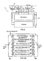
- FIG. 2 shows a preferred embodiment of the hardware circuit for the DES algorithm as a crypto algorithm.
- the hardware circuit 14 in FIG Fig. 2 comprises a first register 20 with a width of 32 bits, a second register 22, which also has a width of 32 bits, a control register (Reg Op) 24, which preferably has a width of 3 bits, a multiplexer device 26 and a S-BOXES block 28.
- the registers are over 32-bit data buses 30a-30d with the multiplexer device 26 and the S-BOXEN block 28, respectively, as in FIG Fig. 2 shown connected.
- the registers 20, 22, one of which is provided for the left half and one for the right half of the bits of a block, depending on the operation, further comprise a rotation capability as indicated by rotation arrows 21, 23 in FIG Fig. 2 is shown schematically. It should be noted that a rotation capability over 28 bits is sufficient for key generation in the DES algorithm, which is why the arrows 21, 23 do not extend to the upper end of the registers 20, 22, but only to the 28th bit of the respective register.
- the operations are carried out by writing data to the two registers 20, 22, and writing the control register 24, the instruction, such as the instruction.
- Bit exchange according to DES table 1 to 6 processed and the result is stored again in the two data registers, from which it can then - can be read - caused by the CPU.
- the two registers are provided with a rotation capability over 28 bits, as has been done.
- the required safety can be achieved for example by redundant design of the multiplexer and S-BOX block including an inverse drive and an inverse output.
- the programming of the DES algorithm or the 2DES algorithm or the 3DES algorithm takes place on the CPU, wherein the hardware circuit 14 is used for all operations of the second subgroup.
- Fig. 3a showed a preferred embodiment of the multiplexer 26 of Fig. 2
- the multiplexer device 26 comprises 6 different multiplexers 31 to 36, which comprise the respective bit exchange operations, ie permutation operations, expansion operations, selection operation, etc. in hardwired form.
- the multiplexer 31 for the initial permutation 61 of FIG Fig. 6 intended.
- This permutation maps 64 input bits to 64 output bits.
- the multiplexer 32 is for the inverse initial permutation, ie for the end permutation 67 of FIG Fig. 6 intended. He, too forms 64 input bits in hard-wired form on 64 output bits.
- the multiplexer 33 is for expansion 70 of FIG Fig. 7 provided in the inner function f.
- the expansion maps 32 input bits to 48 output bits also in hardwired form.
- the multiplexer 34 is for the permutation 75 of Fig. 7 provided and forms 32 input bits to 32 output bits also in hard-wired form.
- the multiplexers 35 and 36 for the bit selection in the context of key generation are also provided in hard-wired form, the multiplexer 35 for the bit selection PC1 56 input bits to 56 output bits, while the multiplexer 36 for the bit selection PC2 48 input bits to 48 output bits maps.
- a multiplexer selection means is provided, which consists of an input selector 38a and an output selector 38b, which are controlled by the bit pattern written in the control register 24.
- the control register 24 is a 3-bit register in a preferred embodiment of the present invention, these 3 bits are sufficient to one of the 6 in Fig. 3a shown multiplexer within the multiplexer device 26 of Fig. 2 to be able to select.
- the control register 24 is executed by the central processing unit 10 of FIG Fig. 1 as part of the flow control to select the correct operation as part of the crypto algorithm flow.
- Fig. 3b shows an alternative embodiment for implementing the multiplexer 26 of Fig. 2
- the multiplexer comprises a number of individual multiplexers (80a, 80b, 80c, ..., 80i), the number of individual multiplexers is equal to the number of input bits, and wherein each single multiplexer has an output by which an output bit of an operation is defined. Further, each single multiplexer has an input having a number of input lines, the number of input lines being equal to or less than the number of operations to be performed by the multiplexer, and each single multiplexer being controllable by the control register to select one of the number of input lines Output to connect.
- the first single multiplexer always specifies the first bit of permutations / selections or expansions to be performed.
- the uppermost multiplexer thus selects which input bit the new output bit should be, depending on the applied selection signal.
- the second highest multiplexer does this for the output bit 2, etc. Since not every operation has a 64 bit wide output, not every multiplexer has to have 6 inputs, but can and preferably will also have fewer inputs.
- Fig. 4 shows a more detailed representation of the S-BOXEN device 28 of Fig. 4
- the S-BOXEN device comprises the 8 S-BOXES S-BOX 1 to S-BOX 8 of the DES algorithm, each receiving 6 bits as an input address and outputting 4 bits of output data.
- the S-BOXES are hardwired to the 48-bit input bus and output-wired to the 32-bit output bus as well, such that an automatic allocation of addresses for one of the 8 S-BOXES based on the significance of the bits on the 48-bit wide input bus.
- the flow of the DES algorithm will now be described with reference to the flowchart of FIG Fig. 6 using the central processing unit 10 and the hardware circuit 14.
- the 64-bit input data block is obtained from the central processing unit and fed to the two registers 20, 22.
- the control register 24 is driven to select the multiplexer 31 of the multiplexer device 26.
- the 64 bits to be inverted are fed from the registers 20, 22 into the multiplexer 31, resulting in 64 output bits which are again written to the registers 20, 22 and thus overwrite the input data therewith.
- the contents of the register 22 are supplied to the multiplexer 26 after rewriting the control register 24 to perform the expansion 70.
- the result of the expansion 70 is then written back to the register 22 and read by the central processing unit to use the first round key to extract the XOR 71 of FIG Fig. 7 can perform.
- the 48 bits that the CPU has calculated due to the XOR connection with the round key represent the addresses for the SBOX access.
- the XOR combination with the round key is thus the address calculation for the SBOX access.
- the 48 address bits for the 8 S-BOXES are then written back into the two registers 20, 22 by the CPU and fed to the S-BOX device 28, which will typically be read-only, to output the bits (74 in Fig. 7 ), which are rewritten, for example, in the register B, and then again, after appropriate re-description of the control register 24 of the multiplexer device to be supplied, wherein the control register 24 is described such that the multiplexer means the multiplexer 34th for the permutation 75 of Fig. 7 selects.
- the 32 output bits are written back to register B.
- the central processing unit reads the Contents of register B 22 off.
- the CPU reads the contents of register A 20 to perform XOR operations 64 of FIG Fig. 6 to get new input data for the next round, which will be executed the same as the first round, but now using the key for the second round.
- the 64-bit key K is read from the central processing unit into the two registers A, B. Thereafter, the longitudinal shift values for the 28-bit rotations are defined, and then, after appropriate description of the control register 24 by the central processing unit, perform the bit selections through the multiplexers 35 and 36, the results of which are written to the registers 20, 22, where then the corresponding rotations take place.
- the hardware circuit can be used accordingly for DES decryption.
Landscapes
- Engineering & Computer Science (AREA)
- Computer Security & Cryptography (AREA)
- Computer Networks & Wireless Communication (AREA)
- Signal Processing (AREA)
- Storage Device Security (AREA)
Abstract
Claims (20)
- Dispositif pour exécuter un algorithme cryptographique, l'algorithme cryptographique présentant un groupe d'opérations comprenant un premier et un deuxième sous-groupe, aux caractéristiques suivantes:une unité de traitement centrale (10) destinée à exécuter le premier sous-groupe et à commander le déroulement de l'algorithme cryptographique;un circuit de matériel (14) destiné à exécuter le deuxième sous-groupe, le circuit de matériel (14) présentant un premier registre (20) à aptitude à la rotation (21), un deuxième registre (22) à aptitude à la rotation (23), un moyen multiplexeur (26), une mémoire à substitution (28) destinée à mémoriser une règle de substitution de bits, et un registre de commande (24) destiné à commander le moyen multiplexeur (26) en fonction d'un modèle de bits écrit dans le registre de commande (24) par l'unité de traitement centrale (10), et le premier registre (20) et le deuxième registre (22) étant reliés à un bus de données (12), au moyen multiplexeur (26) et à la mémoire à substitution (28); etle bus de données (12) étant disposé entre l'unité de traitement centrale et le circuit de matériel.
- Dispositif selon la revendication 1, dans lequel le premier sous-groupe présente des opérations arithmétiques et/ou logiques, et dans lequel le deuxième sous-groupe présente des opérations de rotation, des opérations de permutation, des opérations d'expansion, des opérations de sélection ou des opérations de substitution.
- Dispositif selon la revendication 1 ou 2, dans lequel l'algorithme cryptographique est à base de passages, à partir d'une clé de sortie pour chaque passage pouvant être générée une clé de passage à l'aide d'une rotation et d'une sélection de bits, le moyen multiplexeur présentant un multiplexeur de clé (35, 36) pour exécuter la sélection de bits.
- Dispositif selon l'une des revendications précédentes, dans lequel l'algorithme cryptographique comprend, comme opération, une permutation initiale (61) d'un bloc à crypter à partir de données d'entrée, le moyen multiplexeur présentant un multiplexeur de permutation initiale (31) pour exécuter la permutation initiale.
- Dispositif selon l'une des revendications précédentes, dans lequel l'algorithme cryptographique comprend une permutation finale (67), pour obtenir un bloc de données à crypter, le moyen multiplexeur présentant un multiplexeur de permutation finale (32), pour exécuter la permutation finale.
- Dispositif selon l'une des revendications précédentes, dans lequel l'algorithme cryptographique présente une opération d'expansion (70), le moyen multiplexeur présentant un multiplexeur d'expansion (33) pour exécuter l'expansion.
- Dispositif selon l'une des revendications précédentes, dans lequel l'algorithme cryptographique est à base de passages et présente, dans chaque passage, une permutation, le moyen multiplexeur présentant un multiplexeur de permutation (34), pour exécuter l'opération de permutation.
- Dispositif selon la revendication 1, dans lequel les adresses pour l'opération de substitution de bits sont calculées à l'aide de bits à substituer, le calcul des adresses pouvant être réalisé dans le moyen de traitement central (10) par couplage XOR avec une clé de passage.
- Dispositif selon l'une des revendications précédentes, dans lequel l'algorithme cryptographique présente au moins une opération XOR (71, 64), l'opération XOR pouvant être exécutée dans le moyen de traitement central (10).
- Dispositif selon l'une des revendications précédentes,
dans lequel l'algorithme cryptographique est un algorithme DES. - Dispositif selon la revendication 1, dans lequel le moyen multiplexeur présente plusieurs multiplexeurs individuels (31, 32, 33, 34, 35, 36), chaque multiplexeur individuel étant réalisé pour exécuter une opération d'expansion (70), une opération de permutation (61, 67, 75) ou une opération de sélection de bits.
- Dispositif selon la revendication 1, dans lequel le moyen multiplexeur présente un nombre de multiplexeurs individuels (80a, 80b, 80c, ..., 80i), le nombre de multiplexeurs individuels étant égal au nombre de bits d'entrée, et chaque multiplexeur individuel présentant une sortie par laquelle est défini un bit de sortie d'une opération, et chaque multiplexeur individuel présentant une entrée présentant un nombre de lignes d'entrée, le nombre de lignes d'entrée étant égal ou inférieur au nombre d'opérations à exécuter par le moyen multiplexeur, et chaque multiplexeur individuel pouvant être commandé par le registre de commande, pour connecter l'un parmi le nombre de lignes d'entrée à la sortie.
- Dispositif selon la revendication 1, 11 ou 12, dans lequel l'algorithme cryptographique est un algorithme DES,
dans lequel le premier registre (20) et le deuxième registre (22) sont deux registres de 32 bits,
dans lequel le registre de commande (24) est un registre de 3 bits, et
dans lequel les liaisons de données entre le premier registre et le deuxième registre et le moyen multiplexeur (26) ou la mémoire à substitution (28) sont des liaisons à 32 bits. - Dispositif selon l'une des revendications précédentes,
dans lequel le moyen de traitement central est réalisé de manière à être sûr contre des attaques externes; - Dispositif selon l'une des revendications précédentes,
dans lequel le circuit de matériel (14) est réalisé de manière à être sécurisé contre des attaques externes; - Dispositif selon l'une des revendications précédentes, qui est intégré avec d'autres composants sur un circuit intégré, l'unité de traitement centrale (10) étant par ailleurs réalisée de manière à interagir avec d'autres composants ou à commander les autres composants.
- Dispositif selon la revendication 14, dans lequel le circuit intégré est un CI de sécurité ou est prédestiné à une carte à puce.
- Procédé pour exécuter un algorithme cryptographique, l'algorithme cryptographique présentant un groupe d'opérations comprenant un premier et un deuxième sous-groupe, à l'aide d'une unité de traitement centrale (10) et un circuit de matériel (14) qui est relié à l'unité de traitement centrale (10) par un bus de données (12), le circuit de matériel (14) présentant un premier registre (20) à aptitude à la rotation (21), un deuxième registre (22) à aptitude à la rotation (23), un moyen multiplexeur (26), une mémoire à substitution (28) destinée à mémoriser une règle de substitution de bits, et un registre de commande (24) destiné à commander le moyen multiplexeur (26) en fonction d'un modèle de bits écrit dans le registre de commande (24) par l'unité de traitement centrale (1.0), et le premier registre (20) et le deuxième registre (22) étant reliés au bus de données (12), au moyen multiplexeur (26) et à la mémoire à substitution (28); aux étapes suivantes consistant à:dans l'unité de traitement centrale (10), alimenter les données d'entrée pour une opération du deuxième sous-groupe vers le circuit de matériel (14) et obtenir un résultat de l'opération du circuit de matériel (14);dans le circuit de matériel (14), exécuter l'opération du deuxième sous-groupe avec les données d'entrée pour l'opération alimentées par l'unité de traitement centrale (10); etexécuter une opération du premier sous-groupe ainsi qu'une commande de déroulement de l'algorithme cryptographique dans l'unité de traitement centrale.
- Procédé selon la revendication 18, dans lequel l'algorithme cryptographique est un algorithme DES, le premier sous-groupe présentant des opérations arithmétiques et/ou logiques, et le deuxième sous-groupe présentant une opération de rotation, une opération de permutation, une opération d'expansion, une opération de sélection ou une opération de substitution.
- Procédé selon la revendication 18 ou 19, dans lequel l'algorithme cryptographique présente un couplage XOR avec une clé, le couplage XOR pouvant être réalisé dans l'unité de traitement centrale.
Applications Claiming Priority (3)
| Application Number | Priority Date | Filing Date | Title |
|---|---|---|---|
| DE2002131195 DE10231195A1 (de) | 2002-07-10 | 2002-07-10 | Vorrichtung und Verfahren zum Durchführen eines Kryptoalgorithmus |
| DE10231195 | 2002-07-10 | ||
| PCT/EP2003/007135 WO2004008682A1 (fr) | 2002-07-10 | 2003-07-03 | Dispositif et procede pour executer un algorithme cryptographique |
Publications (2)
| Publication Number | Publication Date |
|---|---|
| EP1510034A1 EP1510034A1 (fr) | 2005-03-02 |
| EP1510034B1 true EP1510034B1 (fr) | 2011-04-06 |
Family
ID=30009882
Family Applications (1)
| Application Number | Title | Priority Date | Filing Date |
|---|---|---|---|
| EP03763702A Expired - Lifetime EP1510034B1 (fr) | 2002-07-10 | 2003-07-03 | Dispositif et procédé pour exécuter un algorithme cryptographique |
Country Status (5)
| Country | Link |
|---|---|
| EP (1) | EP1510034B1 (fr) |
| AU (1) | AU2003249952A1 (fr) |
| DE (2) | DE10231195A1 (fr) |
| TW (1) | TWI292274B (fr) |
| WO (1) | WO2004008682A1 (fr) |
Family Cites Families (2)
| Publication number | Priority date | Publication date | Assignee | Title |
|---|---|---|---|---|
| US6028939A (en) * | 1997-01-03 | 2000-02-22 | Redcreek Communications, Inc. | Data security system and method |
| US7120799B2 (en) * | 2000-12-15 | 2006-10-10 | International Business Machines Corporation | Method and apparatus for dual hardware and software cryptography |
-
2002
- 2002-07-10 DE DE2002131195 patent/DE10231195A1/de not_active Withdrawn
-
2003
- 2003-07-03 WO PCT/EP2003/007135 patent/WO2004008682A1/fr not_active Ceased
- 2003-07-03 DE DE50313602T patent/DE50313602D1/de not_active Expired - Lifetime
- 2003-07-03 EP EP03763702A patent/EP1510034B1/fr not_active Expired - Lifetime
- 2003-07-03 AU AU2003249952A patent/AU2003249952A1/en not_active Abandoned
- 2003-07-07 TW TW92118520A patent/TWI292274B/zh not_active IP Right Cessation
Also Published As
| Publication number | Publication date |
|---|---|
| TWI292274B (en) | 2008-01-01 |
| TW200402223A (en) | 2004-02-01 |
| DE10231195A1 (de) | 2004-02-05 |
| AU2003249952A1 (en) | 2004-02-02 |
| DE50313602D1 (de) | 2011-05-19 |
| EP1510034A1 (fr) | 2005-03-02 |
| WO2004008682A1 (fr) | 2004-01-22 |
Similar Documents
| Publication | Publication Date | Title |
|---|---|---|
| DE60105788T2 (de) | AES Verschlüsselungsschaltung | |
| DE69900980T2 (de) | Verfahren und vorrichtung zur ausführung von verschiebungsoperationen mit gepackten daten | |
| DE3885123T2 (de) | Anordnung und Verfahren für Kryptographie mit Anwendung. | |
| DE3689510T2 (de) | Einrichtung und Verfahren zur Datenverschleierung. | |
| DE102005012098B4 (de) | Datenchiffrierprozessor sowie AES-Chiffriersystem und AES-Chiffrierverfahren | |
| DE602005002632T2 (de) | Schlüsselmaskierung für kryptographische Prozesse mittels einer Kombination von Zufallsmaskenwerten | |
| DE60121284T2 (de) | Verfahren und Vorrichtung zur Ausführung einer kryptographischen Funktion | |
| EP0986872B1 (fr) | Dispositif de mise en oeuvre d'un procede de codage de blocs | |
| EP1246043A2 (fr) | Procédé de transfert de données sur un bus de données | |
| DE102007052656A1 (de) | Digital-Verschlüsselungs-Hardware-Beschleuniger | |
| DE69026784T2 (de) | Verfahren und Einrichtung zur Verschlüsselung mittels Modulo 2-Addition und Blocksubstitution | |
| DE69320246T2 (de) | Hardware-Verschlüsselungsschaltung unter Verwendung von mehreren linearen Transformationsausführungen | |
| DE60301750T2 (de) | Vorrichtung zur Erzeugung eines erweiterten Schlüssels, Verschlüsselungsvorrichtung und Verschlüsselungssystem | |
| DE102005010779B4 (de) | Schlüsseldispositionsvorrichtung und System zur Ver-/Entschlüsselung von Daten | |
| DE10232348A1 (de) | Integrierte Halbleiterschaltung mit interner Busdatenübertragung und zugehöriges Datenübertragungsverfahren | |
| DE10324422B4 (de) | Verfahren und Vorrichtung zur Abbildung eines abzubildenden Eingangswertes auf einen verschlüsselten abgebildeten Ausgangswert | |
| DE69523490T2 (de) | Maskengenerator | |
| DE102004018874B4 (de) | Verfahren und Vorrichtung zum Bestimmen eines Ergebnisses | |
| EP1676394A1 (fr) | Procede et dispositif de chiffrement/dechiffrement | |
| EP1668817A1 (fr) | Procede et dispositif de chiffrement et de dechiffrement | |
| DE60128309T2 (de) | Schaltung zur Erzeugung eines Verschlüsselungsnebenschlüssels | |
| DE10352680A1 (de) | Verschlüsselungsvorrichtung und Verschlüsselungsverfahren | |
| EP1510034A1 (fr) | Dispositif et procede pour executer un algorithme cryptographique | |
| DE60034944T2 (de) | Gegenmassnahmeverfahren in einer geheimen und dynamischen Verschlüsselungsalgorithmus ausführenden elektronischen Schaltung | |
| DE60302249T2 (de) | Aes mixcolumn transformation |
Legal Events
| Date | Code | Title | Description |
|---|---|---|---|
| PUAI | Public reference made under article 153(3) epc to a published international application that has entered the european phase |
Free format text: ORIGINAL CODE: 0009012 |
|
| 17P | Request for examination filed |
Effective date: 20041213 |
|
| AK | Designated contracting states |
Kind code of ref document: A1 Designated state(s): AT BE BG CH CY CZ DE DK EE ES FI FR GB GR HU IE IT LI LU MC NL PT RO SE SI SK TR |
|
| AX | Request for extension of the european patent |
Extension state: AL LT LV MK |
|
| DAX | Request for extension of the european patent (deleted) | ||
| RBV | Designated contracting states (corrected) |
Designated state(s): DE FR |
|
| RAP1 | Party data changed (applicant data changed or rights of an application transferred) |
Owner name: INFINEON TECHNOLOGIES AG |
|
| GRAP | Despatch of communication of intention to grant a patent |
Free format text: ORIGINAL CODE: EPIDOSNIGR1 |
|
| RTI1 | Title (correction) |
Free format text: DEVICE AND METHOD FOR PERFORMING A CRYPTOALGORITHM |
|
| GRAS | Grant fee paid |
Free format text: ORIGINAL CODE: EPIDOSNIGR3 |
|
| GRAA | (expected) grant |
Free format text: ORIGINAL CODE: 0009210 |
|
| AK | Designated contracting states |
Kind code of ref document: B1 Designated state(s): DE FR |
|
| REF | Corresponds to: |
Ref document number: 50313602 Country of ref document: DE Date of ref document: 20110519 Kind code of ref document: P |
|
| REG | Reference to a national code |
Ref country code: DE Ref legal event code: R096 Ref document number: 50313602 Country of ref document: DE Effective date: 20110519 |
|
| PLBE | No opposition filed within time limit |
Free format text: ORIGINAL CODE: 0009261 |
|
| STAA | Information on the status of an ep patent application or granted ep patent |
Free format text: STATUS: NO OPPOSITION FILED WITHIN TIME LIMIT |
|
| 26N | No opposition filed |
Effective date: 20120110 |
|
| REG | Reference to a national code |
Ref country code: DE Ref legal event code: R097 Ref document number: 50313602 Country of ref document: DE Effective date: 20120110 |
|
| REG | Reference to a national code |
Ref country code: FR Ref legal event code: PLFP Year of fee payment: 14 |
|
| REG | Reference to a national code |
Ref country code: FR Ref legal event code: PLFP Year of fee payment: 15 |
|
| REG | Reference to a national code |
Ref country code: FR Ref legal event code: PLFP Year of fee payment: 16 |
|
| PGFP | Annual fee paid to national office [announced via postgrant information from national office to epo] |
Ref country code: FR Payment date: 20180725 Year of fee payment: 16 |
|
| PG25 | Lapsed in a contracting state [announced via postgrant information from national office to epo] |
Ref country code: FR Free format text: LAPSE BECAUSE OF NON-PAYMENT OF DUE FEES Effective date: 20190731 |
|
| PGFP | Annual fee paid to national office [announced via postgrant information from national office to epo] |
Ref country code: DE Payment date: 20210922 Year of fee payment: 19 |
|
| REG | Reference to a national code |
Ref country code: DE Ref legal event code: R119 Ref document number: 50313602 Country of ref document: DE |
|
| PG25 | Lapsed in a contracting state [announced via postgrant information from national office to epo] |
Ref country code: DE Free format text: LAPSE BECAUSE OF NON-PAYMENT OF DUE FEES Effective date: 20230201 |