EP1509853B1 - Topology modeler - Google Patents
Topology modeler Download PDFInfo
- Publication number
- EP1509853B1 EP1509853B1 EP03736773.7A EP03736773A EP1509853B1 EP 1509853 B1 EP1509853 B1 EP 1509853B1 EP 03736773 A EP03736773 A EP 03736773A EP 1509853 B1 EP1509853 B1 EP 1509853B1
- Authority
- EP
- European Patent Office
- Prior art keywords
- feature
- model
- mesh model
- surface point
- modeling
- Prior art date
- Legal status (The legal status is an assumption and is not a legal conclusion. Google has not performed a legal analysis and makes no representation as to the accuracy of the status listed.)
- Expired - Lifetime
Links
Images


Classifications
-
- G—PHYSICS
- G06—COMPUTING OR CALCULATING; COUNTING
- G06T—IMAGE DATA PROCESSING OR GENERATION, IN GENERAL
- G06T17/00—Three-dimensional [3D] modelling for computer graphics
- G06T17/20—Finite element generation, e.g. wire-frame surface description, tesselation
-
- G—PHYSICS
- G06—COMPUTING OR CALCULATING; COUNTING
- G06F—ELECTRIC DIGITAL DATA PROCESSING
- G06F17/00—Digital computing or data processing equipment or methods, specially adapted for specific functions
- G06F17/10—Complex mathematical operations
Definitions
- This invention relates generally to computer-aided modeling and more particularly to a topology modeler.
- FEA Finite Element Analysis
- a feature associated with the device such as an air intake vent positioned over the hood, may be modeled by incorporating the shape of the feature into the FEA process. Because modeling a feature as a part of the mesh requires a more complex mesh having more elements, such a modeling adds complexity to the FEA process.
- a method for modeling a feature associated with a deformed material includes generating a first mesh model modeling a material in a pre-deformation configuration.
- the method also includes defining a model of the feature with respect to the first mesh model.
- the model comprises a plurality of points.
- the method also includes generating, by performing a finite element analysis, a second mesh model modeling the material in a deformed configuration.
- the method also includes modeling the response of the feature to the deformation of the material modeled by the second mesh model.
- the act of modeling the response includes measuring a distance between at least one of the plurality of points and a surface point of the first mesh model along a vector that is normal to the surface of the first mesh model.
- the vector that is normal to the surface of the first mesh model also intersects the at least one of the plurality of points and the surface point.
- the act of modeling the response also includes determining the location of the surface point.
- the act of modeling the response also includes locating the same surface point on the second mesh model as the surface point on the first mesh model.
- the act of modeling the response also includes determining a new location for a new point corresponding to the at least one of the plurality of points. The new location located at the measured distance away from the same surface point of the second mesh model along a vector that is normal to the second mesh model.
- the vector that is normal to the second mesh model intersects the same surface point on the second mesh model.
- Some embodiments of the invention provide numerous technical advantages. Some embodiments may benefit from some, none, or all of these advantages. For example, according to one embodiment, a model of the feature with respect to the deformed material may be generated without complicating the FEA process, which reduces the required computing power and time for performing the FEA. According to another embodiment, a user may select other features having different shapes to place on the deformed material without using the FEA process.
- FIGURES 1A through 3C of the drawings like numerals being used for like and corresponding parts of the various drawings.
- FIGURE 1A is a schematic diagram illustrating an embodiment of a computer system 10 for performing finite element analysis ("FEA") that may benefit from the teachings of the present invention.
- System 10 includes a computer 14 that is coupled to one or more input devices 18 and one or more output devices 20.
- a user 24 has access to system 10 and may utilize input devices 18 to input data and generate and edit a drawing 28 that may be displayed by any or all of output devices 20.
- examples of input device 18 are a keyboard and a mouse; however, input device 18 may take other forms, including a stylus, a scanner, or any combination thereof.
- Examples of output devices 20 are a monitor of any type and a printer; however, output device 16 may take other forms, including a plotter. Any suitable visual display unit, such as a liquid crystal display (“LCD”) or cathode ray tube (“CRT”) display, that allows user 24 to view drawing 28, may be a suitable output device 20.
- LCD liquid crystal display
- CRT cathode ray tube
- FIGURE 1B is a block diagram of computer 14 for use in performing FEA according to one embodiment of the present invention.
- computer 14 includes a processor 30 and a memory 34 storing a FEA software program 38.
- Computer 14 also includes one or more data storage units 40 for storing data related to FEA software program 38 or other data.
- Processor 30 is coupled to memory 34 and data storage unit 40.
- Processor 30 is operable to execute the logic of FEA software program 38 and access data storage unit 40 to retrieve or store data relating to drawings.
- Examples of processor 30 are the PentiumTM series processors, available from Intel Corporation.
- FEA software program 38 is a computer program that allows user 18 to model a device through FEA using computer 14.
- FEA software program 38 may be a part of a drawing application, such as a Computer-Aided Drafting ("CAD") package, or exist as an independent computer application.
- FEA software program 38 may include a function for modeling the topology of the device. The topology modeling funciton may exist as a separate application.
- “Topology” refers to the variation of the shape of a device due to its associated features.
- a “feature” refers any structures and voids that are aligned with any portion of the device.
- a feature may be on or off of the surface of the device.
- a feature may also be inside of the device.
- FEA software program may by operable to model the topology of the device as well as the device itself through the process of FEA. However, the topology function may be served by a separate application that is bundled with FEA software program 38.
- FIGURES 2A and 2B graphically illustrate the forming of a material used to form a device that has an associated feature.
- An example of a forming process includes stamping a hood of an automobile out of a material such as sheet metal.
- the hood of the automobile may have an associated feature overlying the hood, such as an air intake that increases the flow of air into the combustion chamber of the engine.
- a feature may have other shapes and sizes.
- One or more boundary conditions may be imposed on mesh 50A to appropriately displace portions of mesh 50A so that mesh 50A models the displacement of the material.
- Mesh 50A may be generated by a FEA software program or an associated mesh generator (not explicitly shown).
- Model 60A may be generated by the FEA software program or any other application operable to generate a model of a feature, such as model 60A.
- Different materials may experience different type and level of displacements. For example, rubber may experience a more drastic displacement in its edges and the surrounding areas of a particular region that is moved because rubber has a higher degree of elasticity.
- different boundary conditions may be imposed so that different restrictions and movements may be imposed on mesh 50A. Applying a different set of boundary conditions would result in a final mesh having a different shape than that of mesh 50B shown in FIGURE 2B .
- Model 60B may be generated by the FEA software program or any other application operable to generate a model of a feature, such as model 60B.
- a conventional modeling method may model the feature as a part of the FEA process.
- Such a modeling process complicates an already complicated FEA process that requires repeated calculations of a myriad of equations. Thus, the required computing power and time increases. Additionally, modeling a feature as a part of a FEA process limits a user's ability to select other features having different shapes to place on the deformed material because the entire process of FEA may have to be repeated for each selection.
- a method, an apparatus, and a system are provided for modeling a feature by using the respective normal distances between the points of the feature and the initial mesh to model the feature relative to the final mesh. This is advantageous because a feature may be modeled relative to the formed material without increasing the computing power and time that may be required to perform a more complicated FEA.
- a user may select other features having different shapes to place on the deformed material without using the FEA process. Additional details of example embodiments of the system and method are described in greater detail below in conjunction with FIGURES 3A through 3C .
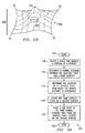
- FIGURE 3A is a flowchart illustrating one embodiment of a method 100 of modeling the shape of a feature with respect to a mesh model. An embodiment of method 100 is described in conjunction with FIGURE 3B , which is a schematic diagram graphically illustrating an embodiment of method 100.
- Method 100 starts at step 104.
- a point 130 that models a portion of the feature is selected.
- point 130 may represent a point that is positioned on a perimeter of the feature. However, any point that represents the shape of the feature prior to the displacement of the material may be selected.
- a normal distance 134 between selected point 130 and the surface of element 58A is determined.
- a "normal distance” between a point and a surface refers to the distance between the point along the normal vector of a surface that intersects the point and a point on the surface.
- a normal vector 140 intersects with selected point 130.
- Normal vector 140 is normal to element 58A at a surface point 138A that is located on element 58A.
- normal distance 134 referred to by letter “d” in FIGURE 3B , is the distance between selected point 130 and surface point 138A along normal vector 140.
- the location of surface point 138A on element 58A is determined.
- a Bezier Patch may be applied on element 58A as a system of determining the relative location of surface point 138A; additional details of the Bezier Patch is provided below in conjunction with FIGURE 3C .
- a surface point 138B on the deformed element 58B having the same relative location, relative to the deformed element 58B, as the determined location of step 114 is located.
- FIGURE 3B illustrates surface points 138A and 138B as separate points, surface points 138A and 138B represent a same, single point of a feature. As such, surface points 138A and 138B are the same surface point. Illustrating the same, single point as point 138A and 138B depicts the global displacement of element 58A and points of the element 58A due to the displacement of an entire mesh. Because surface points 138A and 138B represent the same, single point, the relative location, with regard to elements 58A and 58B, of the point within element 58A and corresponding element 58B stays the same.
- a new point 150 is positioned along a normal vector 154 that intersects with surface point 138B and away from surface point 138B by the same determined normal distance 134.
- Normal vector 154 is normal to the surface of element 58B and intersects with both points 138B and 150.
- Modeling the features by offsetting a point by a normal distance determined from a previous model of the feature is advantageous because a model of the feature with respect to the deformed material may be generated without complicating the FEA process. This reduces the required computing power and time for performing the FEA. Additionally, in some embodiments, other features having different shapes may be modeled according to the deformed material without running the entire FEA for each selected feature shape. The FEA process does not have to be rerun because the feature modeling process is not tied into the FEA process.
- steps 108 through 120 may be repeated until the displaced shape of the entire feature is adequately modeled, as determined by one skilled in the art. For example, in modeling a curve of a feature, a set of points that outlines the curve may be determined. Then, for each point of the set, steps 108 through 120 may be performed. In another example, in modeling a surface of a feature, a set of curves may be sampled from the surface. Then, for each curve, a set of points that outlines the curve may be determined. Then, for each point of the set, steps 108 through 120 may be performed.
- FIGURE 3C is a schematic diagram illustrating one embodiment of a point location system 62.
- An element of a mesh may have a set of nodes 160. Each node 160 is used to as a reference point for displacement of an element modeled by the FEA process.
- element 58A has twelve nodes 160. However, more or less nodes 160 may be designated for each element 58A of mesh 50A. Using these nodes 160, a Bezier Patch, such as a patch 62A, may be applied to element 58A.
- a "Bezier Patch" refers to a grid system that uses the designated nodes 160 as location references, where the position of any point on an element, such as surface points 138A and 138B, may be expressed relative to nodes 160.
- the lower left corner node 160 of element 58A has a location value of [3][0], as shown on patch 62A.
- a location that is half way between location value [3][0] and location value [3] [1] (which is the location that is depicted immediately to the right of location [3] [0]) has a location value of [3] [1/2].
- steps 114 and 118 of method 100 may be performed by using a relative location system, such as patch 62.
- a relative location system such as patch 62.
- point 138A may be assigned a location value of [2][1] according to patch 62A of element 58A.
- the same point 138B may be located on element 58B by using patch 62B and the location value of [2][1].
Landscapes
- Engineering & Computer Science (AREA)
- Physics & Mathematics (AREA)
- General Physics & Mathematics (AREA)
- Theoretical Computer Science (AREA)
- Software Systems (AREA)
- Mathematical Physics (AREA)
- Geometry (AREA)
- Data Mining & Analysis (AREA)
- Computer Graphics (AREA)
- Algebra (AREA)
- Computational Mathematics (AREA)
- Mathematical Analysis (AREA)
- Mathematical Optimization (AREA)
- Pure & Applied Mathematics (AREA)
- Databases & Information Systems (AREA)
- General Engineering & Computer Science (AREA)
- Processing Or Creating Images (AREA)
- Length Measuring Devices With Unspecified Measuring Means (AREA)
Description
- This invention relates generally to computer-aided modeling and more particularly to a topology modeler.
- Mechanical devices having associated features are frequently designed using Finite Element Analysis ("FEA") software applications. For example, a hood of an automobile formed from a piece of sheet metal may be modeled by a FEA software application. To model the forming of a material into a particular shape, the FEA application may generate a mesh that models the material in its initial state. Then the FEA application incrementally determines the displacement of each element of the mesh based on certain boundary conditions until a resulting mesh models the desired shape of the material.
- A feature associated with the device, such as an air intake vent positioned over the hood, may be modeled by incorporating the shape of the feature into the FEA process. Because modeling a feature as a part of the mesh requires a more complex mesh having more elements, such a modeling adds complexity to the FEA process.
- According to one embodiment of the invention, a method for modeling a feature associated with a deformed material is provided. The method includes generating a first mesh model modeling a material in a pre-deformation configuration. The method also includes defining a model of the feature with respect to the first mesh model. The model comprises a plurality of points. The method also includes generating, by performing a finite element analysis, a second mesh model modeling the material in a deformed configuration. The method also includes modeling the response of the feature to the deformation of the material modeled by the second mesh model. The act of modeling the response includes measuring a distance between at least one of the plurality of points and a surface point of the first mesh model along a vector that is normal to the surface of the first mesh model. The vector that is normal to the surface of the first mesh model also intersects the at least one of the plurality of points and the surface point. The act of modeling the response also includes determining the location of the surface point. The act of modeling the response also includes locating the same surface point on the second mesh model as the surface point on the first mesh model. The act of modeling the response also includes determining a new location for a new point corresponding to the at least one of the plurality of points. The new location located at the measured distance away from the same surface point of the second mesh model along a vector that is normal to the second mesh model. The vector that is normal to the second mesh model intersects the same surface point on the second mesh model.
- Some embodiments of the invention provide numerous technical advantages. Some embodiments may benefit from some, none, or all of these advantages. For example, according to one embodiment, a model of the feature with respect to the deformed material may be generated without complicating the FEA process, which reduces the required computing power and time for performing the FEA. According to another embodiment, a user may select other features having different shapes to place on the deformed material without using the FEA process.
- Other technical advantages may be readily ascertained by one of skill in the art.
- Reference is now made to the following description taken in conjunction with the accompanying drawings, wherein like reference numbers represent like parts, in which:
-
FIGURE 1A is a schematic diagram illustrating an embodiment of a computer system operable to perform a method of finite element analysis according to one embodiment of the present invention; -
FIGURE 1B is a block diagram illustrating an embodiment of a computer shown inFIGURE 1A ; -
FIGURE 2A is a schematic diagram illustrating an embodiment of a model of a feature on a mesh that may be used in a method of finite element analysis; -
FIGURE 2B is a schematic diagram illustrating an embodiment of a model of a feature on a mesh resulting from performing the method of finite element analysis; -
FIGURE 3A is a flowchart illustrating an embodiment of a method of modeling a feature with respect to the mesh modeling a deformed material, as shown inFIGURE 2B ; -
FIGURE 3B is a schematic diagram graphically illustrating an embodiment of the method ofFIGURE 3A ; and -
FIGURE 3C is a schematic diagram illustrating an embodiment of a system for locating a surface point shown inFIGURE 3B . - Embodiments of the invention are best understood by referring to
FIGURES 1A through 3C of the drawings, like numerals being used for like and corresponding parts of the various drawings. -
FIGURE 1A is a schematic diagram illustrating an embodiment of acomputer system 10 for performing finite element analysis ("FEA") that may benefit from the teachings of the present invention.System 10 includes acomputer 14 that is coupled to one ormore input devices 18 and one ormore output devices 20. Auser 24 has access tosystem 10 and may utilizeinput devices 18 to input data and generate and edit adrawing 28 that may be displayed by any or all ofoutput devices 20. - As shown in
FIGURE 1A , examples ofinput device 18 are a keyboard and a mouse; however,input device 18 may take other forms, including a stylus, a scanner, or any combination thereof. Examples ofoutput devices 20 are a monitor of any type and a printer; however, output device 16 may take other forms, including a plotter. Any suitable visual display unit, such as a liquid crystal display ("LCD") or cathode ray tube ("CRT") display, that allowsuser 24 to viewdrawing 28, may be asuitable output device 20. -
FIGURE 1B is a block diagram ofcomputer 14 for use in performing FEA according to one embodiment of the present invention. As illustrated,computer 14 includes aprocessor 30 and amemory 34 storing a FEAsoftware program 38.Computer 14 also includes one or moredata storage units 40 for storing data related to FEAsoftware program 38 or other data. -
Processor 30 is coupled tomemory 34 anddata storage unit 40.Processor 30 is operable to execute the logic of FEAsoftware program 38 and accessdata storage unit 40 to retrieve or store data relating to drawings. Examples ofprocessor 30 are the Pentium™ series processors, available from Intel Corporation. -
Memory 34 anddata storage unit 40 may comprise files, stacks, databases, or other suitable forms of data.Memory 34 anddata storage unit 40 may be random-access memory, read-only memory, CD-ROM, removable memory devices, or any other suitable devices that allow storage and/or retrieval of data.Memory 34 anddata storage unit 40 may be interchangeable and may perform the same functions. - FEA
software program 38 is a computer program that allowsuser 18 to model a device through FEA usingcomputer 14. FEAsoftware program 38 may be a part of a drawing application, such as a Computer-Aided Drafting ("CAD") package, or exist as an independent computer application. FEAsoftware program 38 may include a function for modeling the topology of the device. The topology modeling funciton may exist as a separate application. "Topology" refers to the variation of the shape of a device due to its associated features. A "feature" refers any structures and voids that are aligned with any portion of the device. A feature may be on or off of the surface of the device. A feature may also be inside of the device. In some instances, FEA software program may by operable to model the topology of the device as well as the device itself through the process of FEA. However, the topology function may be served by a separate application that is bundled with FEAsoftware program 38. - FEA
software program 38 may reside in any storage medium, such asmemory 34 ordata storage unit 40.FEA software program 38 may be written in any suitable computer language, including C or C++.FEA software program 38 is operable to allowuser 18 to input boundary conditions, such as an initial position of a curve and a final position of a curve, so that a resulting predicted shape may be displayed onoutput device 20 and/or stored indata storage unit 40. An exampleFEA software program 38 that may incorporate the teachings of the invention is Region Analyzer™, available from Unigraphics Solutions, Inc. -
FIGURES 2A and2B graphically illustrate the forming of a material used to form a device that has an associated feature. An example of a forming process includes stamping a hood of an automobile out of a material such as sheet metal. The hood of the automobile may have an associated feature overlying the hood, such as an air intake that increases the flow of air into the combustion chamber of the engine. However, a feature may have other shapes and sizes. - A
mesh 50A shown inFIGURE 2A is an embodiment of a model of the material prior to the forming operation. Amodel 60A is a model of a feature that is on the material prior to the forming operation.Mesh 50A comprises a plurality ofelements 58A.Element 58A may have a simply shaped geometry, such as a triangle, quadrilateral, or other polygons. Although only quadrilaterals are shown inmesh 50A ofFIGURE 2A , any polygon or a combination of polygons may be used to formmesh 50A to model a particular geometry of the material. In the embodiment shown inFIGURE 2A ,mesh 50A has fourcorners 52 and acenter 53; however, depending on the geometry of a mesh, there may be more orless corners 52. One or more boundary conditions may be imposed onmesh 50A to appropriately displace portions ofmesh 50A so thatmesh 50A models the displacement of the material.Mesh 50A may be generated by a FEA software program or an associated mesh generator (not explicitly shown).Model 60A may be generated by the FEA software program or any other application operable to generate a model of a feature, such asmodel 60A. - Referring to
FIGURE 2B ,mesh 50B illustrates the shape that results from enforcing a set of boundary conditions that operate to fix fourcorners 52 ofmesh 50A and displacingcenter 53 ofmesh 50A in an upward direction.Mesh 50B may be generated by a FEA software program or an associated mesh generator (not explicitly shown). Althoughonly center 53 is displaced upwards, that displacement results in the displacement of the surface of the material that surroundscenter 53 as well as the edges of the material. Thus,elements 58A, which initially represented the areas that surroundcenter 53, are also individually displaced. Thedisplaced elements 58A are illustrated aselements 58B onmesh 50B, where eachelement 58B corresponds to aparticular element 58A. These displacements are reactions to the movement ofcenter 53 while fixingcorners 52. Althoughelements elements 58A and its corresponding one ofelements 58B represents the same corresponding portion of the feature. - Different materials may experience different type and level of displacements. For example, rubber may experience a more drastic displacement in its edges and the surrounding areas of a particular region that is moved because rubber has a higher degree of elasticity. Furthermore, different boundary conditions may be imposed so that different restrictions and movements may be imposed on
mesh 50A. Applying a different set of boundary conditions would result in a final mesh having a different shape than that ofmesh 50B shown inFIGURE 2B . - Because the material has been displaced, as shown by
mesh 50B, the feature is also displaced in response to the displacement ofmesh 50B. The displaced feature is modeled by amodel 60B.Model 60B may be generated by the FEA software program or any other application operable to generate a model of a feature, such asmodel 60B. - To model the resulting shape of the feature after the forming of the material, a conventional modeling method may model the feature as a part of the FEA process. Such a modeling process complicates an already complicated FEA process that requires repeated calculations of a myriad of equations. Thus, the required computing power and time increases. Additionally, modeling a feature as a part of a FEA process limits a user's ability to select other features having different shapes to place on the deformed material because the entire process of FEA may have to be repeated for each selection.
- According to some embodiments of the present invention, a method, an apparatus, and a system are provided for modeling a feature by using the respective normal distances between the points of the feature and the initial mesh to model the feature relative to the final mesh. This is advantageous because a feature may be modeled relative to the formed material without increasing the computing power and time that may be required to perform a more complicated FEA. In some embodiments of the invention, a user may select other features having different shapes to place on the deformed material without using the FEA process. Additional details of example embodiments of the system and method are described in greater detail below in conjunction with
FIGURES 3A through 3C . -
FIGURE 3A is a flowchart illustrating one embodiment of amethod 100 of modeling the shape of a feature with respect to a mesh model. An embodiment ofmethod 100 is described in conjunction withFIGURE 3B , which is a schematic diagram graphically illustrating an embodiment ofmethod 100.Method 100 starts atstep 104. Atstep 108, apoint 130 that models a portion of the feature is selected. In one embodiment,point 130 may represent a point that is positioned on a perimeter of the feature. However, any point that represents the shape of the feature prior to the displacement of the material may be selected. Atstep 110, anormal distance 134 between selectedpoint 130 and the surface ofelement 58A is determined. A "normal distance" between a point and a surface refers to the distance between the point along the normal vector of a surface that intersects the point and a point on the surface. In the embodiment shown inFIGURE 3B , anormal vector 140 intersects with selectedpoint 130.Normal vector 140 is normal toelement 58A at asurface point 138A that is located onelement 58A. Thus,normal distance 134, referred to by letter "d" inFIGURE 3B , is the distance between selectedpoint 130 andsurface point 138A alongnormal vector 140. Atstep 114, the location ofsurface point 138A onelement 58A is determined. In one embodiment, a Bezier Patch may be applied onelement 58A as a system of determining the relative location ofsurface point 138A; additional details of the Bezier Patch is provided below in conjunction withFIGURE 3C . - At
step 118, asurface point 138B on thedeformed element 58B having the same relative location, relative to thedeformed element 58B, as the determined location ofstep 114 is located. AlthoughFIGURE 3B illustrates surface points 138A and 138B as separate points, surface points 138A and 138B represent a same, single point of a feature. As such, surface points 138A and 138B are the same surface point. Illustrating the same, single point aspoint element 58A and points of theelement 58A due to the displacement of an entire mesh. Because surface points 138A and 138B represent the same, single point, the relative location, with regard toelements element 58A andcorresponding element 58B stays the same. - At
step 120, anew point 150 is positioned along anormal vector 154 that intersects withsurface point 138B and away fromsurface point 138B by the same determinednormal distance 134.Normal vector 154 is normal to the surface ofelement 58B and intersects with bothpoints Method 100 stops atstep 124. - Modeling the features by offsetting a point by a normal distance determined from a previous model of the feature is advantageous because a model of the feature with respect to the deformed material may be generated without complicating the FEA process. This reduces the required computing power and time for performing the FEA. Additionally, in some embodiments, other features having different shapes may be modeled according to the deformed material without running the entire FEA for each selected feature shape. The FEA process does not have to be rerun because the feature modeling process is not tied into the FEA process.
- In some embodiments,
steps 108 through 120 may be repeated until the displaced shape of the entire feature is adequately modeled, as determined by one skilled in the art. For example, in modeling a curve of a feature, a set of points that outlines the curve may be determined. Then, for each point of the set, steps 108 through 120 may be performed. In another example, in modeling a surface of a feature, a set of curves may be sampled from the surface. Then, for each curve, a set of points that outlines the curve may be determined. Then, for each point of the set, steps 108 through 120 may be performed. -
FIGURE 3C is a schematic diagram illustrating one embodiment of apoint location system 62. An element of a mesh may have a set ofnodes 160. Eachnode 160 is used to as a reference point for displacement of an element modeled by the FEA process. In one embodiment,element 58A has twelvenodes 160. However, more orless nodes 160 may be designated for eachelement 58A ofmesh 50A. Using thesenodes 160, a Bezier Patch, such as apatch 62A, may be applied toelement 58A. A "Bezier Patch" refers to a grid system that uses the designatednodes 160 as location references, where the position of any point on an element, such as surface points 138A and 138B, may be expressed relative tonodes 160. For example, the lowerleft corner node 160 ofelement 58A has a location value of [3][0], as shown onpatch 62A. A location that is half way between location value [3][0] and location value [3] [1] (which is the location that is depicted immediately to the right of location [3] [0]) has a location value of [3] [1/2]. - When
element 58A is converted toelement 58B by displacement,patch 62A also displaces analogously, as shown by apatch 62B. However, the location value of a particular position on eitherelements left node 160 ofelement 58B still has the location value of [3] [0]. - Referring again to
FIGURES 3A and3B , in one embodiment, steps 114 and 118 ofmethod 100 may be performed by using a relative location system, such aspatch 62. For example, atstep 114,point 138A may be assigned a location value of [2][1] according topatch 62A ofelement 58A. Then atstep 118, thesame point 138B may be located onelement 58B by usingpatch 62B and the location value of [2][1].
Claims (20)
- A computerized method for modeling a feature associated with a deformed material, comprising:generating a first mesh model modeling a material in a pre-deformation configuration;defining a model of the feature with respect to the first mesh model, the model comprising a plurality of points;generating, by performing a finite element analysis, a second mesh model modeling the material in a deformed configuration;modeling the response of the feature to the deformation of the material modeled by the second mesh model, the modeling of the response performed by:measuring a distance between at least one of the plurality of points and a surface point of the first mesh model along a vector normal to the surface of the first mesh model and intersecting the at least one of the plurality of points and the surface point;determining the location of the surface point;locating the same surface point on the second mesh model as the surface point on the first mesh model; anddetermining a new location for a new point corresponding to the at least one of the plurality of points, the new location located at the measured distance away from the same surface point of the second mesh model along a vector that is normal to the second mesh model, the vector intersecting the same surface point on the second mesh model.
- The method of Claim 1, wherein defining the model of the feature comprises using the plurality of points to define the perimeter of the feature.
- The method of Claim 1, wherein the first mesh model comprises a plurality of elements, each of the plurality of elements comprising a set of nodes, and wherein determining the location of the surface point comprises using the set of nodes in a particular element in which the surface point is positioned as a reference.
- The method of Claim 1, wherein modeling the response of the feature comprises modeling the change in the shape and the dimensions of the feature relative to the deformed configuration of the material.
- The method of Claim 1, wherein modeling the response of the feature comprises automatically modeling the response of the feature upon defining the second mesh model.
- The method of Claim 1, wherein defining a model of the feature comprises defining any curves of the feature with the plurality of points.
- The method of Claim 1, wherein modeling the response of the feature comprises repeating the acts included in the act of modeling the response until each of the plurality of points is assigned one respective new point.
- The method of Claim 1, wherein the surface point of the first mesh model has a relative location value, and wherein locating the same surface point comprises locating a surface point on the second mesh model that has the same relative location value as the surface point of the first mesh model.
- An apparatus for modeling displacement of a material, comprising:a software program stored on a computer readable medium and operable, when executed on a processor, to:generate a first mesh model modeling a material in a pre-deformation configuration;define a model of the feature with respect to the first mesh model, the model comprising a plurality of points;generate, by performing a finite element analysis, a second mesh model modeling the material in a deformed configuration;model the response of the feature to the deformation of the material modeled by the second mesh model, wherein the software program is operable to model the response by:measuring a distance between at least one of the plurality of points and a surface point of the first mesh model along a vector normal to the surface of the first mesh model and intersecting the at least one of the plurality of points and the surface point;determining the location of the surface point;locating the same surface point on the second mesh model as the surface point on the first mesh model; anddetermining a new location for a new point corresponding to the at least one of the plurality of points, the new location located at the measured distance away from the same surface point of the second mesh model along a vector that is normal to the second mesh model, the vector intersecting the same surface point on the second mesh model.
- The apparatus of Claim 9, wherein the software program is operable to define the model of the feature by using the plurality of points to define the perimeter of the feature.
- The apparatus of Claim 9, wherein the software program is operable to model the response of the feature by modeling the change in the shape and the dimensions of the feature with respect to the deformed configuration of the material.
- The apparatus of Claim 9, wherein the software is operable to model the response of the feature by automatically modeling the response of the feature upon defining the second mesh model.
- The apparatus of Claim 9, wherein the software is operable to define a model of the feature by defining any curves of the feature with the plurality of points.
- The apparatus of Claim 9, wherein the surface point of the first mesh model has a relative location value, and wherein the software program is operable to locate the same surface point by locating a surface point on the second mesh model that has the same relative location value as the surface point of the first mesh model.
- A system for modeling displacement of a material within a computer-aided analysis environment, comprising:a computer system having a display unit, an input device, and a processor;a computer readable medium coupled to the computer system, the computer readable medium comprising a software program operable to be executed on the processor and to:generate a first mesh model modeling a material in a pre-deformation configuration;define a model of the feature with respect to the first mesh model, the model comprising a plurality of points;generate, by performing a finite element analysis, a second mesh model modeling the material in a deformed configuration;model the response of the feature to the deformation of the material modeled by the second mesh model, wherein the software program is operable to model the response by:measuring a distance between at least one of the plurality of points and a surface point of the first mesh model along a vector normal to the surface of the first mesh model and intersecting the at least one of the plurality of points and the surface point;determining the location of the surface point;locating the same surface point on the second mesh model as the surface point on the first mesh model; anddetermining a new location for a new point corresponding to the at least one of the plurality of points, the new location located at the measured distance away from the same surface point of the second mesh model along a vector that is normal to the second mesh model, the vector intersecting the same surface point on the second mesh model.
- The system of Claim 15, wherein the software program is operable to define the model of the feature by using the plurality of points to define the perimeter of the feature.
- The system of Claim 15, wherein the software program is operable to model the response of the feature by modeling the change in the shape and the dimensions of the feature with respect to the deformed configuration of the material.
- The system of Claim 15, wherein the software is operable to model the response of the feature by automatically modeling the response of the feature upon defining the second mesh model.
- The system of Claim 15, wherein the software is operable to define a model of the feature by defining any curves of the feature with the plurality of points.
- The system of Claim 15, wherein the surface point of the first mesh model has a relative location value, and wherein the software program is operable to locate the same surface point by locating a surface point on the second mesh model that has the same relative location value as the surface point of the first mesh model.
Applications Claiming Priority (3)
| Application Number | Priority Date | Filing Date | Title |
|---|---|---|---|
| US160424 | 2002-05-31 | ||
| US10/160,424 US7222057B2 (en) | 2002-05-31 | 2002-05-31 | Topology modeler |
| PCT/US2003/017191 WO2003102826A2 (en) | 2002-05-31 | 2003-05-30 | Topology modeler |
Publications (2)
| Publication Number | Publication Date |
|---|---|
| EP1509853A2 EP1509853A2 (en) | 2005-03-02 |
| EP1509853B1 true EP1509853B1 (en) | 2013-07-03 |
Family
ID=29583147
Family Applications (1)
| Application Number | Title | Priority Date | Filing Date |
|---|---|---|---|
| EP03736773.7A Expired - Lifetime EP1509853B1 (en) | 2002-05-31 | 2003-05-30 | Topology modeler |
Country Status (7)
| Country | Link |
|---|---|
| US (1) | US7222057B2 (en) |
| EP (1) | EP1509853B1 (en) |
| JP (1) | JP4914004B2 (en) |
| KR (1) | KR100988424B1 (en) |
| AU (1) | AU2003237307A1 (en) |
| CA (1) | CA2488055A1 (en) |
| WO (1) | WO2003102826A2 (en) |
Families Citing this family (7)
| Publication number | Priority date | Publication date | Assignee | Title |
|---|---|---|---|---|
| US7590512B2 (en) * | 2004-09-08 | 2009-09-15 | Carnegie Mellon University | System and method for deformation analysis using inverse pre-deformation of finite element mesh |
| US7398129B2 (en) | 2004-10-07 | 2008-07-08 | Amada Company, Limited | Representation of sheet metal part models |
| KR100701303B1 (en) * | 2005-02-16 | 2007-03-29 | 고려대학교 산학협력단 | Dynamic Simulation and Overcalculation Derivation of Wheel Blowing Process |
| US9152740B1 (en) * | 2012-01-18 | 2015-10-06 | Msc.Software Corporation | Interactive simulation and solver for mechanical, fluid, and electro-mechanical systems |
| US9141734B2 (en) | 2012-11-19 | 2015-09-22 | The Boeing Company | System and method of refining a topological indexed mesh |
| US9965574B2 (en) * | 2013-12-23 | 2018-05-08 | Dassault Systemes Simulia Corp. | CAD-based initial surface geometry correction |
| CN105975683B (en) * | 2016-04-29 | 2019-10-25 | 大连楼兰科技股份有限公司 | A Quick Search Method for Finite Element Mesh Model Update |
Family Cites Families (19)
| Publication number | Priority date | Publication date | Assignee | Title |
|---|---|---|---|---|
| US5390127A (en) | 1992-12-21 | 1995-02-14 | Ford Motor Company | Method and apparatus for predicting post-buckling deformation of sheet metal |
| US5891131A (en) * | 1993-02-01 | 1999-04-06 | Arizona Board Of Regents | Method and apparatus for automated simulation and design of corneal refractive procedures |
| JP3511301B2 (en) * | 1993-06-15 | 2004-03-29 | 株式会社日立製作所 | Surface data generation method |
| US5594651A (en) | 1995-02-14 | 1997-01-14 | St. Ville; James A. | Method and apparatus for manufacturing objects having optimized response characteristics |
| US6064810A (en) * | 1996-09-27 | 2000-05-16 | Southern Methodist University | System and method for predicting the behavior of a component |
| US5886702A (en) * | 1996-10-16 | 1999-03-23 | Real-Time Geometry Corporation | System and method for computer modeling of 3D objects or surfaces by mesh constructions having optimal quality characteristics and dynamic resolution capabilities |
| US6300960B1 (en) * | 1997-08-04 | 2001-10-09 | Pixar Animation Studios | Realistic surface simulation in computer animation |
| JP3208358B2 (en) * | 1997-09-05 | 2001-09-10 | インターナショナル・ビジネス・マシーンズ・コーポレーション | Meshing method and computer |
| FR2771202B1 (en) | 1997-11-19 | 2000-01-21 | Inst Nat Rech Inf Automat | ELECTRONIC IMAGE DATA PROCESSING DEVICE, FOR SIMULATION OF THE DEFORMABLE BEHAVIOR OF AN OBJECT |
| US6426750B1 (en) * | 1998-07-14 | 2002-07-30 | Microsoft Corporation | Run-time geomorphs |
| US6212486B1 (en) | 1998-09-17 | 2001-04-03 | Ford Global Technologies, Inc. | Method of identifying critical elements in fatigue analysis with von mises stress bounding and filtering modal displacement history using dynamic windowing |
| US6198486B1 (en) * | 1998-09-23 | 2001-03-06 | Intel Corporation | Method of using a hybrid error metric for multi-resolution mesh generation |
| US6369815B1 (en) | 1999-04-23 | 2002-04-09 | Spatial Technology, Inc. | Deformable modeling using generalized curve constraints |
| US6718291B1 (en) * | 1999-07-02 | 2004-04-06 | Vadim Shapiro | Mesh-free method and system for modeling and analysis |
| JP3511498B2 (en) * | 2000-06-19 | 2004-03-29 | インターナショナル・ビジネス・マシーンズ・コーポレーション | Mesh generation system, design support system, analysis system, mesh generation method, and storage medium |
| CN1386200A (en) * | 2000-06-29 | 2002-12-18 | 目标储油层公司 | Feature modeling method in a finite element model |
| US6625938B1 (en) * | 2001-06-08 | 2003-09-30 | Carnegie Mellon University | System and method for converting a hex-dominant mesh to an all-hexahedral mesh |
| JP4763934B2 (en) * | 2001-09-06 | 2011-08-31 | 株式会社日本総合研究所 | 3D mesh generation method, rotating machine magnetic field analysis method, 3D mesh generation apparatus, rotating machine magnetic field analysis apparatus, computer program, and recording medium |
| US7324103B2 (en) * | 2001-10-30 | 2008-01-29 | Ford Motor Company | System and method of direct mesh manipulation |
-
2002
- 2002-05-31 US US10/160,424 patent/US7222057B2/en not_active Expired - Lifetime
-
2003
- 2003-05-30 EP EP03736773.7A patent/EP1509853B1/en not_active Expired - Lifetime
- 2003-05-30 CA CA002488055A patent/CA2488055A1/en not_active Abandoned
- 2003-05-30 AU AU2003237307A patent/AU2003237307A1/en not_active Abandoned
- 2003-05-30 KR KR1020047019276A patent/KR100988424B1/en not_active Expired - Fee Related
- 2003-05-30 JP JP2004509842A patent/JP4914004B2/en not_active Expired - Fee Related
- 2003-05-30 WO PCT/US2003/017191 patent/WO2003102826A2/en not_active Ceased
Also Published As
| Publication number | Publication date |
|---|---|
| WO2003102826A2 (en) | 2003-12-11 |
| US20030225553A1 (en) | 2003-12-04 |
| EP1509853A2 (en) | 2005-03-02 |
| KR20050019723A (en) | 2005-03-03 |
| AU2003237307A1 (en) | 2003-12-19 |
| CA2488055A1 (en) | 2003-12-11 |
| KR100988424B1 (en) | 2010-10-18 |
| WO2003102826A3 (en) | 2004-07-29 |
| US7222057B2 (en) | 2007-05-22 |
| AU2003237307A8 (en) | 2003-12-19 |
| JP2005528701A (en) | 2005-09-22 |
| JP4914004B2 (en) | 2012-04-11 |
Similar Documents
| Publication | Publication Date | Title |
|---|---|---|
| KR100974992B1 (en) | Computer strain analyzer | |
| Shephard et al. | Adaptive mesh generation for curved domains | |
| US7275023B2 (en) | System and method of interactively generating a family of mesh models | |
| Wawrzynek et al. | An interactive approach to local remeshing around a propagating crack | |
| US7222057B2 (en) | Topology modeler | |
| US6317704B1 (en) | Method for generating a mesh and a computer therefor | |
| US7467077B2 (en) | Mesh model creating method, simulation apparatus and computer-readable storage medium | |
| CN112381773B (en) | Key cross section data analysis method, device, equipment and storage medium | |
| JPH1196400A (en) | Shape conversion method | |
| JP2002207777A (en) | How to generate a neutral plane model | |
| JP2001034653A (en) | Feature-based macro language for defining customized analysis functions and customized figure functions | |
| JP3220603B2 (en) | Design support equipment | |
| JP2800708B2 (en) | Method for correcting mesh of FEM analysis model | |
| JP3786412B2 (en) | Fillet creation method and 3D CAD program | |
| JP3563927B2 (en) | Temporary storage position determination device and recording medium recording temporary storage position determination program | |
| JPH08305735A (en) | Method and device for estimating cost of parts | |
| JPH10289257A (en) | Modification method of three-dimensional mesh, deformation analysis device, and recording medium | |
| Wawrzynek et al. | Fransys: a software system for the simulation of crack propagation in three dimensions | |
| JPS62263564A (en) | Coordinate grid creation support method and device | |
| JP4089806B2 (en) | Curve generating device and method, and storage medium | |
| JPH11203489A (en) | Method and device for plotting bezier curve and recording medium storing bezier curve plotting program | |
| JP3599209B2 (en) | Building wind prevention measures design system | |
| JP2000187739A (en) | Polygon generation method and computer-readable recording medium storing a program for causing a computer to execute each step of the method | |
| Sankar et al. | Integration of Boundary Element Analysis with Computer Aided Design | |
| JPH11272888A (en) | CAD / CAE equipment |
Legal Events
| Date | Code | Title | Description |
|---|---|---|---|
| PUAI | Public reference made under article 153(3) epc to a published international application that has entered the european phase |
Free format text: ORIGINAL CODE: 0009012 |
|
| 17P | Request for examination filed |
Effective date: 20041223 |
|
| AK | Designated contracting states |
Kind code of ref document: A2 Designated state(s): AT BE BG CH CY CZ DE DK EE ES FI FR GB GR HU IE IT LI LU MC NL PT RO SE SI SK TR |
|
| AX | Request for extension of the european patent |
Extension state: AL LT LV MK |
|
| DAX | Request for extension of the european patent (deleted) | ||
| RAP1 | Party data changed (applicant data changed or rights of an application transferred) |
Owner name: SIEMENS PRODUCT LIFECYCLE MANAGEMENT SOFTWARE INC. |
|
| GRAP | Despatch of communication of intention to grant a patent |
Free format text: ORIGINAL CODE: EPIDOSNIGR1 |
|
| GRAS | Grant fee paid |
Free format text: ORIGINAL CODE: EPIDOSNIGR3 |
|
| GRAA | (expected) grant |
Free format text: ORIGINAL CODE: 0009210 |
|
| AK | Designated contracting states |
Kind code of ref document: B1 Designated state(s): AT BE BG CH CY CZ DE DK EE ES FI FR GB GR HU IE IT LI LU MC NL PT RO SE SI SK TR |
|
| REG | Reference to a national code |
Ref country code: GB Ref legal event code: FG4D |
|
| REG | Reference to a national code |
Ref country code: CH Ref legal event code: EP Ref country code: AT Ref legal event code: REF Ref document number: 620125 Country of ref document: AT Kind code of ref document: T Effective date: 20130715 |
|
| REG | Reference to a national code |
Ref country code: IE Ref legal event code: FG4D |
|
| REG | Reference to a national code |
Ref country code: DE Ref legal event code: R096 Ref document number: 60344411 Country of ref document: DE Effective date: 20130829 |
|
| PG25 | Lapsed in a contracting state [announced via postgrant information from national office to epo] |
Ref country code: SI Free format text: LAPSE BECAUSE OF FAILURE TO SUBMIT A TRANSLATION OF THE DESCRIPTION OR TO PAY THE FEE WITHIN THE PRESCRIBED TIME-LIMIT Effective date: 20130703 |
|
| REG | Reference to a national code |
Ref country code: AT Ref legal event code: MK05 Ref document number: 620125 Country of ref document: AT Kind code of ref document: T Effective date: 20130703 |
|
| REG | Reference to a national code |
Ref country code: NL Ref legal event code: VDEP Effective date: 20130703 |
|
| PG25 | Lapsed in a contracting state [announced via postgrant information from national office to epo] |
Ref country code: AT Free format text: LAPSE BECAUSE OF FAILURE TO SUBMIT A TRANSLATION OF THE DESCRIPTION OR TO PAY THE FEE WITHIN THE PRESCRIBED TIME-LIMIT Effective date: 20130703 Ref country code: CY Free format text: LAPSE BECAUSE OF FAILURE TO SUBMIT A TRANSLATION OF THE DESCRIPTION OR TO PAY THE FEE WITHIN THE PRESCRIBED TIME-LIMIT Effective date: 20130703 Ref country code: BE Free format text: LAPSE BECAUSE OF FAILURE TO SUBMIT A TRANSLATION OF THE DESCRIPTION OR TO PAY THE FEE WITHIN THE PRESCRIBED TIME-LIMIT Effective date: 20130703 Ref country code: SE Free format text: LAPSE BECAUSE OF FAILURE TO SUBMIT A TRANSLATION OF THE DESCRIPTION OR TO PAY THE FEE WITHIN THE PRESCRIBED TIME-LIMIT Effective date: 20130703 Ref country code: PT Free format text: LAPSE BECAUSE OF FAILURE TO SUBMIT A TRANSLATION OF THE DESCRIPTION OR TO PAY THE FEE WITHIN THE PRESCRIBED TIME-LIMIT Effective date: 20131104 |
|
| PG25 | Lapsed in a contracting state [announced via postgrant information from national office to epo] |
Ref country code: FI Free format text: LAPSE BECAUSE OF FAILURE TO SUBMIT A TRANSLATION OF THE DESCRIPTION OR TO PAY THE FEE WITHIN THE PRESCRIBED TIME-LIMIT Effective date: 20130703 Ref country code: ES Free format text: LAPSE BECAUSE OF FAILURE TO SUBMIT A TRANSLATION OF THE DESCRIPTION OR TO PAY THE FEE WITHIN THE PRESCRIBED TIME-LIMIT Effective date: 20131014 Ref country code: NL Free format text: LAPSE BECAUSE OF FAILURE TO SUBMIT A TRANSLATION OF THE DESCRIPTION OR TO PAY THE FEE WITHIN THE PRESCRIBED TIME-LIMIT Effective date: 20130703 Ref country code: GR Free format text: LAPSE BECAUSE OF FAILURE TO SUBMIT A TRANSLATION OF THE DESCRIPTION OR TO PAY THE FEE WITHIN THE PRESCRIBED TIME-LIMIT Effective date: 20131004 |
|
| PG25 | Lapsed in a contracting state [announced via postgrant information from national office to epo] |
Ref country code: DK Free format text: LAPSE BECAUSE OF FAILURE TO SUBMIT A TRANSLATION OF THE DESCRIPTION OR TO PAY THE FEE WITHIN THE PRESCRIBED TIME-LIMIT Effective date: 20130703 Ref country code: RO Free format text: LAPSE BECAUSE OF FAILURE TO SUBMIT A TRANSLATION OF THE DESCRIPTION OR TO PAY THE FEE WITHIN THE PRESCRIBED TIME-LIMIT Effective date: 20130703 Ref country code: EE Free format text: LAPSE BECAUSE OF FAILURE TO SUBMIT A TRANSLATION OF THE DESCRIPTION OR TO PAY THE FEE WITHIN THE PRESCRIBED TIME-LIMIT Effective date: 20130703 Ref country code: SK Free format text: LAPSE BECAUSE OF FAILURE TO SUBMIT A TRANSLATION OF THE DESCRIPTION OR TO PAY THE FEE WITHIN THE PRESCRIBED TIME-LIMIT Effective date: 20130703 Ref country code: CZ Free format text: LAPSE BECAUSE OF FAILURE TO SUBMIT A TRANSLATION OF THE DESCRIPTION OR TO PAY THE FEE WITHIN THE PRESCRIBED TIME-LIMIT Effective date: 20130703 |
|
| PLBE | No opposition filed within time limit |
Free format text: ORIGINAL CODE: 0009261 |
|
| STAA | Information on the status of an ep patent application or granted ep patent |
Free format text: STATUS: NO OPPOSITION FILED WITHIN TIME LIMIT |
|
| PG25 | Lapsed in a contracting state [announced via postgrant information from national office to epo] |
Ref country code: IT Free format text: LAPSE BECAUSE OF FAILURE TO SUBMIT A TRANSLATION OF THE DESCRIPTION OR TO PAY THE FEE WITHIN THE PRESCRIBED TIME-LIMIT Effective date: 20130703 |
|
| 26N | No opposition filed |
Effective date: 20140404 |
|
| REG | Reference to a national code |
Ref country code: DE Ref legal event code: R097 Ref document number: 60344411 Country of ref document: DE Effective date: 20140404 |
|
| PGFP | Annual fee paid to national office [announced via postgrant information from national office to epo] |
Ref country code: DE Payment date: 20140718 Year of fee payment: 12 |
|
| PG25 | Lapsed in a contracting state [announced via postgrant information from national office to epo] |
Ref country code: LU Free format text: LAPSE BECAUSE OF FAILURE TO SUBMIT A TRANSLATION OF THE DESCRIPTION OR TO PAY THE FEE WITHIN THE PRESCRIBED TIME-LIMIT Effective date: 20140530 |
|
| REG | Reference to a national code |
Ref country code: CH Ref legal event code: PL |
|
| PG25 | Lapsed in a contracting state [announced via postgrant information from national office to epo] |
Ref country code: LI Free format text: LAPSE BECAUSE OF NON-PAYMENT OF DUE FEES Effective date: 20140531 Ref country code: MC Free format text: LAPSE BECAUSE OF FAILURE TO SUBMIT A TRANSLATION OF THE DESCRIPTION OR TO PAY THE FEE WITHIN THE PRESCRIBED TIME-LIMIT Effective date: 20130703 Ref country code: CH Free format text: LAPSE BECAUSE OF NON-PAYMENT OF DUE FEES Effective date: 20140531 |
|
| REG | Reference to a national code |
Ref country code: IE Ref legal event code: MM4A |
|
| PG25 | Lapsed in a contracting state [announced via postgrant information from national office to epo] |
Ref country code: IE Free format text: LAPSE BECAUSE OF NON-PAYMENT OF DUE FEES Effective date: 20140530 |
|
| REG | Reference to a national code |
Ref country code: FR Ref legal event code: PLFP Year of fee payment: 13 |
|
| PGFP | Annual fee paid to national office [announced via postgrant information from national office to epo] |
Ref country code: GB Payment date: 20150511 Year of fee payment: 13 |
|
| PGFP | Annual fee paid to national office [announced via postgrant information from national office to epo] |
Ref country code: FR Payment date: 20150513 Year of fee payment: 13 |
|
| REG | Reference to a national code |
Ref country code: DE Ref legal event code: R119 Ref document number: 60344411 Country of ref document: DE |
|
| PG25 | Lapsed in a contracting state [announced via postgrant information from national office to epo] |
Ref country code: DE Free format text: LAPSE BECAUSE OF NON-PAYMENT OF DUE FEES Effective date: 20151201 |
|
| PG25 | Lapsed in a contracting state [announced via postgrant information from national office to epo] |
Ref country code: BG Free format text: LAPSE BECAUSE OF FAILURE TO SUBMIT A TRANSLATION OF THE DESCRIPTION OR TO PAY THE FEE WITHIN THE PRESCRIBED TIME-LIMIT Effective date: 20130703 |
|
| PG25 | Lapsed in a contracting state [announced via postgrant information from national office to epo] |
Ref country code: HU Free format text: LAPSE BECAUSE OF FAILURE TO SUBMIT A TRANSLATION OF THE DESCRIPTION OR TO PAY THE FEE WITHIN THE PRESCRIBED TIME-LIMIT; INVALID AB INITIO Effective date: 20030530 Ref country code: TR Free format text: LAPSE BECAUSE OF FAILURE TO SUBMIT A TRANSLATION OF THE DESCRIPTION OR TO PAY THE FEE WITHIN THE PRESCRIBED TIME-LIMIT Effective date: 20130703 |
|
| GBPC | Gb: european patent ceased through non-payment of renewal fee |
Effective date: 20160530 |
|
| REG | Reference to a national code |
Ref country code: FR Ref legal event code: ST Effective date: 20170131 |
|
| PG25 | Lapsed in a contracting state [announced via postgrant information from national office to epo] |
Ref country code: FR Free format text: LAPSE BECAUSE OF NON-PAYMENT OF DUE FEES Effective date: 20160531 |
|
| PG25 | Lapsed in a contracting state [announced via postgrant information from national office to epo] |
Ref country code: GB Free format text: LAPSE BECAUSE OF NON-PAYMENT OF DUE FEES Effective date: 20160530 |