EP1509770B1 - Method of coupling binding agents to a substrate surface - Google Patents
Method of coupling binding agents to a substrate surface Download PDFInfo
- Publication number
- EP1509770B1 EP1509770B1 EP03738801.4A EP03738801A EP1509770B1 EP 1509770 B1 EP1509770 B1 EP 1509770B1 EP 03738801 A EP03738801 A EP 03738801A EP 1509770 B1 EP1509770 B1 EP 1509770B1
- Authority
- EP
- European Patent Office
- Prior art keywords
- fluid
- area
- binding agent
- substrate surface
- flow
- Prior art date
- Legal status (The legal status is an assumption and is not a legal conclusion. Google has not performed a legal analysis and makes no representation as to the accuracy of the status listed.)
- Expired - Lifetime
Links
Images


Classifications
-
- B—PERFORMING OPERATIONS; TRANSPORTING
- B01—PHYSICAL OR CHEMICAL PROCESSES OR APPARATUS IN GENERAL
- B01L—CHEMICAL OR PHYSICAL LABORATORY APPARATUS FOR GENERAL USE
- B01L3/00—Containers or dishes for laboratory use, e.g. laboratory glassware; Droppers
- B01L3/50—Containers for the purpose of retaining a material to be analysed, e.g. test tubes
- B01L3/502—Containers for the purpose of retaining a material to be analysed, e.g. test tubes with fluid transport, e.g. in multi-compartment structures
- B01L3/5027—Containers for the purpose of retaining a material to be analysed, e.g. test tubes with fluid transport, e.g. in multi-compartment structures by integrated microfluidic structures, i.e. dimensions of channels and chambers are such that surface tension forces are important, e.g. lab-on-a-chip
- B01L3/502769—Containers for the purpose of retaining a material to be analysed, e.g. test tubes with fluid transport, e.g. in multi-compartment structures by integrated microfluidic structures, i.e. dimensions of channels and chambers are such that surface tension forces are important, e.g. lab-on-a-chip characterised by multiphase flow arrangements
- B01L3/502776—Containers for the purpose of retaining a material to be analysed, e.g. test tubes with fluid transport, e.g. in multi-compartment structures by integrated microfluidic structures, i.e. dimensions of channels and chambers are such that surface tension forces are important, e.g. lab-on-a-chip characterised by multiphase flow arrangements specially adapted for focusing or laminating flows
-
- B—PERFORMING OPERATIONS; TRANSPORTING
- B01—PHYSICAL OR CHEMICAL PROCESSES OR APPARATUS IN GENERAL
- B01J—CHEMICAL OR PHYSICAL PROCESSES, e.g. CATALYSIS OR COLLOID CHEMISTRY; THEIR RELEVANT APPARATUS
- B01J19/00—Chemical, physical or physico-chemical processes in general; Their relevant apparatus
- B01J19/0046—Sequential or parallel reactions, e.g. for the synthesis of polypeptides or polynucleotides; Apparatus and devices for combinatorial chemistry or for making molecular arrays
-
- B—PERFORMING OPERATIONS; TRANSPORTING
- B82—NANOTECHNOLOGY
- B82Y—SPECIFIC USES OR APPLICATIONS OF NANOSTRUCTURES; MEASUREMENT OR ANALYSIS OF NANOSTRUCTURES; MANUFACTURE OR TREATMENT OF NANOSTRUCTURES
- B82Y30/00—Nanotechnology for materials or surface science, e.g. nanocomposites
-
- B—PERFORMING OPERATIONS; TRANSPORTING
- B01—PHYSICAL OR CHEMICAL PROCESSES OR APPARATUS IN GENERAL
- B01J—CHEMICAL OR PHYSICAL PROCESSES, e.g. CATALYSIS OR COLLOID CHEMISTRY; THEIR RELEVANT APPARATUS
- B01J2219/00—Chemical, physical or physico-chemical processes in general; Their relevant apparatus
- B01J2219/00274—Sequential or parallel reactions; Apparatus and devices for combinatorial chemistry or for making arrays; Chemical library technology
- B01J2219/00277—Apparatus
- B01J2219/00279—Features relating to reactor vessels
- B01J2219/00281—Individual reactor vessels
- B01J2219/00286—Reactor vessels with top and bottom openings
-
- B—PERFORMING OPERATIONS; TRANSPORTING
- B01—PHYSICAL OR CHEMICAL PROCESSES OR APPARATUS IN GENERAL
- B01J—CHEMICAL OR PHYSICAL PROCESSES, e.g. CATALYSIS OR COLLOID CHEMISTRY; THEIR RELEVANT APPARATUS
- B01J2219/00—Chemical, physical or physico-chemical processes in general; Their relevant apparatus
- B01J2219/00274—Sequential or parallel reactions; Apparatus and devices for combinatorial chemistry or for making arrays; Chemical library technology
- B01J2219/00277—Apparatus
- B01J2219/00351—Means for dispensing and evacuation of reagents
- B01J2219/00353—Pumps
-
- B—PERFORMING OPERATIONS; TRANSPORTING
- B01—PHYSICAL OR CHEMICAL PROCESSES OR APPARATUS IN GENERAL
- B01J—CHEMICAL OR PHYSICAL PROCESSES, e.g. CATALYSIS OR COLLOID CHEMISTRY; THEIR RELEVANT APPARATUS
- B01J2219/00—Chemical, physical or physico-chemical processes in general; Their relevant apparatus
- B01J2219/00274—Sequential or parallel reactions; Apparatus and devices for combinatorial chemistry or for making arrays; Chemical library technology
- B01J2219/00277—Apparatus
- B01J2219/00497—Features relating to the solid phase supports
- B01J2219/00511—Walls of reactor vessels
-
- B—PERFORMING OPERATIONS; TRANSPORTING
- B01—PHYSICAL OR CHEMICAL PROCESSES OR APPARATUS IN GENERAL
- B01J—CHEMICAL OR PHYSICAL PROCESSES, e.g. CATALYSIS OR COLLOID CHEMISTRY; THEIR RELEVANT APPARATUS
- B01J2219/00—Chemical, physical or physico-chemical processes in general; Their relevant apparatus
- B01J2219/00274—Sequential or parallel reactions; Apparatus and devices for combinatorial chemistry or for making arrays; Chemical library technology
- B01J2219/00277—Apparatus
- B01J2219/00497—Features relating to the solid phase supports
- B01J2219/00527—Sheets
-
- B—PERFORMING OPERATIONS; TRANSPORTING
- B01—PHYSICAL OR CHEMICAL PROCESSES OR APPARATUS IN GENERAL
- B01J—CHEMICAL OR PHYSICAL PROCESSES, e.g. CATALYSIS OR COLLOID CHEMISTRY; THEIR RELEVANT APPARATUS
- B01J2219/00—Chemical, physical or physico-chemical processes in general; Their relevant apparatus
- B01J2219/00274—Sequential or parallel reactions; Apparatus and devices for combinatorial chemistry or for making arrays; Chemical library technology
- B01J2219/00583—Features relative to the processes being carried out
- B01J2219/00585—Parallel processes
-
- B—PERFORMING OPERATIONS; TRANSPORTING
- B01—PHYSICAL OR CHEMICAL PROCESSES OR APPARATUS IN GENERAL
- B01J—CHEMICAL OR PHYSICAL PROCESSES, e.g. CATALYSIS OR COLLOID CHEMISTRY; THEIR RELEVANT APPARATUS
- B01J2219/00—Chemical, physical or physico-chemical processes in general; Their relevant apparatus
- B01J2219/00274—Sequential or parallel reactions; Apparatus and devices for combinatorial chemistry or for making arrays; Chemical library technology
- B01J2219/00583—Features relative to the processes being carried out
- B01J2219/0059—Sequential processes
-
- B—PERFORMING OPERATIONS; TRANSPORTING
- B01—PHYSICAL OR CHEMICAL PROCESSES OR APPARATUS IN GENERAL
- B01J—CHEMICAL OR PHYSICAL PROCESSES, e.g. CATALYSIS OR COLLOID CHEMISTRY; THEIR RELEVANT APPARATUS
- B01J2219/00—Chemical, physical or physico-chemical processes in general; Their relevant apparatus
- B01J2219/00274—Sequential or parallel reactions; Apparatus and devices for combinatorial chemistry or for making arrays; Chemical library technology
- B01J2219/00583—Features relative to the processes being carried out
- B01J2219/00596—Solid-phase processes
-
- B—PERFORMING OPERATIONS; TRANSPORTING
- B01—PHYSICAL OR CHEMICAL PROCESSES OR APPARATUS IN GENERAL
- B01J—CHEMICAL OR PHYSICAL PROCESSES, e.g. CATALYSIS OR COLLOID CHEMISTRY; THEIR RELEVANT APPARATUS
- B01J2219/00—Chemical, physical or physico-chemical processes in general; Their relevant apparatus
- B01J2219/00274—Sequential or parallel reactions; Apparatus and devices for combinatorial chemistry or for making arrays; Chemical library technology
- B01J2219/00583—Features relative to the processes being carried out
- B01J2219/00603—Making arrays on substantially continuous surfaces
- B01J2219/00605—Making arrays on substantially continuous surfaces the compounds being directly bound or immobilised to solid supports
- B01J2219/00614—Delimitation of the attachment areas
- B01J2219/00617—Delimitation of the attachment areas by chemical means
-
- B—PERFORMING OPERATIONS; TRANSPORTING
- B01—PHYSICAL OR CHEMICAL PROCESSES OR APPARATUS IN GENERAL
- B01J—CHEMICAL OR PHYSICAL PROCESSES, e.g. CATALYSIS OR COLLOID CHEMISTRY; THEIR RELEVANT APPARATUS
- B01J2219/00—Chemical, physical or physico-chemical processes in general; Their relevant apparatus
- B01J2219/00274—Sequential or parallel reactions; Apparatus and devices for combinatorial chemistry or for making arrays; Chemical library technology
- B01J2219/00583—Features relative to the processes being carried out
- B01J2219/00603—Making arrays on substantially continuous surfaces
- B01J2219/00605—Making arrays on substantially continuous surfaces the compounds being directly bound or immobilised to solid supports
- B01J2219/00623—Immobilisation or binding
- B01J2219/00626—Covalent
-
- B—PERFORMING OPERATIONS; TRANSPORTING
- B01—PHYSICAL OR CHEMICAL PROCESSES OR APPARATUS IN GENERAL
- B01J—CHEMICAL OR PHYSICAL PROCESSES, e.g. CATALYSIS OR COLLOID CHEMISTRY; THEIR RELEVANT APPARATUS
- B01J2219/00—Chemical, physical or physico-chemical processes in general; Their relevant apparatus
- B01J2219/00274—Sequential or parallel reactions; Apparatus and devices for combinatorial chemistry or for making arrays; Chemical library technology
- B01J2219/00583—Features relative to the processes being carried out
- B01J2219/00603—Making arrays on substantially continuous surfaces
- B01J2219/00605—Making arrays on substantially continuous surfaces the compounds being directly bound or immobilised to solid supports
- B01J2219/00632—Introduction of reactive groups to the surface
- B01J2219/00637—Introduction of reactive groups to the surface by coating it with another layer
-
- B—PERFORMING OPERATIONS; TRANSPORTING
- B01—PHYSICAL OR CHEMICAL PROCESSES OR APPARATUS IN GENERAL
- B01J—CHEMICAL OR PHYSICAL PROCESSES, e.g. CATALYSIS OR COLLOID CHEMISTRY; THEIR RELEVANT APPARATUS
- B01J2219/00—Chemical, physical or physico-chemical processes in general; Their relevant apparatus
- B01J2219/00274—Sequential or parallel reactions; Apparatus and devices for combinatorial chemistry or for making arrays; Chemical library technology
- B01J2219/00583—Features relative to the processes being carried out
- B01J2219/00603—Making arrays on substantially continuous surfaces
- B01J2219/00657—One-dimensional arrays
-
- B—PERFORMING OPERATIONS; TRANSPORTING
- B01—PHYSICAL OR CHEMICAL PROCESSES OR APPARATUS IN GENERAL
- B01J—CHEMICAL OR PHYSICAL PROCESSES, e.g. CATALYSIS OR COLLOID CHEMISTRY; THEIR RELEVANT APPARATUS
- B01J2219/00—Chemical, physical or physico-chemical processes in general; Their relevant apparatus
- B01J2219/00274—Sequential or parallel reactions; Apparatus and devices for combinatorial chemistry or for making arrays; Chemical library technology
- B01J2219/00583—Features relative to the processes being carried out
- B01J2219/00603—Making arrays on substantially continuous surfaces
- B01J2219/00659—Two-dimensional arrays
-
- B—PERFORMING OPERATIONS; TRANSPORTING
- B01—PHYSICAL OR CHEMICAL PROCESSES OR APPARATUS IN GENERAL
- B01J—CHEMICAL OR PHYSICAL PROCESSES, e.g. CATALYSIS OR COLLOID CHEMISTRY; THEIR RELEVANT APPARATUS
- B01J2219/00—Chemical, physical or physico-chemical processes in general; Their relevant apparatus
- B01J2219/00274—Sequential or parallel reactions; Apparatus and devices for combinatorial chemistry or for making arrays; Chemical library technology
- B01J2219/00583—Features relative to the processes being carried out
- B01J2219/00603—Making arrays on substantially continuous surfaces
- B01J2219/00677—Ex-situ synthesis followed by deposition on the substrate
-
- B—PERFORMING OPERATIONS; TRANSPORTING
- B01—PHYSICAL OR CHEMICAL PROCESSES OR APPARATUS IN GENERAL
- B01J—CHEMICAL OR PHYSICAL PROCESSES, e.g. CATALYSIS OR COLLOID CHEMISTRY; THEIR RELEVANT APPARATUS
- B01J2219/00—Chemical, physical or physico-chemical processes in general; Their relevant apparatus
- B01J2219/00274—Sequential or parallel reactions; Apparatus and devices for combinatorial chemistry or for making arrays; Chemical library technology
- B01J2219/0068—Means for controlling the apparatus of the process
- B01J2219/00686—Automatic
- B01J2219/00689—Automatic using computers
-
- B—PERFORMING OPERATIONS; TRANSPORTING
- B01—PHYSICAL OR CHEMICAL PROCESSES OR APPARATUS IN GENERAL
- B01J—CHEMICAL OR PHYSICAL PROCESSES, e.g. CATALYSIS OR COLLOID CHEMISTRY; THEIR RELEVANT APPARATUS
- B01J2219/00—Chemical, physical or physico-chemical processes in general; Their relevant apparatus
- B01J2219/00274—Sequential or parallel reactions; Apparatus and devices for combinatorial chemistry or for making arrays; Chemical library technology
- B01J2219/0068—Means for controlling the apparatus of the process
- B01J2219/00702—Processes involving means for analysing and characterising the products
- B01J2219/00704—Processes involving means for analysing and characterising the products integrated with the reactor apparatus
-
- B—PERFORMING OPERATIONS; TRANSPORTING
- B01—PHYSICAL OR CHEMICAL PROCESSES OR APPARATUS IN GENERAL
- B01J—CHEMICAL OR PHYSICAL PROCESSES, e.g. CATALYSIS OR COLLOID CHEMISTRY; THEIR RELEVANT APPARATUS
- B01J2219/00—Chemical, physical or physico-chemical processes in general; Their relevant apparatus
- B01J2219/00274—Sequential or parallel reactions; Apparatus and devices for combinatorial chemistry or for making arrays; Chemical library technology
- B01J2219/00718—Type of compounds synthesised
- B01J2219/0072—Organic compounds
- B01J2219/00725—Peptides
-
- B—PERFORMING OPERATIONS; TRANSPORTING
- B01—PHYSICAL OR CHEMICAL PROCESSES OR APPARATUS IN GENERAL
- B01J—CHEMICAL OR PHYSICAL PROCESSES, e.g. CATALYSIS OR COLLOID CHEMISTRY; THEIR RELEVANT APPARATUS
- B01J2219/00—Chemical, physical or physico-chemical processes in general; Their relevant apparatus
- B01J2219/00274—Sequential or parallel reactions; Apparatus and devices for combinatorial chemistry or for making arrays; Chemical library technology
- B01J2219/00718—Type of compounds synthesised
- B01J2219/0072—Organic compounds
- B01J2219/0074—Biological products
-
- B—PERFORMING OPERATIONS; TRANSPORTING
- B01—PHYSICAL OR CHEMICAL PROCESSES OR APPARATUS IN GENERAL
- B01L—CHEMICAL OR PHYSICAL LABORATORY APPARATUS FOR GENERAL USE
- B01L2200/00—Solutions for specific problems relating to chemical or physical laboratory apparatus
- B01L2200/06—Fluid handling related problems
- B01L2200/0636—Focussing flows, e.g. to laminate flows
-
- B—PERFORMING OPERATIONS; TRANSPORTING
- B01—PHYSICAL OR CHEMICAL PROCESSES OR APPARATUS IN GENERAL
- B01L—CHEMICAL OR PHYSICAL LABORATORY APPARATUS FOR GENERAL USE
- B01L2300/00—Additional constructional details
- B01L2300/06—Auxiliary integrated devices, integrated components
- B01L2300/0627—Sensor or part of a sensor is integrated
- B01L2300/0636—Integrated biosensor, microarrays
-
- B—PERFORMING OPERATIONS; TRANSPORTING
- B01—PHYSICAL OR CHEMICAL PROCESSES OR APPARATUS IN GENERAL
- B01L—CHEMICAL OR PHYSICAL LABORATORY APPARATUS FOR GENERAL USE
- B01L2300/00—Additional constructional details
- B01L2300/08—Geometry, shape and general structure
- B01L2300/0861—Configuration of multiple channels and/or chambers in a single devices
- B01L2300/0877—Flow chambers
-
- C—CHEMISTRY; METALLURGY
- C40—COMBINATORIAL TECHNOLOGY
- C40B—COMBINATORIAL CHEMISTRY; LIBRARIES, e.g. CHEMICAL LIBRARIES
- C40B40/00—Libraries per se, e.g. arrays, mixtures
- C40B40/04—Libraries containing only organic compounds
- C40B40/10—Libraries containing peptides or polypeptides, or derivatives thereof
Definitions
- the present invention relates to a method of analysis comprising sensiting a sensing surface with multiple binding agents by passing a binding agent-containing fluid flow over the surface, and more particularly by using hydrodynamic addressing techniques to selectively direct fluid flows to desired surface areas.
- the flow cell has an inlet opening, a flow channel with a sensing surface, and an outlet opening.
- a sample fluid to be investigated is introduced through the inlet opening, passes through the flow channel and leaves the flow cell through the outlet opening.
- the flow cell may have more than one inlet opening and optionally more than one outlet opening to permit desired manipulations of the flow pattern within the flow cell.
- the sensing surface usually comprises a substance layer to which a recognition element for an analyte in the sample is immobilised, typically a biochemical affinity partner to the analyte.
- a recognition element for an analyte in the sample typically a biochemical affinity partner to the analyte.
- a physical or chemical change is produced on the sensing surface that can be detected by a detector, e.g. an optical, electrochemical or calorimetric detector.
- a flow channel may contain two or more sensing surfaces with different recognition elements.
- the sensing surface or surfaces in the flow cell may be functionalized, or sensitized, in situ, i.e. within the flow cell.
- WO 90/05305 discloses a method for functionalising a sensing surface having functional groups thereon by passing a reagent solution containing a bi- or polyfunctional ligand over the surface, the ligand having a function which immobilises the ligand on the sensing surface and at least one more function which is exposed on the sensing surface for interaction with the analyte.
- the sensing surface has a bound carboxymethyl-dextran layer.
- a ligand in the form of aminotheophylline or aminobiotin is coupled to the activated surface.
- WO 99/36766 discloses methods and systems using hydrodynamic addressing techniques to allow immobilisation of different ligands to discrete sensing areas within a single flow cell channel, as well as to permit controlled sample delivery to such sensitized areas.
- WO 99/36766 describes sensitization of two spaced apart sensing areas with different ligands. This is done by providing a laminar flow of a sensitising fluid adjacent to a laminar flow of non-sensitizing (blocking) fluid such that the fluids flow together over the sensing surface with an interface to each other.
- the interface may be positioned laterally such that sensitising fluid selectively contacts a desired area of the sensing surface. More specifically, if the sensitizing fluid initially contains a first ligand capable of binding to the sensing surface and the interface is positioned such that the sensitizing fluid covers, say, about one third of the lateral extension of the sensing surface, and the blocking fluid covers the remaining two thirds, the first ligand will be immobilized to the first-mentioned third of the sensing surface. Then, the sensitizing fluid is replaced by blocking fluid, and the blocking fluid is replaced by a sensitizing fluid containing a second ligand.
- the second ligand By positioning the interface such that the sensitizing fluid again covers about one third of the lateral extension of the sensing surface, now, however, at the opposite side of the flow path, the second ligand will be immobilized to that area, thereby providing a sensing surface which, as seen laterally, has about one third immobilized with the first ligand, about one third immobilized with the second ligand, and an intermediate non-immobilized third which only has been in contact with blocking fluid and may suitably be used as a reference area.
- WO 99/36766 discloses the use of a so-called ⁇ -type flow cell having three inlets and a single outlet.
- a laminar flow of sensitizing fluid is sandwiched between two laminar flows of blocking fluid, and the sensitizing fluid may thereby be displaced laterally to selectively contact a number of sensing surface areas.
- the ⁇ -type flow cell is advantageous in comparison with the Y-type flow cell in that the former readily permits sensitization with more than two different ligands
- the ⁇ -type flow cell requires the use of an additional pump (one pump for each fluid flow inlet) which considerably complicates the control of the different laminar flows. It would therefore be desired to be able to use a Y-type flow cell to sensitize a sensing surface with more than two different ligands.
- the present invention is generally directed to the coupling of multiple binding agents to a substrate (solid support) surface using hydrodynamic addressing techniques to successively bring binding agent-containing fluid flows into selective contact with different surface areas to couple the different binding agents thereto. More particularly, two adjacent laminar fluid flows are provided which flow together over the substrate surface with an interface between them, as described in the aforementioned WO 99/36766 .
- the interface may be positioned laterally to make the different fluids contact respective desired areas of the substrate surface.
- one of the fluid flows contains a binding agent, and the other fluid flow is one that can not interact with the substrate surface, below frequently referred to as a blocking fluid.
- the surface should, of course, be sufficiently reactive towards the binding agent
- the surface is activated by an activating agent as is per se well known in the art.
- a binding agent may be coupled to a (preferably activated) surface followed by selective deactivation of the coupled surface area, and optionally of an adjacent area but less than the whole activated surface, and a different binding agent is then coupled to an adjacent activated surface area, followed by deactivation of the activated surface area.
- the procedure may start with deactivating an edge area of the activated substrate surface, and a binding agent is then coupled to an activated area adjacent to the deactivated edge area.
- a binding agent may be coupled to a (preferably activated) surface by selective deactivation of a part of the activated substrate surface, coupling of a binding agent to the remaining activated area, reactivation of at least a part of the deactivated area, and coupling of a different binding agent to the reactivated area.
- a binding agent may be immobilized to respective areas of an activated surface.
- a pre-activated surface may be used instead of activating the surface areas at the time of coupling the binding agents.
- binding agents coupled to the substrate surface are different. However, usually at least two adjacent binding agent coupled areas should not support the same binding agent.
- At least one surface area is not coupled with binding agent and used as a reference area(s).
- binding agent means any agent that is a member of a specific binding pair, including, for instance polypeptides, such as, e.g., proteins or fragments thereof, including antibodies; nucleic acids, e.g. oligonucleotides, polynucleotides, and the like; etc.
- the binding agent is often a ligand.
- ligand as used herein means a molecule that has a known or unknown affinity for a given analyte and can be immobilized on a predefined region of the surface.
- the ligand may be a naturally occurring molecule or one that has been synthesized.
- the ligand may be used per se or as aggregates with another species.
- the ligand may also be a cell.
- reactive with respect to a substrate surface means that the surface should exhibit a binding moiety, such as e.g. a functional group, capable of coupling to a binding agent.
- activation means modification of a substrate surface to enable coupling a binding agent thereto, usually modification of a functional group on the substrate surface.
- deactivation means modification of a reactive substrate surface, usually of an activated functional group thereon, such that coupling of a binding agent to the surface is substantially prevented. Deactivation may include restoring an original functional group or making a reactive functional group or other reactive moiety inactive in other ways.
- Activating and deactivating agents that may be used for the purposes of the present invention are per se well known to a person skilled in the art and may readily be selected for each particular situation.
- activating agent depends, of course, on the functional group to be activated and on the desired reactive group to be obtained by the activation, which in turn depends on the binding agent to be coupled to the substrate surface.
- exemplary functional group/activating agent combinations include those introducing hydroxysuccinimide esters, nitro- and dinitrophenyl esters, tosylates, mesylates, triflates and disulfides.
- a hydroxy group may be reacted to activated ester with disuccinic carbonate, or to epoxide with a diepoxide.
- a carboxy group may be activated to N-hydroxysuccinimide ester by reaction with N-hydroxysuccinimide (NHS) and carbodiimide, e.g. 1-[3-dimethylamino)propyl]-3-ethylcarbodiimide (EDC), or to dinitrophenyl ester by reaction with dinitrophenol.
- a thiol (mercapto) group may be activated to a disulfide group by reaction with e.g. a dipyridyldisulfide or (2-pyridinyldithio)ethaneamine.
- NHS/EDC activation of carboxy groups may be used to couple binding agents having an amine function (so-called amine coupling) or an aldehyde function (so-called aldehyde coupling).
- NHS/EDC activation may also be used to introduce thiol groups, e.g. by reaction with dithioerythritol (DTE). These thiol groups may then either (i) be reacted with an active disulfide group of a binding agent (so-called surface thiol coupling), or (ii) be activated to disulfide groups which may be reacted with a thiol function of a binding agent (so-called ligand thiol coupling).
- DTE dithioerythritol
- avidin or streptavidin may be coupled to an NHS/EDC-activated surface to permit capture of a biotinylated binding agent (so-called avidin coupling).
- deactivating agent depends, of course, on the active group(s) to be deactivated.
- N-hydroxysuccinimide esters may be deactivated with ethanolamine or sodium hydroxide, deactivation with sodium hydroxide being reversible, i.e. the deactivated surface may be reactivated by activation with an activating agent.
- Coupled as used herein is to be interpreted in a broad sense and includes covalent binding as well as other types of binding.
- Suitable flow cells for use in the present invention may assume a number of forms, the design of which may vary widely.
- a preferred type of flow cell is the "Y-flow cell" which has two inlets and one outlet and which is described in, for example, the above-mentioned WO 99/36766 .
- the substrate surface is usually a sensing surface, which term in the present context is to be construed broadly.
- the sensing surface may, for example, be a surface or surface layer that can interact specifically with a species present in a fluid, a surface or surface layer that can be chemically or physically sensitised to permit such interaction, or a surface or surface layer that can be chemically or physically activated to permit sensitisation thereof.
- a flow cell may contain one or more sensing surfaces.
- Binding events at the sensing surface may be detected by numerous techniques. In many cases it is favourable to use so-called non-label methods.
- Representative such detection methods include, but are not limited to, mass detection methods, such as piezoelectric, optical, thermo-optical and surface acoustic wave (SAW) device methods, and electrochemical methods, such as potentiometric, conductometric, amperometric and capacitance/impedance methods.
- mass detection methods such as piezoelectric, optical, thermo-optical and surface acoustic wave (SAW) device methods
- electrochemical methods such as potentiometric, conductometric, amperometric and capacitance/impedance methods.
- representative methods include those that detect mass surface concentration, such as reflection-optical methods, including both external and internal reflection methods, angle, wavelength, polarization, or phase resolved, for example evanescent wave ellipsometry and evanescent wave spectroscopy (EWS, or internal reflection spectroscopy), both may include evanescent field enhancement via surface plasmon resonance (SPR), Brewster angle refractometry, critical angle refractometry, frustrated total reflection (FTR), scattered total internal reflection (STIR), which may include scatter enhancing labels, optical wave guide sensors; external reflection imaging, evanescent wave-based imaging such as critical angle resolved imaging, Brewster angle resolved imaging, SPR-angle resolved imaging, and the like.
- photometric and imaging/microscopy methods “per se” or combined with reflection methods, based on for example surface enhanced Raman spectroscopy (SERS), surface enhanced resonance Raman spectroscopy (SERRS), evanescent wave fluorescence (TIRF) and phosphorescence may be mentioned, as well as waveguide interferometers, waveguide leaking mode spectroscopy, reflective interference spectroscopy (RIfS), transmission interferometry, holographic spectroscopy, and atomic force microscopy (AFR).
- SERS surface enhanced Raman spectroscopy
- SERRS surface enhanced resonance Raman spectroscopy
- TIRF evanescent wave fluorescence
- phosphorescence phosphorescence
- waveguide interferometers waveguide leaking mode spectroscopy
- RfS reflective interference spectroscopy
- transmission interferometry holographic spectroscopy
- AFR atomic force microscopy
- SPR spectroscopy may be mentioned as an exemplary commercially available analytical system to which the present invention may be applied.
- One type of SPR-based biosensors is sold by Biacore AB (Uppsala, Sweden) under the trade name BIACORE ® . These biosensors utilize a SPR based mass-sensing technique to provide a "real-time" binding interaction analysis between a surface bound ligand and an analyte of interest.
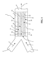
- a Y-type flow cell generally designated by reference numeral 1, has two inlets 2 and 3, respectively, and an outlet 4.
- the flow cell has a sensing surface 5 on a wall portion thereof.
- the sensing surface may, for example, be of the type described in U.S. Patents Nos. 5,242,828 and 5,436,161 and may, for instance, include a matrix coating in the form of carboxymethylated dextran.
- a laminar flow of a first fluid, indicated by arrow 6, is introduced through inlet 2, and a laminar flow of a second fluid, indicated by arrow 7, is introduced through inlet 3 such that the two fluids flow together over the sensing surface 5 with an interface (not shown) between them, exiting through outlet 4, as indicated by arrow 8.
- the position of the interface may be displaced laterally as desired and be set at any distance from either side wall of the flow cell. Immobilization of three different ligands to the sensing surface 5 is performed as described in steps (1) to (10) below.
- Fig. 2 which schematically illustrates the procedure.
- Each square in Fig. 2 represents a Y-cell, as shown in Fig. 1 , with the respective process step number indicated at the top thereof.
- the sensing surface 5 now exhibits three discrete sensing areas 14, 17 and 22, each supporting a different ligand, which sensing areas are separated mutually as well as to the flow cell walls 12, 19 by deactivated areas 11, 16, 21 and 23.
- the resulting Y-cell with the desired sensitized sensing surface is also shown in Fig. 2 , to the right of the step 10 Y-cell.
- the different sensing surface areas are immobilised from the edges of the surface towards the centre. This requires, however, that ligands have to be contacted with areas to which a ligand has already been immobilised. This may be avoided by a procedure in which the ligands are immobilised to the respective areas from the centre towards the edges. An embodiment of such a procedure is outlined below with reference to Fig. 3 .
- the flow cell 30 is a Y-cell similar to that shown in Figs. 1 and 2 , having two inlets 31, 32, an outlet 33 and a sensing surface on a wall portion thereof (not specifically indicated). Three detection spots, i.e. areas on the sensing surface that are measured by a detection system (not shown) are indicated at 34, 35 and 36. A number of images of flow cell 30, numbered from 1 to 9, are shown to illustrate the different steps of the procedure.
- the sensing surface may e.g. be carboxymethylated dextran
- the activating fluid may be an NHD/EDC-solution
- deactivating fluids may be sodium hydroxide solution and ethanolamine solution
- the blocking fluid buffer may be sodium hydroxide solution and ethanolamine solution.
- ligands may readily be coupled to more than three different areas by following the above described procedure.
- a third ligand may be coupled to the remaining part of the activated area by introducing the ligand through inlet 32.
- a fourth ligand without the ligand-containing fluid having to pass areas with immobilized ligands, i.e. by deactivating an outer part of the activated area (adjacent to the flow cell wall) prior to the introduction of the third ligand through inlet 32, reactivating the deactivated area after coupling of the third ligand, and subsequently introducing the fourth ligand through inlet 32 to couple the ligand to the reactivated area.
- a BIACORE ® S51 instrument (Biacore AB, Uppsala, Sweden) was used. This instrument has two Y-type flow cells which allow a dual flow of fluids over a sensor chip surface, so-called hydrodynamic addressing, as described in WO 99/36766 mentioned above.
- the instrument uses three parallel detection spots on the sensor chip, each detection spot occupying one diode row in a diode array detector for detecting light reflected at the detection spots on the sensor chip surface. The detection spots are mutually spaced by one diode row.
- Sensor Chip CM5 (Biacore AB, Uppsala, Sweden) which has a gold-coated surface with a covalently linked carboxymethyl-modified dextran polymer hydrogel.
- Running buffer was HBS-N (10 mM HEPES pH 7.4 and 150 mM NaCl) (Biacore AB, Uppsala, Sweden).
- the output from the instrument is a "sensorgram” which is a plot of detector response (measured in "resonance units", RU) as a function of time.
- An increase of 1000 RU corresponds to an increase of mass on the sensor surface of approximately 1 ng/mm 2 .
- Antibodies anti-IL-8, anti-IL-10 and anti-IL-12 against interleukin 8 (IL-8), interleukin 10 (IL-10) and interleukin 12 (IL-12) were diluted 10 times from stock solution with 10 mM acetate pH 4.5. They were then immobilized in the two flow cells of the instrument by the hydrodynamic addressing procedure described above with reference to Figs. 1 and 2 , using 10 minutes activation with EDC/NHS and sequential deactivation and ligand (antibody) immobilization. Each deactivation was performed with ethanolamine (100 mM, pH 8.5) for two minutes, and each antibody was injected for 7 minutes.
- each antibody was immobilized in parallel stripes extending through the spots used for detection in the BIACORE ® S51 instrument, meaning that with regard to the detector there was one diode row between each immobilized spot.
- each antibody was immobilized such that it extended into one third of the adjacent interspaces.
- the resulting immobilization levels in resonance units (RU) for the different ligands are shown in Tables 1 (flow cell 1) and 2 (flow cell 2) below. Bold values show targeted immobilization spots. Indicated in italics below each immobilization level value is the percentage immobilized, obtained by subtracting the baseline before injection of antibody from the baseline after subsequent deactivation with ethanolamine.
- the corresponding antigens IL-8, IL-10 and IL-12 were diluted to 500 ng/ml in HBS-N (Biacore AB, Uppsala, Sweden) and sequentially injected for 4 minutes in both flow cells. Between injections, the surfaces were regenerated with 0.1 trifluoroacetic acid (TFA) for 6 seconds.
- TFA trifluoroacetic acid
- the resulting binding levels (in RU) are shown in Tables 3 and 4 below. Below each binding value, calculated percent cross-talk is indicated in italics.
- Analyte antigen Diode row number (flow cell 1) 1 2 3 4 5 IL-8 1611 776 25 14 2 100.0 48.2 1.5 0.9 0.1 IL-10 2 287 484 6 -1 0.5 59.4 100.0 1.3 -0.3 IL-12 1 4 8 450 1076 0.1 0.4 0.8 41.8 100.0 Table 4 Analyte antigen Diode row number (flow cell 2) 1 2 3 4 5 IL-8 4 16 26 730 1451 0.3 1.1 1.8 50.3 100.0 IL-10 -3 8 328 272 1 - 0.9 2.5 100.0 83.1 0.3 IL-12 1183 396 7 2 -2 100.0 33.4 0.6 0.2 - 0.2
- cross-talk between spots was below 1%, except for IL-8 which bound by 1.5% and 1.8%, respectively, to the anti-IL-10 antibody, most likely due to cross-reactivity.
- Example 5 Following the procedure in Example 1 and using the same instrument and sensor chip, five different ligands were immobilized in a Y-cell. In this case, however, each ligand spot adjoined to the next one without any separating detector diode row. The interfaces between the spots were adjusted to obtain a 5% theoretical cross-talk to ensure homogeneity of the spots.
- the following ligands were sequentially immobilized: anti-IL-8, anti-myoglobin, anti-IL-10, anti-CKMB and anti-IL-12 (all from in-house sources, Biacore AB, Uppsala, Sweden).
- the resulting immobilization levels for flow cell 1, as well as the percentages cross-talk (in italics), are shown in Table 5 below.
- the antigens corresponding to the immobilized antibodies were then injected as described in Example 1, except that myoglobin and CKMB were each diluted to 5 ⁇ g/ml in HBS-N.
- the resulting binding level for each analyte in percent of that for the "active" spot (after subtraction of the average for buffer samples) are presented in Table 6 below.
- Table 6 Analyte antigen Diode row number (flow cell 2) 1 2 3 4 5 myoglobin 2.9 100.0 9.3 0.5 0.0 CKMB -2.4 -2.5 0.5 100.0 3.7 IL-8 100.0 3.9 1.8 1.0 -0.1 IL-10 -2.6 -2.2 100.0 -0.3 -2.8 IL-12 -0.4 -0.4 1.5 3.1 100.0
Description
- The present invention relates to a method of analysis comprising sensiting a sensing surface with multiple binding agents by passing a binding agent-containing fluid flow over the surface, and more particularly by using hydrodynamic addressing techniques to selectively direct fluid flows to desired surface areas.
- Flow cells are used extensively nowadays in a variety of analytical systems. Typically, the flow cell has an inlet opening, a flow channel with a sensing surface, and an outlet opening. A sample fluid to be investigated is introduced through the inlet opening, passes through the flow channel and leaves the flow cell through the outlet opening. The flow cell may have more than one inlet opening and optionally more than one outlet opening to permit desired manipulations of the flow pattern within the flow cell.
- The sensing surface usually comprises a substance layer to which a recognition element for an analyte in the sample is immobilised, typically a biochemical affinity partner to the analyte. When the analyte interacts with the recognition element, a physical or chemical change is produced on the sensing surface that can be detected by a detector, e.g. an optical, electrochemical or calorimetric detector. A flow channel may contain two or more sensing surfaces with different recognition elements.
- The sensing surface or surfaces in the flow cell may be functionalized, or sensitized, in situ, i.e. within the flow cell.
WO 90/05305 -
WO 99/36766 WO 99/36766 - For providing more than two differently sensitized sensing surface areas,
WO 99/36766 - A similar use of a ψ-type flow cell is disclosed in
WO 00/56444 - While the ψ-type flow cell is advantageous in comparison with the Y-type flow cell in that the former readily permits sensitization with more than two different ligands, the ψ-type flow cell requires the use of an additional pump (one pump for each fluid flow inlet) which considerably complicates the control of the different laminar flows. It would therefore be desired to be able to use a Y-type flow cell to sensitize a sensing surface with more than two different ligands.
- Accordingly, it is an object of the present invention to provide a method which permits coupling of multiple different ligands, or generally binding agents, to respective surface areas by hydrodynamic addressing using only two adjacent laminar fluid flows, such as e.g. in a Y-type flow cell.
- The above and other objects and advantages are obtained by a novel method of analysis comprising sensitising a sensing surface with multiple binding agents to respective areas of a substrate surface by hydrodynamic addressing, wherein each successive coupling of a binding agent to a substrate area is followed or preceded by selective deactivation or activation of a selected surface area or areas according to a particular coupling protocol, as defined in the independent claim.
- Further scope of applicability of the present invention will become apparent from dependent claims and the detailed description given hereinafter.
-
-
Fig. 1 is a schematic illustration of an embodiment of the method of the present invention using a Y-type flow cell. -
Fig. 2 is a schematic illustration of the different steps in the method relating toFig. 1 . -
Fig. 3 is a schematic illustration of another method embodiment of the present invention using a Y-type flow cell. - As mentioned above, the present invention is generally directed to the coupling of multiple binding agents to a substrate (solid support) surface using hydrodynamic addressing techniques to successively bring binding agent-containing fluid flows into selective contact with different surface areas to couple the different binding agents thereto. More particularly, two adjacent laminar fluid flows are provided which flow together over the substrate surface with an interface between them, as described in the aforementioned
WO 99/36766 - By adjusting the relative flow rates of the two fluid flows, the interface may be positioned laterally to make the different fluids contact respective desired areas of the substrate surface. To couple a binding agent to the substrate surface, one of the fluid flows contains a binding agent, and the other fluid flow is one that can not interact with the substrate surface, below frequently referred to as a blocking fluid. To permit coupling of the binding agent to the substrate surface, the surface should, of course, be sufficiently reactive towards the binding agent Preferably, the surface is activated by an activating agent as is per se well known in the art.
- According to the present invention, a binding agent may be coupled to a (preferably activated) surface followed by selective deactivation of the coupled surface area, and optionally of an adjacent area but less than the whole activated surface, and a different binding agent is then coupled to an adjacent activated surface area, followed by deactivation of the activated surface area. By proceeding in this manner with successive coupling of binding agents with deactivation after each coupling, multiple binding agents may readily be coupled to respective areas of an activated substrate surface, if desired with non-coupled areas between the coupled areas.
- Optionally, the procedure may start with deactivating an edge area of the activated substrate surface, and a binding agent is then coupled to an activated area adjacent to the deactivated edge area.
- While it is possible to carry out the coupling procedure of the invention from one side of the flow path to the other, it may be convenient to start from one side and successively couple a first number of binding agents, and then shift to the opposite side of the flow path and successively couple a second number of binding agents from that side. In this case, activation of the surface area to be coupled with this second number of agents may take place after coupling the first number of binding agents.
- Alternatively, a binding agent may be coupled to a (preferably activated) surface by selective deactivation of a part of the activated substrate surface, coupling of a binding agent to the remaining activated area, reactivation of at least a part of the deactivated area, and coupling of a different binding agent to the reactivated area. By proceeding in this way with successive activation and deactivation before each coupling of binding agent, multiple binding agents may be immobilized to respective areas of an activated surface.
- Optionally, a pre-activated surface may be used instead of activating the surface areas at the time of coupling the binding agents.
- It is not necessary that all the binding agents coupled to the substrate surface be different. However, usually at least two adjacent binding agent coupled areas should not support the same binding agent.
- Preferably, at least one surface area is not coupled with binding agent and used as a reference area(s).
- The term "binding agent" as used herein means any agent that is a member of a specific binding pair, including, for instance polypeptides, such as, e.g., proteins or fragments thereof, including antibodies; nucleic acids, e.g. oligonucleotides, polynucleotides, and the like; etc. The binding agent is often a ligand.
- The term "ligand" as used herein means a molecule that has a known or unknown affinity for a given analyte and can be immobilized on a predefined region of the surface. The ligand may be a naturally occurring molecule or one that has been synthesized. The ligand may be used per se or as aggregates with another species. Optionally, the ligand may also be a cell.
- The term "reactive" with respect to a substrate surface means that the surface should exhibit a binding moiety, such as e.g. a functional group, capable of coupling to a binding agent.
- The term "activation" means modification of a substrate surface to enable coupling a binding agent thereto, usually modification of a functional group on the substrate surface.
- The term "deactivation" means modification of a reactive substrate surface, usually of an activated functional group thereon, such that coupling of a binding agent to the surface is substantially prevented. Deactivation may include restoring an original functional group or making a reactive functional group or other reactive moiety inactive in other ways.
- Activating and deactivating agents that may be used for the purposes of the present invention are per se well known to a person skilled in the art and may readily be selected for each particular situation.
- The choice of activating agent (and method) depends, of course, on the functional group to be activated and on the desired reactive group to be obtained by the activation, which in turn depends on the binding agent to be coupled to the substrate surface. Exemplary functional group/activating agent combinations include those introducing hydroxysuccinimide esters, nitro- and dinitrophenyl esters, tosylates, mesylates, triflates and disulfides. For example, a hydroxy group may be reacted to activated ester with disuccinic carbonate, or to epoxide with a diepoxide. A carboxy group may be activated to N-hydroxysuccinimide ester by reaction with N-hydroxysuccinimide (NHS) and carbodiimide, e.g. 1-[3-dimethylamino)propyl]-3-ethylcarbodiimide (EDC), or to dinitrophenyl ester by reaction with dinitrophenol. A thiol (mercapto) group may be activated to a disulfide group by reaction with e.g. a dipyridyldisulfide or (2-pyridinyldithio)ethaneamine.
- For example, NHS/EDC activation of carboxy groups may be used to couple binding agents having an amine function (so-called amine coupling) or an aldehyde function (so-called aldehyde coupling).
- NHS/EDC activation may also be used to introduce thiol groups, e.g. by reaction with dithioerythritol (DTE). These thiol groups may then either (i) be reacted with an active disulfide group of a binding agent (so-called surface thiol coupling), or (ii) be activated to disulfide groups which may be reacted with a thiol function of a binding agent (so-called ligand thiol coupling).
- Also avidin or streptavidin may be coupled to an NHS/EDC-activated surface to permit capture of a biotinylated binding agent (so-called avidin coupling).
- The choice of deactivating agent depends, of course, on the active group(s) to be deactivated. For example, N-hydroxysuccinimide esters may be deactivated with ethanolamine or sodium hydroxide, deactivation with sodium hydroxide being reversible, i.e. the deactivated surface may be reactivated by activation with an activating agent.
- The term "coupling" as used herein is to be interpreted in a broad sense and includes covalent binding as well as other types of binding.
- The method of the invention is preferably performed in a flow cell. Suitable flow cells for use in the present invention may assume a number of forms, the design of which may vary widely. A preferred type of flow cell is the "Y-flow cell" which has two inlets and one outlet and which is described in, for example, the above-mentioned
WO 99/36766 - The substrate surface is usually a sensing surface, which term in the present context is to be construed broadly. The sensing surface may, for example, be a surface or surface layer that can interact specifically with a species present in a fluid, a surface or surface layer that can be chemically or physically sensitised to permit such interaction, or a surface or surface layer that can be chemically or physically activated to permit sensitisation thereof. A flow cell may contain one or more sensing surfaces.
- Binding events at the sensing surface may be detected by numerous techniques. In many cases it is favourable to use so-called non-label methods. Representative such detection methods include, but are not limited to, mass detection methods, such as piezoelectric, optical, thermo-optical and surface acoustic wave (SAW) device methods, and electrochemical methods, such as potentiometric, conductometric, amperometric and capacitance/impedance methods. With regard to optical detection methods, representative methods include those that detect mass surface concentration, such as reflection-optical methods, including both external and internal reflection methods, angle, wavelength, polarization, or phase resolved, for example evanescent wave ellipsometry and evanescent wave spectroscopy (EWS, or internal reflection spectroscopy), both may include evanescent field enhancement via surface plasmon resonance (SPR), Brewster angle refractometry, critical angle refractometry, frustrated total reflection (FTR), scattered total internal reflection (STIR), which may include scatter enhancing labels, optical wave guide sensors; external reflection imaging, evanescent wave-based imaging such as critical angle resolved imaging, Brewster angle resolved imaging, SPR-angle resolved imaging, and the like. Further, photometric and imaging/microscopy methods, "per se" or combined with reflection methods, based on for example surface enhanced Raman spectroscopy (SERS), surface enhanced resonance Raman spectroscopy (SERRS), evanescent wave fluorescence (TIRF) and phosphorescence may be mentioned, as well as waveguide interferometers, waveguide leaking mode spectroscopy, reflective interference spectroscopy (RIfS), transmission interferometry, holographic spectroscopy, and atomic force microscopy (AFR).
- SPR spectroscopy may be mentioned as an exemplary commercially available analytical system to which the present invention may be applied. One type of SPR-based biosensors is sold by Biacore AB (Uppsala, Sweden) under the trade name BIACORE®. These biosensors utilize a SPR based mass-sensing technique to provide a "real-time" binding interaction analysis between a surface bound ligand and an analyte of interest.
- The basic principles of the invention will now be further described with reference to
Fig. 1 . A Y-type flow cell, generally designated byreference numeral 1, has twoinlets outlet 4. The flow cell has asensing surface 5 on a wall portion thereof. The sensing surface may, for example, be of the type described inU.S. Patents Nos. 5,242,828 and5,436,161 and may, for instance, include a matrix coating in the form of carboxymethylated dextran. - A laminar flow of a first fluid, indicated by
arrow 6, is introduced throughinlet 2, and a laminar flow of a second fluid, indicated byarrow 7, is introduced throughinlet 3 such that the two fluids flow together over thesensing surface 5 with an interface (not shown) between them, exiting throughoutlet 4, as indicated byarrow 8. By adjusting the relative flow rates of the two fluid flows, the position of the interface may be displaced laterally as desired and be set at any distance from either side wall of the flow cell. Immobilization of three different ligands to thesensing surface 5 is performed as described in steps (1) to (10) below. Reference is simultaneously made toFig. 2 which schematically illustrates the procedure. Each square inFig. 2 represents a Y-cell, as shown inFig. 1 , with the respective process step number indicated at the top thereof. - (1) The procedure is started with the
first fluid 6 being a fluid containing an activating agent, and thesecond fluid 7 being a blocking fluid (i.e. one that does not affect or interact with the sensing surface), such as buffer. The interface between the two fluid flows is positioned such that the activating fluid selectively covers a sensing surface area which, in the illustrated case, extends over more than half the lateral extension of the sensing surface as indicated by arrow 9. If thesensing surface 5 includes a layer of carboxymethylated dextran as suggested above, the activating agent may be N-hydroxysuccinimide (NHS) together with N-ethyl-N'-(dimethylaminopropyl)-carbodiimide (EDC). It is, alternatively, possible to activate the whole sensing surface by replacing the two fluid flows by a single flow of activating fluid. - (2) The activating fluid is then replaced by a fluid containing a deactivating agent, and the interface between the two
fluid flows arrow 10, such that the deactivating fluid selectively covers anarea 11 close to theflow cell wall 12, the buffer fluid covering the rest of thesensing surface 5. Thearea 11 will thereby be deactivated so as not to react with ligand-containing fluid in the following step. If NHS/EDC is used as activating agent, the deactivating agent may, for example, be ethanolamine. - (3) The deactivating
fluid 6 is then replaced by a fluid containing a first ligand, e.g. a first monoclonal antibody, and the interface between the twofluid flows arrow 13, such that the ligand-containing fluid selectively covers the deactivatedarea 11 as well as an adjacent activatedarea 14. Thearea 14 will thereby have the first ligand coupled thereto. - (4) The ligand-containing
fluid 6 is then replaced by deactivating fluid, and the interface between the twofluid flows arrow 15, such that the deactivating fluid selectively coversareas area 16 which will thereby be deactivated. - (5) The deactivating
fluid 6 is then replaced by a fluid containing a second ligand, e.g. a second monoclonal antibody, and the interface between the twofluid flows areas area 17 extending between the points ofarrows 9 and 15. Thearea 17 will thereby have the second ligand coupled thereto. - (6) The ligand-containing
fluid 6 is then replaced by a deactivating fluid, and the interface between the twofluid flows areas - (7) The ligand-containing
fluid 6, introduced throughinlet 2, is then replaced by buffer, and thebuffer flow 7, introduced throughinlet 3, is replaced by activating fluid. The interface between the twofluid flows arrow 18, i.e. from theflow cell wall 19 towards but not up to the ligand-coupledarea 17. - (8) The activating
fluid 7 is then replaced by deactivating fluid, and the interface between the twofluid flows arrow 20 such that the deactivating fluid selectively covers an activatedarea 21 close to theflow cell wall 19 which area is thereby deactivated. - (9) The deactivating
fluid 7 is then replaced by a fluid containing a third ligand, e.g. a third monoclonal antibody, and the interface between the twofluid flows arrow 19, such that the ligand-containing fluid covers thearea 21 and an adjacent activatedarea 22 extending between the points ofarrows area 22 will thereby have the third ligand coupled thereto. - (10) Finally, the ligand-containing
fluid 7 is replaced by deactivating fluid, and the interface between the twofluid flows fluid 7 selectively covers the deactivatedarea 21, the ligand-coupledarea 22 and (in the illustrated case) anon-activated area 23 between the ligand-coupledareas areas 21 and 22). - The
sensing surface 5 now exhibits threediscrete sensing areas flow cell walls areas Fig. 2 , to the right of the step 10 Y-cell. - While in the above illustrated case three discrete areas have been immobilised with ligand, it is understood that by proceeding as described above with successive ligand-coupling and deactivation steps, from e.g. four, five or six to considerably more ligand-coupled areas may likewise readily be produced on a sensing surface, depending on among other things the flow cell, the size of the sensing surface, the precision and control of pumps, etc.
- In the above described immobilisation procedure, the different sensing surface areas are immobilised from the edges of the surface towards the centre. This requires, however, that ligands have to be contacted with areas to which a ligand has already been immobilised. This may be avoided by a procedure in which the ligands are immobilised to the respective areas from the centre towards the edges. An embodiment of such a procedure is outlined below with reference to
Fig. 3 . - In
Fig. 3 , theflow cell 30 is a Y-cell similar to that shown inFigs. 1 and2 , having twoinlets outlet 33 and a sensing surface on a wall portion thereof (not specifically indicated). Three detection spots, i.e. areas on the sensing surface that are measured by a detection system (not shown) are indicated at 34, 35 and 36. A number of images offlow cell 30, numbered from 1 to 9, are shown to illustrate the different steps of the procedure. The sensing surface may e.g. be carboxymethylated dextran, the activating fluid may be an NHD/EDC-solution, deactivating fluids may be sodium hydroxide solution and ethanolamine solution, and the blocking fluid buffer. - (1) The procedure is started by passing a laminar flow of activating fluid through
inlet 31 and blocking fluid throughinlet 32. In the illustrated case, the interface between the two fluid flows is positioned such that the activating fluid covers detection spots 34 and 35 (i.e. two thirds of the lateral extension of the sensing surface). - (2) The activating fluid is then replaced by deactivating fluid, and the interface is positioned such that the deactivating fluid covers detection spot 34 (i.e. the left third of the sensing surface) to deactivate that part of the activated surface area, leaving the centre area that includes
detection spot 35 activated. The deactivating fluid is selected such that the deactivated area may later be reactivated (e.g. sodium hydroxide as mentioned above). - (3) The deactivating fluid is then replaced by a fluid containing a first ligand, and the interface is positioned such that the ligand-containing fluid covers detection spots 34 and 35, i.e. the same area as that activated in step (1) above. Due to the deactivating step (2), the first ligand will only couple to the still activated centre area including
detection spot 35. - (4) The ligand-containing fluid is then replaced by activating fluid, and the interface is positioned such that the activating fluid covers the area that was deactivated in step (2) above (i.e. the left third of the sensing surface in
Fig. 3 ). - (5) The activating fluid is then replaced by a fluid containing a second ligand, and the interface is positioned such that ligand-containing fluid covers the area that was activated in step (4) above. Thereby, the second ligand will be coupled to this area. The sensing surface now has the second ligand coupled to the left area that includes
detection spot 34, and the first ligand to the centre area that includesdetection spot 35. - (6) The ligand-containing fluid supplied through
inlet 31 is then replaced by blocking fluid, and the blocking fluid supplied throughinlet 32 is replaced by activating fluid. The interface is now positioned such that the activating fluid covers the right third of the sensing surface to activate that area. - (7) The activating fluid is then replaced by a fluid containing a third ligand, and the interface is maintained in the same position as in step (6) above to thereby couple the third ligand to the area that was activated in step (4) and includes
detection spot 36. - (8) The activating fluid through
inlet 31 is then replaced by deactivating fluid andinlet 32 is closed to deactivate all three ligand-coupled areas of the sensing surface. In this case the deactivating fluid need not be one that permits reactivation as in step (2) and must not affect the immobilised ligands, e.g. ethanolamine. - (9) The sensing surface now has three different ligands coupled thereto, i.e. the second ligand coupled to a lateral area including
detection spot 34, the first ligand coupled a central area includingdetection spot 35, and the third ligand coupled to a lateral area includingdetection spot 36. - It is readily seen that ligands may readily be coupled to more than three different areas by following the above described procedure.
- An alternative immobilization procedure, which partly avoids contacting a ligand with an area or areas to which ligands have already been immobilized, and does not require reactivation of a deactivated surface, will be schematically described below with reference to
Fig. 3 again. - (1) Half the sensing surface is first activated by introducing activating fluid through
inlet 31 and blocking fluid throughinlet 32. - (2) A first ligand is then immobilized to an inner part (i.e. adjacent to the centre) of the activated area by introducing ligand through
inlet 32 and blocking fluid throughinlet 31, and positioning the fluid interface in the middle of the activated area. - (3) A second ligand is then immobilized to the remaining part of the activated area (i.e. adjacent to the flow cell wall) by introducing ligand through
inlet 31 and blocking fluid throughinlet 32. - (4) After deactivation of the areas coupled with the first and second ligands, respectively, third and fourth ligands may then be immobilized to the other half of the sensing surface by activating this area and successively coupling the ligands, introduced through
inlet 31, according to the method variant described above with reference toFigs. 1 and2 , i.e. with intermediate deactivation of the inner area coupled with the third ligand before introducing the fourth ligand. - Alternatively, a third ligand may be coupled to the remaining part of the activated area by introducing the ligand through
inlet 32. - By proceeding as described above with reference to
Fig. 3 , it is also possible to couple a fourth ligand without the ligand-containing fluid having to pass areas with immobilized ligands, i.e. by deactivating an outer part of the activated area (adjacent to the flow cell wall) prior to the introduction of the third ligand throughinlet 32, reactivating the deactivated area after coupling of the third ligand, and subsequently introducing the fourth ligand throughinlet 32 to couple the ligand to the reactivated area. - Numerous applications of a sensing surface to which multiple ligands have been immobilised at discrete areas as described above are readily apparent to a person skilled in the art and need not be detailed herein.
- The invention will now be illustrated further by the following examples.
- A BIACORE® S51 instrument (Biacore AB, Uppsala, Sweden) was used. This instrument has two Y-type flow cells which allow a dual flow of fluids over a sensor chip surface, so-called hydrodynamic addressing, as described in
WO 99/36766 - Antibodies anti-IL-8, anti-IL-10 and anti-IL-12 against interleukin 8 (IL-8), interleukin 10 (IL-10) and interleukin 12 (IL-12) (in-house sources, Biacore AB, Uppsala, Sweden), were diluted 10 times from stock solution with 10 mM acetate pH 4.5. They were then immobilized in the two flow cells of the instrument by the hydrodynamic addressing procedure described above with reference to
Figs. 1 and2 , using 10 minutes activation with EDC/NHS and sequential deactivation and ligand (antibody) immobilization. Each deactivation was performed with ethanolamine (100 mM, pH 8.5) for two minutes, and each antibody was injected for 7 minutes. - The different antibodies were immobilized in parallel stripes extending through the spots used for detection in the BIACORE® S51 instrument, meaning that with regard to the detector there was one diode row between each immobilized spot. However, in order to ensure that the immobilized antibodies within the detection spots were homogenous, each antibody was immobilized such that it extended into one third of the adjacent interspaces. The resulting immobilization levels in resonance units (RU) for the different ligands are shown in Tables 1 (flow cell 1) and 2 (flow cell 2) below. Bold values show targeted immobilization spots. Indicated in italics below each immobilization level value is the percentage immobilized, obtained by subtracting the baseline before injection of antibody from the baseline after subsequent deactivation with ethanolamine.
Table 1 Immobilized antibody Diode row number (flow cell 1) 1 2 3 4 5 anti-IL-8 31480 18821 280 189 116 100.0 46.0 -0.3 -0.5 -0.1 anti-IL-10 31917 28574 26629 18645 62 -14.4 32.2 100.0 47.7 -0.1 anti-IL-12 23892 14945 13037 9904 15611 -6.1 -20.3 -13.2 21.2 100.0 Table 2 Immobilized antibody Diode row number (flow cell 2) 1 2 3 4 5 anti-IL-8 123 152 147 20214 30138 -0.1 -0.3 -0.2 49.6 100.0 anti-IL-10 98 17142 26016 27174 30496 0.1 49.3 100.0 20.6 -13.0 anti-IL-12 16013 9407 13525 13877 23681 100.0 14.5 -8.7 -18.8 -12.0 - As shown in the tables, selective repeatable immobilization of ligands at the desired detection spots was obtained with no or very low "cross-talk" between spots.
- The corresponding antigens IL-8, IL-10 and IL-12 were diluted to 500 ng/ml in HBS-N (Biacore AB, Uppsala, Sweden) and sequentially injected for 4 minutes in both flow cells. Between injections, the surfaces were regenerated with 0.1 trifluoroacetic acid (TFA) for 6 seconds. The resulting binding levels (in RU) are shown in Tables 3 and 4 below. Below each binding value, calculated percent cross-talk is indicated in italics.
Table 3 Analyte antigen Diode row number (flow cell 1) 1 2 3 4 5 IL-8 1611 776 25 14 2 100.0 48.2 1.5 0.9 0.1 IL-10 2 287 484 6 -1 0.5 59.4 100.0 1.3 -0.3 IL-12 1 4 8 450 1076 0.1 0.4 0.8 41.8 100.0 Table 4 Analyte antigen Diode row number (flow cell 2) 1 2 3 4 5 IL-8 4 16 26 730 1451 0.3 1.1 1.8 50.3 100.0 IL-10 -3 8 328 272 1 -0.9 2.5 100.0 83.1 0.3 IL-12 1183 396 7 2 -2 100.0 33.4 0.6 0.2 -0.2 - As shown in the tables above, cross-talk between spots was below 1%, except for IL-8 which bound by 1.5% and 1.8%, respectively, to the anti-IL-10 antibody, most likely due to cross-reactivity.
- Following the procedure in Example 1 and using the same instrument and sensor chip, five different ligands were immobilized in a Y-cell. In this case, however, each ligand spot adjoined to the next one without any separating detector diode row. The interfaces between the spots were adjusted to obtain a 5% theoretical cross-talk to ensure homogeneity of the spots. The following ligands were sequentially immobilized: anti-IL-8, anti-myoglobin, anti-IL-10, anti-CKMB and anti-IL-12 (all from in-house sources, Biacore AB, Uppsala, Sweden). The resulting immobilization levels for
flow cell 1, as well as the percentages cross-talk (in italics), are shown in Table 5 below.Table 5 Immobilized antibody Diode row number (flow cell 2) 1 2 3 4 5 anti-IL-8 27550 910 253 180 127 3 1 1 0 anti-myoglobin 32199 29280 1149 182 138 3 0 0 anti-IL-10 29762 26385 24325 1024 4 123 0 anti-IL-12 22680 15940 12330 1763 24848 1 0 0 -2 anti-CKMB 22769 16003 12690 19940 26576 0 0 2 - As appears from the table above, all the antibody immobilizations were successful, the maximum cross-talk obtained being 4%.
- The antigens corresponding to the immobilized antibodies were then injected as described in Example 1, except that myoglobin and CKMB were each diluted to 5 µg/ml in HBS-N. The resulting binding level for each analyte in percent of that for the "active" spot (after subtraction of the average for buffer samples) are presented in Table 6 below.
Table 6 Analyte antigen Diode row number (flow cell 2) 1 2 3 4 5 myoglobin 2.9 100.0 9.3 0.5 0.0 CKMB -2.4 -2.5 0.5 100.0 3.7 IL-8 100.0 3.9 1.8 1.0 -0.1 IL-10 -2.6 -2.2 100.0 -0.3 -2.8 IL-12 -0.4 -0.4 1.5 3.1 100.0
Claims (17)
- A method of analysis, comprisingsensitising a sensing surface with at least two different binding agents to respective defined areas of a substrate surface by hydrodynamic addressing based on two laminar fluid flows that flow together in the same direction over the substrate surface with an interface to each other, and selectively contacting a defined area of the substrate surface with a desired fluid by positioning the interface laterally through adjustment of the relative flow rates of the two fluid flows,contacting the sensitised areas with at least one analyte, andstudying interaction between the analyte and the sensing surface, wherein the step of sensitising comprises at least one of hydrodynamic addressing procedures A and B, wherein:procedure A comprises immobilizing a first binding agent to a first area of the substrate surface by contacting the area with a fluid containing the first binding agent, deactivating the first area by subjecting the area to a deactivating fluid, and immobilizing a second binding agent to a second area of the substrate surface by contacting a substrate surface area including the first and second areas with the second binding agent; andprocedure B comprises deactivating a first area of the substrate surface by subjecting the area to a deactivating fluid, immobilizing a first binding agent to a second area of the substrate surface by contacting the first and second areas with a fluid containing the first binding agent, activating at least a part of the first area by subjecting the area to an activating fluid, and immobilizing a second binding agent to the first area by contacting the first area with a fluid containing the second binding agent.
- The method according to claim 1, wherein procedure A comprises the steps of:a) providing a substrate surface, at least part of which is reactive to permit coupling of binding agents thereto;b) passing over the substrate surface a laminar flow of a fluid containing a first binding agent, and adjacent thereto a laminar flow of a blocking fluid that does not interact with the substrate surface, such that the two fluids flow together in the same direction with an interface to each other, and adjusting the relative flow rates of the two laminar fluid flows to position the interface such that the first binding agent-containing fluid selectively contacts a first reactive area of the substrate surface to couple the first binding agent thereto;c) replacing the flow of the first binding agent-containing fluid with a laminar flow of a deactivating fluid, and positioning the interface laterally such that the deactivating fluid selectively contacts at least the first binding agent-coupled area but less than the whole reactive surface area for deactivation thereof;d) replacing the flow of the deactivating fluid with a laminar flow of a fluid containing the second binding agent, and positioning the interface laterally such that the second binding agent-containing fluid selectively contacts the deactivated area and an adjacent second reactive area of the substrate surface to selectively couple the second binding agent to the second area; and, optionally,e) replacing the flow of the second binding agent-containing fluid with a laminar flow of deactivating fluid, and positioning the interface laterally such that the deactivating fluid selectively contacts at least the deactivated area and the second binding agent-coupled area of the substrate surface for deactivation thereof.
- The method according to claim 1, wherein procedure B comprises the steps of:a) providing a substrate surface, at least part of which is reactive to permit coupling of binding agents thereto;b) passing over the substrate surface a laminar flow of a deactivating fluid, and adjacent thereto a laminar flow of a blocking fluid that does not interact with the substrate surface, such that the two fluids flow together in the same direction with an interface to each other, and adjusting the relative flow rates of the two laminar fluid flows to position the interface such that the deactivating fluid selectively contacts a first reactive area of the substrate surface for deactivation thereof;c) replacing the flow of the deactivating fluid with a laminar flow of a fluid containing a first binding agent, and positioning the interface laterally such that the first binding agent-containing fluid selectively contacts the deactivated area and an adjacent second reactive area of the substrate surface to selectively couple the first binding agent to the second area;d) replacing the flow of the first binding agent-containing fluid with a laminar flow of activating fluid, and positioning the interface laterally such that the activating fluid selectively contacts at least a part of the deactivated first area for activation thereof; ande) replacing the flow of the activating fluid with a laminar flow of a fluid containing a second binding agent, and positioning the interface laterally such that the second binding agent-containing fluid selectively contacts the activated first area to selectively couple the second binding agent thereto.
- The method according to claim 2 or 3, wherein steps b) to e) are repeated one or more times to couple at least one additional binding agent to a respective reactive area on the substrate surface.
- The method according to any one of claims 1 to 4, wherein at least one of the reactive areas of the substrate surface comprises activated functional groups.
- The method according to any one of claims 2 to 5, wherein step a) of claim 2 or claim 3 comprises passing a laminar flow of activating fluid over at least a part of the substrate surface to provide the at least partly reactive surface.
- The method according to any one of claims 2 to 5, wherein step a) of claim 2 or claim 3 comprises providing a surface with pre-activated functional groups.
- The method according to any one of claims 1 to 4, wherein at least one of the reactive areas of the substrate surface comprises functional groups capable of reacting with the binding agents without activation of the functional groups.
- The method according to any one of claims 2, or 4 to 8, which comprises the step of, prior to performing step b) of claim 2, passing over the substrate surface a laminar flow of deactivating fluid and an adjacent laminar flow of blocking fluid, and positioning the interface such that the deactivating fluid selectively contacts a reactive edge area of the substrate surface adjacent to the first area to be contacted with binding agent in step b) for deactivation thereof.
- The method according to any one of claims 2, or 4 to 9, which comprises performing steps b) to e) of claim 2 in the opposite lateral direction to the flow path to couple at least one additional binding agent to a respective reactive area of the substrate surface.
- The method according to claim 10, which comprises activating an additional part of the substrate surface prior to performing steps b) to e) of claim 2 in the opposite lateral direction to the flow path.
- The method according to any one of claims 2, or 4 to 11, wherein in steps c) and e) of claim 2 the laminar flow of deactivating fluid is adjusted to contact also a reactive area adjacent to the binding agent-coupled area to provide a non-coupled area between neighbouring binding agent-coupled areas.
- The method according to any one of claims 1 to 8, wherein procedure B of claim 1 comprises immobilizing an additional binding agent to a third area situated on the other side of the second area immobilized with the first binding agent by selectively contacting the third area with a fluid containing the additional binding agent.
- The method according to claim 13, wherein the third area is activated prior to immobilizing the additional binding agent.
- The method according to any one of claims 1 to 14, wherein the substrate surface is a sensing surface of a sensor.
- The method according to claim 15, wherein the sensing surface is provided in a flow cell.
- The method according to claim 16, wherein the flow cell comprises two inlets and one outlet.
Applications Claiming Priority (5)
| Application Number | Priority Date | Filing Date | Title |
|---|---|---|---|
| US38462602P | 2002-05-31 | 2002-05-31 | |
| SE0201637A SE0201637D0 (en) | 2002-05-31 | 2002-05-31 | Method of coupling binding agents to a substrate surface |
| US384626P | 2002-05-31 | ||
| SE0201673 | 2002-06-03 | ||
| PCT/SE2003/000879 WO2003102580A1 (en) | 2002-05-31 | 2003-05-28 | Method of coupling binding agents to a substrate surface |
Publications (2)
| Publication Number | Publication Date |
|---|---|
| EP1509770A1 EP1509770A1 (en) | 2005-03-02 |
| EP1509770B1 true EP1509770B1 (en) | 2014-07-09 |
Family
ID=29714428
Family Applications (1)
| Application Number | Title | Priority Date | Filing Date |
|---|---|---|---|
| EP03738801.4A Expired - Lifetime EP1509770B1 (en) | 2002-05-31 | 2003-05-28 | Method of coupling binding agents to a substrate surface |
Country Status (4)
| Country | Link |
|---|---|
| US (2) | US20040058456A1 (en) |
| EP (1) | EP1509770B1 (en) |
| JP (1) | JP4468803B2 (en) |
| WO (1) | WO2003102580A1 (en) |
Cited By (6)
| Publication number | Priority date | Publication date | Assignee | Title |
|---|---|---|---|---|
| RU2728430C2 (en) * | 2015-09-18 | 2020-07-29 | Чугаи Сейяку Кабусики Кайся | Il-8-binding antibodies and use thereof |
| US11046784B2 (en) | 2006-03-31 | 2021-06-29 | Chugai Seiyaku Kabushiki Kaisha | Methods for controlling blood pharmacokinetics of antibodies |
| US11236168B2 (en) | 2012-08-24 | 2022-02-01 | Chugai Seiyaku Kabushiki Kaisha | Mouse FcγammaRII-specific Fc antibody |
| US11248053B2 (en) | 2007-09-26 | 2022-02-15 | Chugai Seiyaku Kabushiki Kaisha | Method of modifying isoelectric point of antibody via amino acid substitution in CDR |
| US11267868B2 (en) | 2013-04-02 | 2022-03-08 | Chugai Seiyaku Kabushiki Kaisha | Fc region variant |
| US11891434B2 (en) | 2010-11-30 | 2024-02-06 | Chugai Seiyaku Kabushiki Kaisha | Antigen-binding molecule capable of binding to plurality of antigen molecules repeatedly |
Families Citing this family (29)
| Publication number | Priority date | Publication date | Assignee | Title |
|---|---|---|---|---|
| US7193711B2 (en) | 2000-07-11 | 2007-03-20 | Maven Technologies, Llc | Imaging method and apparatus |
| US6594011B1 (en) | 2000-07-11 | 2003-07-15 | Maven Technologies, Llc | Imaging apparatus and method |
| US6833920B2 (en) | 2000-07-11 | 2004-12-21 | Maven Technologies Llc | Apparatus and method for imaging |
| US7023547B2 (en) | 2000-07-11 | 2006-04-04 | Maven Technologies, Llc | Apparatus including a biochip for imaging of biological samples and method |
| US7518724B2 (en) | 2000-07-11 | 2009-04-14 | Maven Technologies | Image acquisition, processing, and display |
| US20060141527A1 (en) * | 2004-12-29 | 2006-06-29 | Caracci Stephen J | Method for creating a reference region and a sample region on a biosensor and the resulting biosensor |
| US7300631B2 (en) * | 2005-05-02 | 2007-11-27 | Bioscale, Inc. | Method and apparatus for detection of analyte using a flexural plate wave device and magnetic particles |
| US7611908B2 (en) * | 2005-05-02 | 2009-11-03 | Bioscale, Inc. | Method and apparatus for therapeutic drug monitoring using an acoustic device |
| US7749445B2 (en) * | 2005-05-02 | 2010-07-06 | Bioscale, Inc. | Method and apparatus for analyzing bioprocess fluids |
| US7648844B2 (en) * | 2005-05-02 | 2010-01-19 | Bioscale, Inc. | Method and apparatus for detection of analyte using an acoustic device |
| US7867783B2 (en) | 2007-02-22 | 2011-01-11 | Maven Technologies, Llc | Apparatus and method for performing ligand binding assays on microarrays in multiwell plates |
| US7863037B1 (en) | 2007-04-04 | 2011-01-04 | Maven Technologies, Llc | Ligand binding assays on microarrays in closed multiwell plates |
| US7799558B1 (en) | 2007-05-22 | 2010-09-21 | Dultz Shane C | Ligand binding assays on microarrays in closed multiwell plates |
| EP2179261B1 (en) | 2007-07-23 | 2021-09-15 | Sartorius BioAnalytical Instruments, Inc | Fluidic configuration for flow injection analysis system |
| WO2009033056A1 (en) * | 2007-09-06 | 2009-03-12 | Bioscale, Inc. | Reusable detection surfaces and methods of using same |
| CA2721052C (en) | 2008-04-11 | 2023-02-21 | Chugai Seiyaku Kabushiki Kaisha | Antigen-binding molecule capable of binding to two or more antigen molecules repeatedly |
| US8039270B2 (en) | 2008-05-22 | 2011-10-18 | Maven Technologies, Llc | Apparatus and method for performing ligand binding assays on microarrays in multiwell plates |
| US7981664B1 (en) | 2008-05-22 | 2011-07-19 | Maven Technologies, Llc | Apparatus and method for performing ligand binding assays on microarrays in multiwell plates |
| EP2287610A1 (en) * | 2009-08-20 | 2011-02-23 | Corning Incorporated | Thiol-modified surface immobilization article and method |
| US8355133B2 (en) | 2009-12-30 | 2013-01-15 | Maven Technologies, Llc | Biological testing with sawtooth-shaped prisms |
| WO2012102663A1 (en) * | 2011-01-24 | 2012-08-02 | Ge Healthcare Bio-Sciences Ab | Method of coupling binding agents to a substrate surface |
| JP6501521B2 (en) | 2012-08-24 | 2019-04-17 | 中外製薬株式会社 | FcγRIIb-specific Fc region variant |
| WO2014183096A1 (en) * | 2013-05-09 | 2014-11-13 | Quanterix Corporation | Methods, materials, and kits for covalently associating molecular species with a surface of an object |
| TWI779010B (en) | 2014-12-19 | 2022-10-01 | 日商中外製藥股份有限公司 | ANTI-MYOSTATIN ANTIBODIES, POLYPEPTIDES CONTAINING VARIANT Fc REGIONs, AND METHODS OF USE |
| US9969800B2 (en) | 2015-02-05 | 2018-05-15 | Chugai Seiyaku Kabushiki Kaisha | IL-8 antibodies |
| US11359009B2 (en) | 2015-12-25 | 2022-06-14 | Chugai Seiyaku Kabushiki Kaisha | Anti-myostatin antibodies and methods of use |
| SG11201801024XA (en) | 2016-08-05 | 2018-05-30 | Chugai Pharmaceutical Co Ltd | Therapeutic or preventive compositions for il-8-related diseases |
| SG10201607778XA (en) | 2016-09-16 | 2018-04-27 | Chugai Pharmaceutical Co Ltd | Anti-Dengue Virus Antibodies, Polypeptides Containing Variant Fc Regions, And Methods Of Use |
| CN116327926A (en) | 2018-03-15 | 2023-06-27 | 中外制药株式会社 | Anti-dengue virus antibodies with cross-reactivity to Zika virus and methods of use |
Family Cites Families (7)
| Publication number | Priority date | Publication date | Assignee | Title |
|---|---|---|---|---|
| SE462408B (en) * | 1988-11-10 | 1990-06-18 | Pharmacia Ab | OPTICAL BIOSENSOR SYSTEM USING SURFACE MONITORING RESONSE FOR THE DETECTION OF A SPECIFIC BIOMOLIC CYCLE, TO CALIBRATE THE SENSOR DEVICE AND TO CORRECT FOUND BASELINE OPERATION IN THE SYSTEM |
| SE8804074D0 (en) | 1988-11-10 | 1988-11-10 | Pharmacia Ab | SENSOR UNIT AND ITS USE IN BIOSENSOR SYSTEM |
| SE462454B (en) | 1988-11-10 | 1990-06-25 | Pharmacia Ab | METHOD FOR USE IN BIOSENSORS |
| AU6354796A (en) | 1995-06-23 | 1997-01-22 | Novartis Ag | Flow cell |
| US6200814B1 (en) | 1998-01-20 | 2001-03-13 | Biacore Ab | Method and device for laminar flow on a sensing surface |
| WO2000056444A2 (en) | 1999-03-24 | 2000-09-28 | Torsana Biosensor A/S | Spatially directed interaction on a solid surface |
| SE0102331D0 (en) * | 2001-06-29 | 2001-06-29 | Biacore Ab | Flow cell method |
-
2003
- 2003-05-28 EP EP03738801.4A patent/EP1509770B1/en not_active Expired - Lifetime
- 2003-05-28 WO PCT/SE2003/000879 patent/WO2003102580A1/en active Application Filing
- 2003-05-28 JP JP2004509415A patent/JP4468803B2/en not_active Expired - Lifetime
- 2003-05-30 US US10/449,823 patent/US20040058456A1/en not_active Abandoned
-
2009
- 2009-10-08 US US12/575,621 patent/US9174214B2/en not_active Expired - Lifetime
Cited By (6)
| Publication number | Priority date | Publication date | Assignee | Title |
|---|---|---|---|---|
| US11046784B2 (en) | 2006-03-31 | 2021-06-29 | Chugai Seiyaku Kabushiki Kaisha | Methods for controlling blood pharmacokinetics of antibodies |
| US11248053B2 (en) | 2007-09-26 | 2022-02-15 | Chugai Seiyaku Kabushiki Kaisha | Method of modifying isoelectric point of antibody via amino acid substitution in CDR |
| US11891434B2 (en) | 2010-11-30 | 2024-02-06 | Chugai Seiyaku Kabushiki Kaisha | Antigen-binding molecule capable of binding to plurality of antigen molecules repeatedly |
| US11236168B2 (en) | 2012-08-24 | 2022-02-01 | Chugai Seiyaku Kabushiki Kaisha | Mouse FcγammaRII-specific Fc antibody |
| US11267868B2 (en) | 2013-04-02 | 2022-03-08 | Chugai Seiyaku Kabushiki Kaisha | Fc region variant |
| RU2728430C2 (en) * | 2015-09-18 | 2020-07-29 | Чугаи Сейяку Кабусики Кайся | Il-8-binding antibodies and use thereof |
Also Published As
| Publication number | Publication date |
|---|---|
| JP4468803B2 (en) | 2010-05-26 |
| WO2003102580A1 (en) | 2003-12-11 |
| EP1509770A1 (en) | 2005-03-02 |
| US20100029015A1 (en) | 2010-02-04 |
| US20040058456A1 (en) | 2004-03-25 |
| AU2003245189B2 (en) | 2008-10-23 |
| JP2005528611A (en) | 2005-09-22 |
| US9174214B2 (en) | 2015-11-03 |
| AU2003245189A1 (en) | 2003-12-19 |
| WO2003102580A8 (en) | 2005-01-13 |
Similar Documents
| Publication | Publication Date | Title |
|---|---|---|
| EP1509770B1 (en) | Method of coupling binding agents to a substrate surface | |
| EP1682261B1 (en) | Method for carrying out multiple binding reactions in an array format | |
| US7015043B2 (en) | Flow cell method | |
| Homola et al. | Multi-analyte surface plasmon resonance biosensing | |
| US7396676B2 (en) | Evanescent wave sensor with attached ligand | |
| Baird et al. | Current and emerging commercial optical biosensors | |
| US5492840A (en) | Surface plasmon resonance sensor unit and its use in biosensor systems | |
| Malmqvist et al. | Biomolecular interaction analysis: affinity biosensor technologies for functional analysis of proteins | |
| EP1021703B1 (en) | Method and device for laminar flow on a sensing surface | |
| US20040091862A1 (en) | Method and device for detecting temperature-dependent parameters, such as the association/dissociation parameters and/or the equilibrium constant of complexes comprising at least two components | |
| US20130295587A1 (en) | Method of coupling binding agents to a substrate surface | |
| EP1456659B1 (en) | Immobilization of binding agents | |
| EP1780546A1 (en) | Evanescent wave sensor | |
| EP1724584A1 (en) | Evanescent wave sensor with attached ligand | |
| EP2397224A1 (en) | Apparatus and platform for multiplex analysis | |
| Vetter | Chemical microarrays, fragment diversity, label‐free imaging by plasmon resonance—a chemical genomics approach | |
| AU2002345465B2 (en) | Flow cell method | |
| AU2003245189B8 (en) | Method of coupling binding agents to a substrate surface | |
| AU2002345465A1 (en) | Flow cell method | |
| LIGLER et al. | Planar waveguides for fluorescence biosensors |
Legal Events
| Date | Code | Title | Description |
|---|---|---|---|
| PUAI | Public reference made under article 153(3) epc to a published international application that has entered the european phase |
Free format text: ORIGINAL CODE: 0009012 |
|
| 17P | Request for examination filed |
Effective date: 20041123 |
|
| AK | Designated contracting states |
Kind code of ref document: A1 Designated state(s): AT BE BG CH CY CZ DE DK EE ES FI FR GB GR HU IE IT LI LU MC NL PT RO SE SI SK TR |
|
| RTI1 | Title (correction) |
Free format text: METHOD OF COUPLING BINDING AGENTS TO A SUBSTRATE SURFACE |
|
| RAP1 | Party data changed (applicant data changed or rights of an application transferred) |
Owner name: GE HEALTHCARE BIO-SCIENCES AB |
|
| 17Q | First examination report despatched |
Effective date: 20100531 |
|
| GRAP | Despatch of communication of intention to grant a patent |
Free format text: ORIGINAL CODE: EPIDOSNIGR1 |
|
| INTG | Intention to grant announced |
Effective date: 20140224 |
|
| GRAS | Grant fee paid |
Free format text: ORIGINAL CODE: EPIDOSNIGR3 |
|
| GRAA | (expected) grant |
Free format text: ORIGINAL CODE: 0009210 |
|
| AK | Designated contracting states |
Kind code of ref document: B1 Designated state(s): AT BE BG CH CY CZ DE DK EE ES FI FR GB GR HU IE IT LI LU MC NL PT RO SE SI SK TR |
|
| REG | Reference to a national code |
Ref country code: GB Ref legal event code: FG4D |
|
| REG | Reference to a national code |
Ref country code: CH Ref legal event code: EP Ref country code: AT Ref legal event code: REF Ref document number: 676750 Country of ref document: AT Kind code of ref document: T Effective date: 20140715 |
|
| REG | Reference to a national code |
Ref country code: IE Ref legal event code: FG4D |
|
| REG | Reference to a national code |
Ref country code: DE Ref legal event code: R096 Ref document number: 60346451 Country of ref document: DE Effective date: 20140821 |
|
| REG | Reference to a national code |
Ref country code: AT Ref legal event code: MK05 Ref document number: 676750 Country of ref document: AT Kind code of ref document: T Effective date: 20140709 |
|
| REG | Reference to a national code |
Ref country code: NL Ref legal event code: VDEP Effective date: 20140709 |
|
| PG25 | Lapsed in a contracting state [announced via postgrant information from national office to epo] |
Ref country code: PT Free format text: LAPSE BECAUSE OF FAILURE TO SUBMIT A TRANSLATION OF THE DESCRIPTION OR TO PAY THE FEE WITHIN THE PRESCRIBED TIME-LIMIT Effective date: 20141110 Ref country code: BG Free format text: LAPSE BECAUSE OF FAILURE TO SUBMIT A TRANSLATION OF THE DESCRIPTION OR TO PAY THE FEE WITHIN THE PRESCRIBED TIME-LIMIT Effective date: 20141009 Ref country code: SE Free format text: LAPSE BECAUSE OF FAILURE TO SUBMIT A TRANSLATION OF THE DESCRIPTION OR TO PAY THE FEE WITHIN THE PRESCRIBED TIME-LIMIT Effective date: 20140709 Ref country code: ES Free format text: LAPSE BECAUSE OF FAILURE TO SUBMIT A TRANSLATION OF THE DESCRIPTION OR TO PAY THE FEE WITHIN THE PRESCRIBED TIME-LIMIT Effective date: 20140709 Ref country code: FI Free format text: LAPSE BECAUSE OF FAILURE TO SUBMIT A TRANSLATION OF THE DESCRIPTION OR TO PAY THE FEE WITHIN THE PRESCRIBED TIME-LIMIT Effective date: 20140709 Ref country code: GR Free format text: LAPSE BECAUSE OF FAILURE TO SUBMIT A TRANSLATION OF THE DESCRIPTION OR TO PAY THE FEE WITHIN THE PRESCRIBED TIME-LIMIT Effective date: 20141010 |
|
| PG25 | Lapsed in a contracting state [announced via postgrant information from national office to epo] |
Ref country code: AT Free format text: LAPSE BECAUSE OF FAILURE TO SUBMIT A TRANSLATION OF THE DESCRIPTION OR TO PAY THE FEE WITHIN THE PRESCRIBED TIME-LIMIT Effective date: 20140709 Ref country code: CY Free format text: LAPSE BECAUSE OF FAILURE TO SUBMIT A TRANSLATION OF THE DESCRIPTION OR TO PAY THE FEE WITHIN THE PRESCRIBED TIME-LIMIT Effective date: 20140709 Ref country code: NL Free format text: LAPSE BECAUSE OF FAILURE TO SUBMIT A TRANSLATION OF THE DESCRIPTION OR TO PAY THE FEE WITHIN THE PRESCRIBED TIME-LIMIT Effective date: 20140709 |
|
| REG | Reference to a national code |
Ref country code: DE Ref legal event code: R097 Ref document number: 60346451 Country of ref document: DE |
|
| PG25 | Lapsed in a contracting state [announced via postgrant information from national office to epo] |
Ref country code: IT Free format text: LAPSE BECAUSE OF FAILURE TO SUBMIT A TRANSLATION OF THE DESCRIPTION OR TO PAY THE FEE WITHIN THE PRESCRIBED TIME-LIMIT Effective date: 20140709 Ref country code: CZ Free format text: LAPSE BECAUSE OF FAILURE TO SUBMIT A TRANSLATION OF THE DESCRIPTION OR TO PAY THE FEE WITHIN THE PRESCRIBED TIME-LIMIT Effective date: 20140709 Ref country code: EE Free format text: LAPSE BECAUSE OF FAILURE TO SUBMIT A TRANSLATION OF THE DESCRIPTION OR TO PAY THE FEE WITHIN THE PRESCRIBED TIME-LIMIT Effective date: 20140709 Ref country code: SK Free format text: LAPSE BECAUSE OF FAILURE TO SUBMIT A TRANSLATION OF THE DESCRIPTION OR TO PAY THE FEE WITHIN THE PRESCRIBED TIME-LIMIT Effective date: 20140709 Ref country code: RO Free format text: LAPSE BECAUSE OF FAILURE TO SUBMIT A TRANSLATION OF THE DESCRIPTION OR TO PAY THE FEE WITHIN THE PRESCRIBED TIME-LIMIT Effective date: 20140709 Ref country code: DK Free format text: LAPSE BECAUSE OF FAILURE TO SUBMIT A TRANSLATION OF THE DESCRIPTION OR TO PAY THE FEE WITHIN THE PRESCRIBED TIME-LIMIT Effective date: 20140709 |
|
| PLBE | No opposition filed within time limit |
Free format text: ORIGINAL CODE: 0009261 |
|
| STAA | Information on the status of an ep patent application or granted ep patent |
Free format text: STATUS: NO OPPOSITION FILED WITHIN TIME LIMIT |
|
| 26N | No opposition filed |
Effective date: 20150410 |
|
| PG25 | Lapsed in a contracting state [announced via postgrant information from national office to epo] |
Ref country code: SI Free format text: LAPSE BECAUSE OF FAILURE TO SUBMIT A TRANSLATION OF THE DESCRIPTION OR TO PAY THE FEE WITHIN THE PRESCRIBED TIME-LIMIT Effective date: 20140709 |
|
| REG | Reference to a national code |
Ref country code: CH Ref legal event code: PL |
|
| PG25 | Lapsed in a contracting state [announced via postgrant information from national office to epo] |
Ref country code: CH Free format text: LAPSE BECAUSE OF NON-PAYMENT OF DUE FEES Effective date: 20150531 Ref country code: LU Free format text: LAPSE BECAUSE OF FAILURE TO SUBMIT A TRANSLATION OF THE DESCRIPTION OR TO PAY THE FEE WITHIN THE PRESCRIBED TIME-LIMIT Effective date: 20150528 Ref country code: LI Free format text: LAPSE BECAUSE OF NON-PAYMENT OF DUE FEES Effective date: 20150531 Ref country code: MC Free format text: LAPSE BECAUSE OF FAILURE TO SUBMIT A TRANSLATION OF THE DESCRIPTION OR TO PAY THE FEE WITHIN THE PRESCRIBED TIME-LIMIT Effective date: 20140709 |
|
| REG | Reference to a national code |
Ref country code: IE Ref legal event code: MM4A |
|
| REG | Reference to a national code |
Ref country code: FR Ref legal event code: ST Effective date: 20160129 |
|
| PG25 | Lapsed in a contracting state [announced via postgrant information from national office to epo] |
Ref country code: IE Free format text: LAPSE BECAUSE OF NON-PAYMENT OF DUE FEES Effective date: 20150528 |
|
| PG25 | Lapsed in a contracting state [announced via postgrant information from national office to epo] |
Ref country code: FR Free format text: LAPSE BECAUSE OF NON-PAYMENT OF DUE FEES Effective date: 20150601 |
|
| PG25 | Lapsed in a contracting state [announced via postgrant information from national office to epo] |
Ref country code: BE Free format text: LAPSE BECAUSE OF FAILURE TO SUBMIT A TRANSLATION OF THE DESCRIPTION OR TO PAY THE FEE WITHIN THE PRESCRIBED TIME-LIMIT Effective date: 20140709 |
|
| PG25 | Lapsed in a contracting state [announced via postgrant information from national office to epo] |
Ref country code: HU Free format text: LAPSE BECAUSE OF FAILURE TO SUBMIT A TRANSLATION OF THE DESCRIPTION OR TO PAY THE FEE WITHIN THE PRESCRIBED TIME-LIMIT; INVALID AB INITIO Effective date: 20030528 |
|
| PG25 | Lapsed in a contracting state [announced via postgrant information from national office to epo] |
Ref country code: TR Free format text: LAPSE BECAUSE OF FAILURE TO SUBMIT A TRANSLATION OF THE DESCRIPTION OR TO PAY THE FEE WITHIN THE PRESCRIBED TIME-LIMIT Effective date: 20140709 |
|
| REG | Reference to a national code |
Ref country code: DE Ref legal event code: R081 Ref document number: 60346451 Country of ref document: DE Owner name: CYTIVA SWEDEN AB, SE Free format text: FORMER OWNER: GE HEALTHCARE BIO-SCIENCES AB, UPPSALA, SE |
|
| PGFP | Annual fee paid to national office [announced via postgrant information from national office to epo] |
Ref country code: GB Payment date: 20220407 Year of fee payment: 20 Ref country code: DE Payment date: 20220406 Year of fee payment: 20 |
|
| REG | Reference to a national code |
Ref country code: DE Ref legal event code: R071 Ref document number: 60346451 Country of ref document: DE |
|
| REG | Reference to a national code |
Ref country code: GB Ref legal event code: PE20 Expiry date: 20230527 |
|
| PG25 | Lapsed in a contracting state [announced via postgrant information from national office to epo] |
Ref country code: GB Free format text: LAPSE BECAUSE OF EXPIRATION OF PROTECTION Effective date: 20230527 |